EP0455355B1 - Engine mounting assembly - Google Patents
Engine mounting assembly Download PDFInfo
- Publication number
- EP0455355B1 EP0455355B1 EP91303058A EP91303058A EP0455355B1 EP 0455355 B1 EP0455355 B1 EP 0455355B1 EP 91303058 A EP91303058 A EP 91303058A EP 91303058 A EP91303058 A EP 91303058A EP 0455355 B1 EP0455355 B1 EP 0455355B1
- Authority
- EP
- European Patent Office
- Prior art keywords
- arms
- structures
- mounting assembly
- location
- engine
- Prior art date
- Legal status (The legal status is an assumption and is not a legal conclusion. Google has not performed a legal analysis and makes no representation as to the accuracy of the status listed.)
- Expired - Lifetime
Links
- 230000033001 locomotion Effects 0.000 claims description 28
- 238000002955 isolation Methods 0.000 claims description 14
- 230000006835 compression Effects 0.000 claims description 13
- 238000007906 compression Methods 0.000 claims description 13
- 230000005540 biological transmission Effects 0.000 claims description 7
- 230000000452 restraining effect Effects 0.000 claims 2
- 229920001971 elastomer Polymers 0.000 description 8
- 239000000806 elastomer Substances 0.000 description 8
- 230000000712 assembly Effects 0.000 description 7
- 238000000429 assembly Methods 0.000 description 7
- 239000012530 fluid Substances 0.000 description 5
- 239000002184 metal Substances 0.000 description 5
- 230000008901 benefit Effects 0.000 description 4
- 239000000463 material Substances 0.000 description 4
- 230000003068 static effect Effects 0.000 description 3
- 238000010276 construction Methods 0.000 description 2
- 239000013536 elastomeric material Substances 0.000 description 2
- 238000009434 installation Methods 0.000 description 2
- 230000009257 reactivity Effects 0.000 description 2
- 238000010008 shearing Methods 0.000 description 2
- 125000006850 spacer group Chemical group 0.000 description 2
- 230000009471 action Effects 0.000 description 1
- 230000004075 alteration Effects 0.000 description 1
- 238000004458 analytical method Methods 0.000 description 1
- 230000008859 change Effects 0.000 description 1
- 230000000295 complement effect Effects 0.000 description 1
- 238000013016 damping Methods 0.000 description 1
- 238000004519 manufacturing process Methods 0.000 description 1
- 238000000034 method Methods 0.000 description 1
- 230000004048 modification Effects 0.000 description 1
- 238000012986 modification Methods 0.000 description 1
- 229910001220 stainless steel Inorganic materials 0.000 description 1
- 239000010935 stainless steel Substances 0.000 description 1
- 230000000007 visual effect Effects 0.000 description 1
- 238000005303 weighing Methods 0.000 description 1
Images



Classifications
-
- B—PERFORMING OPERATIONS; TRANSPORTING
- B64—AIRCRAFT; AVIATION; COSMONAUTICS
- B64D—EQUIPMENT FOR FITTING IN OR TO AIRCRAFT; FLIGHT SUITS; PARACHUTES; ARRANGEMENT OR MOUNTING OF POWER PLANTS OR PROPULSION TRANSMISSIONS IN AIRCRAFT
- B64D27/00—Arrangement or mounting of power plants in aircraft; Aircraft characterised by the type or position of power plants
- B64D27/40—Arrangements for mounting power plants in aircraft
- B64D27/404—Suspension arrangements specially adapted for supporting vertical loads
Definitions
- the present invention provides a heavy duty mounting assembly particularly suited for isolating noise vibrations between two spaced structures, such as between the cabin of an aircraft and a high-thrust turbine engine.
- the mounting assembly includes a pair of arms disposed in spaced relation alongside one another between the two structures. Means is provided for making a torsional connection between the two arms to restrain motion relative to one another about an axis A-A extending transverse to the arms at a first location. Means is also provided for mounting the arms to one of the structures in a manner permitting the arms to pivot about axis A-A either in unison or independently of one another. Means is provided for connecting the arms to the other of the two structures at a second location spaced from said axis.
- the mounting assembly is characterized by a main vibration isolation connection between the arms and one of the structures being provided at a third location spaced from the pivot axis A-A whereby the structures are connected together in a manner that minimizes the transmission of vibrations between them.
- the elastomeric bearings are designed to be very stiff radially so as to be able to carry their share of vertical load without over strain.
- the isolator pad can be made relatively large in length and width for low compression stress, and thick for low compression strains, without compromising spring rate.
- the low compression stress also allows the use of a soft (low modulus) elastomer, which provides lower set and drift, less hysteresis damping, and a lower dynamic-to-static stiffness ratio. The result is increased service life, better vibration isolation, and less engine motion than other concepts having the same dynamic spring rates could provide.
- lateral auxiliary elastomeric pad means are provided between the frame arms and the depending base flanges 14 and 16.
- the lateral auxiliary pad means includes a pair of pads 30 and 32 engaging the arm extensions 24a and 26a forward of the torque tube 28 and a pair of pads 34 and 36 engaging the arm surfaces 24b and 26b adjacent the tie brace 31.
- the pads 30, 32, 34 and 36 are provided by laminated elastomeric bearings composed of alternating layers of elastic and inelastic materials, such layers of elastomeric material bonded to and between flat metal shims.
- the present invention now provides a turbine engine mounting assembly which is well suited for heavy duty applications and for applications requiring improved lateral and vertical vibration isolation without as much allowed engine motion as is available with known mounts. Since the mounting bracket assembly utilizes known materials and state of the art manufacturing techniques, it can be designed to meet a variety of operational requirements, yet can be assembled in a straightforward manner and refurbished readily, if necessary.
- the arms extend in parallel relation from the torque tube, but in some applications they may converge or diverge.
- the ends of the arms can be interconnected by tie means, other than the metal tie brace shown, provided the requisite function is realized.
- the frame also need not in all instances be pivotally supported by the torque tube bearings, but could be supported pivotally at a location separated from the torque tube axis.
- the torque tube is, however, required. While the hanger lugs connect to the arms between the torque tube and main isolator pad, there may be applications where the arms could be extended fore or aft of either the torque tube and the main isolator pad and attachment made to the arm extensions. Accordingly, while the embodiment disclosed is the best mode contemplated by the applicants at this time, it is not to be regarded as limiting.
Landscapes
- Engineering & Computer Science (AREA)
- Aviation & Aerospace Engineering (AREA)
- Vibration Prevention Devices (AREA)
Description
- The present invention relates to vibration isolators, and more particularly, the present invention relates to vibration isolating mounts of the type particularly suited for supporting aircraft engines.
- In certain types of jet aircraft, turbine engines are mounted to structures suspended from the aircraft wings. Generally, so-called rigid mounting bracket assemblies which do not isolate vibration have been used because space was not available for either a flexible isolator design or for the engine motion which it allowed. A feasible vibration isolating engine mount is frequently required to support lateral and vertical loads from engines weighing 4546 Kg (10,000 pounds) or more, with take-off thrust of the order of 29,326 Kg (60,000 pounds). Spring rates in the lateral and vertical directions must meet values required by dynamic vibration analyses within ±15%. Engine motion must not exceed limits such as ±0.5 cm (±.20 inches), even under loads as high as 17,287 Kg (35,000 pounds), without failure. When only one front and one rear mount are used in conjunction with the thrust links, the rear mount may be required to provide a roll spring rate of 1.135 x 10⁶ joules per radian (10,000,000 inch pounds per radian), yet still have lateral and vertical spring rates of only 122,638 nt/cm (70,000 pounds per inch). Typically, all of this must fit within a space envelope of 27.9 cm x 40.6 cm x 12.7 cm (11" x 16" x 5"). In addition to meeting these requirements, the mounting brackets must accommodate severe operating conditions, including high temperatures and vibrations.
- Various structures have been proposed for mounting turbine engines to aircraft. Examples of such structures may be found in the following U.S. Patents: 3,288,404; 3,368,270; 3,727,862; 3,831,888; 4,013,246; 4,022,018; 4,437,627; 4,603,821; and 4,603,822.
- U.S. Patent No. 3,288,404, issued to Schmidt and owned by the assignee of the present application, discloses a turbine engine mounting system which is used on a helicopter. The mounting system includes a torque tube supported in an elastomeric bearing and having arms extending therefrom for connection to an engine bracket.
- Published European Application No. 303,405 which corresponds to U.S. Patent No. 4,805,851, issued to Herbst, and owned by the assignee of the present application, discloses a turbine engine mounting system which is particularly suited for mounting turbine engines to struts suspended from the wings of jet aircraft. In this patented system, a pair of arms are connected by a torque tube which is embraced by an elastomeric bearing of a particular configuration that permits the arms to pivot about the axis of the torque tube but restricts independent pivoting to a minimum. In this way, the torque tube provides roll stiffness, i.e. reactivity to torquing of the engine about its longitudinal axis, and reactivity to torque due to lateral gusts and side loads, while supporting lateral and vertical engine loads with relatively lower spring rates. A particularly desirable feature of the Herbst mount is its ability to limit the transmission of engine vibration noise to the cabin of the aircraft.
- While the aforementioned Herbst engine mount functions satisfactorily for its intended purpose, there are aircraft engine mounting applications which require an even larger roll stiffness, greater vibration attenuation, and longer life as well as vertical and lateral load support for engines of higher thrust than those with which the Herbst mount currently finds utility. The present invention provides an engine mounting assembly which meets these requirements.
- The present invention provides a heavy duty mounting assembly which is particularly suited for use in applications which require that a variety of static and dynamic loading and motion conditions be accommodated while minimizing the transmission of noise across the mounting assembly.
- The present invention also provides a mounting assembly, suitable for an aircraft engine, which provides the required load support, which is particularly suitable for heavy duty applications.
- The present invention further provides for an aircraft turbine engine, a mounting assembly which has spring rates capable of reducing very undesirable first order engine vibrations and attenuating high frequency vibration, which together, cause noise in the aircraft cabin.
- In addition the present invention provides a mounting assembly suitable for a turbine engine, which provides enhanced stiffness to engine roll while supporting lateral and vertical loads with minimal vibration and noise transmission to the cabin of the aircraft.
- In at least some embodiments the present invention provides a unique, durable and readily manufacturable mounting assembly for mounting a high-thrust turbine engine below the wing of an aircraft while minimizing transmission of noise to the aircraft cabin.
- More specifically, the present invention provides a heavy duty mounting assembly particularly suited for isolating noise vibrations between two spaced structures, such as between the cabin of an aircraft and a high-thrust turbine engine.
- The mounting assembly includes a pair of arms disposed in spaced relation alongside one another between the two structures. Means is provided for making a torsional connection between the two arms to restrain motion relative to one another about an axis A-A extending transverse to the arms at a first location. Means is also provided for mounting the arms to one of the structures in a manner permitting the arms to pivot about axis A-A either in unison or independently of one another. Means is provided for connecting the arms to the other of the two structures at a second location spaced from said axis. The mounting assembly is characterized by a main vibration isolation connection between the arms and one of the structures being provided at a third location spaced from the pivot axis A-A whereby the structures are connected together in a manner that minimizes the transmission of vibrations between them.
- The mounting assembly is particularly suited for suspending high-thrust turbine engines below wings while minimizing engine noise transmission to the interior of the aircraft cabin.
- The foregoing and other objects, features and advantages of the present invention should become apparent from the following description when taken in conjunction with the accompanying drawings, in which:
- Fig. 1 is a somewhat schematic side elevational view illustrating in full lines a turbine engine carried below and forward of the leading edge of a wing of an aircraft by an aft mounting bracket assembly which embodies the present invention;
- Fig. 2 is a side elevational view of the aft mounting bracket assembly attachment region indicated in Fig. 1, the view having portions partially broken away and sectioned to illustrate certain details of construction;
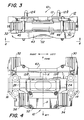
- Fig. 3 is a front elevational view taken on line 3-3 of Fig. 2, the view looking rearward, or aft, relative to the direction of motion of the aircraft;
- Fig. 4 is a plan view taken on line 4-4 of Fig. 3, the view looking upward at the engine mounting bracket assembly from below when installed on an aircraft;
- Fig. 5 is an exploded perspective view of the engine mounting bracket assembly of the present invention;
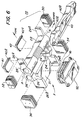
- Fig. 6 is an exploded perspective view of the lower portion of the assembly illustrated in Fig. 5; and
- Fig. 7 is an enlarged, partially-sectioned, transverse sectional view illustrating the manner in which the engine mounting assembly of the present invention is connected to a turbine engine hanger.
- Referring now to the drawings, Fig. 1 illustrates somewhat schematically an aircraft turbine engine (E) suspended from an engine strut (S) located below an aircraft wing (W). The engine E is normally fastened to the wing structures by fore and aft engine mounting assemblies. The present invention is concerned with the aft engine mounting assembly schematically indicated within the encircled area of Fig. 1 which is denominated Fig. 2.
- As illustrated in Fig. 2, the
engine mounting assembly 10 of the present invention is shown separate from the engine strut S and the engine E. Themounting assembly 10 includes abase 12 which is adapted to be fastened against the bottom surface of a suitably-shaped structural member carried on the bottom of the engine strut structure S. A pair ofalignment pins 12a, 12b project upwardly from thebase 12 to facilitate alignment of thebase 12 during installation. Thebase 12 is connected to the engine strut S by high strength bolts (not shown). - In the disclosed embodiment, the
mounting assembly 10 is mounted to the aircraft in the manner illustrated in Fig. 2 with the forward direction of movement of the aircraft being indicated by the arrow denominated "fore" and the opposite, or rearward, direction being denominated by the arrow indicated "aft". As used herein, the terms "lateral" and "transverse" refer to directions perpendicular to the plane of the sheet of Fig. 2. The term "vertical" is indicated by the arrows denominated "up" and "down" running the lengthwise direction of the sheet containing Figs. 1 and 2. With reference to Fig. 7, the lateral direction is indicated by the arrows. The fore direction is perpendicular to the plane of Fig. 7, away from the viewer. In other words, Fig. 7 is a view looking forward in Fig. 1. - As best seen in Fig. 7, the mounting assembly base means 12 is mounted intermediate the aircraft engine mounting structure S and the aircraft engine hanger (H). The hanger H has upstanding left and right lugs H₁, H₂, respectively which project upwardly into recesses R₁, R₂ respectively in the
base 12. The recesses R₁, R₂ are located inward of a pair of left and right dependingflanges base 12. The hanger lugs H₁, H₂ are fastened to themounting assembly 10 by means oftransverse pin assemblies - The configuration of the
base 12 may best be seen by reference to Fig. 5 which is an exploded perspective view looking upward toward themounting assembly 10 as it is installed below an aircraft wing but with connecting bolts removed for purposes of clarity and with an engineattachment bracket assembly 22 displaced downwardly so that interior details of thebase 12 may be viewed more readily. Thebase 12 includes a main generally horizontally-disposed planar plate-like portion 13 from which downturned flange means 14 and 16 depend along left and right sides respectively. The flange means, such as theleft flange 14, has fore andaft surfaces 14a, 14b which confront similarly locatedsurfaces 16a, 16b on its companionright flange 16. In the embodiment illustrated, the forward flanges 14a, 16a are spaced apart further from one another than therearward surfaces - A pair of
lugs 13a, 13b depend from themain portion 13 of the base means 12 in spaced parallel relation inward of theflanges lugs 13a, 13b have transverse aligned through bores which are in registry with throughbores 14′, 16′ in the left andright flanges lugs 13a, 13b andbored flanges mounting assembly 10. - Various vertically-disposed holes are provided in the
base 12 for receiving bolts (not shown) to enable thebase 12 to be connected to the aircraft engine mounting strut S in a conventional manner. The various connecting bolts have been omitted from Fig. 5 for clarity. Preferably, theentire base 12, including theflanges lugs 13a, 13b, is of monolithic construction, being machined from a one piece block of high-strength metal, such as Type 15-5 PH stainless steel. - For the purpose of connecting the engine hanger H to the mounting
base 12, the engineattachment bracket assembly 22 is provided. As best seen in Fig. 5, the engineattachment bracket assembly 22 fits within the confines of thebase flanges main plate portion 13 of thebase 12. When thus assembled, the engineattachment bracket assembly 22 cooperates with the base 12 to provide a relatively low profile, compact mount configuration such as illustrated in Fig. 3. As best seen in Fig. 4, which is a view looking upward in Fig. 3, the engine hanger lugs H₁, H₂ are disposed laterally inward alongside the dependingflanges lugs 13a, 13b. - The engine attachment bracket assembly indicated generally at 22 in Fig. 5 comprises several components. As best seen in Fig. 6, the
attachment bracket assembly 22 includes a pair ofarms arms torque tube 28 having a bore 28' extending along its longitudinal axis A-A. In the present instance, the first defined location is located forward of the engine hanger, but there may be installations in which it may be desirable for the location of thetorque tube 28 to be aft. - The
arms tie brace 31 extending between the arms along their upper edges. Thetie brace 31 is stiff, but slightly flexible, to interconnect the arms in a manner that permits a slight amount of relative pivotal motion about the torque tube axis A-A. Thearms arms torque tube 28. Thus, thearms torque tube 28 and thetie brace 31 to form an open, generally rectangular frame F (Fig. 6) which is disposed in substantially parallel relation with the base plate 13 (FIG. 7). Thearms bores 24′, 26′ which are aligned with corresponding bores in the engine hanger lugs H₁, H₂. Thebores 14′, 16′ in theflanges lugs 13a and 13b are enlarged to provide a vertical clearance permitting the lugs H₁, H₂ to move vertically through limited distances in the recesses R₁, R₂ when thearms pin assemblies - For the purpose of mounting the frame F to the base 12 in a manner permitting the
frame arms torque tube 28, elastomeric bearing means is provided. As best seen in Fig. 6, the elastomeric bearing means includes a pair of upper arcuate laminated elastomeric bearing portions 40a, 42a embracing the upper side of thetorque tube 28 and a diametrically opposite complementary pair of laminatedelastomeric bearing portions 40b, 42b embracing the underside of thetorque tube 28. The upper pair of elastomeric bearing portions 40a and 42a haveelongate bosses base plate 13. The lower pair of bearingportions 40b, 42b are similarly shaped and received by anelongate retainer 43 which extends lengthwise below thetorque tube 28. Each of the bearing portions may include alternating layers of elastomeric material bonded to and between arcuate shims. Theretainer 43 is fastened to thebase plate 13, by fasteners, such as the pair offasteners fasteners elastomeric bearings 40a, 42a, and 40b, 42b in accordance with customary practice. Desirably, the elastomeric bearing portions are bonded to thetorque tube 28 on their diametrically opposite sides so as to carry load in shear without sliding. Thus, the torque tube elastomeric bearings permit thearms arms - The
arms torque tube 28 and thetie brace 31 so that they move substantially in unison with one another as they pivot about the torque tube axis A-A. Some limited amount of independent arm deflection relative to one another is, however, accommodated by flexure of thetie brace 31. It is for this purpose that thetie brace 31 is relatively thin in the vertical direction. - To allow arm motion required for achieving a specified vertical spring rate, and to provide additional support for the frame F, a vibration isolator means 50 is provided. As best seen in the embodiment illustrated in Fig. 6, the vibration isolator means 50 includes a main laminated elastomeric bearing pad assembly which engages the underside of the
tie brace 31 and which is supported by anunderlying support cap 52. Thesupport cap 52 is secured to theplate portion 13 of the base 12 by a plurality of mounting studded spacers (not shown). - In the present instance, the engine hanger lugs H₁, H₂ are attached to the
arms torque tube 28 than the vibrationisolator pad assembly 50 although this need not occur in all applications. The unequal distances between the attachment points and the fore and aft frame bearings provide a desirable leverage action. Thus, for instance, one portion of the load carried by the frame F is transferred to thebase 12 by theisolator pad 50, and another portion of the load carried by the frame F is transferred by the torque tube elastomeric bearings described heretofore. The load is thereby shared. - The relative loading of the front and rear elastomeric assemblies provides a number of advantages. For instance, by locating the point of engine attachment between the pivot bearings and the
isolator pad 50, the heavy vertical load from the engine weight is divided between these elastomeric elements, allowing all of them to be smaller in size. In previous designs, vertical load is reacted by a cocking loading of elastomer pads bonded to a shaped torque tube. In the present invention, cocking loading is eliminated. Instead, radial loads are applied to elastomeric pivot bearings, and nearly uniform, more efficient, compression loads are applied to the isolator pad. The elastomeric bearings are designed to be very stiff radially so as to be able to carry their share of vertical load without over strain. The isolator pad can be made relatively large in length and width for low compression stress, and thick for low compression strains, without compromising spring rate. The low compression stress also allows the use of a soft (low modulus) elastomer, which provides lower set and drift, less hysteresis damping, and a lower dynamic-to-static stiffness ratio. The result is increased service life, better vibration isolation, and less engine motion than other concepts having the same dynamic spring rates could provide. - While relatively soft elastomers may be utilized in the
pad 50, alternating with layers of inelastic material, such as the horizontally-disposed metal shims, thevibration isolator pad 50 may incorporate a fluid isolator which can be designed to either actively or passively provide further improved vibration isolation within a predetermined range of engine operating frequencies. Such an isolator may be designed, for example, to provide vibration and noise attenuation while the engine is operating at cruise power settings to minimize noise in the aircraft. The particular manner by which the desired vibrator isolation can be achieved is well known to designers of fluid mounts. Fluid mounts provide the advantage of enabling higher vertical and lateral static spring rates to be achieved without compromising isolation at desired operating frequencies. - In order to control lateral motion of the frame F relative to the
base 12, while permitting the aforedescribed motions of thearms base flanges pads torque tube 28 and a pair ofpads tie brace 31. Preferably thepads pads - Fluid mounts could also be substituted for the lateral auxiliary
elastomeric bearing assemblies lateral pads base 12. - In operation, downward static loads imparted to the
arms aft pad assemblies arms arms tie brace 31 to compress theisolator pad 50, and motion in the opposite direction relieves such compression. Extreme up or down excursion of thearms pins lugs lateral pads arms pad 50 to support most of the down load at that location. When reacting engine roll moment about the longitudinal axis of the engine E, thearms arms tie brace 31 by virtue of its thinness in the vertical direction. For vertical engine motion witharms torque tube 28 is accommodated by its associated axially-spaced elastomeric bearings due to the ability of the elastomeric layers of the bearings to undergo shearing among the inelastic layers thereof. - By way of example, and not by way of limitation, the elastomers composing the various elastomeric bearings should be heat resistant. A preferred elastomer is type SPE® V manufactured by Lord Corporation of Erie, PA, the assignee of the present invention. The elastomeric elements used in the pivot bearings may have, and preferably have, a radial spring rate which is about 100 times as stiff as the
isolator compression pad 50, but contribute less than 1% of the vertical spring rate at the hanger attachment. Other desirable characteristics of the elastomers include:
a metallic discontinuity (low modulus) connection between engine and airframe for high frequency noise attenuation, and a very gradual change in spring rate after the onset of elastomer fatigue that allows visual "on-condition" replacement criteria. For a typical aft engine mounting load requirement of 4,546 Kg (10,000 lbs) a combined vertical spring rate of 122,638 nt/cm (70,000 lb/in) measured at the hanger attachment is desirable, 10% contributed by the forward pads and bearings, and 90% from the aft pad. Combined lateral spring rates of 122,638 nt/cm (70,000 lb/in), divided 30% fore and 70% aft are also desirable. Loss factors (tan delta) in a range of .05 to .30 are desirable for the chosen elastomers. - In view of the foregoing, it should be apparent that the present invention now provides a turbine engine mounting assembly which is well suited for heavy duty applications and for applications requiring improved lateral and vertical vibration isolation without as much allowed engine motion as is available with known mounts. Since the mounting bracket assembly utilizes known materials and state of the art manufacturing techniques, it can be designed to meet a variety of operational requirements, yet can be assembled in a straightforward manner and refurbished readily, if necessary.
- In the disclosed embodiment, the engine strut below the wing W provides one structure and the engine hanger lugs another structure which are interconnected by means of the mounting assembly of the present invention. There may, however, be other applications in which the disclosed embodiment may find utility such as in various types of systems involving the mounting of vibratory prime movers to various types of supports. An important aspect of the disclosed embodiment is the interposition of elastomeric materials in the load path between the engine structure and its support structure to provide vibration isolation.
- In the disclosed embodiment, the arms extend in parallel relation from the torque tube, but in some applications they may converge or diverge. The ends of the arms can be interconnected by tie means, other than the metal tie brace shown, provided the requisite function is realized. The frame also need not in all instances be pivotally supported by the torque tube bearings, but could be supported pivotally at a location separated from the torque tube axis. The torque tube is, however, required. While the hanger lugs connect to the arms between the torque tube and main isolator pad, there may be applications where the arms could be extended fore or aft of either the torque tube and the main isolator pad and attachment made to the arm extensions. Accordingly, while the embodiment disclosed is the best mode contemplated by the applicants at this time, it is not to be regarded as limiting.
- Thus, while a preferred embodiment of the present invention has been described in detail, various modifications, alterations and changes may be made without departing from the scope of the invention as defined in the appended claims.
Claims (8)
- A mounting assembly (10) for use in connecting, and isolating vibration between, two spaced apart structures (S,E), including
a pair of arms (24,26) disposed in spaced relation alongside one another between said structures (S,E),
means (28,31) for providing a torsional connection between said arms (24,26) to restrain motion relative to one another about an axis (A-A) extending transverse to the arms (24,26) at a first location, means (12) for mounting said arms (24,26) to one (S) of said structures in a manner permitting the arms (24,26) to pivot about said axis (A-A) either in unison or independently of one another,
means (18,20) for connecting said arms (24,26) to the other (E) of said structures at a second location spaced from said axis (A-A), said mounting assembly being characterized by
means (50) providing a main vibration isolation connection between said arms (24,26) and said one (S) of said structures at a third location spaced from said pivot axis (A-A),
whereby the structures (S,E) are connected together in a manner that minimizes the transmission of vibrations between them. - A mounting assembly according to Claim 1 being further characterized by flange means (14,16) on said means (12) for mounting said arms (24,26) on said one (S) of said structures extending alongside at least portions of said arms, and auxiliary vibration isolation means (30,32,34,36) disposed between said arm portions and said flange means for restraining motion of said arms along said pivot axis (A-A) while accommodating said pivotal motion of said arms about said pivot axis.
- A mounting assembly according to Claim 2 being further characterized by said auxiliary vibration isolation means (30,34; 32,36) being disposed so that its elastic center extends through said second location.
- A mounting assembly according to Claim 2 or Claim 3 being further characterized by said flange means (14,16) extending in spaced parallel adjacent relation along opposite sides of said arms, and said auxiliary vibration isolation means including a pair (30,34; 32,36) of resilient pads disposed between each arm (24,26) and its adjacent flange means.
- A mounting assembly according to any one of Claims 1 to 4 being further characterized by said means providing said main vibration isolation connection including means (31,50,52) for resiliently connecting said arms to said one of said structures in a manner restraining substantial relative movement both between the arms and between the arms and said one structure at said third location.
- A mounting assembly according to Claim 5 being further characterized by said means for resiliently connecting said arms including a tie brace (31) connecting said arms together at said third location, a resilient compression pad assembly (50) engaging said tie brace, and cap means (52) engaging said resilient compression pad for connecting it to said one structure, whereby motion of the arms away from said one structure is reacted in compression by said resilient compression pad.
- A mounting assembly according to any of the Claims 1 to 6 being further characterized by said arms (24,26), said torsional connecting means (28) and said main vibration isolation connection (50) cooperate to form an open frame (F) disposed between said structures (S,E), and said means for mounting said arms to said one of said structures including an elastomeric bearing assembly (40a,40b,42a,42b).
- A mounting assembly according to any one of Claims 1 to 5 being further characterized by said arms (24,26) extending in spaced relation and being interconnected at said first location by a torque tube (28) which provides said torsional connection means; and said means providing said main vibration isolation connection including a tie brace (31) interconnecting said arms at said third location, a resilient compression pad (50) engaging said tie brace, and cap means (52) connecting said pad to said one of said structures (S), whereby arm motion is reacted in compression by said resilient pad.
Applications Claiming Priority (2)
| Application Number | Priority Date | Filing Date | Title |
|---|---|---|---|
| US07/514,071 US5108045A (en) | 1990-04-25 | 1990-04-25 | Engine mounting assembly |
| US514071 | 1995-08-11 |
Publications (2)
| Publication Number | Publication Date |
|---|---|
| EP0455355A1 EP0455355A1 (en) | 1991-11-06 |
| EP0455355B1 true EP0455355B1 (en) | 1994-11-30 |
Family
ID=24045682
Family Applications (1)
| Application Number | Title | Priority Date | Filing Date |
|---|---|---|---|
| EP91303058A Expired - Lifetime EP0455355B1 (en) | 1990-04-25 | 1991-04-08 | Engine mounting assembly |
Country Status (4)
| Country | Link |
|---|---|
| US (1) | US5108045A (en) |
| EP (1) | EP0455355B1 (en) |
| CA (1) | CA2038621C (en) |
| DE (1) | DE69105345T2 (en) |
Families Citing this family (23)
| Publication number | Priority date | Publication date | Assignee | Title |
|---|---|---|---|---|
| US6022600A (en) * | 1992-04-24 | 2000-02-08 | Lord Corporation | High-temperature fluid mounting |
| US5351930A (en) * | 1992-08-11 | 1994-10-04 | Lord Corporation | Mounting for engines and the like |
| FR2738034B1 (en) * | 1995-08-23 | 1997-09-19 | Snecma | DEVICE FOR SUSPENDING A TURBOPROPELLER |
| US5687948A (en) * | 1995-09-26 | 1997-11-18 | Lord Corporation | Vibration isolation system including a passive tuned vibration absorber |
| US6065742A (en) | 1996-09-13 | 2000-05-23 | Lord Corporation | Multi-directional tuned vibration absorber |
| US5845236A (en) * | 1996-10-16 | 1998-12-01 | Lord Corporation | Hybrid active-passive noise and vibration control system for aircraft |
| US5957440A (en) | 1997-04-08 | 1999-09-28 | Lord Corporation | Active fluid mounting |
| US6113030A (en) * | 1997-11-17 | 2000-09-05 | Lord Corporation | Readily changeable isolator and method of assembly thereof |
| US6328293B1 (en) | 1998-09-18 | 2001-12-11 | Lord Corporation | Multi-linkage suspension system including outboard isolators |
| US7104306B2 (en) * | 2004-06-14 | 2006-09-12 | The Boeing Company | Cast unitized primary truss structure and method |
| GB0507721D0 (en) * | 2005-04-16 | 2005-05-25 | Rolls Royce Plc | Gas turbine engine mounting arrangement |
| WO2008091376A2 (en) * | 2006-07-25 | 2008-07-31 | Lord Corporation | Tiltrotor aircraft drivelink |
| FR2914907B1 (en) * | 2007-04-16 | 2009-10-30 | Snecma Sa | SOFT SUSPENSION WITH COMB FOR TURBOMOTEUR |
| US7966921B1 (en) * | 2009-04-01 | 2011-06-28 | The United States Of America As Represented By The Secretary Of The Navy | Aircraft wing-pylon interface mounting apparatus |
| FR2947528B1 (en) * | 2009-07-03 | 2011-06-24 | Airbus Operations Sas | ATTACHMENT SYSTEM FOR A PROPELLER ENGINE |
| US7784773B1 (en) | 2009-08-04 | 2010-08-31 | Itt Manufacturing Enterprises, Inc. | Isolator useful for in-line mounting with a strut |
| US9617918B2 (en) * | 2014-01-13 | 2017-04-11 | The Boeing Company | Bracket for mounting/removal of actuators for active vibration control |
| US9174739B2 (en) | 2014-01-13 | 2015-11-03 | The Boeing Company | Active vibration control system |
| US10161309B2 (en) | 2015-02-10 | 2018-12-25 | United Technologies Corporation | Thermally compliant fitting for high temperature tube applications |
| US10220951B2 (en) * | 2016-02-01 | 2019-03-05 | Bell Helicopter Textron Inc. | Sleeved bolt assemblies for aircraft engine mount assemblies |
| US20210284348A1 (en) | 2016-08-08 | 2021-09-16 | Lord Corporation | Mounting systems, devices, and methods for aircraft engines |
| CN109592051A (en) * | 2018-12-03 | 2019-04-09 | 江西洪都航空工业集团有限责任公司 | A kind of engine installation structure |
| EP3663206B1 (en) * | 2018-12-06 | 2023-09-06 | AIRBUS HELICOPTERS DEUTSCHLAND GmbH | An attachment for suspending an aircraft engine |
Family Cites Families (12)
| Publication number | Priority date | Publication date | Assignee | Title |
|---|---|---|---|---|
| FR821528A (en) * | 1936-08-07 | 1937-12-07 | D Aviat Louis Breguet Sa Des E | Elastic suspension of aircraft engines |
| US2197081A (en) * | 1937-06-14 | 1940-04-16 | Transit Res Corp | Motor support |
| US2891743A (en) * | 1954-06-08 | 1959-06-23 | Textron Inc | Airplane engine suspension and mounts therefor |
| US3168270A (en) * | 1963-02-11 | 1965-02-02 | Cal Val Res & Dev Corp | Engine mount |
| US3288404A (en) * | 1964-08-24 | 1966-11-29 | Lord Corp | Engine mounting system |
| US3747879A (en) * | 1972-02-23 | 1973-07-24 | Gen Motors Corp | Engine mount |
| WO1985002596A1 (en) * | 1983-12-08 | 1985-06-20 | The Boeing Company | Aft engine mount |
| US4634081A (en) * | 1983-12-30 | 1987-01-06 | The Boeing Company | Aft engine mount with vibration isolators |
| US4717094A (en) * | 1986-05-19 | 1988-01-05 | The Boeing Company | Aircraft engine mount system with vibration isolators |
| US4725019A (en) * | 1986-08-11 | 1988-02-16 | The Boeing Company | Aircraft engine mount with vertical vibration isolation |
| US4805851A (en) * | 1987-08-10 | 1989-02-21 | Herbst Paul T | Turbine engine mounting bracket assembly |
| FR2638799B1 (en) * | 1988-11-09 | 1991-01-25 | Hutchinson | ELASTIC SUPPORT WITH ANISOTROPIC STRAINERS, PARTICULARLY FOR SUSPENSION OF BODYWORK |
-
1990
- 1990-04-25 US US07/514,071 patent/US5108045A/en not_active Expired - Lifetime
-
1991
- 1991-03-19 CA CA002038621A patent/CA2038621C/en not_active Expired - Fee Related
- 1991-04-08 EP EP91303058A patent/EP0455355B1/en not_active Expired - Lifetime
- 1991-04-08 DE DE69105345T patent/DE69105345T2/en not_active Expired - Fee Related
Also Published As
| Publication number | Publication date |
|---|---|
| CA2038621A1 (en) | 1991-10-26 |
| DE69105345T2 (en) | 1995-04-27 |
| EP0455355A1 (en) | 1991-11-06 |
| DE69105345D1 (en) | 1995-01-12 |
| CA2038621C (en) | 2003-05-27 |
| US5108045A (en) | 1992-04-28 |
Similar Documents
| Publication | Publication Date | Title |
|---|---|---|
| US5108045A (en) | Engine mounting assembly | |
| US4725019A (en) | Aircraft engine mount with vertical vibration isolation | |
| US4805851A (en) | Turbine engine mounting bracket assembly | |
| EP1113959B1 (en) | Multi-linkage suspension system including outboard isolators | |
| EP0583158B1 (en) | Mounting for engines and the like | |
| US6431530B1 (en) | Vertical liquid inertia vibration isolator | |
| US8215606B2 (en) | Variable stiffness support | |
| US5176339A (en) | Resilient pivot type aircraft mounting | |
| EP1115614B1 (en) | Fluid damper including flexible damping plate | |
| EP0629791A1 (en) | Fluid mount for engines and the like | |
| WO1992021912A1 (en) | Vibration isolation system | |
| JPS6249239B2 (en) | ||
| US7900873B2 (en) | Vibration isolation system | |
| EP1671047B1 (en) | Vibration mounting | |
| US4365771A (en) | Inplane nodalization system | |
| US11427308B2 (en) | Attachment of a landing gear | |
| US6871820B2 (en) | Aircraft engine mounting | |
| US5523530A (en) | Elastomeric acoustic insulator | |
| US2891743A (en) | Airplane engine suspension and mounts therefor | |
| US3056569A (en) | Airplane engine suspension system | |
| EP2894098B1 (en) | Bracket for Mounting/Removal of Actuators for Active Vibration Control | |
| CA1142155A (en) | Inplane nodalization system | |
| US12227289B2 (en) | Rotorcraft provided with an airframe carried by a skid landing gear with zones for taking up variable forces |
Legal Events
| Date | Code | Title | Description |
|---|---|---|---|
| PUAI | Public reference made under article 153(3) epc to a published international application that has entered the european phase |
Free format text: ORIGINAL CODE: 0009012 |
|
| AK | Designated contracting states |
Kind code of ref document: A1 Designated state(s): DE FR GB IT |
|
| 17P | Request for examination filed |
Effective date: 19920427 |
|
| 17Q | First examination report despatched |
Effective date: 19930623 |
|
| GRAA | (expected) grant |
Free format text: ORIGINAL CODE: 0009210 |
|
| AK | Designated contracting states |
Kind code of ref document: B1 Designated state(s): DE FR GB IT |
|
| ITF | It: translation for a ep patent filed | ||
| REF | Corresponds to: |
Ref document number: 69105345 Country of ref document: DE Date of ref document: 19950112 |
|
| ET | Fr: translation filed | ||
| PLBE | No opposition filed within time limit |
Free format text: ORIGINAL CODE: 0009261 |
|
| STAA | Information on the status of an ep patent application or granted ep patent |
Free format text: STATUS: NO OPPOSITION FILED WITHIN TIME LIMIT |
|
| 26N | No opposition filed | ||
| REG | Reference to a national code |
Ref country code: GB Ref legal event code: IF02 |
|
| PGFP | Annual fee paid to national office [announced via postgrant information from national office to epo] |
Ref country code: FR Payment date: 20020319 Year of fee payment: 12 |
|
| PGFP | Annual fee paid to national office [announced via postgrant information from national office to epo] |
Ref country code: GB Payment date: 20020403 Year of fee payment: 12 |
|
| PGFP | Annual fee paid to national office [announced via postgrant information from national office to epo] |
Ref country code: DE Payment date: 20020418 Year of fee payment: 12 |
|
| PG25 | Lapsed in a contracting state [announced via postgrant information from national office to epo] |
Ref country code: GB Free format text: LAPSE BECAUSE OF NON-PAYMENT OF DUE FEES Effective date: 20030408 |
|
| PG25 | Lapsed in a contracting state [announced via postgrant information from national office to epo] |
Ref country code: DE Free format text: LAPSE BECAUSE OF NON-PAYMENT OF DUE FEES Effective date: 20031101 |
|
| GBPC | Gb: european patent ceased through non-payment of renewal fee |
Effective date: 20030408 |
|
| PG25 | Lapsed in a contracting state [announced via postgrant information from national office to epo] |
Ref country code: FR Free format text: LAPSE BECAUSE OF NON-PAYMENT OF DUE FEES Effective date: 20031231 |
|
| REG | Reference to a national code |
Ref country code: FR Ref legal event code: ST |
|
| PG25 | Lapsed in a contracting state [announced via postgrant information from national office to epo] |
Ref country code: IT Free format text: LAPSE BECAUSE OF NON-PAYMENT OF DUE FEES;WARNING: LAPSES OF ITALIAN PATENTS WITH EFFECTIVE DATE BEFORE 2007 MAY HAVE OCCURRED AT ANY TIME BEFORE 2007. THE CORRECT EFFECTIVE DATE MAY BE DIFFERENT FROM THE ONE RECORDED. Effective date: 20050408 |