EP0454768B1 - Ball valve - Google Patents
Ball valve Download PDFInfo
- Publication number
- EP0454768B1 EP0454768B1 EP90902501A EP90902501A EP0454768B1 EP 0454768 B1 EP0454768 B1 EP 0454768B1 EP 90902501 A EP90902501 A EP 90902501A EP 90902501 A EP90902501 A EP 90902501A EP 0454768 B1 EP0454768 B1 EP 0454768B1
- Authority
- EP
- European Patent Office
- Prior art keywords
- ball valve
- stem
- shoulder
- adjacent
- metal
- Prior art date
- Legal status (The legal status is an assumption and is not a legal conclusion. Google has not performed a legal analysis and makes no representation as to the accuracy of the status listed.)
- Expired - Lifetime
Links
Images

Classifications
-
- F—MECHANICAL ENGINEERING; LIGHTING; HEATING; WEAPONS; BLASTING
- F16—ENGINEERING ELEMENTS AND UNITS; GENERAL MEASURES FOR PRODUCING AND MAINTAINING EFFECTIVE FUNCTIONING OF MACHINES OR INSTALLATIONS; THERMAL INSULATION IN GENERAL
- F16K—VALVES; TAPS; COCKS; ACTUATING-FLOATS; DEVICES FOR VENTING OR AERATING
- F16K5/00—Plug valves; Taps or cocks comprising only cut-off apparatus having at least one of the sealing faces shaped as a more or less complete surface of a solid of revolution, the opening and closing movement being predominantly rotary
- F16K5/06—Plug valves; Taps or cocks comprising only cut-off apparatus having at least one of the sealing faces shaped as a more or less complete surface of a solid of revolution, the opening and closing movement being predominantly rotary with plugs having spherical surfaces; Packings therefor
- F16K5/0663—Packings
- F16K5/0694—Spindle sealings
-
- F—MECHANICAL ENGINEERING; LIGHTING; HEATING; WEAPONS; BLASTING
- F16—ENGINEERING ELEMENTS AND UNITS; GENERAL MEASURES FOR PRODUCING AND MAINTAINING EFFECTIVE FUNCTIONING OF MACHINES OR INSTALLATIONS; THERMAL INSULATION IN GENERAL
- F16K—VALVES; TAPS; COCKS; ACTUATING-FLOATS; DEVICES FOR VENTING OR AERATING
- F16K41/00—Spindle sealings
- F16K41/02—Spindle sealings with stuffing-box ; Sealing rings
- F16K41/04—Spindle sealings with stuffing-box ; Sealing rings with at least one ring of rubber or like material between spindle and housing
- F16K41/043—Spindle sealings with stuffing-box ; Sealing rings with at least one ring of rubber or like material between spindle and housing for spindles which only rotate, i.e. non-rising spindles
- F16K41/046—Spindle sealings with stuffing-box ; Sealing rings with at least one ring of rubber or like material between spindle and housing for spindles which only rotate, i.e. non-rising spindles for rotating valves
-
- F—MECHANICAL ENGINEERING; LIGHTING; HEATING; WEAPONS; BLASTING
- F16—ENGINEERING ELEMENTS AND UNITS; GENERAL MEASURES FOR PRODUCING AND MAINTAINING EFFECTIVE FUNCTIONING OF MACHINES OR INSTALLATIONS; THERMAL INSULATION IN GENERAL
- F16K—VALVES; TAPS; COCKS; ACTUATING-FLOATS; DEVICES FOR VENTING OR AERATING
- F16K5/00—Plug valves; Taps or cocks comprising only cut-off apparatus having at least one of the sealing faces shaped as a more or less complete surface of a solid of revolution, the opening and closing movement being predominantly rotary
- F16K5/06—Plug valves; Taps or cocks comprising only cut-off apparatus having at least one of the sealing faces shaped as a more or less complete surface of a solid of revolution, the opening and closing movement being predominantly rotary with plugs having spherical surfaces; Packings therefor
- F16K5/0663—Packings
- F16K5/0668—Single packings
Definitions
- This invention relates to a ball valve and more particularly to an improved metal seat design for a so-called floating ball valve.
- Floating ball valves include a spherical ball valve member mounted within a valve chamber of the valve body for limited floating movement between upstream and downstream seats on opposed sides of the ball valve member.
- a floating ball valve moves in a direction along the longitudinal axis of the flow passages between opposed seats and is limited by such seats to a relatively small predetermined axial movement.
- the object of the invention is to provide a ball valve of the recited type providing improved sealing at both low and high fluid pressures.
- a ball valve having a valve body chamber with a floating ball valve member mounted therein for movement between open and closed positions, and an annular recess about a flow passage in the valve body adjacent the flow chamber defining an outer circumferential surface and an adjacent planar shoulder extending in a generally radial direction; and a one piece annular metal seat fitting within said annular recess about said flow passage adapted for contacting the adjacent spherical surface of the floating ball valve member, whereby that said metal seat comprises a body portion of a generally uniform thickness extending in a generally radial direction in opposed relation to the adjacent planar shoulder and defining an inner low pressure lip about its inner circumference contacting the adjacent spherical surface of the floating ball member in sealing relation during the entire operation of said ball valve; and a bearing portion integrally connected to said body portion and extending therefrom in a direction generally parallel to the longitudinal axis of the flow passage, said bearing portion having a seat adjacent the spherical surface of the floating ball
- a relatively small thickness connecting portion of the seat which extends between the body portion and the bearing portion flexes upon the ball valve member engaging the bearing portion at high pressure conditions and exerts a seating force against the body portion for tightly sealing the rear surface of the body portion against the rear shoulder of the recess in metal-to-metal relation.
- the bearing portion of the metal seat is spaced from the ball valve member a distance less the spacing of the lip from the shoulder of the recess thereby to protect the lip from excessive force exerted by the ball valve member under very high fluid pressures.
- the body portion of the metal seat acts in a manner similar to a Belleville spring and its inner lip provides sealing against the ball valve member at low fluid pressure as low as around 6-8 kPa (1 psi) while spaced from the adjacent shoulder of the recess.
- valve stem mounting means in which aligned openings in the valve body and the outer plate for receiving the stem include an inner packing about the stem and an adjacent Belleville washer exerting a continuous generally uniform compressive loading against the packing.
- valve stem mounting system is disclosed in US-A-2 981 284 according to which the stem has a shoulder between its ends.
- the oppositely facing shoulder surfaces are in engagement with bearing rings fitted in the valve body and a valve body cap, respectively.
- the opening in the outer plate outwardly of the Belleville washer and packing has an outer thrust bearing therein about the stem and is compressed independently of the packing under a predetermined light loading between a stem shoulder and the outer plate by an adjusting nut threaded onto the stem.
- the thrust bearing may be easily inserted or replaced without disassembly of the packing and is not exposed to loading within the valve chamber since mounted outwardly of the packing.
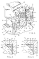
- a spherical plug or ball valve comprising this invention is indicated generally at 10 including a main body portion 14 and an end body portion 12 by a plurality of threaded bolts 16.
- flanges 18 of a flowline 19 fit on opposed ends 20 of body portions 12 and 14 and nut and bolt combination 22 clamp ball valve structure 10 tightly therebetween.
- Body portion 14 has an inlet opening 24 and body portion 12 has an outlet opening 26.
- An inlet flow passage is indicated at 28 and an outlet flow passage is indicated at 30.
- Body portions 12 and 14 define an enlarged diameter valve chamber at 32 and a ball valve member 34 is mounted within chamber 32 for floating movement.
- a stem generally indicated at 36 has a handle 38 mounted thereon and is adapted to rotate ball valve member 34 between open and closed positions relative to flow line 19.
- Ball valve member 34 has a spherical outer surface 40 and a central bore 42 therethrough which is in axial alignment with the longitudinal axis of flow passages 28 and 30 in open position.
- a slot 44 is provided in the upper surface of ball member 34.
- Stem 36 has a lower end 46 fitting within slot 30 and permitting longitudinal movement of ball member 34 in the closed position thereof. Coacting flats defined by slot 44 and lower end 46 effect rotation of ball member 34 upon rotation of stem 36.
- Stem 36 includes an intermediate large diameter stem section 48 adjacent lower end 46, an intermediate diameter stem section 50 adjacent stem section 48 defining an annular shoulder 52 therebetween a cylindrical threaded section 54 adjacent stem section 50, and an upper end threaded section 56 adjacent cylindrical threaded section 54.
- Upper end threaded section 56 has a pair of opposed planar or flat surfaces 58 connected by arcuate externally threaded surfaces 60.
- Valve body portion 12 has an upper opening or bore receiving valve stem 36 defining a small diameter intermediate portion 62, an intermediate diameter inner portion 64, and an enlarged diameter outer portion 66.
- a flange 68 is formed between intermediate bore portion 64 and large diameter bore portion 66.
- a collar 70 integral with stem 70 is spaced from flange 68 and remains spaced from flange 68 even under the application of high fluid pressures within valve chamber 32.
- an outer clamp plate 72 is secured to body portion by a plurality of threaded bolts 74.
- Plate 72 has a bore therethrough defining an inner large diameter bore portion 78, and an outer small diameter bore portion 80.
- a packing 82 fits within enlarged diameter bore portion 66 of body portion 12 about large diameter stem section 48.
- a follower 84 is positioned over the outer end of packing and a pair of Belleville washers 86 fitting within large diameter bore portion 76 of plate 72 are positioned between follower 84 and plate 72 for continuously exerting a downward or inner force against follower 84.
- Washers 86 have inner marginal portions 87 exerting a downward force on follower 84 and outer marginal portions 89 exerting an opposed force on plate 72 with follower 84 compressing packing 82 between shaft 36 and body portion 12. Washers 86 are of an outer diameter substantially larger than the outer diameter of packing 82 and exert a pressure on packing 82 greater than the maximum pressure within valve chamber 32 thereby to provide an inner compressive force against packing 82 at all times.
- a thrust ring 88 is mounted within intermediate bore portion 78 of plate 72 and fits against shoulder 52.
- Thrust ring 88 may be formed of a suitable plastic material, such as polytetrafluoroethylene, which will melt or sublimate at a temperature of about 370°C (700°F).
- a nut 90 is threaded onto stem 36 over plate 72 for maintaining a predetermined relationship between thrust ring 88 and shoulder 52. Since stem 36 is rotated relative to thrust ring 88, a relative light loading of thrust ring 88 is normally provided.
- a stop plate 92 had a generally rectangular opening 94 thereon which receives stem 36 and rotates with stem 36 with plate 58 of stem 36.
- a suitable washer 98 and spacer fit over handle 38 and a securing bolt 99 is threaded within an internally threaded opening in the extending end of stem 36 for securing handle 38 thereon.
- Stop plate 92 engages bolts 74 at the fully open and fully closed positions of ball valve member 34.
- Follower 84 exerts a continuously and generally uniform loading against packing 82 even in the event of wear on packing 82 as a result of the force exerted by Belleville springs 86.
- Thrust ring 88 is positioned outwardly of packing 82 and thus controls the position of stem 36 independently of the force applied to packing 82 by Belleville spring 86. Further, thrust ring 88 limits the outward movement of stem 36 upon high fluid pressures in valve chamber 32 and prevents contact of collar 70 with flange 68. However, when thrust ring 88 is consumed by high temperatures, such as may be generated by a fire or the like, stem 36 may be moved upwardly by high pressure within valve chamber 32 with stem collar 70 contacting flange 68.
- Cap screws 74 hold plate 72 tightly against body portion 12 and nut 90 is lightly tightened for providing the desired frictional contact between shoulder 52 and thrust ring 88 upon rotation of ball valve member 34 between open and closed positions.
- the compressive loading of thrust ring 88 can be increased independently of and without compressing packing 82.
- thrust ring 88 can easily be inserted or replaced without removal of packing 82 and is not exposed to ladings within valve chamber 32 which might be corrosive.
- Recesses 100 adjacent valve chamber 32 are provided in the valve body about inlet flow passage 28 and outlet flow passage 30.
- An annular upstream metal seat 102 is mounted in recess 100 about inlet flow passage 28 and an annular downstream metal seat 104 is mounted in recess 100 about outlet flow passage 30.
- Recesses 100 and seats 102, 104 are generally identical and for the purpose of illustration, only the downstream seat 104 is described in detail as shown in Figures 4 and 5.
- recess 110 is defined by an outer peripheral surface 106 which extends in a concentric relation to the longitudinal axis of the associated flow passage and a radial planar surface 108 forms a shoulder extending perpendicularly to surface 106.
- Metal seat 104 of a one-piece metal construction fits within recess 100 adjacent surfaces 106, 108 and comprises a body portion 110 of a generally uniform thickness T between generally parallel planar surfaces 112 and 113 which extend in a generally radial direction.
- Rear planar surface 112 provides a sealing surface against shoulder 108 which at low fluid pressure seals generally at the corner of recess 100 as shown in Figure 4, but at high fluid pressure seals along substantially the entire face of shoulder 108 as shown in Figure 5.
- Body portion 110 acts in a manner similar to a Belleville spring and has a flexible lip 114 at its inner circumference which is rounded at 116 for engaging spherical surface 40 of ball valve member 34. Lip 114 is spaced a distance D from the opposed shoulder 108 during normal operation in the open position of valve member 34 and during low fluid pressure operation in the closed position of ball valve member 34.
- a high pressure flexible seat or bearing portion 118 of metal seat 104 is connected to body portion 110 and has an arcuate bearing or sealing surface 120 adapted to engage adjacent spherical surface 40 of ball valve member 34 under high fluid pressure conditions.
- Seat portion 118 has an outer circumferential surface 122 in opposed relation to outer periphery 106 and arcuate sealing surface 120 is of a contour generally the same as the adjacent spherical surface 40 of ball valve member 34.
- ball valve member 34 is spaced a distance D1 from bearing surface 120 in axial direction parallel to the longitudinal axis of flow passages 28 and 30 as shown in Figure 4.
- Distance D1 under all conditions of operation is less than distance D to act as a stop for ball valve member 34 to minimize wear or damage to lip 114 in forcing lip 114 against shoulder 108.
- D1 may be 0.127mm (.005 inch) and D may be 0.2mm (.008 inch). In any event, D would be at least 0.025mm (.001 inch) greater than D1.
- An outer annular groove 126 in seat 34 defines a connecting portion 128 of seat 34 extending between bearing portion 104 and body portion 110 in a direction generally parallel to the longitudinal axis of the flow passages 28 and 30.
- Connecting portion 128 is flexible and preferably has a generally uniform thickness T1 between around 25% and 65% of the thickness T of body portion 110 with an optimum thickness of around 45% of thickness T.
- connecting portion 128 flexes but yet has sufficient rigidity to exert a strong force against body portion 110 for urging rear sealing surface 112 into tight sealing relation against shoulder 108.
- rounded end 116 is in substantially line contact relation with spherical surface 40 of ball valve member 34 with lip 114 spaced a distance D from adjacent recess shoulder 108, and bearing surface 120 is spaced a distance D1 from the adjacent spherical surface 40 of ball valve member 34.
- Body portion 110 is in metal-to-metal sealing relation with shoulder 108 adjacent the corner of recess 100 formed at the juncture of shoulder 108 with outer circumferential surface 106.
- Metal seal 104 may be formed of various types of corrosion resistant metallic materials, such as a titanium, for example, which has a modulus of elasticity of around 10.3 x 10¹⁰ Pa (15 million psi).
- metal seat 104 while of a substantial strength is relatively flexible in a radial direction between lip 114 and seat portion 118 and will seal adequately even with substantial manufacturing tolerances in shoulder 108 and outer peripheral surface 106 of recess 100.
- bearing surface 120 is contacted by ball valve member 34 before lip 114 engages shoulder 108 to restrain the force exerted against low pressure lip 114 by ball valve member 34.
- Connecting portion 128 transmits the force to body portion 110 for providing a tight sealing force which increases in relation to an increase in fluid pressure.
- Metal seat 104 is particularly adapted for fitting within a recess defined by a pair of body surfaces at right angles to each other.
- a secondary stem seal is provided by collar 70 against flange 68 when high temperature consumes or deteriorates thrust bearing or ring 88 as internal pressure acting against stem 36 forces collar 70 against flange 68 to provide metal to metal engagement.
Abstract
Description
- This invention relates to a ball valve and more particularly to an improved metal seat design for a so-called floating ball valve.
- Floating ball valves include a spherical ball valve member mounted within a valve chamber of the valve body for limited floating movement between upstream and downstream seats on opposed sides of the ball valve member. As compared with so-called trunnion mounted ball valves in which the spherical ball valve member is mounted on upper and lower trunnions for rotation and thus is fixed against any axial movement along the longitudinal axis of the flow passages, a floating ball valve moves in a direction along the longitudinal axis of the flow passages between opposed seats and is limited by such seats to a relatively small predetermined axial movement. As a result, when the ball valve member is in closed position and a high inlet fluid pressure exists, the ball valve member is moved against the downstream seat under a substantial force proportional to the inlet fluid pressure.
- One of the problems associated with metal seat designs for floating ball valves is in the design of a seat which seals effectively at low fluid pressures, such as 34.5 kPa (5 psi), for example, and also seals effectively at high fluid pressures, such as 13.8 MPa (2000 psi), for example.
- Heretofore, various types of metal seats have been provided for floating ball valves including metal seats which shift or rock into a sealing relation upon the application of a high fluid pressure against the ball member, with the seat recess being formed or shaped to accommodate or assist such movement. For example, US-A-4,385,747 shows a metal seat mounted within a recess for facilitating movement of the seat under certain pressure conditions.
- An example of another metal seat construction for a floating ball valve as defined in the precharacterizing portion of independent claim 1 is shown in US-A-4,557,461 which has a metal seal of a substantial solid cross-section with a tapered and flexible lip extending therefrom for sealing against the ball valve member at low temperatures. While the lip is flexible, the remainder of the metal seal does not appear to be flexible to any significant degree.
- The object of the invention is to provide a ball valve of the recited type providing improved sealing at both low and high fluid pressures.
- According to the invention, to achieve this, there is provided a ball valve having a valve body chamber with a floating ball valve member mounted therein for movement between open and closed positions, and an annular recess about a flow passage in the valve body adjacent the flow chamber defining an outer circumferential surface and an adjacent planar shoulder extending in a generally radial direction; and a one piece annular metal seat fitting within said annular recess about said flow passage adapted for contacting the adjacent spherical surface of the floating ball valve member, whereby that said metal seat comprises a body portion of a generally uniform thickness extending in a generally radial direction in opposed relation to the adjacent planar shoulder and defining an inner low pressure lip about its inner circumference contacting the adjacent spherical surface of the floating ball member in sealing relation during the entire operation of said ball valve; and a bearing portion integrally connected to said body portion and extending therefrom in a direction generally parallel to the longitudinal axis of the flow passage, said bearing portion having a seat adjacent the spherical surface of the floating ball member, said seat being spaced from said spherical surface under low pressure operation of said ball valve and contacting said spherical surface in bearing relation under high pressure operation of said valve.
- In one embodiment a relatively small thickness connecting portion of the seat which extends between the body portion and the bearing portion flexes upon the ball valve member engaging the bearing portion at high pressure conditions and exerts a seating force against the body portion for tightly sealing the rear surface of the body portion against the rear shoulder of the recess in metal-to-metal relation. The bearing portion of the metal seat is spaced from the ball valve member a distance less the spacing of the lip from the shoulder of the recess thereby to protect the lip from excessive force exerted by the ball valve member under very high fluid pressures. The body portion of the metal seat acts in a manner similar to a Belleville spring and its inner lip provides sealing against the ball valve member at low fluid pressure as low as around 6-8 kPa (1 psi) while spaced from the adjacent shoulder of the recess.
- In EP-A-0 067 403 there is disclosed a valve stem mounting means in which aligned openings in the valve body and the outer plate for receiving the stem include an inner packing about the stem and an adjacent Belleville washer exerting a continuous generally uniform compressive loading against the packing.
- Another valve stem mounting system is disclosed in US-A-2 981 284 according to which the stem has a shoulder between its ends. The oppositely facing shoulder surfaces are in engagement with bearing rings fitted in the valve body and a valve body cap, respectively.
- In one preferred form of the invention the opening in the outer plate outwardly of the Belleville washer and packing has an outer thrust bearing therein about the stem and is compressed independently of the packing under a predetermined light loading between a stem shoulder and the outer plate by an adjusting nut threaded onto the stem. The thrust bearing may be easily inserted or replaced without disassembly of the packing and is not exposed to loading within the valve chamber since mounted outwardly of the packing.
- Other features and advantages of the invention will become more apparent after referring to the following specification and drawings.
-
- Figure 1 is a longitudinal section view of a ball valve structure comprising the present invention;
- Figure 2 is an end elevation of the ball valve structure shown in Figure 1 taken generally along line 2-2 of Figure 1;
- Figure 3 is an enlarged sectional view in perspective of the upper portion of the valve illustrating the stem and adjacent parts;
- Figure 4 is an enlarged fragment of Figure 1 showing the ball valve member in sealing engagement with the metal seat under a low fluid pressure condition; and
- Figure 5 is a view similar to Figure 4 but showing the ball valve member in engagement with the metal seat under a high fluid pressure condition.
- Referring now to the drawings for a better understanding of this invention, a spherical plug or ball valve comprising this invention is indicated generally at 10 including a
main body portion 14 and anend body portion 12 by a plurality of threadedbolts 16. For connecting ball valves orball valve structure 10 within a flowline,flanges 18 of aflowline 19 fit onopposed ends 20 ofbody portions bolt combination 22 clampball valve structure 10 tightly therebetween. -
Body portion 14 has an inlet opening 24 andbody portion 12 has an outlet opening 26. An inlet flow passage is indicated at 28 and an outlet flow passage is indicated at 30.Body portions ball valve member 34 is mounted withinchamber 32 for floating movement. A stem generally indicated at 36 has ahandle 38 mounted thereon and is adapted to rotateball valve member 34 between open and closed positions relative toflow line 19. -
Ball valve member 34 has a sphericalouter surface 40 and acentral bore 42 therethrough which is in axial alignment with the longitudinal axis offlow passages ball member 34.Stem 36 has alower end 46 fitting withinslot 30 and permitting longitudinal movement ofball member 34 in the closed position thereof. Coacting flats defined by slot 44 andlower end 46 effect rotation ofball member 34 upon rotation ofstem 36. -
Stem 36 includes an intermediate largediameter stem section 48 adjacentlower end 46, an intermediatediameter stem section 50adjacent stem section 48 defining anannular shoulder 52 therebetween a cylindrical threadedsection 54adjacent stem section 50, and an upper end threadedsection 56 adjacent cylindrical threadedsection 54. Upper end threadedsection 56 has a pair of opposed planar orflat surfaces 58 connected by arcuate externally threadedsurfaces 60. -
Valve body portion 12 has an upper opening or borereceiving valve stem 36 defining a small diameterintermediate portion 62, an intermediate diameterinner portion 64, and an enlarged diameterouter portion 66. Aflange 68 is formed betweenintermediate bore portion 64 and largediameter bore portion 66. Acollar 70 integral withstem 70 is spaced fromflange 68 and remains spaced fromflange 68 even under the application of high fluid pressures withinvalve chamber 32. - For
holding stem 36 withinbody portion 12 andslot 30, anouter clamp plate 72 is secured to body portion by a plurality of threadedbolts 74.Plate 72 has a bore therethrough defining an inner largediameter bore portion 78, and an outer smalldiameter bore portion 80. For sealing aboutstem 36, a packing 82 fits within enlargeddiameter bore portion 66 ofbody portion 12 about largediameter stem section 48. Afollower 84 is positioned over the outer end of packing and a pair of Bellevillewashers 86 fitting within largediameter bore portion 76 ofplate 72 are positioned betweenfollower 84 andplate 72 for continuously exerting a downward or inner force againstfollower 84. Washers 86 have innermarginal portions 87 exerting a downward force onfollower 84 and outermarginal portions 89 exerting an opposed force onplate 72 withfollower 84 compressingpacking 82 betweenshaft 36 andbody portion 12.Washers 86 are of an outer diameter substantially larger than the outer diameter of packing 82 and exert a pressure on packing 82 greater than the maximum pressure withinvalve chamber 32 thereby to provide an inner compressive force against packing 82 at all times. - For exerting a downward or inward loading on
stem 36, athrust ring 88 is mounted withinintermediate bore portion 78 ofplate 72 and fits againstshoulder 52.Thrust ring 88 may be formed of a suitable plastic material, such as polytetrafluoroethylene, which will melt or sublimate at a temperature of about 370°C (700°F). Anut 90 is threaded ontostem 36 overplate 72 for maintaining a predetermined relationship betweenthrust ring 88 andshoulder 52. Sincestem 36 is rotated relative tothrust ring 88, a relative light loading ofthrust ring 88 is normally provided. Astop plate 92 had a generallyrectangular opening 94 thereon which receivesstem 36 and rotates withstem 36 withplate 58 ofstem 36. Asuitable washer 98 and spacer fit overhandle 38 and asecuring bolt 99 is threaded within an internally threaded opening in the extending end ofstem 36 for securinghandle 38 thereon.Stop plate 92 engagesbolts 74 at the fully open and fully closed positions ofball valve member 34. -
Follower 84 exerts a continuously and generally uniform loading against packing 82 even in the event of wear on packing 82 as a result of the force exerted by Bellevillesprings 86.Thrust ring 88 is positioned outwardly of packing 82 and thus controls the position ofstem 36 independently of the force applied to packing 82 by Bellevillespring 86. Further,thrust ring 88 limits the outward movement ofstem 36 upon high fluid pressures invalve chamber 32 and prevents contact ofcollar 70 withflange 68. However, whenthrust ring 88 is consumed by high temperatures, such as may be generated by a fire or the like,stem 36 may be moved upwardly by high pressure withinvalve chamber 32 withstem collar 70 contactingflange 68. -
Cap screws 74 holdplate 72 tightly againstbody portion 12 andnut 90 is lightly tightened for providing the desired frictional contact betweenshoulder 52 andthrust ring 88 upon rotation ofball valve member 34 between open and closed positions. Thus, the compressive loading ofthrust ring 88 can be increased independently of and without compressingpacking 82. Also,thrust ring 88 can easily be inserted or replaced without removal ofpacking 82 and is not exposed to ladings withinvalve chamber 32 which might be corrosive. - Recesses 100
adjacent valve chamber 32 are provided in the valve body aboutinlet flow passage 28 andoutlet flow passage 30. An annularupstream metal seat 102 is mounted inrecess 100 aboutinlet flow passage 28 and an annulardownstream metal seat 104 is mounted inrecess 100 aboutoutlet flow passage 30.Recesses 100 andseats downstream seat 104 is described in detail as shown in Figures 4 and 5. - Referring now particularly to Figures 4 and 5,
recess 110 is defined by an outerperipheral surface 106 which extends in a concentric relation to the longitudinal axis of the associated flow passage and a radialplanar surface 108 forms a shoulder extending perpendicularly tosurface 106.Metal seat 104 of a one-piece metal construction fits withinrecess 100adjacent surfaces body portion 110 of a generally uniform thickness T between generally parallelplanar surfaces - Rear
planar surface 112 provides a sealing surface againstshoulder 108 which at low fluid pressure seals generally at the corner ofrecess 100 as shown in Figure 4, but at high fluid pressure seals along substantially the entire face ofshoulder 108 as shown in Figure 5.Body portion 110 acts in a manner similar to a Belleville spring and has aflexible lip 114 at its inner circumference which is rounded at 116 for engagingspherical surface 40 ofball valve member 34.Lip 114 is spaced a distance D from theopposed shoulder 108 during normal operation in the open position ofvalve member 34 and during low fluid pressure operation in the closed position ofball valve member 34. A high pressure flexible seat or bearingportion 118 ofmetal seat 104 is connected tobody portion 110 and has an arcuate bearing or sealingsurface 120 adapted to engage adjacentspherical surface 40 ofball valve member 34 under high fluid pressure conditions.Seat portion 118 has an outercircumferential surface 122 in opposed relation toouter periphery 106 andarcuate sealing surface 120 is of a contour generally the same as the adjacentspherical surface 40 ofball valve member 34. At low pressure conditions,ball valve member 34 is spaced a distance D1 from bearingsurface 120 in axial direction parallel to the longitudinal axis offlow passages ball valve member 34 to minimize wear or damage tolip 114 in forcinglip 114 againstshoulder 108. For example, for a ball valve of four inches internal diameter D1 may be 0.127mm (.005 inch) and D may be 0.2mm (.008 inch). In any event, D would be at least 0.025mm (.001 inch) greater than D1. - An outer
annular groove 126 inseat 34 defines a connectingportion 128 ofseat 34 extending between bearingportion 104 andbody portion 110 in a direction generally parallel to the longitudinal axis of theflow passages portion 128 is flexible and preferably has a generally uniform thickness T1 between around 25% and 65% of the thickness T ofbody portion 110 with an optimum thickness of around 45% of thickness T. Thus, under high pressure conditions as shown in Figure 5, connectingportion 128 flexes but yet has sufficient rigidity to exert a strong force againstbody portion 110 for urgingrear sealing surface 112 into tight sealing relation againstshoulder 108. - As shown in Figure 4 for a low pressure condition, such as 345 kPa (50 psi) for example,
rounded end 116 is in substantially line contact relation withspherical surface 40 ofball valve member 34 withlip 114 spaced a distance D fromadjacent recess shoulder 108, and bearingsurface 120 is spaced a distance D1 from the adjacentspherical surface 40 ofball valve member 34.Body portion 110 is in metal-to-metal sealing relation withshoulder 108 adjacent the corner ofrecess 100 formed at the juncture ofshoulder 108 with outercircumferential surface 106. - As shown in Figure 5 for a high pressure condition, such as 690 kPa (1000 psi), for example, floating
ball valve member 34 in closed position moves downstream againstlip 114 to urgelip 114 rearwardly withball valve member 34 contactingbearing surface 120 beforelip 114 is pressed tightly againstshoulder 108. Further,ball valve member 34 through bearingportion 104 and connectingportion 128 urges the rear face orsurface 112 ofbody portion 110 into tight metal-to-metal sealing relation withshoulder 108 with connectingportion 128 being slightly flexed. The higher the fluid pressure acting againstball valve member 34, the higher the sealing and seating forces exerted against and bymetal seal 104 againstshoulder 108.Metal seal 104 may be formed of various types of corrosion resistant metallic materials, such as a titanium, for example, which has a modulus of elasticity of around 10.3 x 10¹⁰ Pa (15 million psi). - Thus,
metal seat 104 while of a substantial strength is relatively flexible in a radial direction betweenlip 114 andseat portion 118 and will seal adequately even with substantial manufacturing tolerances inshoulder 108 and outerperipheral surface 106 ofrecess 100. Upon the exertion of a high fluid pressure againstball valve member 34, bearingsurface 120 is contacted byball valve member 34 beforelip 114 engagesshoulder 108 to restrain the force exerted againstlow pressure lip 114 byball valve member 34. Connectingportion 128 transmits the force tobody portion 110 for providing a tight sealing force which increases in relation to an increase in fluid pressure.Metal seat 104 is particularly adapted for fitting within a recess defined by a pair of body surfaces at right angles to each other. - A secondary stem seal is provided by
collar 70 againstflange 68 when high temperature consumes or deteriorates thrust bearing orring 88 as internal pressure acting againststem 36forces collar 70 againstflange 68 to provide metal to metal engagement.
Claims (9)
- A ball valve having a valve body chamber (32) with a floating ball valve member (34) mounted therein for movement between open and closed positions, and an annular recess (100) about a flow passage (28, 30) in the valve body (14) adjacent the valve body chamber (32) defining an outer circumferential surface (106) and an adjacent planar shoulder (108) extending in a generally radial direction; and a one piece annular metal seat (102, 104) fitting within said annular recess (100) about said flow passage (28, 30) adapted for contacting the adjacent spherical surface (40) of the floating ball valve member (34), characterized in that said metal seat (102, 104) comprises a body portion (110) of a generally uniform thickness extending in a generally radial direction in opposed relation to the adjacent planar shoulder (108) and defining an inner low pressure lip (114) about its inner circumference contacting the adjacent spherical surface (40) of the floating ball member (34) in sealing relation during the entire operation of said ball valve; and a bearing portion (118) integrally connected to said body portion (110) and extending therefrom in a direction generally parallel to the longitudinal axis of the flow passage (28, 30), said bearing portion (118) having a seat (120) adjacent the spherical surface (40) of the floating ball member (34), said seat (120) being spaced from said spherical surface (40) under low pressure operation of said ball valve and contacting said spherical surface (40) in bearing relation under high pressure operation of said valve.
- A ball valve according to claim 1, characterized in that said body portion (110) of said metal seat (102, 104) acts in a manner similar to a Belleville spring with said inner lip (114) being spaced from said shoulder (108) under low pressure operation and said body portion (110) sealing in metal to metal relation against said shoulder (108) adjacent the corner of said recess (100) formed at the juncture of said shoulder (108) and said outer circumferential surface (106) thereof.
- A ball valve according to claim 2, characterized in that said lip (114) is spaced from said shoulder (108) a distance less than the spacing of said ball valve member (34) from said bearing portion (118) in an axial direction parallel to the longitudinal axis of said flow passage (28, 30) so that said bearing portion (118) is contacted by said ball valve member (34) prior to the contact of said lip (114) against said shoulder (108).
- A ball valve according to claim 1, characterized in that said metal seat (102, 104) includes a connecting portion (128) between said bearing portion (118) and said body portion (110) extending in a direction generally parallel to the longitudinal axis of the flow passage (28, 30), said connecting portion (128) being of a thickness less than the thickness of said body portion (110).
- A ball valve according to claim 4, characterized in that said connecting portion (128) is of a generally uniform thickness between around 25% and 65% of the thickness of said body portion (110).
- A ball valve according to claim 5, characterized in that said metal seat (102, 104) has an outer annular groove (126) about its outer circumference between said bearing portion (118) and said body portion (110), said connecting portion defining the bottom (128) of said groove (126).
- A ball valve according to claim 1, characterized by a stem (36) connected to said ball valve member (34) for rotation of said ball valve member (34) between open and closed positions, an outer clamping plate (72) received to said valve body (14) for securing said stem (36) on said valve body (14) with said stem (36) extending through aligned openings in said valve body (14) and said plate (72), and mounting means for said stem comprising a packing (82) mounted within said opening in said body (14) about said stem (36), a follower (84) engaging the outer end of said packing (82), a Belleville spring (86) mounted within said aligned opening in said outer plate (72) about the stem (36) and biased between the outer plate (72) and said follower (84) for continuously exerting a compressive loading against said packing (82), a thrust ring (88) mounted within said aligned opening in said outer plate (72) at a location outwardly of said Belleville spring (86) positioned between opposed facing surfaces on said stem (36) and said plate (72) extending in a direction perpendicularly to the axis of rotation of said stem (72); and an adjusting nut (90) threaded onto said stem (36) outwardly of said plate (72) for urging said opposed facing surfaces toward each other to provide a predetermined compressive loading on said thrust bearing (88).
- A ball valve according to claim 7, characterized in that said aligned opening in said outer plate (72) has a large diameter inner portion (76) receiving said Belleville spring (86) and an adjacent intermediate diameter portion (78) receiving said thrust ring (88); and said stem (36) has an annular shoulder (52) forming one of said opposed facing surfaces thereon for engaging said thrust ring (88).
- A ball valve according to claim 7, characterized in that said thrust ring (88) is of a material which deteriorates under high temperature, said stem (38) having an enlarged diameter collar (70) exposed to said valve body chamber (32) and moving upward under pressure within said valve body chamber (32) upon deterioration of said thrust ring (88) into contact with said valve body (14) to provide a metal to metal sealing engagement.
Priority Applications (1)
| Application Number | Priority Date | Filing Date | Title |
|---|---|---|---|
| EP19930203724 EP0592056A3 (en) | 1989-01-10 | 1990-01-10 | Ball valve |
Applications Claiming Priority (3)
| Application Number | Priority Date | Filing Date | Title |
|---|---|---|---|
| US295744 | 1989-01-10 | ||
| US07/295,744 US4899980A (en) | 1989-01-10 | 1989-01-10 | Ball valve |
| PCT/US1990/000165 WO1990008278A1 (en) | 1989-01-10 | 1990-01-10 | Ball valve |
Related Child Applications (1)
| Application Number | Title | Priority Date | Filing Date |
|---|---|---|---|
| EP93203724.5 Division-Into | 1993-12-30 |
Publications (3)
| Publication Number | Publication Date |
|---|---|
| EP0454768A1 EP0454768A1 (en) | 1991-11-06 |
| EP0454768A4 EP0454768A4 (en) | 1992-05-13 |
| EP0454768B1 true EP0454768B1 (en) | 1994-07-27 |
Family
ID=23139068
Family Applications (2)
| Application Number | Title | Priority Date | Filing Date |
|---|---|---|---|
| EP90902501A Expired - Lifetime EP0454768B1 (en) | 1989-01-10 | 1990-01-10 | Ball valve |
| EP19930203724 Withdrawn EP0592056A3 (en) | 1989-01-10 | 1990-01-10 | Ball valve |
Family Applications After (1)
| Application Number | Title | Priority Date | Filing Date |
|---|---|---|---|
| EP19930203724 Withdrawn EP0592056A3 (en) | 1989-01-10 | 1990-01-10 | Ball valve |
Country Status (8)
| Country | Link |
|---|---|
| US (1) | US4899980A (en) |
| EP (2) | EP0454768B1 (en) |
| JP (1) | JPH04502803A (en) |
| AT (1) | ATE109259T1 (en) |
| CA (1) | CA2045596C (en) |
| DE (1) | DE69011090T2 (en) |
| ES (1) | ES2057535T3 (en) |
| WO (1) | WO1990008278A1 (en) |
Families Citing this family (16)
| Publication number | Priority date | Publication date | Assignee | Title |
|---|---|---|---|---|
| US5088687A (en) * | 1990-09-19 | 1992-02-18 | Stender Carl H | Ball valve seat for high temperature service |
| US6698712B2 (en) | 2002-05-02 | 2004-03-02 | Dril-Quip, Inc. | Ball valve assembly |
| US6988708B2 (en) * | 2003-10-06 | 2006-01-24 | Dresser, Inc. | Low torque ball valve seat |
| US7195225B1 (en) | 2003-10-30 | 2007-03-27 | Dril-Quip, Inc. | Rotary valve assembly |
| US7726339B2 (en) * | 2006-01-14 | 2010-06-01 | Dresser, Inc. | Seal cartridge control valve |
| WO2010107834A2 (en) * | 2009-03-16 | 2010-09-23 | Bray International, Inc. | Multi-component metal seat design for ball valves |
| IT1398767B1 (en) * | 2010-03-03 | 2013-03-18 | Tyco Valves & Controls Italia S R L | METAL SAW OF FLUID INTERCEPTION VALVES |
| WO2011112073A1 (en) * | 2010-03-08 | 2011-09-15 | Indufil B.V. | Ball valve |
| US8607882B2 (en) * | 2011-04-27 | 2013-12-17 | Halliburton Energy Services, Inc. | Load balancing spherical diameter single seat ball system |
| SG11201504697RA (en) | 2013-02-25 | 2015-07-30 | Halliburton Energy Services Inc | Pressure equalization for dual seat ball valve |
| SG11201600994PA (en) | 2013-12-27 | 2016-03-30 | Halliburton Energy Services Inc | Ball valve having dual pistons each individually actuable |
| EP3167212A4 (en) * | 2014-07-07 | 2018-01-10 | Flowserve Management Company | Valve assemblies, valve seats including flexible arms, and related methods |
| ITUA20162716A1 (en) * | 2016-04-19 | 2017-10-19 | Truflo Rona | HOLDING DEVICE FOR THE STEM OF A VALVE |
| KR101825220B1 (en) * | 2017-08-07 | 2018-02-02 | (주)케이에스티플랜트 | Metal seat ball valve apparatus for use in a cryogenic environment and method for manufacturing thereof |
| FR3081200B1 (en) * | 2018-05-18 | 2021-07-23 | Sogefi Air & Cooling | SEAL, ESPECIALLY FOR A ROTARY BALL VALVE |
| EP4102115A1 (en) * | 2021-06-11 | 2022-12-14 | Illinois Tool Works Inc. | Seal and valve device with such a seal and method for sealing a valve device |
Citations (3)
| Publication number | Priority date | Publication date | Assignee | Title |
|---|---|---|---|---|
| US2981284A (en) * | 1959-07-24 | 1961-04-25 | J L Putnam Company Inc | Ball valve |
| US3576309A (en) * | 1969-02-19 | 1971-04-27 | Fmc Corp | Top entry ball valve |
| US4745944A (en) * | 1987-10-15 | 1988-05-24 | Francart Jr Armand | Self-cleaning, fluid pressure biased gate valve |
Family Cites Families (18)
| Publication number | Priority date | Publication date | Assignee | Title |
|---|---|---|---|---|
| US474944A (en) * | 1892-05-17 | Process of making paper-pulp | ||
| US2989990A (en) * | 1959-07-09 | 1961-06-27 | Gen Dynamics Corp | Valve |
| US3548858A (en) * | 1965-03-01 | 1970-12-22 | Rockwell Mfg Co | Seat ring for plug valve |
| US3386669A (en) * | 1966-04-25 | 1968-06-04 | Borden Co | Ore slurry handling apparatus |
| FR1517729A (en) * | 1966-07-05 | 1968-03-22 | Advanced seal for valves or ball valves | |
| NL164942C (en) * | 1975-09-25 | Kitazawa Shoji Kk | PLUG VALVE. | |
| FR2476791A1 (en) * | 1980-02-22 | 1981-08-28 | Jgc Corp | CARTRIDGE TYPE VALVE FOR REPLACING THE HEAD AND HEAD OF THE VALVE QUICKLY |
| DE3263656D1 (en) * | 1981-06-13 | 1985-06-13 | Klinger Ag | Ball valve |
| US4385747A (en) * | 1982-01-07 | 1983-05-31 | Worcester Controls Corporation | Self-relieving seat and ball valve incorporating the same |
| JPS58104462U (en) * | 1982-01-09 | 1983-07-15 | 株式会社北沢バルブ | Ball valve seat with pressure relief function |
| DE3239977A1 (en) * | 1982-10-28 | 1984-05-03 | Fritz Voltz Sohn Gmbh & Co, 6000 Frankfurt | Ball valve or conical valve |
| US4558874A (en) * | 1983-07-05 | 1985-12-17 | Whitey Co. | Valve stem packing assembly |
| US4580763A (en) * | 1984-01-26 | 1986-04-08 | Velan, Inc. | Seal-seat for use in ball valves |
| DE3425557A1 (en) * | 1984-07-11 | 1986-01-16 | Chemat GmbH Armaturen für Industrie- und Nuklearanlagen, 7592 Renchen | Stuffing-box nut with integrated spring element |
| US4579316A (en) * | 1984-11-26 | 1986-04-01 | Velan Inc. | Metal seated ball valves |
| US4696323A (en) * | 1985-08-30 | 1987-09-29 | Neotecha Ag | Plastic lined rotatable valve |
| FI72584C (en) * | 1985-09-04 | 1987-06-08 | Neles Oy | VENTIL. |
| GB8620489D0 (en) * | 1986-08-22 | 1986-10-01 | Nicholson T P | Rotary ball valves & joints |
-
1989
- 1989-01-10 US US07/295,744 patent/US4899980A/en not_active Expired - Lifetime
-
1990
- 1990-01-10 JP JP2502831A patent/JPH04502803A/en active Pending
- 1990-01-10 WO PCT/US1990/000165 patent/WO1990008278A1/en active IP Right Grant
- 1990-01-10 AT AT90902501T patent/ATE109259T1/en not_active IP Right Cessation
- 1990-01-10 ES ES90902501T patent/ES2057535T3/en not_active Expired - Lifetime
- 1990-01-10 DE DE69011090T patent/DE69011090T2/en not_active Expired - Fee Related
- 1990-01-10 CA CA002045596A patent/CA2045596C/en not_active Expired - Fee Related
- 1990-01-10 EP EP90902501A patent/EP0454768B1/en not_active Expired - Lifetime
- 1990-01-10 EP EP19930203724 patent/EP0592056A3/en not_active Withdrawn
Patent Citations (3)
| Publication number | Priority date | Publication date | Assignee | Title |
|---|---|---|---|---|
| US2981284A (en) * | 1959-07-24 | 1961-04-25 | J L Putnam Company Inc | Ball valve |
| US3576309A (en) * | 1969-02-19 | 1971-04-27 | Fmc Corp | Top entry ball valve |
| US4745944A (en) * | 1987-10-15 | 1988-05-24 | Francart Jr Armand | Self-cleaning, fluid pressure biased gate valve |
Also Published As
| Publication number | Publication date |
|---|---|
| EP0592056A2 (en) | 1994-04-13 |
| US4899980A (en) | 1990-02-13 |
| WO1990008278A1 (en) | 1990-07-26 |
| DE69011090T2 (en) | 1994-12-01 |
| DE69011090D1 (en) | 1994-09-01 |
| ATE109259T1 (en) | 1994-08-15 |
| CA2045596A1 (en) | 1990-07-11 |
| CA2045596C (en) | 2000-08-01 |
| EP0454768A1 (en) | 1991-11-06 |
| ES2057535T3 (en) | 1994-10-16 |
| JPH04502803A (en) | 1992-05-21 |
| EP0454768A4 (en) | 1992-05-13 |
| EP0592056A3 (en) | 1994-05-18 |
Similar Documents
| Publication | Publication Date | Title |
|---|---|---|
| US4940208A (en) | Ball valve | |
| EP0454768B1 (en) | Ball valve | |
| EP0004428B1 (en) | Ball and valve with readily removable ball and seats for high temperature environment | |
| FI74336B (en) | EXCENTRISK VALVE WITH SJAELVCENTRERANDE SAETE. | |
| US4558874A (en) | Valve stem packing assembly | |
| US3894718A (en) | Ball valve | |
| JP2740154B2 (en) | Stem tip seal structure for shutoff valve | |
| US3642248A (en) | Sealing mechanism | |
| US7249751B2 (en) | Ball valve with shear bushing and integral bracket for stem blowout protection | |
| EP0123421B1 (en) | Valve stem packing assembly | |
| US4796858A (en) | Dual seal valve | |
| US4293116A (en) | Metallic seat assembly for valves | |
| US4750709A (en) | Diaphragm valve | |
| US4290581A (en) | Seat assembly for ball valves | |
| JPH04285371A (en) | Closed seal device of rotary valve, method of its manufacturing and method of manufacturing rotary valve | |
| US5064167A (en) | Adjustable packing assembly for valve stem | |
| EP0060620B1 (en) | Fire safe seat for a valve | |
| US5181690A (en) | Shut-off valve | |
| EP0110012B1 (en) | Valve assembly | |
| US4580763A (en) | Seal-seat for use in ball valves | |
| EP0124234B1 (en) | Gate valve | |
| US6079695A (en) | Butterfly valve construction | |
| EP0013265B1 (en) | Seat assembly for high-temperature valves and use in butterfly valves | |
| EP0401443A1 (en) | Low torque ball valve | |
| CA1208191A (en) | Bidirectional valve seal |
Legal Events
| Date | Code | Title | Description |
|---|---|---|---|
| PUAI | Public reference made under article 153(3) epc to a published international application that has entered the european phase |
Free format text: ORIGINAL CODE: 0009012 |
|
| 17P | Request for examination filed |
Effective date: 19901205 |
|
| AK | Designated contracting states |
Kind code of ref document: A1 Designated state(s): AT BE CH DE DK ES FR GB IT LI LU NL SE |
|
| A4 | Supplementary search report drawn up and despatched |
Effective date: 19920326 |
|
| AK | Designated contracting states |
Kind code of ref document: A4 Designated state(s): AT BE CH DE DK ES FR GB IT LI LU NL SE |
|
| 17Q | First examination report despatched |
Effective date: 19930208 |
|
| GRAA | (expected) grant |
Free format text: ORIGINAL CODE: 0009210 |
|
| AK | Designated contracting states |
Kind code of ref document: B1 Designated state(s): AT BE CH DE DK ES FR GB IT LI LU NL SE |
|
| PG25 | Lapsed in a contracting state [announced via postgrant information from national office to epo] |
Ref country code: LI Effective date: 19940727 Ref country code: DK Effective date: 19940727 Ref country code: CH Effective date: 19940727 Ref country code: AT Effective date: 19940727 |
|
| REF | Corresponds to: |
Ref document number: 109259 Country of ref document: AT Date of ref document: 19940815 Kind code of ref document: T |
|
| XX | Miscellaneous (additional remarks) |
Free format text: TEILANMELDUNG 93203724.5 EINGEREICHT AM 30/12/93. |
|
| REF | Corresponds to: |
Ref document number: 69011090 Country of ref document: DE Date of ref document: 19940901 |
|
| ITF | It: translation for a ep patent filed |
Owner name: UFFICIO BREVETTI RICCARDI & C. |
|
| REG | Reference to a national code |
Ref country code: ES Ref legal event code: FG2A Ref document number: 2057535 Country of ref document: ES Kind code of ref document: T3 |
|
| PG25 | Lapsed in a contracting state [announced via postgrant information from national office to epo] |
Ref country code: SE Effective date: 19941027 |
|
| REG | Reference to a national code |
Ref country code: CH Ref legal event code: PL |
|
| ET | Fr: translation filed | ||
| PG25 | Lapsed in a contracting state [announced via postgrant information from national office to epo] |
Ref country code: LU Free format text: LAPSE BECAUSE OF NON-PAYMENT OF DUE FEES Effective date: 19950131 |
|
| PLBE | No opposition filed within time limit |
Free format text: ORIGINAL CODE: 0009261 |
|
| STAA | Information on the status of an ep patent application or granted ep patent |
Free format text: STATUS: NO OPPOSITION FILED WITHIN TIME LIMIT |
|
| 26N | No opposition filed | ||
| PGFP | Annual fee paid to national office [announced via postgrant information from national office to epo] |
Ref country code: ES Payment date: 19960430 Year of fee payment: 7 |
|
| PGFP | Annual fee paid to national office [announced via postgrant information from national office to epo] |
Ref country code: GB Payment date: 19960501 Year of fee payment: 7 |
|
| PGFP | Annual fee paid to national office [announced via postgrant information from national office to epo] |
Ref country code: FR Payment date: 19960510 Year of fee payment: 7 |
|
| PGFP | Annual fee paid to national office [announced via postgrant information from national office to epo] |
Ref country code: DE Payment date: 19960513 Year of fee payment: 7 |
|
| PGFP | Annual fee paid to national office [announced via postgrant information from national office to epo] |
Ref country code: BE Payment date: 19960523 Year of fee payment: 7 |
|
| PGFP | Annual fee paid to national office [announced via postgrant information from national office to epo] |
Ref country code: NL Payment date: 19960529 Year of fee payment: 7 |
|
| PG25 | Lapsed in a contracting state [announced via postgrant information from national office to epo] |
Ref country code: GB Effective date: 19970110 |
|
| PG25 | Lapsed in a contracting state [announced via postgrant information from national office to epo] |
Ref country code: ES Free format text: LAPSE BECAUSE OF NON-PAYMENT OF DUE FEES Effective date: 19970111 |
|
| PG25 | Lapsed in a contracting state [announced via postgrant information from national office to epo] |
Ref country code: BE Effective date: 19970131 |
|
| BERE | Be: lapsed |
Owner name: KEMP DEVELOPMENT CORP. Effective date: 19970131 |
|
| PG25 | Lapsed in a contracting state [announced via postgrant information from national office to epo] |
Ref country code: NL Effective date: 19970801 |
|
| GBPC | Gb: european patent ceased through non-payment of renewal fee |
Effective date: 19970110 |
|
| PG25 | Lapsed in a contracting state [announced via postgrant information from national office to epo] |
Ref country code: FR Effective date: 19970930 |
|
| NLV4 | Nl: lapsed or anulled due to non-payment of the annual fee |
Effective date: 19970801 |
|
| PG25 | Lapsed in a contracting state [announced via postgrant information from national office to epo] |
Ref country code: DE Effective date: 19971001 |
|
| REG | Reference to a national code |
Ref country code: FR Ref legal event code: ST |
|
| REG | Reference to a national code |
Ref country code: ES Ref legal event code: FD2A Effective date: 19990503 |
|
| PG25 | Lapsed in a contracting state [announced via postgrant information from national office to epo] |
Ref country code: IT Free format text: LAPSE BECAUSE OF NON-PAYMENT OF DUE FEES;WARNING: LAPSES OF ITALIAN PATENTS WITH EFFECTIVE DATE BEFORE 2007 MAY HAVE OCCURRED AT ANY TIME BEFORE 2007. THE CORRECT EFFECTIVE DATE MAY BE DIFFERENT FROM THE ONE RECORDED. Effective date: 20050110 |