EP0454689B1 - Particulate removing means for cartridges - Google Patents
Particulate removing means for cartridges Download PDFInfo
- Publication number
- EP0454689B1 EP0454689B1 EP90900668A EP90900668A EP0454689B1 EP 0454689 B1 EP0454689 B1 EP 0454689B1 EP 90900668 A EP90900668 A EP 90900668A EP 90900668 A EP90900668 A EP 90900668A EP 0454689 B1 EP0454689 B1 EP 0454689B1
- Authority
- EP
- European Patent Office
- Prior art keywords
- cartridge
- air
- disk
- wiper
- enclosure
- Prior art date
- Legal status (The legal status is an assumption and is not a legal conclusion. Google has not performed a legal analysis and makes no representation as to the accuracy of the status listed.)
- Expired - Lifetime
Links
- 239000003570 air Substances 0.000 claims description 82
- 239000000853 adhesive Substances 0.000 claims description 18
- 230000001070 adhesive effect Effects 0.000 claims description 18
- 239000012080 ambient air Substances 0.000 claims description 6
- 230000004888 barrier function Effects 0.000 claims description 3
- 239000002245 particle Substances 0.000 claims description 2
- 239000011248 coating agent Substances 0.000 claims 2
- 238000000576 coating method Methods 0.000 claims 2
- 239000011236 particulate material Substances 0.000 claims 1
- 238000007789 sealing Methods 0.000 claims 1
- 230000002093 peripheral effect Effects 0.000 description 5
- 239000000463 material Substances 0.000 description 3
- 238000001914 filtration Methods 0.000 description 2
- 238000013500 data storage Methods 0.000 description 1
- 230000001627 detrimental effect Effects 0.000 description 1
- 230000000694 effects Effects 0.000 description 1
- 239000012939 laminating adhesive Substances 0.000 description 1
- 238000013507 mapping Methods 0.000 description 1
- 238000005259 measurement Methods 0.000 description 1
- 230000003287 optical effect Effects 0.000 description 1
- 230000026683 transduction Effects 0.000 description 1
- 238000010361 transduction Methods 0.000 description 1
Images



Classifications
-
- G—PHYSICS
- G11—INFORMATION STORAGE
- G11B—INFORMATION STORAGE BASED ON RELATIVE MOVEMENT BETWEEN RECORD CARRIER AND TRANSDUCER
- G11B33/00—Constructional parts, details or accessories not provided for in the other groups of this subclass
- G11B33/14—Reducing influence of physical parameters, e.g. temperature change, moisture, dust
- G11B33/1446—Reducing contamination, e.g. by dust, debris
-
- G—PHYSICS
- G11—INFORMATION STORAGE
- G11B—INFORMATION STORAGE BASED ON RELATIVE MOVEMENT BETWEEN RECORD CARRIER AND TRANSDUCER
- G11B23/00—Record carriers not specific to the method of recording or reproducing; Accessories, e.g. containers, specially adapted for co-operation with the recording or reproducing apparatus ; Intermediate mediums; Apparatus or processes specially adapted for their manufacture
- G11B23/02—Containers; Storing means both adapted to cooperate with the recording or reproducing means
- G11B23/03—Containers for flat record carriers
- G11B23/033—Containers for flat record carriers for flexible discs
- G11B23/0332—Containers for flat record carriers for flexible discs for single discs, e.g. envelopes
-
- G—PHYSICS
- G11—INFORMATION STORAGE
- G11B—INFORMATION STORAGE BASED ON RELATIVE MOVEMENT BETWEEN RECORD CARRIER AND TRANSDUCER
- G11B23/00—Record carriers not specific to the method of recording or reproducing; Accessories, e.g. containers, specially adapted for co-operation with the recording or reproducing apparatus ; Intermediate mediums; Apparatus or processes specially adapted for their manufacture
- G11B23/50—Reconditioning of record carriers; Cleaning of record carriers ; Carrying-off electrostatic charges
- G11B23/505—Reconditioning of record carriers; Cleaning of record carriers ; Carrying-off electrostatic charges of disk carriers
- G11B23/507—Reconditioning of record carriers; Cleaning of record carriers ; Carrying-off electrostatic charges of disk carriers combined with means for reducing influence of physical parameters, e.g. temperature change, moisture
Definitions
- This invention relates to disk cartridges. More particularly, this invention relates to disk cartridges of the type having rotatable recording media means mounted therein and to particulate removing means for removing particulates from air which flows in proximity to the recording media means.
- the wipers cover only a portion of the disk surface and are positioned at the back of the cartridge with respect to the location in which two substantially opposed transducers are brought into read/write relationship with the outer surfaces of the disks when the cartridge is inserted into a magnetic disk drive. This produces minimum interference with the stability of the rotating disks in the area of the transducers.
- the purpose of the wipers was, among other things, to stabilize the disks in order that the two substantially opposed transducers could simultaneously access the outer surfaces of the two disks without causing substantial deformation of either disk by the transducer positioned adjacent to the opposite disk.
- the inter-disk wiper was also disclosed as serving to remove contaminates from between the disks as the disks were rotated and the top and bottom disk wipers were positioned to wipe the outside surfaces of the disk pair to wipe away any foreign materials on these surfaces.
- the surface to which the top wiper is secured is a Bernoulli surface against which in operation the top disk is rotated at high speed.
- an air bearing is formed between the surface of the top disk and the Bernoulli surface and the air bearing stabilizes the top disk.
- the bottom disk is in turn stabilized by rotation in juxtaposition to the stabilized surface of the upper disk. In this manner, both disks are stabilized by a single Bernoulli surface.
- a disk cartridge of the type having a Bernoulli surface against which disk means is rotated comprising: an enclosure having a generally planar top portion and a generally planar bottom portion, with the disk means rotatably mounted within a chamber formed between said top and bottom portions and with the underside of one of said top and bottom portions comprising said Bernoulli surface; a disk wiper in contact with said Bernoulli surface and with one of the surfaces of said disk means, thereby to create a high pressure zone on one side of the disk wiper and a low pressure zone on the opposite side of said disk wiper upon rotation of the disk means; characterised by an air flow passage formed in said enclosure and having at least one end thereof in communication with the ambient air and/or one or both of said pressure zones; and means positioned in and/or adjacent to said flow passage for removing particles from air flowing in said passage.
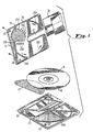
- Figure 1 which as indicated above is substantially a duplicate of Figure 6 of U.S. Patent No. 4,769,733, the same reference numerals will be used herein to describe Figure 1 as those used in the cited patent to describe Figure 6 of that patent. Also, the description of Figure 1 will generally parallel the description of Figure 6 of the cited patent. Additional reference numerals and descriptions, however, will be used in describing Figure 1 and only that description of Figure 1 which is required to establish the environment of the present invention will be set forth in reference to Figure 1. A more detailed description of the various elements of Figure 1 together with the structural and functional interrelationship of the various parts depicted in Figure 1 and their interrelationship to the transducers and disk drive with which the cartridge is utilized can be had with reference to U.S. Patent 4,769,733, which is hereby incorporated herein by reference.
- Figure 1 shows the inside surface of cartridge cover or top portion 111; the inside surface of cartridge bottom portion 112; inter-disk wiper 113 sandwiched by disk pair 10 and 14; and shutter 28.
- disks 10 and 14 are contained within the chamber or enclosure formed by the joining of generally planar cartridge bottom portion 112 and generally planar cartridge top portion 111, and shutter 28 is slidably mounted on the cartridge.
- Bottom disk wiper 114 is heat staked to the cartridge bottom portion 112 at heat stake points 114A. When in assembled form, the lower surface of disk 10 contacts bottom disk wiper 114.
- any foreign materials on the underside of disk 10 are wiped away as the disk 10 contacts bottom disk wiper 114.
- Inter-disk wiper 113 is sandwiched between disk 14 and disk 10 and serves to remove contaminates from between the disk pair as the disks rotate.
- Hold down nodes 116 in cartridge top 111 engage hold down nodes 117 in cartridge bottom 112 and hold inter-disk wiper 113 within the cartridge and between the disks.
- Top wiper 115 is adhesively joined to Bernoulli surface 35 and wipes the upper surface of disk 14 as it rotates.
- Apertures 23 and 33 are provided in the cartridge and it is in region of these apertures that transduction of data takes place in a manner as is well known to those skilled in the art.
- FIG. 2 and 3 a first embodiment of a cartridge in accordance with the invention is depicted.
- advantage is taken of the low pressure zone created within the cartridge when the disk pair 10, 14 is rotated.
- outside air is drawn into the cartridge and particulates are removed from this air, i.e., the air is filtered; the air already in the cartridge is not filtered.
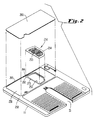
- FIG 2 is an exploded view of the opposite side of the top portion 111 of the cartridge shown in Figure 1 as modified in accordance with the first embodiment.
- a particulate removing means or filter is designated generally by the reference numeral 250.
- the filter 250 is located across opening 252 provided in cartridge top portion 111.
- the filter 250 includes a frame 254 and a filter media 255 comprised of any suitable filtering media as for example, Filtrete brand air filter media manufactured by 3M Filtration Products.
- the thickness of the filter media is approximately equal to one half the thickness of the cartridge top portion 111 in the area of the opening 252.
- the peripheral edges of the frame 254 are secured to the peripheral edges of opening 252 by any suitable means, as for example, by an adhesive.
- the peripheral edges of the opening 252 are recessed as at 253 relative to the surface 256 which, in turn, is recessed relative to the outside surface 258 of cartridge top portion 111.
- the recessed peripheral edges 253 of the opening 252 are sized to accommodate the thickness of the peripheral portions of frame 254 of filter 250.
- the filter media 255 depends from the undersurface of frame 254 and extends inwardly towards the interior of the cartridge.
- a thin cover plate 260 is sized to be received on recessed surface 256.
- Cover plate 260 may be secured to recessed surface 256 by any suitable means, as for example by an adhesive. With cover plate 260 secured in place on the recessed surface 256, the opening 252 is closed and, as best seen in Figure 3, a recessed area 262 is defined in the inside surface 35 of cartridge top portion 111.
- the filter media 255 fills the recessed area 262.
- a slot or air inlet 264 is provided in the edge 265 of outside surface 258 and an air channel 266 is provided in recessed surface 253 in order that air inlet 264 be in air flow communication with the recessed area 262 in which filter 250 is disposed.
- the recessed area 262 in which the filter 250 is positioned is in the low pressure zone created when the disk pair 10, 14 is rotated. Because the low pressure zone is comprised of a negative pressure zone relative to ambient air pressure, outside air is forced through the filter 250 by way of air inlet 264 and channel 266 and into the cartridge.
- the filtered air is generally at a lower temperature than air that has been circulating inside the cartridge. The filtered air, at lower temperature provides, an improved atmosphere for the operation of the transducer to disk interface.
- FIG. 4 a second embodiment of a cartridge is depicted.
- advantage is taken of the pressure differential or both the high and low pressure zones created within the cartridge when the disk pair 10, 14 is rotated.
- particulates are removed from the air inside the cartridge, i.e., inside air is filtered; outside air is not drawn into the cartridge through the filter.
- the filter 250 is located in opening 252 or is disposed in recessed area 262 when cover 260 is in place.
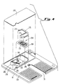
- a support member 275 Positioned on top of filter frame 254 is a support member 275 which is positioned above the filter 250 and below the cover 260.
- the legs 276, 277, and 278 provide support under the thin cover plate 260 to prevent buckling of the cover plate over the filter 250 and an air channel to be described hereinafter. Since outside air is not drawn into the cartridge in this second embodiment of the invention, the slot or air inlet 264 of Figure 2 is omitted.
- Shown at 280 is an elongated inlet. Inlet 280 is comprised of an opening 282 in the top portion 111.
- the opening 282 With cover plate 260 in position on the outside surface 256 the opening 282 is closed, i.e., the opening 282 terminates at the cover plate 260, however, the inlet 280 communicates with an air flow channel 284 defined by the cover plate 260 and an elongated recessed area 286 provided in the recessed surface 256 of cartridge top portion 111.
- the air flow channel 284 passes under the wiper 115 and has an outlet 288 which is in or communicates with the recessed area 262 in which the filter 250 is disposed.
- the legs 276 and 277 of support member 275 extend onto recessed surface 286 and have a thickness substantially equal to the height of the nodes 279 thereby providing support for the cover plate 260 over air channel 284.
- the filter 250 Since the filter 250 is disposed in the low pressure zone when the disk pair 10, 14 is rotated and the inlet 280 is in the high pressure zone, air circulating in the cartridge is forced into the inlet 280, under the wiper 115 or through air flow channel 284, and exits through outlet 288 into and through filter 250 and back into the interior of the cartridge. Again, the filtered air provides an improved environment for the operation of the transducer to disk interface.
- FIG. 6 and 7 a third embodiment of the cartridge is depicted.
- advantage is taken of both the high and low pressure zones created within the cartridge when the disk pair 10, 14 is rotated.
- particulates are removed from the air inside the cartridge; outside air is not drawn into the cartridge.
- the particulate removing means 294 comprises an adhesive lining the inside surface of the cover plate 260 and thus the air flow channel 284. Particulates in the air stream passing through air flow channel 284 which come in contact with the adhesive lining 294 will tend to become lodged in or adhere to the adhesive 294 and in this manner be removed from the air in the cartridge which comes in contact with the disks 10, 14.
- a suitable adhesive for use is Scotch 9571 brand laminating adhesive, manufactured by 3M Company.
- the adhesive lining 294 may extend across all or a part of the air channel 284 from the high pressure zone to the low pressure zone.
- FIG. 8 a fourth embodiment of a cartridge is depicted.
- This fourth embodiment is the most preferred embodiment of the invention and essentially combines features of the first three embodiments into a single cartridge.
- filter 250 is disposed in recessed area 262 provided in the inside surface 35 of cartridge top portion 111.
- inlet 280 is provided in top portion 111 which communicates with air flow channel 284.
- an additional leg 298 is provided on support member 275 and forms a barrier separating the outside air drawn into the enclosure via air inlet 264 and channel 266 from air passing through the air flow channel 284.
- the filter 250 extends across both the air flow channel outlet 288 and the air channel 266 of air inlet 280.
- the adhesive 294 lines the air flow channel 284 as in the third embodiment of the invention. It will be readily understood from the foregoing description of the most preferred embodiment of the invention that advantage is taken of both the high and low pressure zones created within the cartridge when disk pair 10, 14 is rotated and that particulates are removed from both the inside air as it passes through filter 250 and outside air drawn into the cartridge as it too passes through filter 250.
- the air inside the cartridge passing under wiper 115 and passing through air flow channel 284 may also have particulates entrained therein removed therefrom due to the adhesive lining 294 in air flow channel 284.
- the particulate removing means which comprises the filter 250 or adhesive 294 or the combination of the filter 250 and adhesive 294, is positioned in operative relationship to the enclosure (formed by the cartridge top portion 111 and bottom portion 112) and the high and low pressure zones, which zones are effected by the rotation of the disks 10, 14.
- the particulate removing means has been described as being disposed in at least the low pressure zone.
- the particulate removing means can be physically disposed in the high pressure zone if so desired.
- the adhesive may be disposed in the high pressure zone and extend to and into the low pressure zone.
- a fifth embodiment of a cartridge is depicted.
- advantage is taken of the pressure differential or both the high and low pressure zones created within the cartridge when the disk pair 10, 14 is rotated.
- particulates are removed from the air inside the cartridge, i.e., inside air is filtered; outside air is not drawn into the cartridge through the filter.
- the particulate removing means or filter 250 and wiper 115 are combined into a single element 250′.
- the elongated inlet 280 is provided in the top portion 111.
- the inlet 280 communicates with the air flow channel defined between the cover plate 260 and the rear of the filter 250′.
- a support member 275′ provides support for the cover plate 260 over the filter/wiper 250′. Since the inlet is provided in the high pressure zone, air circulating in the cartridge is forced into the inlet 280, along air channel and under and up through filter/wiper 250′.
- the filtered air provides an improved atmosphere for the operation of the transducer to disk interface.
- an adhesive may be applied to cover plate 260 as described in conjunction with the third embodiment of the invention depicted in Figures 6 and 7.
- the five embodiments of the invention have been shown and described as useful in a magnetic disk cartridge having two rotatable flexible magnetic disks mounted therein; however, it is to be understood that the concepts of this invention are fully applicable to any type cartridge having any type recording media therein. Furthermore, it is within the scope of the present invention to combine the functions of the filter 250 and wiper 115, as described in the fifth embodiment of the invention, in the first and fourth embodiments of the invention. It is also within the scope of the present invention to provide an air outlet, which would communicate directly to the outside of the cartridge, in the high pressure zone of the cartridge to permit or force air to exit the cartridge carrying with it any particulates contained therein.
Landscapes
- Filtering Of Dispersed Particles In Gases (AREA)
- Feeding And Guiding Record Carriers (AREA)
Abstract
Description
- This invention relates to disk cartridges. More particularly, this invention relates to disk cartridges of the type having rotatable recording media means mounted therein and to particulate removing means for removing particulates from air which flows in proximity to the recording media means.
- The present invention will be described in detail in association with magnetic disk cartridges of the type having rotatable flexible magnetic disk means mounted therein. It is to be understood, however, that the invention is not limited to any particular recording media, size of recording media or format and that the invention is also applicable to non-flexible or rigid recording media as well as to optical recording media of various sizes and formats.
- In United States Patent No. 4,769,733, assigned to the same assignee as the subject application, there is disclosed a magnetic data storage cartridge wherein two magnetic disks or a disk pair are coaxially joined and axially spaced such that during high speed rotation of the disks, a continuous air bearing exists between the functional portions of the disks. An inter-disk wiper is interposed between the disks and contacts the inner surfaces of the disks. Top and bottom wipers contact the outside surfaces of the disks. The bottom wiper is staked to the inside of the cartridge along one edge. The bottom wiper extends over a rib on the inside of the cartridge so that the wiper is biased toward the disk. The flexibility of the wiper material loads the wiper against the disk. This obviates what might otherwise be a problem of proper spacing from the inside of the cartridge to the disk. The top wiper is secured by adhesive to the inside of the cover so that it contacts the outer surface of the other disk.
- The wipers cover only a portion of the disk surface and are positioned at the back of the cartridge with respect to the location in which two substantially opposed transducers are brought into read/write relationship with the outer surfaces of the disks when the cartridge is inserted into a magnetic disk drive. This produces minimum interference with the stability of the rotating disks in the area of the transducers.
- The purpose of the wipers, as disclosed in this patent, was, among other things, to stabilize the disks in order that the two substantially opposed transducers could simultaneously access the outer surfaces of the two disks without causing substantial deformation of either disk by the transducer positioned adjacent to the opposite disk. The inter-disk wiper was also disclosed as serving to remove contaminates from between the disks as the disks were rotated and the top and bottom disk wipers were positioned to wipe the outside surfaces of the disk pair to wipe away any foreign materials on these surfaces.
- It may be explained here that the surface to which the top wiper is secured is a Bernoulli surface against which in operation the top disk is rotated at high speed. During high speed rotation, in a manner known to those skilled in the art, an air bearing is formed between the surface of the top disk and the Bernoulli surface and the air bearing stabilizes the top disk. In a manner as disclosed in this cited patent, the bottom disk is in turn stabilized by rotation in juxtaposition to the stabilized surface of the upper disk. In this manner, both disks are stabilized by a single Bernoulli surface.
- Such high speed rotation of the disks causes large volumes of air to be moved in and throughout the cartridge. In addition, air is both drawn into the cartridge and expelled from the cartridge. It will be appreciated that any particulates carried in the air drawn into the cartridge or carried in the air moving within the cartridge can have a detrimental affect on the record media, the transducers or their operation. This is especially so at the transducer disk interface where such particulates can cause excessive wear and also interfere with proper read/write operations.
- There is provided a disk cartridge of the type having a Bernoulli surface against which disk means is rotated, said cartridge comprising:
an enclosure having a generally planar top portion and a generally planar bottom portion, with the disk means rotatably mounted within a chamber formed between said top and bottom portions and with the underside of one of said top and bottom portions comprising said Bernoulli surface;
a disk wiper in contact with said Bernoulli surface and with one of the surfaces of said disk means, thereby to create a high pressure zone on one side of the disk wiper and a low pressure zone on the opposite side of said disk wiper upon rotation of the disk means;
characterised by
an air flow passage formed in said enclosure and having at least one end thereof in communication with the ambient air and/or one or both of said pressure zones;
and means positioned in and/or adjacent to said flow passage for removing particles from air flowing in said passage. - The foregoing and other features, objects and advantages of the present invention will be more fully appreciated and become more apparent from consideration of the following description of preferred embodiments of the invention, taken in conjunction with the attached drawings wherein like reference numerals refer to like parts throughout the several drawings.
-
- Figure 1 is substantially a duplicate of Figure 6 of the aforementioned U.S. Patent No. 4,769,733, namely, an exploded perspective view of the disk cartridge made according to a preferred embodiment of that invention which shows the interior surfaces of the cartridge and the disks contained within the cartridge.
- Figure 2 is an exploded view of the opposite side of the top portion of the cartridge shown in Figure 1 as modified in accordance with a first embodiment of the present invention;
- Figure 3 is a view of the opposite side of Figure 2;
- Figure 4 is an exploded view of the opposite side of the top portion of the cartridge shown in Figure 1 as modified in accordance with a second embodiment of the present invention;
- Figure 5 is a view of the opposite side of Figure 4;
- Figure 6 is an exploded view of the opposite side of the top portion of the cartridge shown in Figure 1 as modified in accordance with a third embodiment of the present invention;
- Figure 7 is a view of the opposite side of Figure 6;
- Figure 8 is an exploded view of the opposite side of the top portion of the cartridge shown in Figure 1 as modified in accordance with a fourth and most preferred embodiment of the present invention;
- Figure 9 is a view of the opposite side of Figure 8;
- Figure 10 is an exploded view of the opposite side of the top portion of the cartridge shown in Figure 1 as modified in accordance with a fifth embodiment of the present invention; and
- Figure 11 is a view of the opposite side of Figure 10.
-
- Referring now to Figure 1, which as indicated above is substantially a duplicate of Figure 6 of U.S. Patent No. 4,769,733, the same reference numerals will be used herein to describe Figure 1 as those used in the cited patent to describe Figure 6 of that patent. Also, the description of Figure 1 will generally parallel the description of Figure 6 of the cited patent. Additional reference numerals and descriptions, however, will be used in describing Figure 1 and only that description of Figure 1 which is required to establish the environment of the present invention will be set forth in reference to Figure 1. A more detailed description of the various elements of Figure 1 together with the structural and functional interrelationship of the various parts depicted in Figure 1 and their interrelationship to the transducers and disk drive with which the cartridge is utilized can be had with reference to U.S. Patent 4,769,733, which is hereby incorporated herein by reference.
- Figure 1 shows the inside surface of cartridge cover or top portion 111; the inside surface of
cartridge bottom portion 112;inter-disk wiper 113 sandwiched bydisk pair disks cartridge bottom portion 112 and generally planar cartridge top portion 111, and shutter 28 is slidably mounted on the cartridge.Bottom disk wiper 114 is heat staked to thecartridge bottom portion 112 atheat stake points 114A. When in assembled form, the lower surface ofdisk 10 contactsbottom disk wiper 114. When the cartridge is inserted into a disk drive anddisk pair disk 10 are wiped away as thedisk 10 contactsbottom disk wiper 114. Inter-diskwiper 113 is sandwiched betweendisk 14 anddisk 10 and serves to remove contaminates from between the disk pair as the disks rotate. Hold downnodes 116 in cartridge top 111 engage hold downnodes 117 incartridge bottom 112 and holdinter-disk wiper 113 within the cartridge and between the disks.Top wiper 115 is adhesively joined to Bernoullisurface 35 and wipes the upper surface ofdisk 14 as it rotates. It should be noted here that the wiping actions described are to be distinguished from the removal of particulates from air in close proximity to the disks will be described below with reference to Figures 2-11.Apertures 23 and 33 are provided in the cartridge and it is in region of these apertures that transduction of data takes place in a manner as is well known to those skilled in the art. - When the
disk pair arrows 200 on the inside surface of cartridge top portion 111. Applicants have discovered that rotation of thedisk pair 10, 14 (disk 14 in contact with the disk wiper 115) effects a high pressure zone in the region of thearrows 202, i.e., in viewing Figure 1, the high pressure zone is effected in the region along the side of thetop wiper 115 designated by thereference numeral 204 and slightly ahead of thedisk wiper 115. Along theopposite side 206 ofdisk wiper 115 and in the region of the arrows 208 a low pressure zone is effected. Actual mapping measurements of these two zones has indicated that the low pressure zone is comprised of a negative pressure zone relative to ambient air pressure. As will be explained more fully hereinafter, advantage is taken of the high and low pressure zones created on either side of thetop disk wiper 115. - Referring now to Figures 2 and 3, a first embodiment of a cartridge in accordance with the invention is depicted. In this first embodiment of the invention, advantage is taken of the low pressure zone created within the cartridge when the
disk pair - Figure 2 is an exploded view of the opposite side of the top portion 111 of the cartridge shown in Figure 1 as modified in accordance with the first embodiment. A particulate removing means or filter is designated generally by the
reference numeral 250. Thefilter 250 is located across opening 252 provided in cartridge top portion 111. Thefilter 250 includes aframe 254 and afilter media 255 comprised of any suitable filtering media as for example, Filtrete brand air filter media manufactured by 3M Filtration Products. The thickness of the filter media is approximately equal to one half the thickness of the cartridge top portion 111 in the area of theopening 252. The peripheral edges of theframe 254 are secured to the peripheral edges of opening 252 by any suitable means, as for example, by an adhesive. The peripheral edges of theopening 252 are recessed as at 253 relative to thesurface 256 which, in turn, is recessed relative to theoutside surface 258 of cartridge top portion 111. The recessedperipheral edges 253 of theopening 252 are sized to accommodate the thickness of the peripheral portions offrame 254 offilter 250. - When the
filter 250 is in place, thefilter media 255 depends from the undersurface offrame 254 and extends inwardly towards the interior of the cartridge. Athin cover plate 260 is sized to be received on recessedsurface 256.Cover plate 260 may be secured to recessedsurface 256 by any suitable means, as for example by an adhesive. Withcover plate 260 secured in place on the recessedsurface 256, theopening 252 is closed and, as best seen in Figure 3, a recessedarea 262 is defined in theinside surface 35 of cartridge top portion 111. Thefilter media 255 fills the recessedarea 262. - A slot or
air inlet 264 is provided in theedge 265 ofoutside surface 258 and anair channel 266 is provided in recessedsurface 253 in order thatair inlet 264 be in air flow communication with the recessedarea 262 in which filter 250 is disposed. - The recessed
area 262 in which thefilter 250 is positioned is in the low pressure zone created when thedisk pair filter 250 by way ofair inlet 264 andchannel 266 and into the cartridge. The filtered air is generally at a lower temperature than air that has been circulating inside the cartridge. The filtered air, at lower temperature provides, an improved atmosphere for the operation of the transducer to disk interface. - Referring now to Figures 4 and 5, a second embodiment of a cartridge is depicted. In this second embodiment of the invention, advantage is taken of the pressure differential or both the high and low pressure zones created within the cartridge when the
disk pair - As in the first embodiment of the invention, the
filter 250 is located in opening 252 or is disposed in recessedarea 262 whencover 260 is in place. Positioned on top offilter frame 254 is asupport member 275 which is positioned above thefilter 250 and below thecover 260. Thelegs thin cover plate 260 to prevent buckling of the cover plate over thefilter 250 and an air channel to be described hereinafter. Since outside air is not drawn into the cartridge in this second embodiment of the invention, the slot orair inlet 264 of Figure 2 is omitted. Shown at 280 is an elongated inlet.Inlet 280 is comprised of anopening 282 in the top portion 111. Withcover plate 260 in position on theoutside surface 256 theopening 282 is closed, i.e., theopening 282 terminates at thecover plate 260, however, theinlet 280 communicates with anair flow channel 284 defined by thecover plate 260 and an elongated recessedarea 286 provided in the recessedsurface 256 of cartridge top portion 111. Theair flow channel 284 passes under thewiper 115 and has anoutlet 288 which is in or communicates with the recessedarea 262 in which thefilter 250 is disposed. Thelegs support member 275 extend onto recessedsurface 286 and have a thickness substantially equal to the height of thenodes 279 thereby providing support for thecover plate 260 overair channel 284. Since thefilter 250 is disposed in the low pressure zone when thedisk pair inlet 280 is in the high pressure zone, air circulating in the cartridge is forced into theinlet 280, under thewiper 115 or throughair flow channel 284, and exits throughoutlet 288 into and throughfilter 250 and back into the interior of the cartridge. Again, the filtered air provides an improved environment for the operation of the transducer to disk interface. - Referring now to Figures 6 and 7, a third embodiment of the cartridge is depicted. In this third embodiment of the invention, advantage is taken of both the high and low pressure zones created within the cartridge when the
disk pair - Shown at 294 in Figure 6 is the particulate removing means that is utilized in this third embodiment of the cartridge. The particulate removing means 294 comprises an adhesive lining the inside surface of the
cover plate 260 and thus theair flow channel 284. Particulates in the air stream passing throughair flow channel 284 which come in contact with theadhesive lining 294 will tend to become lodged in or adhere to the adhesive 294 and in this manner be removed from the air in the cartridge which comes in contact with thedisks adhesive lining 294 may extend across all or a part of theair channel 284 from the high pressure zone to the low pressure zone. - Referring now to Figures 8 and 9, a fourth embodiment of a cartridge is depicted. This fourth embodiment is the most preferred embodiment of the invention and essentially combines features of the first three embodiments into a single cartridge. As in the first embodiment, with
cover plate 260 in position,filter 250 is disposed in recessedarea 262 provided in theinside surface 35 of cartridge top portion 111. As in the second embodiment,inlet 280 is provided in top portion 111 which communicates withair flow channel 284. In this fourth embodiment, anadditional leg 298 is provided onsupport member 275 and forms a barrier separating the outside air drawn into the enclosure viaair inlet 264 andchannel 266 from air passing through theair flow channel 284. Thefilter 250 extends across both the airflow channel outlet 288 and theair channel 266 ofair inlet 280. The adhesive 294 lines theair flow channel 284 as in the third embodiment of the invention. It will be readily understood from the foregoing description of the most preferred embodiment of the invention that advantage is taken of both the high and low pressure zones created within the cartridge whendisk pair filter 250 and outside air drawn into the cartridge as it too passes throughfilter 250. In addition, the air inside the cartridge passing underwiper 115 and passing throughair flow channel 284 may also have particulates entrained therein removed therefrom due to theadhesive lining 294 inair flow channel 284. - In each of the four embodiments of the invention thus far described and in the remaining embodiment to be described, the particulate removing means, which comprises the
filter 250 or adhesive 294 or the combination of thefilter 250 and adhesive 294, is positioned in operative relationship to the enclosure (formed by the cartridge top portion 111 and bottom portion 112) and the high and low pressure zones, which zones are effected by the rotation of thedisks - Referring now to Figures 10 and 11, a fifth embodiment of a cartridge is depicted. In this fifth embodiment of the invention, advantage is taken of the pressure differential or both the high and low pressure zones created within the cartridge when the
disk pair - In this fifth embodiment of the invention, the particulate removing means or filter 250 and
wiper 115 are combined into asingle element 250′. As in the second embodiment of the invention, theelongated inlet 280 is provided in the top portion 111. Theinlet 280 communicates with the air flow channel defined between thecover plate 260 and the rear of thefilter 250′. Asupport member 275′ provides support for thecover plate 260 over the filter/wiper 250′. Since the inlet is provided in the high pressure zone, air circulating in the cartridge is forced into theinlet 280, along air channel and under and up through filter/wiper 250′. The filtered air provides an improved atmosphere for the operation of the transducer to disk interface. If desired, an adhesive may be applied to coverplate 260 as described in conjunction with the third embodiment of the invention depicted in Figures 6 and 7. - The five embodiments of the invention have been shown and described as useful in a magnetic disk cartridge having two rotatable flexible magnetic disks mounted therein; however, it is to be understood that the concepts of this invention are fully applicable to any type cartridge having any type recording media therein. Furthermore, it is within the scope of the present invention to combine the functions of the
filter 250 andwiper 115, as described in the fifth embodiment of the invention, in the first and fourth embodiments of the invention. It is also within the scope of the present invention to provide an air outlet, which would communicate directly to the outside of the cartridge, in the high pressure zone of the cartridge to permit or force air to exit the cartridge carrying with it any particulates contained therein.
Claims (13)
- A disk cartridge of the type having a Bernoulli surface (35) against which disk means (10, 14) is rotated, said cartridge comprising:
an enclosure having a generally planar top portion (111) and a generally planar bottom portion (112), with the disk means (10, 14) rotatably mounted within a chamber formed between said top and bottom portions and with the underside of one of said top and bottom portions comprising said Bernoulli surface (35);
a disk wiper (115) in contact with said Bernoulli surface (35) and with one of the surfaces of said disk means, thereby to create a high pressure zone (202) on one side of the disk wiper and a low pressure zone (208) on the opposite side of said disk wiper upon rotation of the disk means (10, 14);
characterised by
an air flow passage (264, 266, 252; 280, 284, 252; 262, 282; 280) formed in said enclosure and having at least one end thereof in communication with the ambient air and/or one or both of said pressure zones (202, 208);
and means (255, 294, 250′) positioned in and/or adjacent to said flow passage for removing particles from air flowing in said passage. - A cartridge as claimed in claim 1, characterised in that said enclosure includes an air inlet (264) for permitting outside air to be drawn into said enclosure through said particle-removing means (255).
- A cartridge as claimed in claim 2, characterised in that said air inlet (264) of said enclosure communicates with an outlet (252) into said low pressure zone (208) and wherein said particle-removing means (255) comprises a filter disposed across said outlet (252).
- A cartridge as claimed in claim 3, characterised in that said particle-removing means (255) extends across both an air flow passage for ambient air and said air outlet (252) and said enclosure further includes a barrier means (298), said barrier means separating the ambient air drawn into said enclosure from air drawn from said zones.
- A cartridge as claimed in any preceding claim, characterised in that said air flow passage includes adhesive means (294) lining said air flow passage.
- A cartridge as claimed in any preceding claim, characterised in that said particle-removing means comprises a surface having an adhesive coating (294) thereon, and said adhesive coating serves to capture particulate material passing through said passage.
- A cartridge as claimed in any preceding claim, characterised in that said particle-removing means comprises a filter (255) positioned so that air passing through said passage passes through said filter.
- A cartridge as claimed in claim 7, characterised in that said filter (255) comprises "Filtrete" brand air filter media.
- A cartridge as claimed in any preceding claim, characterised in that said passage has one end in communication with said high pressure zone (202) and another end in communication with said low pressure zone (208).
- A cartridge as claimed in any preceding claim, characterised in that said passage is formed in the exterior surface of said cartridge.
- A cartridge as claimed in claim 10, further characterised by a cover (260) for sealing said passage from air outside said chamber.
- A cartridge as claimed in any preceding claim, which includes an air outlet from the high pressure zone (202) to the air outside the enclosure.
- A cartridge as claimed in any preceding claim, which further comprises:
a wiper (115), said wiper being secured within said enclosure and in contact with said disk means (10, 14), said high pressure zone (202) being located on one side of said wiper and said low pressure zone (203) being located on the opposite side of said wiper.
Applications Claiming Priority (3)
| Application Number | Priority Date | Filing Date | Title |
|---|---|---|---|
| US07/300,784 US4969061A (en) | 1989-01-23 | 1989-01-23 | Particulate removing means for cartridges |
| PCT/US1989/005309 WO1990008384A1 (en) | 1989-01-23 | 1989-11-22 | Particulate removing means for cartridges |
| US300784 | 1994-09-01 |
Publications (3)
| Publication Number | Publication Date |
|---|---|
| EP0454689A1 EP0454689A1 (en) | 1991-11-06 |
| EP0454689A4 EP0454689A4 (en) | 1992-07-29 |
| EP0454689B1 true EP0454689B1 (en) | 1995-02-15 |
Family
ID=23160567
Family Applications (1)
| Application Number | Title | Priority Date | Filing Date |
|---|---|---|---|
| EP90900668A Expired - Lifetime EP0454689B1 (en) | 1989-01-23 | 1989-11-22 | Particulate removing means for cartridges |
Country Status (4)
| Country | Link |
|---|---|
| US (1) | US4969061A (en) |
| EP (1) | EP0454689B1 (en) |
| DE (1) | DE68921223T2 (en) |
| WO (1) | WO1990008384A1 (en) |
Families Citing this family (12)
| Publication number | Priority date | Publication date | Assignee | Title |
|---|---|---|---|---|
| US5077726A (en) * | 1989-04-05 | 1991-12-31 | Bernoulli Optical Systems Company | Optical disc cartridge with a flexible storage medium |
| US5025336A (en) * | 1989-11-06 | 1991-06-18 | Prairietek Corporation | Disk drive apparatus |
| US5546257A (en) * | 1994-08-24 | 1996-08-13 | Jennings; Gordon | Protection and cleaning device for a disk drive |
| US6243350B1 (en) * | 1996-05-01 | 2001-06-05 | Terastor Corporation | Optical storage systems with flying optical heads for near-field recording and reading |
| US5898552A (en) * | 1996-08-02 | 1999-04-27 | Sony Corporation | Magnetic disk cartridge having strip liners |
| WO1998054717A1 (en) * | 1997-05-29 | 1998-12-03 | Digital Papyrus Corporation | A method and apparatus for dust proofing a removable data storage cartridge and drive |
| US6188545B1 (en) | 1998-11-09 | 2001-02-13 | Castlewood Systems, Inc. | Moveable disk wiper apparatus and method |
| US6459544B1 (en) | 1998-11-20 | 2002-10-01 | Bruce M. Harper | Removable cartridge for data-storage medium |
| US6466406B1 (en) | 2000-03-17 | 2002-10-15 | Iomega Corporation | Data-storage cartridge having one or more surface recesses for improved internal air circulation |
| US20040076085A1 (en) * | 2002-10-21 | 2004-04-22 | Patterson Scott R. | Data library with robotically retrievable filter cartridge |
| US7092202B1 (en) | 2002-11-15 | 2006-08-15 | Iomega Corporation | Enhanced airflow conditioning system for removable data storage cartridge |
| US20070056444A1 (en) * | 2005-07-12 | 2007-03-15 | Garikipati Vijay K | Electronic Enclosure Filter Containing Fluted Media |
Family Cites Families (5)
| Publication number | Priority date | Publication date | Assignee | Title |
|---|---|---|---|---|
| US4658318A (en) * | 1981-04-22 | 1987-04-14 | Iomega Corporation | Magnetic disk cartridge having improved locking mechanism and ringing pad |
| US4400748A (en) * | 1981-04-22 | 1983-08-23 | Iomega Corporation | Flexible magnetic disk drive using a rigid cartridge |
| US4768124A (en) * | 1982-11-09 | 1988-08-30 | Iomega Corporation | Record disk cartridge with flexible pad |
| US4769733A (en) * | 1982-11-09 | 1988-09-06 | Iomega Corporation | Wipers for pair of stabilized magnetic disks |
| US4743989A (en) * | 1986-04-21 | 1988-05-10 | Iomega Corporation | Plural magnetic disk assembly |
-
1989
- 1989-01-23 US US07/300,784 patent/US4969061A/en not_active Expired - Lifetime
- 1989-11-22 EP EP90900668A patent/EP0454689B1/en not_active Expired - Lifetime
- 1989-11-22 WO PCT/US1989/005309 patent/WO1990008384A1/en not_active Ceased
- 1989-11-22 DE DE68921223T patent/DE68921223T2/en not_active Expired - Fee Related
Also Published As
| Publication number | Publication date |
|---|---|
| EP0454689A1 (en) | 1991-11-06 |
| DE68921223T2 (en) | 1995-06-14 |
| US4969061A (en) | 1990-11-06 |
| EP0454689A4 (en) | 1992-07-29 |
| WO1990008384A1 (en) | 1990-07-26 |
| DE68921223D1 (en) | 1995-03-23 |
Similar Documents
| Publication | Publication Date | Title |
|---|---|---|
| US4969061A (en) | Particulate removing means for cartridges | |
| US6507452B1 (en) | Filtering apparatus for hard disk drive | |
| JP2607577B2 (en) | Wiper for a pair of stabilized magnetic disks | |
| US20010017744A1 (en) | Filtering apparatus for hard disk drive | |
| EP0556383B1 (en) | Head wiper for bernoulli disk drive | |
| HK1008108B (en) | Head wiper for bernoulli disk drive | |
| EP0391563A2 (en) | Optical disc cartridge with a flexible storage medium | |
| US20030231424A1 (en) | Breather filter at down-stream of re-circulation filter | |
| US7382572B1 (en) | Disk drive with flexible, integrated breather/recirculation filter elements | |
| US5521776A (en) | Magnetic disk drive with dust cleaning function | |
| US4739433A (en) | Method of cleaning magnetic recording disk of magnetic recording disk cartridge | |
| GB2225895A (en) | Magnetic disc apparatus | |
| KR100539258B1 (en) | Optical disc drive having dust removing apparatus | |
| JPS61196494A (en) | magnetic disk device | |
| WO2000055855A1 (en) | Magnetic disk cartridge | |
| JP4051828B2 (en) | Disk drive device | |
| JPS63257988A (en) | Air filter device of magnetic disk device | |
| JPH0447835Y2 (en) | ||
| JPH10144036A (en) | Disk cartridge | |
| JP2508646Y2 (en) | Optical disc drive device | |
| JP2000200470A (en) | Disc cartridge | |
| JPH11328905A (en) | Disk cartridge | |
| US8313546B2 (en) | Fluid flow filter | |
| JPH02302978A (en) | disc cartridge | |
| JPH01162285A (en) | Cartridge for floppy disk |
Legal Events
| Date | Code | Title | Description |
|---|---|---|---|
| PUAI | Public reference made under article 153(3) epc to a published international application that has entered the european phase |
Free format text: ORIGINAL CODE: 0009012 |
|
| 17P | Request for examination filed |
Effective date: 19910619 |
|
| AK | Designated contracting states |
Kind code of ref document: A1 Designated state(s): BE DE FR GB IT LU NL |
|
| A4 | Supplementary search report drawn up and despatched |
Effective date: 19920609 |
|
| AK | Designated contracting states |
Kind code of ref document: A4 Designated state(s): BE DE FR GB IT LU NL |
|
| ITF | It: translation for a ep patent filed | ||
| 17Q | First examination report despatched |
Effective date: 19930713 |
|
| GRAA | (expected) grant |
Free format text: ORIGINAL CODE: 0009210 |
|
| AK | Designated contracting states |
Kind code of ref document: B1 Designated state(s): BE DE FR GB IT LU NL |
|
| PG25 | Lapsed in a contracting state [announced via postgrant information from national office to epo] |
Ref country code: NL Effective date: 19950215 Ref country code: BE Effective date: 19950215 |
|
| REF | Corresponds to: |
Ref document number: 68921223 Country of ref document: DE Date of ref document: 19950323 |
|
| ET | Fr: translation filed | ||
| NLV1 | Nl: lapsed or annulled due to failure to fulfill the requirements of art. 29p and 29m of the patents act | ||
| PG25 | Lapsed in a contracting state [announced via postgrant information from national office to epo] |
Ref country code: LU Free format text: LAPSE BECAUSE OF NON-PAYMENT OF DUE FEES Effective date: 19951130 |
|
| PLBE | No opposition filed within time limit |
Free format text: ORIGINAL CODE: 0009261 |
|
| STAA | Information on the status of an ep patent application or granted ep patent |
Free format text: STATUS: NO OPPOSITION FILED WITHIN TIME LIMIT |
|
| 26N | No opposition filed | ||
| PGFP | Annual fee paid to national office [announced via postgrant information from national office to epo] |
Ref country code: FR Payment date: 19981110 Year of fee payment: 10 |
|
| PGFP | Annual fee paid to national office [announced via postgrant information from national office to epo] |
Ref country code: GB Payment date: 19981127 Year of fee payment: 10 |
|
| PGFP | Annual fee paid to national office [announced via postgrant information from national office to epo] |
Ref country code: DE Payment date: 19981130 Year of fee payment: 10 |
|
| PG25 | Lapsed in a contracting state [announced via postgrant information from national office to epo] |
Ref country code: GB Free format text: LAPSE BECAUSE OF NON-PAYMENT OF DUE FEES Effective date: 19991122 |
|
| GBPC | Gb: european patent ceased through non-payment of renewal fee |
Effective date: 19991122 |
|
| PG25 | Lapsed in a contracting state [announced via postgrant information from national office to epo] |
Ref country code: FR Free format text: LAPSE BECAUSE OF NON-PAYMENT OF DUE FEES Effective date: 20000731 |
|
| PG25 | Lapsed in a contracting state [announced via postgrant information from national office to epo] |
Ref country code: DE Free format text: LAPSE BECAUSE OF NON-PAYMENT OF DUE FEES Effective date: 20000901 |
|
| REG | Reference to a national code |
Ref country code: FR Ref legal event code: ST |
|
| PG25 | Lapsed in a contracting state [announced via postgrant information from national office to epo] |
Ref country code: IT Free format text: LAPSE BECAUSE OF NON-PAYMENT OF DUE FEES;WARNING: LAPSES OF ITALIAN PATENTS WITH EFFECTIVE DATE BEFORE 2007 MAY HAVE OCCURRED AT ANY TIME BEFORE 2007. THE CORRECT EFFECTIVE DATE MAY BE DIFFERENT FROM THE ONE RECORDED. Effective date: 20051122 |