EP0453592A1 - Manufacture of silicon carbide articles - Google Patents
Manufacture of silicon carbide articles Download PDFInfo
- Publication number
- EP0453592A1 EP0453592A1 EP90107736A EP90107736A EP0453592A1 EP 0453592 A1 EP0453592 A1 EP 0453592A1 EP 90107736 A EP90107736 A EP 90107736A EP 90107736 A EP90107736 A EP 90107736A EP 0453592 A1 EP0453592 A1 EP 0453592A1
- Authority
- EP
- European Patent Office
- Prior art keywords
- silicon carbide
- porous
- sprue
- silicon
- carbon
- Prior art date
- Legal status (The legal status is an assumption and is not a legal conclusion. Google has not performed a legal analysis and makes no representation as to the accuracy of the status listed.)
- Granted
Links
- HBMJWWWQQXIZIP-UHFFFAOYSA-N silicon carbide Chemical compound [Si+]#[C-] HBMJWWWQQXIZIP-UHFFFAOYSA-N 0.000 title claims abstract description 29
- 229910010271 silicon carbide Inorganic materials 0.000 title claims abstract description 26
- 238000004519 manufacturing process Methods 0.000 title claims abstract description 8
- OKTJSMMVPCPJKN-UHFFFAOYSA-N Carbon Chemical compound [C] OKTJSMMVPCPJKN-UHFFFAOYSA-N 0.000 claims abstract description 23
- 229910052799 carbon Inorganic materials 0.000 claims abstract description 21
- 229910052710 silicon Inorganic materials 0.000 claims abstract description 21
- 239000010703 silicon Substances 0.000 claims abstract description 21
- 239000000203 mixture Substances 0.000 claims abstract description 14
- 239000002245 particle Substances 0.000 claims abstract description 14
- 239000011230 binding agent Substances 0.000 claims abstract description 13
- 238000000034 method Methods 0.000 claims abstract description 12
- 239000000463 material Substances 0.000 claims abstract description 10
- 238000001746 injection moulding Methods 0.000 claims abstract description 8
- 230000009969 flowable effect Effects 0.000 claims abstract description 4
- 238000010438 heat treatment Methods 0.000 claims abstract description 4
- 229910021426 porous silicon Inorganic materials 0.000 claims abstract description 4
- 238000007789 sealing Methods 0.000 claims description 8
- XUIMIQQOPSSXEZ-UHFFFAOYSA-N Silicon Chemical compound [Si] XUIMIQQOPSSXEZ-UHFFFAOYSA-N 0.000 abstract description 17
- 208000015943 Coeliac disease Diseases 0.000 description 18
- 238000000465 moulding Methods 0.000 description 4
- 229910002804 graphite Inorganic materials 0.000 description 2
- 239000010439 graphite Substances 0.000 description 2
- 229920001169 thermoplastic Polymers 0.000 description 2
- 239000004416 thermosoftening plastic Substances 0.000 description 2
- 239000006229 carbon black Substances 0.000 description 1
- 238000006243 chemical reaction Methods 0.000 description 1
- 238000010586 diagram Methods 0.000 description 1
- 239000008187 granular material Substances 0.000 description 1
- 238000003780 insertion Methods 0.000 description 1
- 230000037431 insertion Effects 0.000 description 1
- 239000012774 insulation material Substances 0.000 description 1
- 239000013067 intermediate product Substances 0.000 description 1
- 239000007788 liquid Substances 0.000 description 1
- 238000002844 melting Methods 0.000 description 1
- 230000008018 melting Effects 0.000 description 1
- 229910052753 mercury Inorganic materials 0.000 description 1
- 239000002184 metal Substances 0.000 description 1
- 239000011148 porous material Substances 0.000 description 1
- 239000000047 product Substances 0.000 description 1
- 238000000197 pyrolysis Methods 0.000 description 1
- 230000035939 shock Effects 0.000 description 1
- 239000012899 standard injection Substances 0.000 description 1
- 239000000126 substance Substances 0.000 description 1
- 239000002699 waste material Substances 0.000 description 1
Images


Classifications
-
- C—CHEMISTRY; METALLURGY
- C04—CEMENTS; CONCRETE; ARTIFICIAL STONE; CERAMICS; REFRACTORIES
- C04B—LIME, MAGNESIA; SLAG; CEMENTS; COMPOSITIONS THEREOF, e.g. MORTARS, CONCRETE OR LIKE BUILDING MATERIALS; ARTIFICIAL STONE; CERAMICS; REFRACTORIES; TREATMENT OF NATURAL STONE
- C04B35/00—Shaped ceramic products characterised by their composition; Ceramics compositions; Processing powders of inorganic compounds preparatory to the manufacturing of ceramic products
- C04B35/515—Shaped ceramic products characterised by their composition; Ceramics compositions; Processing powders of inorganic compounds preparatory to the manufacturing of ceramic products based on non-oxide ceramics
- C04B35/56—Shaped ceramic products characterised by their composition; Ceramics compositions; Processing powders of inorganic compounds preparatory to the manufacturing of ceramic products based on non-oxide ceramics based on carbides or oxycarbides
- C04B35/565—Shaped ceramic products characterised by their composition; Ceramics compositions; Processing powders of inorganic compounds preparatory to the manufacturing of ceramic products based on non-oxide ceramics based on carbides or oxycarbides based on silicon carbide
- C04B35/573—Shaped ceramic products characterised by their composition; Ceramics compositions; Processing powders of inorganic compounds preparatory to the manufacturing of ceramic products based on non-oxide ceramics based on carbides or oxycarbides based on silicon carbide obtained by reaction sintering or recrystallisation
Definitions
- This invention relates to the manufacture of silicon carbide articles, and in particular to manufacture by injection moulding followed by siliconisation.
- Articles resistant to thermal shock and with good mechanical properties can be made from particles of the highly refractory substance silicon carbide by a variety of methods.
- a mixture flowable under heat and pressure which comprises a major proportion of silicon carbide particles and a minor proportion of organic binder material is injected through a narrow orifice to fill a shaped cavity in a mould at lower temperature.
- the article thus formed is then removed from the mould, and the sprue (ie the waste piece corresponding to the passage in the mould tool between the moulding orifice and the mould cavity) is machined off.
- the moulded article is then heated to remove the organic binder material from it and leave a porous silicon carbide body containing elemental carbon which (at this stage) weakly binds together the highly refractory silicon carbides particles.
- the elemental carbon may be present as a result of generation by pyrolysis of the original organic binder material in the mixture submitted to moulding (as in GB-1,454,622) or as a result of its inclusion per se in that mixture.
- the porous body thus produced is then impregnated with molten silicon to convert the carbon present to silicon carbide.
- the carbon present dissolves in and reacts with the molten silicon which is drawn up into the pores of the body, and the silicon carbide thus formed bonds together the original silicon carbide particles into a unitary structure of great strength.
- This step is conventionally carried out in a furnace at high temperature, eg 1500-1600 o C, and low pressure, eg 0.5mm Hg, as mentioned in the UK Patent No 1,454,622.
- the present invention is concerned with improving the method just described so as to avoid excessive contact between the surface of the weakly bonded porous shaped body obtained as intermediate product and the molten silicon employed for siliconisation, and thus reduce the possibility of damage to that body.
- elemental carbon for example in the form of finely divided graphite or carbon black, is included in the mixture in step (i) above.
- Step (iii) is carried out under the usual conditions, eg in a furnace under very low pressure.
- the sprue is used as a wick to pick up molten silicon from a block of porous carbon.
- the sprue may be inserted in a suitable sized hole in the block of porous carbon, which is supplied with molten silicon, for example either by locating the block in direct contact with molten silicon in a reservoir, or by using the block itself as a reservoir.
- the porous carbon block may conveniently be a block of porous carbon insulation material, which we have found to function effectively as a medium for mounting components by means of their sprues during siliconisation and for transferring molten silicon into the sprues, which rest in holes in the block and are arranged to be a snug fit to facilitate transfer of silicon from block to sprue.
- the siliconised sprue that results from operation of the method is of course very strong, and can if desired be left as it is. It may, however, be cut down flush with the surface of the article, or only partly, so as to leave a stub, of maximum length no more than a few mm, say up to 5-10mm, to serve as a location or alignment means, as explained later in this specification.
- the invention has particular application to the manufacture of sealing rings, but may be used for the manufacture of other, more complex, components, for example turbocharger rotors.
- the ring-shaped injection-moulded silicon carbide article 1 has an interior shoulder 2 and an exterior shoulder 3, and has the sprue 4 formed during injection moulding still integral with it.
- the article 1 can be made as follows.
- a mixture of conventional composition (suitably 61% by weight silicon carbide, particle size below 20 ⁇ m; 18% by weight graphite, particle agglomerate size below 20 ⁇ m; remainder a thermoplastic binder material) is prepared and granulated, and the granules are injection-moulded in a standard injection moulding machine, to form rings of height 6.5mm, external diameter 72.4mm and internal diameter 61mm, with a sprue length of about 40mm.
- the ring is removed from the mould and, to avoid distortion, is supported while it cools to room temperature.
- the article is then heated, while still under support, in an air oven. Once the temperature has reached a value at which the binder is soft, the rate of increase is limited to 2 o C per hour until a temperature of about 300 o C is attained. This heating first oxidises, and then pyrolyses, the thermoplastic binder while leaving the original elemental carbon in the resulting porous structure as a weak binder for the original silicon carbide particles.
- the density of the porous body formed is about 2.2g/cm3.
- the sprue can be severed by grinding. If this is done so as to leave a stub, say about 3mm high, protruding above the surface of ring 1 (the upper surface in Fig.2), the stub can serve as a location or alignment means for the ring in a metal or other housing of which it is to form a sealing component.
- FIG. 4 A further alignment means derived from a sprue is illustrated in Figures 4 and 5, Figure 5 being a cross-sectional view of the sealing ring of Figure 4.
- the sealing ring 12 shown in Figures 4 and 5 has two internal shoulders 15, 16 and the two external shoulders 17, 18 and has been produced as described above with a moulding sprue 13 (shown in dotted lines) having been used for siliconisation. However, the moulding sprue in this embodiment has been ground down to form an anti-rotation lug 14 on the sealing ring, extending between the two external shoulders 17 and 18.
Landscapes
- Chemical & Material Sciences (AREA)
- Engineering & Computer Science (AREA)
- Ceramic Engineering (AREA)
- Chemical Kinetics & Catalysis (AREA)
- Manufacturing & Machinery (AREA)
- Materials Engineering (AREA)
- Structural Engineering (AREA)
- Organic Chemistry (AREA)
- Ceramic Products (AREA)
Abstract
- (i) injection-moulding a mixture which comprises a major proportion of silicon carbide particles and a minor proportion of organic binder material, the mixture being flowable under heat and pressure,
- (ii) heating the moulded article thus formed so as to remove the organic binder material from it and obtain a porous silicon carbide body containing elemental carbon, and
- (iii)impregnating the porous body with molten silicon to convert said carbon to silicon carbide which binds together the original silicon carbide particles,
in which step (iii) is carried out by utilising as a conduit for said molten silicon the sprue that is formed integrally with the injection-moulded article in step (i).
Description
- This invention relates to the manufacture of silicon carbide articles, and in particular to manufacture by injection moulding followed by siliconisation.
- Articles resistant to thermal shock and with good mechanical properties can be made from particles of the highly refractory substance silicon carbide by a variety of methods. In the injection-moulding/siliconisation method, a mixture flowable under heat and pressure which comprises a major proportion of silicon carbide particles and a minor proportion of organic binder material is injected through a narrow orifice to fill a shaped cavity in a mould at lower temperature. The article thus formed is then removed from the mould, and the sprue (ie the waste piece corresponding to the passage in the mould tool between the moulding orifice and the mould cavity) is machined off.
- The moulded article is then heated to remove the organic binder material from it and leave a porous silicon carbide body containing elemental carbon which (at this stage) weakly binds together the highly refractory silicon carbides particles. The elemental carbon may be present as a result of generation by pyrolysis of the original organic binder material in the mixture submitted to moulding (as in GB-1,454,622) or as a result of its inclusion per se in that mixture.
- The porous body thus produced is then impregnated with molten silicon to convert the carbon present to silicon carbide. In more detail, the carbon present dissolves in and reacts with the molten silicon which is drawn up into the pores of the body, and the silicon carbide thus formed bonds together the original silicon carbide particles into a unitary structure of great strength. This step is conventionally carried out in a furnace at high temperature, eg 1500-1600oC, and low pressure, eg 0.5mm Hg, as mentioned in the UK Patent No 1,454,622.
- The present invention is concerned with improving the method just described so as to avoid excessive contact between the surface of the weakly bonded porous shaped body obtained as intermediate product and the molten silicon employed for siliconisation, and thus reduce the possibility of damage to that body.
- According to the invention there is provided a method for making a siliconised silicon carbide article by
- (i) injection-moulding a mixture which comprises a major proportion of silicon carbide particles and a minor proportion of organic binder material, the mixture being flowable under heat and pressure,
- (ii) heating the moulded article thus formed so as to remove the organic binder material from it and obtain a porous silicon carbide body containing elemental carbon, and
- (iii) impregnating the porous body with molten silicon to convert said carbon to silicon carbide which binds together the original silicon carbide particles,
- Preferably elemental carbon, for example in the form of finely divided graphite or carbon black, is included in the mixture in step (i) above.
- Step (iii) is carried out under the usual conditions, eg in a furnace under very low pressure. Preferably in step (iii) the sprue is used as a wick to pick up molten silicon from a block of porous carbon. The sprue may be inserted in a suitable sized hole in the block of porous carbon, which is supplied with molten silicon, for example either by locating the block in direct contact with molten silicon in a reservoir, or by using the block itself as a reservoir.
- The porous carbon block may conveniently be a block of porous carbon insulation material, which we have found to function effectively as a medium for mounting components by means of their sprues during siliconisation and for transferring molten silicon into the sprues, which rest in holes in the block and are arranged to be a snug fit to facilitate transfer of silicon from block to sprue.
- The siliconised sprue that results from operation of the method is of course very strong, and can if desired be left as it is. It may, however, be cut down flush with the surface of the article, or only partly, so as to leave a stub, of maximum length no more than a few mm, say up to 5-10mm, to serve as a location or alignment means, as explained later in this specification.
- The invention has particular application to the manufacture of sealing rings, but may be used for the manufacture of other, more complex, components, for example turbocharger rotors.
- The invention will now be further described with reference to the accompanying drawings, in which:
- Fig. 1 is a plan of an injection-moulded silicon carbide article, with the sprue still present, shaped as a sealing ring;
- Fig. 2 is a section on line AA in Fig. 1;
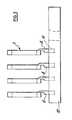
- Fig. 3 is a diagram showing an assembly of four of the articles of Fig. 1 which have been made porous and are mounted vertically for siliconisation.
- Figure 4 is a plan view of a sealing ring with an anti-rotation lug; and
- Figure 5 is a section on line BB in Figure 4.
- In Figs 1 and 2 the ring-shaped injection-moulded
silicon carbide article 1 has aninterior shoulder 2 and anexterior shoulder 3, and has thesprue 4 formed during injection moulding still integral with it. Thearticle 1 can be made as follows. - A mixture of conventional composition (suitably 61% by weight silicon carbide, particle size below 20 µm; 18% by weight graphite, particle agglomerate size below 20 µm; remainder a thermoplastic binder material) is prepared and granulated, and the granules are injection-moulded in a standard injection moulding machine, to form rings of height 6.5mm, external diameter 72.4mm and internal diameter 61mm, with a sprue length of about 40mm.
- The ring is removed from the mould and, to avoid distortion, is supported while it cools to room temperature. The article is then heated, while still under support, in an air oven. Once the temperature has reached a value at which the binder is soft, the rate of increase is limited to 2oC per hour until a temperature of about 300oC is attained. This heating first oxidises, and then pyrolyses, the thermoplastic binder while leaving the original elemental carbon in the resulting porous structure as a weak binder for the original silicon carbide particles. The density of the porous body formed is about 2.2g/cm³.
- After the porous ring has cooled, half the length of the sprue is sawn off so as to shorten the travel path of molten silicon subsequently, and the ring is supported vertically with several others by insertion (see Fig.3) of the
sprue 4 inrecess 11 in ablock 10 of porous carbon situated on the surface of a reservoir (not shown) of silicon flakes in a conventional furnace. Operation of the furnace at high temperature and very low pressure in an entirely conventional manner leads to melting of the silicon flakes and transport of liquid silicon from the reservoir into theporous block 10, and through the conduit formed byporous sprue 4 of the porous ring into the ring itself. There it reacts with the elemental carbon present to form silicon carbide, which 'reaction bonds' the particles of silicon carbide originally included in the mix subjected to injection moulding. The density of the finished product is about 3.1 g/cm³. - The sprue can be severed by grinding. If this is done so as to leave a stub, say about 3mm high, protruding above the surface of ring 1 (the upper surface in Fig.2), the stub can serve as a location or alignment means for the ring in a metal or other housing of which it is to form a sealing component.
- A further alignment means derived from a sprue is illustrated in Figures 4 and 5, Figure 5 being a cross-sectional view of the sealing ring of Figure 4.
- The
sealing ring 12 shown in Figures 4 and 5 has twointernal shoulders 15, 16 and the two external shoulders 17, 18 and has been produced as described above with a moulding sprue 13 (shown in dotted lines) having been used for siliconisation. However, the moulding sprue in this embodiment has been ground down to form ananti-rotation lug 14 on the sealing ring, extending between the two external shoulders 17 and 18.
in which step (iii) is carried out by utilising as a conduit for said molten silicon the sprue that is formed integrally with the injection-moulded article in step (i).
Claims (6)
- A method of making a siliconised silicon carbide article by(i) injection-moulding a mixture which comprises a major proportion of silicon carbide particles and a minor proportion of organic binder material, the mixture being flowable under heat and pressure,(ii) heating the moulded article thus formed so as to remove the organic binder material from it and obtain a porous silicon carbide body containing elemental carbon, and(iii)impregnating the porous body with molten silicon to convert said carbon to silicon carbide which binds together the original silicon carbide particles,characterised in that method step (iii) is carried out by utilising as a conduit for said molten silicon the sprue (4,13) that is formed integrally with the injection- moulded article in step (i).
- A method according to claim 1 characterised in that the mixture used in step (i) also comprises elemental carbon.
- A method according to claim 1 or 2 characterised in that in step (iii) the sprue is used as a wick to pick up molten silicon from a block of porous carbon.
- A method according to claim 3 characterised in that the sprue is inserted in a suitably sized hole in the block of porous carbon, which is supplied with molten silicon.
- A method according to any preceding claim characterised in that the siliconised sprue that results is cut down so as to leave a stub, of maximum length no more than a few mm, protruding from the article.
- A method according to any preceding claim characterised by being applied to the manufacture of a sealing ring.
Priority Applications (3)
| Application Number | Priority Date | Filing Date | Title |
|---|---|---|---|
| EP90107736A EP0453592B1 (en) | 1990-04-24 | 1990-04-24 | Manufacture of silicon carbide articles |
| DE90107736T DE69003091T2 (en) | 1990-04-24 | 1990-04-24 | Manufacture of silicon carbide articles. |
| US07/514,208 US5037588A (en) | 1990-04-24 | 1990-04-25 | Manufacture of silicon carbide articles |
Applications Claiming Priority (1)
| Application Number | Priority Date | Filing Date | Title |
|---|---|---|---|
| EP90107736A EP0453592B1 (en) | 1990-04-24 | 1990-04-24 | Manufacture of silicon carbide articles |
Publications (2)
| Publication Number | Publication Date |
|---|---|
| EP0453592A1 true EP0453592A1 (en) | 1991-10-30 |
| EP0453592B1 EP0453592B1 (en) | 1993-09-01 |
Family
ID=8203904
Family Applications (1)
| Application Number | Title | Priority Date | Filing Date |
|---|---|---|---|
| EP90107736A Expired - Lifetime EP0453592B1 (en) | 1990-04-24 | 1990-04-24 | Manufacture of silicon carbide articles |
Country Status (3)
| Country | Link |
|---|---|
| US (1) | US5037588A (en) |
| EP (1) | EP0453592B1 (en) |
| DE (1) | DE69003091T2 (en) |
Cited By (3)
| Publication number | Priority date | Publication date | Assignee | Title |
|---|---|---|---|---|
| WO1993020989A1 (en) * | 1990-12-13 | 1993-10-28 | T&N Technology Limited | Brake pistons and their manufacture |
| EP1829843A3 (en) * | 2006-03-01 | 2008-07-02 | Audi Ag | Method for silicating carbonaceous materials |
| US8889058B2 (en) * | 2007-09-19 | 2014-11-18 | Audi Ag | Method and device for siliconization of carbon-containing materials |
Families Citing this family (2)
| Publication number | Priority date | Publication date | Assignee | Title |
|---|---|---|---|---|
| US6221478B1 (en) | 1997-07-24 | 2001-04-24 | James Kammeyer | Surface converted graphite components and methods of making same |
| US6187197B1 (en) * | 1998-10-28 | 2001-02-13 | Marvin Haddock | Multi-stage engine coolant recycling process |
Citations (3)
| Publication number | Priority date | Publication date | Assignee | Title |
|---|---|---|---|---|
| FR2161698A5 (en) * | 1971-11-19 | 1973-07-06 | Rolls Royce | |
| DE2439930A1 (en) * | 1973-08-20 | 1975-03-20 | Ford Werke Ag | METHOD OF MANUFACTURING A SILICON CARBIDE ARTICLE |
| US4294788A (en) * | 1979-12-05 | 1981-10-13 | General Electric Company | Method of making a shaped silicon carbide-silicon matrix composite and articles made thereby |
Family Cites Families (2)
| Publication number | Priority date | Publication date | Assignee | Title |
|---|---|---|---|---|
| US4044110A (en) * | 1975-10-03 | 1977-08-23 | Ford Motor Company | Method of forming a silicon carbide article - III |
| US4446085A (en) * | 1982-08-30 | 1984-05-01 | Earsley Melvin L | Molding of seal rings |
-
1990
- 1990-04-24 DE DE90107736T patent/DE69003091T2/en not_active Expired - Fee Related
- 1990-04-24 EP EP90107736A patent/EP0453592B1/en not_active Expired - Lifetime
- 1990-04-25 US US07/514,208 patent/US5037588A/en not_active Expired - Fee Related
Patent Citations (3)
| Publication number | Priority date | Publication date | Assignee | Title |
|---|---|---|---|---|
| FR2161698A5 (en) * | 1971-11-19 | 1973-07-06 | Rolls Royce | |
| DE2439930A1 (en) * | 1973-08-20 | 1975-03-20 | Ford Werke Ag | METHOD OF MANUFACTURING A SILICON CARBIDE ARTICLE |
| US4294788A (en) * | 1979-12-05 | 1981-10-13 | General Electric Company | Method of making a shaped silicon carbide-silicon matrix composite and articles made thereby |
Cited By (5)
| Publication number | Priority date | Publication date | Assignee | Title |
|---|---|---|---|---|
| WO1993020989A1 (en) * | 1990-12-13 | 1993-10-28 | T&N Technology Limited | Brake pistons and their manufacture |
| EP1829843A3 (en) * | 2006-03-01 | 2008-07-02 | Audi Ag | Method for silicating carbonaceous materials |
| US7763224B2 (en) | 2006-03-01 | 2010-07-27 | Audi Ag | Method for siliconizing carbon-containing materials |
| US9663406B2 (en) | 2006-03-01 | 2017-05-30 | Audi Ag | Method for siliconizing carbon-containing materials |
| US8889058B2 (en) * | 2007-09-19 | 2014-11-18 | Audi Ag | Method and device for siliconization of carbon-containing materials |
Also Published As
| Publication number | Publication date |
|---|---|
| DE69003091D1 (en) | 1993-10-07 |
| EP0453592B1 (en) | 1993-09-01 |
| DE69003091T2 (en) | 1994-04-14 |
| US5037588A (en) | 1991-08-06 |
Similar Documents
| Publication | Publication Date | Title |
|---|---|---|
| US4737328A (en) | Infiltration of material with silicon | |
| US4431449A (en) | Infiltrated molded articles of spherical non-refractory metal powders | |
| EP0805729B1 (en) | Method of constructing fully dense metal molds and parts | |
| US5205970A (en) | Method of infiltration forming a silicon carbide body with improved surface finish | |
| FI84343B (en) | FOERFARANDE FOER FRAMSTAELLNING AV ETT SJAELVBAERANDE KERAMISKT KOMPOSITSTYCKE OCH ETT SAODANT KOMPOSITSTYCKE. | |
| EP0277085B1 (en) | Production of metal carbide articles | |
| US3882210A (en) | Injection of a ceramic into a mould | |
| EP0888199B1 (en) | Sleeves, their preparation, and use | |
| EP0933825A3 (en) | Separator for fuel cell and manufacturing method for the same | |
| US4491558A (en) | Austenitic manganese steel-containing composite article | |
| CN101544851A (en) | Metallic bond hollow sphere-shaped super-hard compound material and manufacturing method thereof | |
| EP0012966B1 (en) | Integral composite of polycristalline diamond and/or cubic boron nitride body phase and substrate phase and process for making it | |
| US6776955B1 (en) | Net shaped articles having complex internal undercut features | |
| EP0453592B1 (en) | Manufacture of silicon carbide articles | |
| US4320079A (en) | Method for making shaped carbon fiber structures | |
| US4793859A (en) | Infiltration of mo-containing material with silicon | |
| CA1119847A (en) | Infiltrated molded articles of spherical non-refractory metal powders | |
| GB2243601A (en) | Siliconised silicon carbide article | |
| KR870008648A (en) | Casting nozzle and manufacturing method of the nozzle | |
| KR100495289B1 (en) | Process for Preparing a Sleeve Having Exothermic Properties and/or Insulating Properties, Sleeve Prepared Thereby, Process for Preparing a Casting by Using Said Sleeve, a Casting Prepared Thereby | |
| JPH0412605B2 (en) | ||
| GB2096928A (en) | Method of casting grey iron | |
| GB2202542A (en) | Core molding composition | |
| JP4177491B2 (en) | Lighthouse | |
| JPH08253833A (en) | Copper-molybdenum alloy and its production |
Legal Events
| Date | Code | Title | Description |
|---|---|---|---|
| PUAI | Public reference made under article 153(3) epc to a published international application that has entered the european phase |
Free format text: ORIGINAL CODE: 0009012 |
|
| AK | Designated contracting states |
Kind code of ref document: A1 Designated state(s): DE FR IT |
|
| 17P | Request for examination filed |
Effective date: 19920409 |
|
| 17Q | First examination report despatched |
Effective date: 19921030 |
|
| ITF | It: translation for a ep patent filed | ||
| GRAA | (expected) grant |
Free format text: ORIGINAL CODE: 0009210 |
|
| AK | Designated contracting states |
Kind code of ref document: B1 Designated state(s): DE FR IT |
|
| REF | Corresponds to: |
Ref document number: 69003091 Country of ref document: DE Date of ref document: 19931007 |
|
| ET | Fr: translation filed | ||
| PLBE | No opposition filed within time limit |
Free format text: ORIGINAL CODE: 0009261 |
|
| STAA | Information on the status of an ep patent application or granted ep patent |
Free format text: STATUS: NO OPPOSITION FILED WITHIN TIME LIMIT |
|
| 26N | No opposition filed | ||
| PGFP | Annual fee paid to national office [announced via postgrant information from national office to epo] |
Ref country code: FR Payment date: 19950309 Year of fee payment: 6 |
|
| PGFP | Annual fee paid to national office [announced via postgrant information from national office to epo] |
Ref country code: DE Payment date: 19950322 Year of fee payment: 6 |
|
| PG25 | Lapsed in a contracting state [announced via postgrant information from national office to epo] |
Ref country code: FR Effective date: 19961227 |
|
| PG25 | Lapsed in a contracting state [announced via postgrant information from national office to epo] |
Ref country code: DE Effective date: 19970101 |
|
| REG | Reference to a national code |
Ref country code: FR Ref legal event code: ST |
|
| PG25 | Lapsed in a contracting state [announced via postgrant information from national office to epo] |
Ref country code: IT Free format text: LAPSE BECAUSE OF NON-PAYMENT OF DUE FEES;WARNING: LAPSES OF ITALIAN PATENTS WITH EFFECTIVE DATE BEFORE 2007 MAY HAVE OCCURRED AT ANY TIME BEFORE 2007. THE CORRECT EFFECTIVE DATE MAY BE DIFFERENT FROM THE ONE RECORDED. Effective date: 20050424 |