EP0453251B1 - Ultrasonic imaging of biopsy needle - Google Patents
Ultrasonic imaging of biopsy needle Download PDFInfo
- Publication number
- EP0453251B1 EP0453251B1 EP91303404A EP91303404A EP0453251B1 EP 0453251 B1 EP0453251 B1 EP 0453251B1 EP 91303404 A EP91303404 A EP 91303404A EP 91303404 A EP91303404 A EP 91303404A EP 0453251 B1 EP0453251 B1 EP 0453251B1
- Authority
- EP
- European Patent Office
- Prior art keywords
- doppler
- biopsy needle
- imaging system
- tip
- cannula
- Prior art date
- Legal status (The legal status is an assumption and is not a legal conclusion. Google has not performed a legal analysis and makes no representation as to the accuracy of the status listed.)
- Expired - Lifetime
Links
Images

Classifications
-
- A—HUMAN NECESSITIES
- A61—MEDICAL OR VETERINARY SCIENCE; HYGIENE
- A61B—DIAGNOSIS; SURGERY; IDENTIFICATION
- A61B8/00—Diagnosis using ultrasonic, sonic or infrasonic waves
- A61B8/08—Detecting organic movements or changes, e.g. tumours, cysts, swellings
- A61B8/0833—Detecting organic movements or changes, e.g. tumours, cysts, swellings involving detecting or locating foreign bodies or organic structures
- A61B8/0841—Detecting organic movements or changes, e.g. tumours, cysts, swellings involving detecting or locating foreign bodies or organic structures for locating instruments
-
- A—HUMAN NECESSITIES
- A61—MEDICAL OR VETERINARY SCIENCE; HYGIENE
- A61B—DIAGNOSIS; SURGERY; IDENTIFICATION
- A61B17/00—Surgical instruments, devices or methods, e.g. tourniquets
- A61B17/34—Trocars; Puncturing needles
- A61B17/3403—Needle locating or guiding means
-
- A—HUMAN NECESSITIES
- A61—MEDICAL OR VETERINARY SCIENCE; HYGIENE
- A61B—DIAGNOSIS; SURGERY; IDENTIFICATION
- A61B8/00—Diagnosis using ultrasonic, sonic or infrasonic waves
- A61B8/08—Detecting organic movements or changes, e.g. tumours, cysts, swellings
- A61B8/0833—Detecting organic movements or changes, e.g. tumours, cysts, swellings involving detecting or locating foreign bodies or organic structures
-
- A—HUMAN NECESSITIES
- A61—MEDICAL OR VETERINARY SCIENCE; HYGIENE
- A61B—DIAGNOSIS; SURGERY; IDENTIFICATION
- A61B17/00—Surgical instruments, devices or methods, e.g. tourniquets
- A61B17/22—Implements for squeezing-off ulcers or the like on the inside of inner organs of the body; Implements for scraping-out cavities of body organs, e.g. bones; Calculus removers; Calculus smashing apparatus; Apparatus for removing obstructions in blood vessels, not otherwise provided for
- A61B2017/22072—Implements for squeezing-off ulcers or the like on the inside of inner organs of the body; Implements for scraping-out cavities of body organs, e.g. bones; Calculus removers; Calculus smashing apparatus; Apparatus for removing obstructions in blood vessels, not otherwise provided for with an instrument channel, e.g. for replacing one instrument by the other
- A61B2017/22074—Implements for squeezing-off ulcers or the like on the inside of inner organs of the body; Implements for scraping-out cavities of body organs, e.g. bones; Calculus removers; Calculus smashing apparatus; Apparatus for removing obstructions in blood vessels, not otherwise provided for with an instrument channel, e.g. for replacing one instrument by the other the instrument being only slidable in a channel, e.g. advancing optical fibre through a channel
- A61B2017/22075—Implements for squeezing-off ulcers or the like on the inside of inner organs of the body; Implements for scraping-out cavities of body organs, e.g. bones; Calculus removers; Calculus smashing apparatus; Apparatus for removing obstructions in blood vessels, not otherwise provided for with an instrument channel, e.g. for replacing one instrument by the other the instrument being only slidable in a channel, e.g. advancing optical fibre through a channel with motorized advancing or retracting means
-
- A—HUMAN NECESSITIES
- A61—MEDICAL OR VETERINARY SCIENCE; HYGIENE
- A61B—DIAGNOSIS; SURGERY; IDENTIFICATION
- A61B17/00—Surgical instruments, devices or methods, e.g. tourniquets
- A61B17/34—Trocars; Puncturing needles
- A61B17/3403—Needle locating or guiding means
- A61B2017/3413—Needle locating or guiding means guided by ultrasound
-
- A—HUMAN NECESSITIES
- A61—MEDICAL OR VETERINARY SCIENCE; HYGIENE
- A61B—DIAGNOSIS; SURGERY; IDENTIFICATION
- A61B90/00—Instruments, implements or accessories specially adapted for surgery or diagnosis and not covered by any of the groups A61B1/00 - A61B50/00, e.g. for luxation treatment or for protecting wound edges
- A61B90/39—Markers, e.g. radio-opaque or breast lesions markers
- A61B2090/3925—Markers, e.g. radio-opaque or breast lesions markers ultrasonic
- A61B2090/3929—Active markers
Definitions
- This invention relates to ultrasonic imaging systems and, in particular, to the imaging of biopsy needles by ultrasonic imaging systems during surgical biopsy procedures.
- Surgical biopsy procedures are commonly performed with the assistance of ultrasonic imaging to enable the physician to view the tissue being biopsied. It is of course desirable during such procedures to be able to clearly visualize the needle and monitor its progression through the body as it approaches the tissue mass from which a sample is to be taken.
- Accessories to assist the physician in such procedures are readily available such as biopsy needle guides to be used in conjunction with a transducer scanhead.
- a conventional needle guide attaches to the scanhead to direct the needle to the sector or area of view of the scanhead, thereby mandating that insertion of the needle will follow a path that is confined to the area of the body being imaged.
- Other techniques to more clearly distinguish the needle in the ultrasonic image have also been suggested, such as the formation of a diffraction grating on the needle.
- the diffraction grating is designed to cause the returning ultrasonic echoes from the needle to be more intense, and hence more readily distinguishable than would otherwise be the case.
- an ultrasonic biopsy needle imaging systems as defined by claims 1 and 2.
- the present invention is advantageous as compared with the aforementioned active techniques in that no invasive transducers are employed and system integration may be minimized.
- the present invention is also advantageous as compared with the aforementioned technique of hand manipulating the needle in that the tip of the biopsy needle is preferentially and continuously visualized.
- An apparatus constructed in accordance with the principles of the present invention employs means for mechanically reciprocating a biopsy needle, and preferably a stylet carried by a biopsy needle.
- the frequency of reciprocation is a low audible frequency. Such mechanical reciprocation causes low amplitude motion at the tip of the needle, which is readily detectable by use of Doppler techniques.
- the detected mechanical motion at the needle tip is translated by Doppler detection into locational representation of the needle tip in the image of the tissue being biopsied.
- means for mechanically reciprocating a biopsy needle or stylet is connected to the needle or stylet.
- the needle or stylet motion is detected by a Doppler imaging system as the biopsy procedure is being performed.
- the cycle reciprocation of the needle or stylet is synchronized with the Doppler scanning sequence. This enables the needle tip to be displayed in a constant hue of a predetermined color for positive identification of the needle tip in an ultrasonic image of the tissue structure.
- the representation of the needle tip can obscure the structural image of the tissue which is to be biopsied. This will impair the ability of the physician to precisely locate the needle tip in proximity to the target tissue.
- the representation of the Doppler signal response of the needle tip provides a color modulation of the image of the tissue structure.
- the target tissue is at all times visible to the physician and is not obscured by the Doppler signal response of the needle tip, and the hue and intensity of the color of the target tissue provides a precise indication of the proximity of the needle tip to the target tissue.
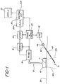
- FIGURE 1 a system for ultrasonically imaging a biopsy needle in accordance with the present invention is illustrated in block diagram form.
- An ultrasonic scanhead 10 including a plurality of imaging transducers 11 is in contact with the surface 30 of the skin of a patient.
- the scanhead 10 is a phased array scanning transducer device.
- the scanhead is connected by a cable 12 to a transmitter and receiver module 14, which provides drivers for supplying energizing pulses or waves to the transducers 11, and receivers for receiving and amplifying electrical signals produced by the transducers in response to the reception of echoes and return signals from the tissue structure being scanned.
- the transducers of the scanhead are energized in a synchronized manner to generate phased array ultrasonic waves under control of a timing and control system 24 connected to the transmitting and receiving module 14.
- the received and amplified electrical signals are demodulated to system baseband signals by a demodulator 16, then stored in a memory or store 18 in positional correspondence to the rays or vectors of interrogation of the phased array scanhead.
- the stored signals are then supplied to a processor 20, where they are filtered by a high pass filter 20a and analyzed by a spectral estimator 20b.
- the spectral estimator provides data which is analyzed for phase shift information as will be described in conjunction with FIGURE 4 below, which information is then translated to positionally representative velocity display information, such as color.
- the display information is then displayed in the desired image format on a display 22.
- the elements thus far described are those of a color flow imaging system such as that employed in the Ultramark 9 color flow imaging system available from Advanced Technology Laboratories, Inc. of Bothell
- a bioopsy needle including a hollow cannula 40 with a tapered and pointed distal tip. Carried within the cannula as it is inserted into the tissue is a removable member 42 extending to the pointed tip, such as a stylet. The proximal end of the member 42 is coupled to a mechanism 44 which longitudinally reciprocates the member or stylet.
- the mechanism 44 may be any one of a variety of devices which generate linear reciprocating motion, such as a linear motor, solenoid, speaker coil, or other device capable of developing and coupling longitudinal reciprocating motion to the member 42.
- the mechanism 44 is energized by an oscillator 46 which develops an appropriate energizing waveform for the mechanism, such as a sine wave, pulse, sawtooth or other waveform.
- an oscillator 46 which develops an appropriate energizing waveform for the mechanism, such as a sine wave, pulse, sawtooth or other waveform.
- the oscillator waveform is synchronized with the energization of the transducers 11 of the scanhead by connection of the oscillator 46 to the timing and control system 24, thereby synchronizing the motion of the member 42 with the rays of the scanhead for clear and continuous visualization of the biopsy needle.
- the method of using the biopsy needle of the present invention is as follows.
- the scanhead 10 is placed against the tissue surface 30 and maneuvered until the mass 31 to be biopsied is viewed in the image sector.
- the image sector is represented in FIGURE 1 by the dashed sector boundaries 32a and 32b on either side of the mass 31.
- the mechanism 44 is connected to member 42 of the biopsy needle and energized to longitudinally reciprocate the member 42 within the cannula 40.
- the biopsy needle is then inserted into the tissue and directed toward the mass 31 and into the field of view of the scanhead. As the needle comes into the field of view, the motion of the vibrating member at the tip of the cannula causes a Doppler response by the imaging system.
- the Doppler response is indicated positionally in the structural ultrasound image as by a color spot or dot.
- the color spot or dot indicates the position of the motion of the member 42 at the cannula tip, and as the biopsy needle is directed toward the mass 31 the color spot will approach the mass 31 in the display image.
- the color spot converges with the mass 31 in the image the cannula 40 is properly positioned to perform a biopsy of the mass.
- the member 42 is withdrawn from the cannula at that point to allow biopsy through the cannula.
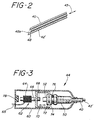
- FIGURE 2 a stylet 42' is reciprocated longitudinally within the cannula 40, as indicated by the arrow 43.
- the motion imparted to the stylet is confined in the longitudinal direction to as great a degree as possible.
- the Doppler response of the needle is substantially confined to the very tip of the needle, where the tip of the stylet is reciprocating between its retracted position as shown at 48 and its extended position as indicated by the dashed line at the cannula opening at 48a.
- the range of travel between positions 48 and 48a is only a few millimeters or less, and generally around one millimeter.
- a visual Doppler response is only the motion of the stylet at the open needle tip, to the exclusion of the body of the cannula. Since it is the needle tip that is to be maneuvered precisely to the tissue to be biopsied, it is preferable to have the needle tip highlighted in the image, which is accomplished if the only Doppler response is from the needle tip.
- Radial vibration components can cause motion of the cannula surface, which can undesirably elicit a Doppler response from various locations along the surface of the cannula 40 and hence visualization of this motion in the image in addition to that at the needle tip. This can present a confusing image to the user, who is trying to intently follow the path of the needle tip. By minimizing radial motion component and resulting Doppler responses from the cannula, the accuracy of the biopsy procedure is enhanced.
- the greatest distal extension of the range of travel of the stylet is only to the open end of the cannula, and not beyond. It is desirable to avoid any potential damage to tissue which would be caused by reciprocating the stylet tip beyond the open cannula tip.
- the only cutting of tissue should be that done by the sharpened cannula tip under the controlled manipulation of the surgeon.
- a mechanism for longitudinally moving member 42 of the biopsy needle of FIGURE 1 is shown in the cross-sectional view of FIGURE 3 of the proximal end of the biopsy needle.
- Attached to the end of the cannula 40 is a cannula hub 50, and attached to the end of the stylet 42' is a stylet hub 52.
- Located around the stylet hub 52 are two spaced annular rings or flanges 72 and 74.
- This proximal end of the biopsy needle fits inside the housing 60 of the reciprocating mechanism.
- a solenoid 62 Inside the proximal end of the housing 60 is a solenoid 62, including a coil 64 and a movable plunger 66 which is threaded at the end 68. Wires 65 from the coil 64 exit from the rear of the housing 60.
- the threaded end of the plunger 66 threads into a reciprocating slider 70, which has an opening at its distal end that engages the stylet hub 52 between the rings 72.
- a rubber O-ring 76 forward of the flange 74 and a rubber bumper 78 rearward of the plunger assist the mechanism at turn-around.
- the solenoid 62 is energized by an appropriate waveform to longitudinally reciprocate the plunger 66 within the coil 64.
- the plunger reciprocates it moves the slider 70 as indicated by the arrow, thereby longitudinally reciprocating the stylet 42' within the cannula 40.
- the O-ring 76 and bumper 78 damp the motion of the mechanism when it reverses its direction.
- a speaker coil arrangement may alternatively be employed, in which a coil is the moving component.
- the speaker coil type of mechanism may be preferred, as it is the lower coil mass which is moving as opposed to the generally larger mass of a solenoid plunger.
- the color flow imaging system described with reference to FIGURE 1 operates by transmitting a series of ultrasound pulses, called an ensemble.
- the ensemble of pulses is sent in a single direction, referred to as a ray line.
- Four such ray lines, R1, R2, R3, and R4 are illustratively shown in FIGURE 4.
- Return signals from the ensemble of pulses are received, demodulated, and stored with respect to position along the ray line, as indicated by positions S1, S2, S3, ... Sn-2, Sn-1, Sn of ray line R1 in FIGURE 4.
- the processing includes high pass filtering of the signal information followed by spectral estimation.
- An important recognition of the present invention is that, although Doppler is commonly referred to by users as having a frequency or frequencies of operation, the spectral estimation does not measure a frequency; it determines a phase shift. It is only when the phase shift is divided by time and presented to the user in this format that a frequency translation is derived.
- the principle of the present invention is that the motion at the tip of the needle has a velocity of translation or range of translation between ray lines, and it is this velocity or range of translation which causes a Doppler response by a color flow imaging system.
- the drive signal for the motive mechanism 44 is illustratively shown as a sawtooth waveform in FIGURE 5a, with turn-around of the mechanism occuring at times to, t1, t2, etc. These turnaround times are synchronized to the commencement of ensemble transmission, or to periods of conventional two-dimensional structural imaging performed between ray line Doppler interrogations.
- FIGURE 5b is drawn in correspondence with the waveform of FIGURE 5a, and illustrates the occurrence of stylet tip turn-around in synchronization with the beginning of every fourth ray line interrogation. In this example, turn-around occurs after the fourth ray line, the eighth, the twelfth, and so forth.
- the timing and control system 24 provides the ray line ensemble synchronizing pulse suitable for use by the oscillating mechanism 46.
- the biopsy needle can be reciprocated over a wide range of frequencies. Audio frequencies have been found to be preferred for their ease of application, preferably frequencies of several hundred Hertz and most preferably below one hundred Hertz. For instance, in a constructed embodiment a sequence of 52 ultrasound pulses were transmitted to interrogate a group of ray lines for Doppler information and to detect structure in a corresponding image sector area. The pulse rate used was 4 KHz. At the end of this pulse sequence the direction of travel of the stylet tip was reversed and the stylet moved in the opposite direction for the same time period. Dividing the pulse rate by the number of pulses corresponding to a full cycle of travel for the stylet, 104 pulses, gives a frequency of approximately 38.5 Hertz, the oscillating frequency for the stylet.
- the mechanism 46 of FIGURE 1 may be housed in or attached to the ultrasound machine and connected to the proximal end of the member 42 by a thin sheathed cable similar to a speedometer cable.
- the mechanism within the ultrasound machine provides the necessary motion, which is carried to the stylet by the cable in the sheath. The user is thereby presented with a very light biopsy needle arrangement connected to the ultrasound machine only by a thin sheath.
- the conventional color flow imaging system strongly emphasizes the flow characteristics in a structure by inserting areas of color into an image where flow is occurring. While highlighting flow, there is no representation of structure in such an image where flow is occurring, as the tissue structure is obscured by the color. This is undesirable in use of the present invention, where the user constantly desires to be able to view the mass which is to be biopsied as the needle tip approaches the mass. Instead of replacing and hence masking the structure of the mass with color as the needle tip approaches the mass, in a preferred embodiment the color representative of the needle tip location is used to modulate the display of the mass. Thus, as the needle tip approaches the mass, the image of the mass will turn color as the needle tip reaches the mass.
- the image of the mass is never obscured by color Doppler; instead, the image of the mass turns brightly colored as the needle tip reaches it.
- the center of the colored area is the location of the needle tip opening where the motion of the stylet tip is generating the Doppler response.
Abstract
Description
- This invention relates to ultrasonic imaging systems and, in particular, to the imaging of biopsy needles by ultrasonic imaging systems during surgical biopsy procedures.
- Surgical biopsy procedures are commonly performed with the assistance of ultrasonic imaging to enable the physician to view the tissue being biopsied. It is of course desirable during such procedures to be able to clearly visualize the needle and monitor its progression through the body as it approaches the tissue mass from which a sample is to be taken. Accessories to assist the physician in such procedures are readily available such as biopsy needle guides to be used in conjunction with a transducer scanhead. A conventional needle guide attaches to the scanhead to direct the needle to the sector or area of view of the scanhead, thereby mandating that insertion of the needle will follow a path that is confined to the area of the body being imaged. Other techniques to more clearly distinguish the needle in the ultrasonic image have also been suggested, such as the formation of a diffraction grating on the needle. The diffraction grating is designed to cause the returning ultrasonic echoes from the needle to be more intense, and hence more readily distinguishable than would otherwise be the case.
- A series of patents including U.S. Patents 3,556,079; 4,249,539; 4,431,006; 4,407,294; and 4,428,379 have suggested an active approach to ultrasonically imaging a biopsy needle. In these patents an ultrasonic transducer is attached to the biopsy needle to cause the needle to transmit and/or receive ultrasonic waves in cooperation with an imaging scanhead. In the various configurations shown in these patents the transducer is attached to the proximal (external) end of the needle and the needle becomes a conductor of ultrasound, or the transducer is physically located at the distal tip of the needle or a stylet carried within the needle. To varying degrees the techniques discussed in these patents enable the tip of the needle to be sharply visualized in the ultrasonic image by reason of the presence of the active transducer element in association with the needle, and particularly when it is located at the needle tip. These techniques have two significant drawbacks, however. One is the construction of a highly miniaturized transducer for in vivo use, and the accompanying concerns for patient safety. The second is the need for significant system integration required to synchronize signals to and from the biopsy needle transducer with the signals of the imaging scanhead. While potentially offering the advantages of high needle visibility and precision, these active and invasive techniques pose significant implementation dilemmas.
- The principles of a technique for passively visualizing a biopsy needle was recently reported in the Journal of Ultrasound in Medicine, Vol. 9, at pp 243-45 (1990). There it was noted that the passage of biopsy needles or their guide wires was distinctly evident on color Doppler images as the needle or guide wire was being moved. Hand manipulation of a biopsy needle or guide wire, it was found, provided a color image that corresponded to the shaft of the needle. Such a technique is inherent in the physical principles of Doppler imaging, and is in many cases preferable to the above active techniques by reason of its simplicity and lack of need for additional system integration. The technique suffers shortcomings in that the image of the needle is only highly defined when the needle is being manipulated, and is a coarse representation of the entire needle shaft. It would be preferable to be able to continually visualize only the tip of the needle, to better localize the proximity of the needle tip to the tissue which is to be biopsied.
- In accordance with the present invention, there are provided an ultrasonic biopsy needle imaging systems as defined by
claims - It has been found that unsynchronized reciprocation of the biopsy needle or stylet can cause a constantly changing Moire pattern when the Doppler representation of the needle tip is displayed in color. In accordance with a first aspect of a preferred embodiment of the present invention, the cycle reciprocation of the needle or stylet is synchronized with the Doppler scanning sequence. This enables the needle tip to be displayed in a constant hue of a predetermined color for positive identification of the needle tip in an ultrasonic image of the tissue structure.
- It has further been found that when the needle tip is represented by its Doppler signal response, the representation of the needle tip can obscure the structural image of the tissue which is to be biopsied. This will impair the ability of the physician to precisely locate the needle tip in proximity to the target tissue. In accordance with a further aspect of a preferred embodiment of the present invention, the representation of the Doppler signal response of the needle tip provides a color modulation of the image of the tissue structure. Thus, the target tissue is at all times visible to the physician and is not obscured by the Doppler signal response of the needle tip, and the hue and intensity of the color of the target tissue provides a precise indication of the proximity of the needle tip to the target tissue.
- In the drawings:
- FIGURE 1 illustrates in block diagram form a system for ultrasonically imaging a biopsy needle in accordance with the principles of the present invention;
- FIGURE 2 is a cross-sectional view of the distal end of a biopsy needle constructed in accordance with the principles of the present invention;
- FIGURE 3 is a cross-sectional view of a mechanism for vibrating a biopsy needle in accordance with the principles of the present invention;
- FIGURE 4 is a representation of rays of an ultraxonic sector illustrating the principles of the present invention; and
- FIGURES 5a and 5b are a waveform and timing diagram illustrating operation of a biopsy needle of the present invention.
- Referring first to FIGURE 1, a system for ultrasonically imaging a biopsy needle in accordance with the present invention is illustrated in block diagram form. An
ultrasonic scanhead 10 including a plurality of imaging transducers 11 is in contact with thesurface 30 of the skin of a patient. In the preferred embodiment thescanhead 10 is a phased array scanning transducer device. The scanhead is connected by acable 12 to a transmitter andreceiver module 14, which provides drivers for supplying energizing pulses or waves to the transducers 11, and receivers for receiving and amplifying electrical signals produced by the transducers in response to the reception of echoes and return signals from the tissue structure being scanned. The transducers of the scanhead are energized in a synchronized manner to generate phased array ultrasonic waves under control of a timing andcontrol system 24 connected to the transmitting and receivingmodule 14. The received and amplified electrical signals are demodulated to system baseband signals by ademodulator 16, then stored in a memory or store 18 in positional correspondence to the rays or vectors of interrogation of the phased array scanhead. The stored signals are then supplied to aprocessor 20, where they are filtered by a high pass filter 20a and analyzed by aspectral estimator 20b. The spectral estimator provides data which is analyzed for phase shift information as will be described in conjunction with FIGURE 4 below, which information is then translated to positionally representative velocity display information, such as color. The display information is then displayed in the desired image format on adisplay 22. The elements thus far described are those of a color flow imaging system such as that employed in the Ultramark 9 color flow imaging system available from Advanced Technology Laboratories, Inc. of Bothell, Washington. - In accordance with the principles of the present invention a bioopsy needle is provided, including a
hollow cannula 40 with a tapered and pointed distal tip. Carried within the cannula as it is inserted into the tissue is aremovable member 42 extending to the pointed tip, such as a stylet. The proximal end of themember 42 is coupled to amechanism 44 which longitudinally reciprocates the member or stylet. Themechanism 44 may be any one of a variety of devices which generate linear reciprocating motion, such as a linear motor, solenoid, speaker coil, or other device capable of developing and coupling longitudinal reciprocating motion to themember 42. Themechanism 44 is energized by anoscillator 46 which develops an appropriate energizing waveform for the mechanism, such as a sine wave, pulse, sawtooth or other waveform. As will be described below, the oscillator waveform is synchronized with the energization of the transducers 11 of the scanhead by connection of theoscillator 46 to the timing andcontrol system 24, thereby synchronizing the motion of themember 42 with the rays of the scanhead for clear and continuous visualization of the biopsy needle. - The method of using the biopsy needle of the present invention is as follows. The
scanhead 10 is placed against thetissue surface 30 and maneuvered until themass 31 to be biopsied is viewed in the image sector. The image sector is represented in FIGURE 1 by thedashed sector boundaries mass 31. Themechanism 44 is connected tomember 42 of the biopsy needle and energized to longitudinally reciprocate themember 42 within thecannula 40. The biopsy needle is then inserted into the tissue and directed toward themass 31 and into the field of view of the scanhead. As the needle comes into the field of view, the motion of the vibrating member at the tip of the cannula causes a Doppler response by the imaging system. The Doppler response is indicated positionally in the structural ultrasound image as by a color spot or dot. The color spot or dot indicates the position of the motion of themember 42 at the cannula tip, and as the biopsy needle is directed toward themass 31 the color spot will approach themass 31 in the display image. When the color spot converges with the mass 31 in the image thecannula 40 is properly positioned to perform a biopsy of the mass. Themember 42 is withdrawn from the cannula at that point to allow biopsy through the cannula. - The motion of the
member 42 of the biopsy needle is more clearly shown in the enlarged view of the distal end of the needle in FIGURE 2. In FIGURE 2 a stylet 42' is reciprocated longitudinally within thecannula 40, as indicated by the arrow 43. Preferably the motion imparted to the stylet is confined in the longitudinal direction to as great a degree as possible. When radial vibration components are minimized, the Doppler response of the needle is substantially confined to the very tip of the needle, where the tip of the stylet is reciprocating between its retracted position as shown at 48 and its extended position as indicated by the dashed line at the cannula opening at 48a. In a constructed embodiment, the range of travel betweenpositions 48 and 48a is only a few millimeters or less, and generally around one millimeter. Thus, what will appear in the ultrasonic image as a visual Doppler response is only the motion of the stylet at the open needle tip, to the exclusion of the body of the cannula. Since it is the needle tip that is to be maneuvered precisely to the tissue to be biopsied, it is preferable to have the needle tip highlighted in the image, which is accomplished if the only Doppler response is from the needle tip. Radial vibration components can cause motion of the cannula surface, which can undesirably elicit a Doppler response from various locations along the surface of thecannula 40 and hence visualization of this motion in the image in addition to that at the needle tip. This can present a confusing image to the user, who is trying to intently follow the path of the needle tip. By minimizing radial motion component and resulting Doppler responses from the cannula, the accuracy of the biopsy procedure is enhanced. - Moreover, by minimizing radial motion components in the needle, sensations of vibration are not transmitted into the tissue or the hand of the user. While radial vibration components will unavoidably occur when the needle is bent as it is inserted, a common practice, as the needle is straightened the sensation of vibration at the cannula surface is reduced.
- In a preferred embodiment of the present invention, the greatest distal extension of the range of travel of the stylet is only to the open end of the cannula, and not beyond. It is desirable to avoid any potential damage to tissue which would be caused by reciprocating the stylet tip beyond the open cannula tip. The only cutting of tissue should be that done by the sharpened cannula tip under the controlled manipulation of the surgeon.
- A mechanism for longitudinally moving
member 42 of the biopsy needle of FIGURE 1 is shown in the cross-sectional view of FIGURE 3 of the proximal end of the biopsy needle. Attached to the end of thecannula 40 is acannula hub 50, and attached to the end of the stylet 42' is astylet hub 52. Located around thestylet hub 52 are two spaced annular rings orflanges housing 60 of the reciprocating mechanism. Inside the proximal end of thehousing 60 is asolenoid 62, including acoil 64 and amovable plunger 66 which is threaded at theend 68.Wires 65 from thecoil 64 exit from the rear of thehousing 60. The threaded end of theplunger 66 threads into a reciprocatingslider 70, which has an opening at its distal end that engages thestylet hub 52 between therings 72. A rubber O-ring 76 forward of theflange 74 and arubber bumper 78 rearward of the plunger assist the mechanism at turn-around. - In operation, the
solenoid 62 is energized by an appropriate waveform to longitudinally reciprocate theplunger 66 within thecoil 64. As the plunger reciprocates it moves theslider 70 as indicated by the arrow, thereby longitudinally reciprocating the stylet 42' within thecannula 40. The O-ring 76 andbumper 78 damp the motion of the mechanism when it reverses its direction. - Other mechanisms such as a linear motor may alternatively be employed to generate the desired reciprocating motion in place of the solenoid. A speaker coil arrangement may alternatively be employed, in which a coil is the moving component. In certain applications the speaker coil type of mechanism may be preferred, as it is the lower coil mass which is moving as opposed to the generally larger mass of a solenoid plunger.
- The use of the biopsy needle arrangement of the present invention with the preferred color flow imaging display system is explained with reference to FIGURES 4, 5a, and 5b. The color flow imaging system described with reference to FIGURE 1 operates by transmitting a series of ultrasound pulses, called an ensemble. The ensemble of pulses is sent in a single direction, referred to as a ray line. Four such ray lines, R1, R2, R3, and R4, are illustratively shown in FIGURE 4. Return signals from the ensemble of pulses are received, demodulated, and stored with respect to position along the ray line, as indicated by positions S1, S2, S3, ... Sn-2, Sn-1, Sn of ray line R1 in FIGURE 4. As the signals from ray line R1 are being processed a similar ensemble is transmitted and received for the next ray line R2. The processing includes high pass filtering of the signal information followed by spectral estimation. An important recognition of the present invention is that, although Doppler is commonly referred to by users as having a frequency or frequencies of operation, the spectral estimation does not measure a frequency; it determines a phase shift. It is only when the phase shift is divided by time and presented to the user in this format that a frequency translation is derived. The principle of the present invention is that the motion at the tip of the needle has a velocity of translation or range of translation between ray lines, and it is this velocity or range of translation which causes a Doppler response by a color flow imaging system. Contrary to what common belief would dictate, it is not the frequency of vibration of the needle which is being measured, but rather the Doppler shifted signals resulting from translation of the needle tip. In practice, a number of ray line ensembles are transmitted, received and processed, such as those of ray lines R1, R2, R3, and R4 of FIGURE 4. Signal response across the ray lines, as indicated by the arrows extending from S1, S2, S3, etc. are then analyzed for Doppler shift indicative of motion, and motion is then displayed positionally with color and intensity representative of direction and velocity of motion.
- It has been found that when the stylet tip is moved asynchronously with respect to the color flow imaging system operation, a moving or flickering Moire pattern will develop in the color spot representative of the motion at the needle tip. The color will flicker or change as motion changes with respect to the ray line timing from one direction to another. If the ray line interrogation is done at the precise instant when the stylet tip is reversing direction, there is effectively no motion and hence no visualization of the needle tip in the ultrasonic image. These problems are resolved by synchronizing the motion of the biopsy needle with the timing of the ray line Doppler interrogation. The drive signal for the
motive mechanism 44 is illustratively shown as a sawtooth waveform in FIGURE 5a, with turn-around of the mechanism occuring at times to, t1, t2, etc. These turnaround times are synchronized to the commencement of ensemble transmission, or to periods of conventional two-dimensional structural imaging performed between ray line Doppler interrogations. FIGURE 5b is drawn in correspondence with the waveform of FIGURE 5a, and illustrates the occurrence of stylet tip turn-around in synchronization with the beginning of every fourth ray line interrogation. In this example, turn-around occurs after the fourth ray line, the eighth, the twelfth, and so forth. With stylet tip motion synchronized in this manner, the deleterious Moire pattern effects and turn-around image dropouts can be remedied. In FIGURE 1, the timing andcontrol system 24 provides the ray line ensemble synchronizing pulse suitable for use by theoscillating mechanism 46. - It has been found that the biopsy needle can be reciprocated over a wide range of frequencies. Audio frequencies have been found to be preferred for their ease of application, preferably frequencies of several hundred Hertz and most preferably below one hundred Hertz. For instance, in a constructed embodiment a sequence of 52 ultrasound pulses were transmitted to interrogate a group of ray lines for Doppler information and to detect structure in a corresponding image sector area. The pulse rate used was 4 KHz. At the end of this pulse sequence the direction of travel of the stylet tip was reversed and the stylet moved in the opposite direction for the same time period. Dividing the pulse rate by the number of pulses corresponding to a full cycle of travel for the stylet, 104 pulses, gives a frequency of approximately 38.5 Hertz, the oscillating frequency for the stylet.
- It has also been found desirable in certain applications to reduce the size and weight of the mechanism at the proximal end of the end of the needle in FIGURE 3 may be undesirable for some users. In those applications the
mechanism 46 of FIGURE 1 may be housed in or attached to the ultrasound machine and connected to the proximal end of themember 42 by a thin sheathed cable similar to a speedometer cable. The mechanism within the ultrasound machine provides the necessary motion, which is carried to the stylet by the cable in the sheath. The user is thereby presented with a very light biopsy needle arrangement connected to the ultrasound machine only by a thin sheath. - It has further been found that the conventional color flow imaging system strongly emphasizes the flow characteristics in a structure by inserting areas of color into an image where flow is occurring. While highlighting flow, there is no representation of structure in such an image where flow is occurring, as the tissue structure is obscured by the color. This is undesirable in use of the present invention, where the user constantly desires to be able to view the mass which is to be biopsied as the needle tip approaches the mass. Instead of replacing and hence masking the structure of the mass with color as the needle tip approaches the mass, in a preferred embodiment the color representative of the needle tip location is used to modulate the display of the mass. Thus, as the needle tip approaches the mass, the image of the mass will turn color as the needle tip reaches the mass. The image of the mass is never obscured by color Doppler; instead, the image of the mass turns brightly colored as the needle tip reaches it. The center of the colored area is the location of the needle tip opening where the motion of the stylet tip is generating the Doppler response.
Claims (12)
- An ultrasonic biopsy needle imaging system comprising:an ultrasonic imaging system (20,22) for generating a structural image of the interior of the body in which motion is locationally represented by the transmission and reception of Doppler signals by Doppler transmission and reception means (10,14) at a Doppler pulse repetition frequency and the display of Doppler derived motion signals within said structural image;a biopsy needle including a hollow cannula (40) having a pointed distal tip;
characterised in that said imaging system further comprises:motive means (44), coupled to said biopsy needle, for continuously reciprocating the tip of the cannula (40) at a reciprocating frequency which is detectable by said Doppler transmission and reception means; andtiming and control means (24) arranged to be coupled to said Doppler transmission and reception means (10,14) for controlling the transmission of Doppler pulses at a Doppler pulse repetition frequency and for measuring the Doppler-shifted signals resulting from said reciprocation of the tip of cannula (40), said motive means (44) being energized in synchronization with said Doppler pulses to produce Doppler shifted signals detectable at said Doppler pulse repetition frequency, such that the motion of the tip of the cannula (40) is imaged within said structural image of the interior of the body at a position corresponding to the position of the tip of the cannula (40). - An ultrasonic biopsy needle imaging system comprising:an ultrasonic imaging system (20,22) for generating a structural image of the interior of the body in which motion is locationally represented by the transmission and reception of Doppler signals by Doppler transmission and reception means (10,14) at a Doppler pulse repetition frequency and the display of Doppler derived motion signals within said structural image;a biopsy needle including a hollow cannula (40) having a pointed distal tip and carrying a removable member (42) within;
characterised in that said imaging system further comprises:motive means (44), coupled to said removable member (42), for continuously reciprocating said removable member (42) carried within the cannula (40) at a reciprocating frequency which is detectable by said Doppler transmission and reception means; andtiming and control means (24) arranged to be coupled to said Doppler transmission and reception means (10,14) for controlling the transmission of Doppler pulses at a Doppler pulse repetition frequency and for measuring the Doppler-shifted signals resulting from said reciprocation of the removable member (42), said motive means (44) being energized in synchronization with said Doppler pulses to produce Doppler shifted signals detectable at said Doppler pulse repetition frequency, such that the motion of the removable member (42) is imaged within said structural image of the interior of the body at a position corresponding to the position of the removable member (42). - The ultrasonic biopsy needle imaging system of claim 2, wherein said removable member (42) is arranged to reciprocate between a first position (48a) at which the distal end of said member (42) is substantially aligned with the distal end of said cannula (40), and a second position (48) at which the distal end of said member (42) is retracted within said cannula (40) with respect to said first position (48a).
- The ultrasonic biopsy needle imaging system of claim 2, wherein said removable member (42) comprises a stylet (42').
- The ultrasonic biopsy needle imaging system of claim 1, further comprising means for coupling motion produced by said motive means (44) to said biopsy needle.
- The ultrasonic biopsy needle imaging system of claim 5, wherein said coupling means includes a sheathed cable.
- The ultrasonic biopsy needle imaging system of any preceding claim, wherein said motive means (44) is arranged to cause reciprocation at a frequency which is less than 1000 hertz.
- The ultrasonic biopsy imaging system of claim 7, wherein said motive means (44) is arranged to cause reciprocation at a frequency which is less than 100 hertz.
- The ultrasonic biopsy needle imaging system of any one of claims 1 to 8, wherein said motive means (44) includes a solenoid (62).
- The ultrasonic biopsy needle imaging system of any one of claims 1 to 8, wherein said motive means (44) includes a speaker-type moving coil.
- The ultrasonic biopsy needle imaging system of any one of claims 1 and 5 to 10, wherein said motive means (44) is arranged to cause reciprocation along substantially the longitudinal direction with respect to said biopsy needle.
- The ultrasonic biopsy needle imaging system of any one of claims 1 and 5 to 11, and arranged to generate further an image in which structure is locationally represented, and wherein said tip of said cannula (40) is locationally represented in said image by modulating said structural image with a colour in the vicinity of the location of said tip in said image.
Applications Claiming Priority (2)
| Application Number | Priority Date | Filing Date | Title |
|---|---|---|---|
| US511382 | 1990-04-18 | ||
| US07/511,382 US5095910A (en) | 1990-04-18 | 1990-04-18 | Ultrasonic imaging of biopsy needle |
Publications (2)
| Publication Number | Publication Date |
|---|---|
| EP0453251A1 EP0453251A1 (en) | 1991-10-23 |
| EP0453251B1 true EP0453251B1 (en) | 1997-08-20 |
Family
ID=24034659
Family Applications (1)
| Application Number | Title | Priority Date | Filing Date |
|---|---|---|---|
| EP91303404A Expired - Lifetime EP0453251B1 (en) | 1990-04-18 | 1991-04-17 | Ultrasonic imaging of biopsy needle |
Country Status (5)
| Country | Link |
|---|---|
| US (1) | US5095910A (en) |
| EP (1) | EP0453251B1 (en) |
| JP (1) | JP3146018B2 (en) |
| AT (1) | ATE156984T1 (en) |
| DE (1) | DE69127310T2 (en) |
Cited By (1)
| Publication number | Priority date | Publication date | Assignee | Title |
|---|---|---|---|---|
| US11369296B2 (en) | 2011-02-01 | 2022-06-28 | Olberon Medical Innovation Sas | Needle holder |
Families Citing this family (99)
| Publication number | Priority date | Publication date | Assignee | Title |
|---|---|---|---|---|
| US5230339A (en) * | 1991-06-13 | 1993-07-27 | Array Tech, Inc. | Performance evaluation of ultrasonic examination equipment |
| US5517990A (en) * | 1992-11-30 | 1996-05-21 | The Cleveland Clinic Foundation | Stereotaxy wand and tool guide |
| US5329927A (en) * | 1993-02-25 | 1994-07-19 | Echo Cath, Inc. | Apparatus and method for locating an interventional medical device with a ultrasound color imaging system |
| US5983123A (en) * | 1993-10-29 | 1999-11-09 | United States Surgical Corporation | Methods and apparatus for performing ultrasound and enhanced X-ray imaging |
| JP3461509B2 (en) * | 1993-10-29 | 2003-10-27 | ユナイテッド ステイツ サージカル コーポレイション | Apparatus for Sonomammography and better X-ray photography |
| GB2287319B (en) * | 1994-03-12 | 1998-02-25 | John Francis Cockburn | Medical apparatus for ultrasonic methods of ultrasonic imaging |
| AU703770B2 (en) * | 1994-03-12 | 1999-04-01 | Donald Cockburn | Medical needle for use in ultrasound imaging and method of enhancing the visability of such a needle to ultrasound |
| US5425370A (en) * | 1994-03-23 | 1995-06-20 | Echocath, Inc. | Method and apparatus for locating vibrating devices |
| GB2298368B (en) * | 1995-02-22 | 1999-01-20 | John Francis Cockburn | Medical needle assembly for use in ultrasound imaging |
| US5807304A (en) * | 1995-03-09 | 1998-09-15 | Cockburn; John F. | Medical needle for use in ultrasound imaging |
| US5833627A (en) * | 1995-04-13 | 1998-11-10 | United States Surgical Corporation | Image-guided biopsy apparatus and methods of use |
| KR19990029038A (en) * | 1995-07-16 | 1999-04-15 | 요아브 빨띠에리 | Free aiming of needle ceramic |
| US6231514B1 (en) | 1996-06-26 | 2001-05-15 | Tobo, Llc | Device for use in temporary insertion of a sensor within a patient's body |
| US5851180A (en) * | 1996-07-12 | 1998-12-22 | United States Surgical Corporation | Traction-inducing compression assembly for enhanced tissue imaging |
| US5820552A (en) * | 1996-07-12 | 1998-10-13 | United States Surgical Corporation | Sonography and biopsy apparatus |
| US5758650A (en) * | 1996-09-30 | 1998-06-02 | Siemens Medical Systems, Inc. | Universal needle guide for ultrasonic transducers |
| US5967991A (en) * | 1996-12-03 | 1999-10-19 | Echocath, Inc. | Drive apparatus for an interventional medical device used in an ultrasonic imaging system |
| US6053871A (en) | 1997-01-21 | 2000-04-25 | William Cook Australia Pty. Ltd | Calibrated hollow probe for use with ultrasound imaging |
| WO1998033451A1 (en) * | 1997-02-04 | 1998-08-06 | National Aeronautics And Space Administration | Multimodality instrument for tissue characterization |
| US5836882A (en) * | 1997-03-17 | 1998-11-17 | Frazin; Leon J. | Method and apparatus of localizing an insertion end of a probe within a biotic structure |
| JP3723663B2 (en) * | 1997-07-15 | 2005-12-07 | フクダ電子株式会社 | Ultrasonic diagnostic equipment |
| US6027457A (en) * | 1998-06-18 | 2000-02-22 | United States Surgical Corporation | Apparatus and method for securing tissue during ultrasound examination and biopsy |
| JP2002541947A (en) | 1999-04-15 | 2002-12-10 | ウルトラガイド・リミテッド | Apparatus and method for detecting bending of medical invasive device during medical procedure |
| US6577904B1 (en) | 2000-03-30 | 2003-06-10 | Cardiac Pacemakers, Inc. | Ultrasound echogenic cardiac lead |
| US6695786B2 (en) * | 2001-03-16 | 2004-02-24 | U-Systems, Inc. | Guide and position monitor for invasive medical instrument |
| AU2002359576A1 (en) | 2001-12-03 | 2003-06-17 | Ekos Corporation | Catheter with multiple ultrasound radiating members |
| US6875179B2 (en) * | 2002-06-17 | 2005-04-05 | Board Of Trustees Of The University Of Arkansas | Ultrasonic guided catheter deployment system |
| US6716176B1 (en) | 2002-09-30 | 2004-04-06 | Tobo, Llc | Device for use in temporary insertion of a sensor within a patient's body |
| US7010337B2 (en) * | 2002-10-24 | 2006-03-07 | Furnary Anthony P | Method and apparatus for monitoring blood condition and cardiopulmonary function |
| US7329225B2 (en) * | 2003-02-12 | 2008-02-12 | Duke University | Methods, devices, systems and computer program products for oscillating shafts using real time 3D ultrasound |
| US20040260199A1 (en) * | 2003-06-19 | 2004-12-23 | Wilson-Cook Medical, Inc. | Cytology collection device |
| US20050159676A1 (en) * | 2003-08-13 | 2005-07-21 | Taylor James D. | Targeted biopsy delivery system |
| WO2005096953A1 (en) * | 2004-03-31 | 2005-10-20 | Wilson-Cook Medical Inc. | Biopsy needle system |
| US7452357B2 (en) * | 2004-10-22 | 2008-11-18 | Ethicon Endo-Surgery, Inc. | System and method for planning treatment of tissue |
| US7833221B2 (en) * | 2004-10-22 | 2010-11-16 | Ethicon Endo-Surgery, Inc. | System and method for treatment of tissue using the tissue as a fiducial |
| US20060089626A1 (en) * | 2004-10-22 | 2006-04-27 | Vlegele James W | Surgical device guide for use with an imaging system |
| CN101076284A (en) * | 2004-12-13 | 2007-11-21 | 皇家飞利浦电子股份有限公司 | Cannula inserting system |
| US8852111B2 (en) * | 2005-09-02 | 2014-10-07 | Ultrasound Ventures, Llc | Ultrasound guidance system |
| US8118743B2 (en) * | 2006-05-26 | 2012-02-21 | Ultrasound Ventures, Llc | Sterile cover |
| US8496593B2 (en) * | 2006-05-26 | 2013-07-30 | Robert Park | Needle guide |
| US7728868B2 (en) | 2006-08-02 | 2010-06-01 | Inneroptic Technology, Inc. | System and method of providing real-time dynamic imagery of a medical procedure site using multiple modalities |
| WO2008067053A2 (en) * | 2006-10-12 | 2008-06-05 | Lawrence Group Medical Device Trust | Novel needle driver for magnetic resonance elastography |
| US10182833B2 (en) | 2007-01-08 | 2019-01-22 | Ekos Corporation | Power parameters for ultrasonic catheter |
| US9044568B2 (en) | 2007-06-22 | 2015-06-02 | Ekos Corporation | Method and apparatus for treatment of intracranial hemorrhages |
| JP2010537698A (en) * | 2007-08-28 | 2010-12-09 | コーニンクレッカ フィリップス エレクトロニクス エヌ ヴィ | Dual-pass color Doppler imaging system and method for simultaneous visualization of invasive devices and vasculature imaging |
| JP5416900B2 (en) | 2007-11-22 | 2014-02-12 | 株式会社東芝 | Ultrasonic diagnostic apparatus and puncture support control program |
| WO2009094646A2 (en) | 2008-01-24 | 2009-07-30 | The University Of North Carolina At Chapel Hill | Methods, systems, and computer readable media for image guided ablation |
| US8340379B2 (en) | 2008-03-07 | 2012-12-25 | Inneroptic Technology, Inc. | Systems and methods for displaying guidance data based on updated deformable imaging data |
| WO2009141690A1 (en) * | 2008-05-23 | 2009-11-26 | Oscillon Ltd | Method and device for recognizing tissue structure using doppler effect |
| US8473027B2 (en) * | 2008-07-03 | 2013-06-25 | Qsum Biopsy Disposables Llc | Process for draping breast MRI imaging coils |
| US9138286B2 (en) * | 2008-10-20 | 2015-09-22 | Nuvue Therapeutics, Inc. | Ultrasound detectable interventional medical device |
| US8554307B2 (en) | 2010-04-12 | 2013-10-08 | Inneroptic Technology, Inc. | Image annotation in image-guided medical procedures |
| US11464578B2 (en) | 2009-02-17 | 2022-10-11 | Inneroptic Technology, Inc. | Systems, methods, apparatuses, and computer-readable media for image management in image-guided medical procedures |
| US8690776B2 (en) | 2009-02-17 | 2014-04-08 | Inneroptic Technology, Inc. | Systems, methods, apparatuses, and computer-readable media for image guided surgery |
| US8641621B2 (en) * | 2009-02-17 | 2014-02-04 | Inneroptic Technology, Inc. | Systems, methods, apparatuses, and computer-readable media for image management in image-guided medical procedures |
| US8388550B2 (en) * | 2009-05-19 | 2013-03-05 | Cook Medical Technologies Llc | Guidable cutting instrument |
| US10039527B2 (en) * | 2009-05-20 | 2018-08-07 | Analogic Canada Corporation | Ultrasound systems incorporating spatial position sensors and associated methods |
| US9895135B2 (en) * | 2009-05-20 | 2018-02-20 | Analogic Canada Corporation | Freehand ultrasound imaging systems and methods providing position quality feedback |
| US8449466B2 (en) * | 2009-05-28 | 2013-05-28 | Edwards Lifesciences Corporation | System and method for locating medical devices in vivo using ultrasound Doppler mode |
| EP2442725B1 (en) * | 2009-06-18 | 2013-08-21 | Quanta Fluid Solutions Ltd | Vascular access monitoring device |
| EP2442851B1 (en) | 2009-06-18 | 2013-09-04 | Quanta Fluid Solutions Ltd | Vascular access monitoring device |
| US8663110B2 (en) | 2009-11-17 | 2014-03-04 | Samsung Medison Co., Ltd. | Providing an optimal ultrasound image for interventional treatment in a medical system |
| US20110124949A1 (en) * | 2009-11-25 | 2011-05-26 | Qsum Biopsy Disposables Llc | Method and apparatus for stabilizing tubing during a brachytherapy procedure |
| US9486162B2 (en) | 2010-01-08 | 2016-11-08 | Ultrasonix Medical Corporation | Spatial needle guidance system and associated methods |
| JP5980201B2 (en) * | 2010-05-28 | 2016-08-31 | シー・アール・バード・インコーポレーテッドC R Bard Incorporated | Insertion guidance system for needles and medical components |
| WO2011154782A1 (en) | 2010-06-07 | 2011-12-15 | Koninklijke Philips Electronics N.V. | Ultrasonic visualization of percutaneous needles, intravascular catheters and other invasive devices |
| EP2454996A1 (en) * | 2010-11-17 | 2012-05-23 | Samsung Medison Co., Ltd. | Providing an optimal ultrasound image for interventional treatment in a medical system |
| US20120130414A1 (en) * | 2010-11-19 | 2012-05-24 | Corlius Fourie Birkill | Vibrating needle adjustment device |
| EP2640276A1 (en) | 2010-11-19 | 2013-09-25 | Koninklijke Philips N.V. | A method for guiding the insertion of a surgical instrument with three dimensional ultrasonic imaging |
| CN102727257B (en) | 2011-03-31 | 2016-08-03 | 通用电气公司 | Puncture needle method for visualizing and device |
| ITMO20110272A1 (en) * | 2011-10-27 | 2013-04-28 | Delta Med Srl | NEEDLE-CANNULA FOR MEDICAL USE |
| CN103169493A (en) * | 2011-12-20 | 2013-06-26 | 通用电气公司 | Device and method for guiding ultraphonic probe and ultraphonic system |
| US9295449B2 (en) | 2012-01-23 | 2016-03-29 | Ultrasonix Medical Corporation | Landmarks for ultrasound imaging |
| WO2013116240A1 (en) | 2012-01-30 | 2013-08-08 | Inneroptic Technology, Inc. | Multiple medical device guidance |
| US8945113B2 (en) | 2012-04-05 | 2015-02-03 | Covidien Lp | Electrosurgical tissue ablation systems capable of detecting excessive bending of a probe and alerting a user |
| GB201301866D0 (en) | 2013-02-01 | 2013-03-20 | Olberon Ltd | Needle location device |
| US9622719B2 (en) | 2013-02-26 | 2017-04-18 | Allen Maizes | Color ultrasound needle |
| US10314559B2 (en) | 2013-03-14 | 2019-06-11 | Inneroptic Technology, Inc. | Medical device guidance |
| US20140276082A1 (en) * | 2013-03-14 | 2014-09-18 | Lumoptik Llc | Ultrasound transducer with needle channel |
| GB201304798D0 (en) * | 2013-03-15 | 2013-05-01 | Univ Dundee | Medical apparatus visualisation |
| GB201305755D0 (en) | 2013-03-28 | 2013-05-15 | Quanta Fluid Solutions Ltd | Re-Use of a Hemodialysis Cartridge |
| CN103340674A (en) * | 2013-06-27 | 2013-10-09 | 苏州边枫电子科技有限公司 | Puncture needle based on ultrasonic probe vibration detection |
| CN103879859A (en) * | 2014-04-11 | 2014-06-25 | 山东华邦建设集团有限公司 | Construction hoist |
| GB201409796D0 (en) | 2014-06-02 | 2014-07-16 | Quanta Fluid Solutions Ltd | Method of heat sanitization of a haemodialysis water circuit using a calculated dose |
| US9901406B2 (en) | 2014-10-02 | 2018-02-27 | Inneroptic Technology, Inc. | Affected region display associated with a medical device |
| US10188467B2 (en) | 2014-12-12 | 2019-01-29 | Inneroptic Technology, Inc. | Surgical guidance intersection display |
| EP3307388B1 (en) | 2015-06-10 | 2022-06-22 | Ekos Corporation | Ultrasound catheter |
| US9949700B2 (en) | 2015-07-22 | 2018-04-24 | Inneroptic Technology, Inc. | Medical device approaches |
| US11793543B2 (en) | 2015-09-18 | 2023-10-24 | Obvius Robotics, Inc. | Device and method for automated insertion of penetrating member |
| WO2017049146A1 (en) * | 2015-09-18 | 2017-03-23 | Actuated Medical, Inc. | Device and system for insertion of penetrating member |
| EP3367912B1 (en) | 2015-10-27 | 2018-12-26 | Koninklijke Philips N.V. | Medical probe for ultrasound imaging |
| GB201523104D0 (en) | 2015-12-30 | 2016-02-10 | Quanta Fluid Solutions Ltd | Dialysis machine |
| US9675319B1 (en) | 2016-02-17 | 2017-06-13 | Inneroptic Technology, Inc. | Loupe display |
| US10939905B2 (en) | 2016-08-26 | 2021-03-09 | Edwards Lifesciences Corporation | Suture clips, deployment devices therefor, and methods of use |
| US10278778B2 (en) | 2016-10-27 | 2019-05-07 | Inneroptic Technology, Inc. | Medical device navigation using a virtual 3D space |
| GB201622119D0 (en) | 2016-12-23 | 2017-02-08 | Quanta Dialysis Tech Ltd | Improved valve leak detection system |
| US11259879B2 (en) | 2017-08-01 | 2022-03-01 | Inneroptic Technology, Inc. | Selective transparency to assist medical device navigation |
| MX2020003574A (en) * | 2017-09-29 | 2020-08-03 | Bard Inc C R | Apparatus and method for tracking a medical ultrasonic object. |
| US11484365B2 (en) | 2018-01-23 | 2022-11-01 | Inneroptic Technology, Inc. | Medical image guidance |
Family Cites Families (10)
| Publication number | Priority date | Publication date | Assignee | Title |
|---|---|---|---|---|
| US3556079A (en) * | 1967-05-16 | 1971-01-19 | Haruo Omizo | Method of puncturing a medical instrument under guidance of ultrasound |
| US3570476A (en) * | 1968-11-18 | 1971-03-16 | David Paul Gregg | Magnetostrictive medical instrument |
| US3805787A (en) * | 1972-06-16 | 1974-04-23 | Surgical Design Corp | Ultrasonic surgical instrument |
| JPS5558154A (en) * | 1978-10-24 | 1980-04-30 | Toshimitsu Mushiya | Electronic diagnosis device |
| US4401124A (en) * | 1981-08-13 | 1983-08-30 | Technicare Corporation | Reflection enhancement of a biopsy needle |
| US4428379A (en) * | 1982-01-07 | 1984-01-31 | Technicare Corporation | Passive ultrasound needle probe locator |
| US4431006A (en) * | 1982-01-07 | 1984-02-14 | Technicare Corporation | Passive ultrasound needle probe locator |
| US4407294A (en) * | 1982-01-07 | 1983-10-04 | Technicare Corporation | Ultrasound tissue probe localization system |
| DE3311804C2 (en) * | 1983-03-31 | 1994-08-04 | Hans J Dr Einighammer | Method and device for the highlighted sonographic representation of needle tips |
| US4816018A (en) * | 1985-08-02 | 1989-03-28 | Ultramed Corporation | Ultrasonic probe tip |
-
1990
- 1990-04-18 US US07/511,382 patent/US5095910A/en not_active Expired - Fee Related
-
1991
- 1991-04-17 DE DE69127310T patent/DE69127310T2/en not_active Expired - Fee Related
- 1991-04-17 AT AT91303404T patent/ATE156984T1/en active
- 1991-04-17 EP EP91303404A patent/EP0453251B1/en not_active Expired - Lifetime
- 1991-04-18 JP JP08663491A patent/JP3146018B2/en not_active Expired - Fee Related
Non-Patent Citations (1)
| Title |
|---|
| "Motion marking in color Doppler ultrasound needle and catheter visualization", T. Kurohiji et al., Journal of Ultrasound in Medicine, Vol. 9, pages 243-245, 1990. * |
Cited By (1)
| Publication number | Priority date | Publication date | Assignee | Title |
|---|---|---|---|---|
| US11369296B2 (en) | 2011-02-01 | 2022-06-28 | Olberon Medical Innovation Sas | Needle holder |
Also Published As
| Publication number | Publication date |
|---|---|
| US5095910A (en) | 1992-03-17 |
| JPH04227239A (en) | 1992-08-17 |
| JP3146018B2 (en) | 2001-03-12 |
| DE69127310T2 (en) | 1998-01-22 |
| DE69127310D1 (en) | 1997-09-25 |
| ATE156984T1 (en) | 1997-09-15 |
| EP0453251A1 (en) | 1991-10-23 |
Similar Documents
| Publication | Publication Date | Title |
|---|---|---|
| EP0453251B1 (en) | Ultrasonic imaging of biopsy needle | |
| EP0755223B1 (en) | Apparatus for locating vibrating medical devices | |
| US5799655A (en) | Method and apparatus for ultrasound imaging and atherectomy | |
| CN108027437B (en) | Ultrasound system with wide depth and detailed viewing | |
| JP4443672B2 (en) | Ultrasonic diagnostic equipment | |
| EP3013245B1 (en) | Shape injection into ultrasound image to calibrate beam patterns in real-time | |
| EP0547159B1 (en) | Ultrasonic imaging system and insonifier | |
| US9155518B2 (en) | Ultrasound imaging apparatus and method for generating ultrasound image | |
| US6685644B2 (en) | Ultrasound diagnostic apparatus | |
| US20130158390A1 (en) | Ultrasonic needle guiding apparatus, method and system | |
| US20170188991A1 (en) | High quality closed-loop ultrasound imaging system | |
| US6068599A (en) | Blood vessel puncturing device using ultrasound | |
| US5549112A (en) | Medical needle for use in ultrasound imaging and method of enhancing the visibility of such a needle to ultrasound | |
| US20060184034A1 (en) | Ultrasonic probe with an integrated display, tracking and pointing devices | |
| EP3013246B1 (en) | Acoustic highlighting of interventional instruments | |
| EP2039297B1 (en) | Ultrasound diagnostic apparatus | |
| US5728124A (en) | Medical needle for use in ultrasound imaging and method of enhancing the visiblity of such a needle to ultrasound | |
| WO2015092628A1 (en) | Ultrasound imaging systems and methods for tracking locations of an invasive medical device | |
| CN101784235A (en) | Dual path color doppler imaging system and method for simultaneous invasive device visualization and vasculature imaging | |
| EP1804669B1 (en) | System for amplifying transmit waveforms generated by an ultrasonic system | |
| EP0019793A2 (en) | Method for determining the velocity of moving material, especially in the body, and device for this determination and for displaying parts of the body | |
| US20040230111A1 (en) | Methods, devices, systems and computer program products for oscillating shafts using real time 3D ultrasound | |
| JPS6090542A (en) | Sensor for ultrasonic photographing apparatus | |
| GB2367895A (en) | Needle location system for use with ultrasound imager | |
| EP3815615A1 (en) | Systems and methods for positioning ultrasound patches |
Legal Events
| Date | Code | Title | Description |
|---|---|---|---|
| PUAI | Public reference made under article 153(3) epc to a published international application that has entered the european phase |
Free format text: ORIGINAL CODE: 0009012 |
|
| AK | Designated contracting states |
Kind code of ref document: A1 Designated state(s): AT BE CH DE DK ES FR GB GR IT LI LU NL SE |
|
| 17P | Request for examination filed |
Effective date: 19920331 |
|
| 17Q | First examination report despatched |
Effective date: 19940718 |
|
| GRAG | Despatch of communication of intention to grant |
Free format text: ORIGINAL CODE: EPIDOS AGRA |
|
| GRAH | Despatch of communication of intention to grant a patent |
Free format text: ORIGINAL CODE: EPIDOS IGRA |
|
| GRAH | Despatch of communication of intention to grant a patent |
Free format text: ORIGINAL CODE: EPIDOS IGRA |
|
| GRAA | (expected) grant |
Free format text: ORIGINAL CODE: 0009210 |
|
| AK | Designated contracting states |
Kind code of ref document: B1 Designated state(s): AT BE CH DE DK ES FR GB GR IT LI LU NL SE |
|
| PG25 | Lapsed in a contracting state [announced via postgrant information from national office to epo] |
Ref country code: LI Free format text: LAPSE BECAUSE OF FAILURE TO SUBMIT A TRANSLATION OF THE DESCRIPTION OR TO PAY THE FEE WITHIN THE PRESCRIBED TIME-LIMIT Effective date: 19970820 Ref country code: GR Free format text: LAPSE BECAUSE OF FAILURE TO SUBMIT A TRANSLATION OF THE DESCRIPTION OR TO PAY THE FEE WITHIN THE PRESCRIBED TIME-LIMIT Effective date: 19970820 Ref country code: ES Free format text: THE PATENT HAS BEEN ANNULLED BY A DECISION OF A NATIONAL AUTHORITY Effective date: 19970820 Ref country code: DK Free format text: LAPSE BECAUSE OF NON-PAYMENT OF DUE FEES Effective date: 19970820 Ref country code: CH Free format text: LAPSE BECAUSE OF FAILURE TO SUBMIT A TRANSLATION OF THE DESCRIPTION OR TO PAY THE FEE WITHIN THE PRESCRIBED TIME-LIMIT Effective date: 19970820 Ref country code: BE Effective date: 19970820 Ref country code: AT Effective date: 19970820 |
|
| REF | Corresponds to: |
Ref document number: 156984 Country of ref document: AT Date of ref document: 19970915 Kind code of ref document: T |
|
| REG | Reference to a national code |
Ref country code: CH Ref legal event code: EP |
|
| REF | Corresponds to: |
Ref document number: 69127310 Country of ref document: DE Date of ref document: 19970925 |
|
| ET | Fr: translation filed | ||
| ITF | It: translation for a ep patent filed |
Owner name: STUDIO TORTA S.R.L. |
|
| PG25 | Lapsed in a contracting state [announced via postgrant information from national office to epo] |
Ref country code: SE Effective date: 19971120 |
|
| K1C1 | Correction of patent application (title page) published |
Effective date: 19911023 |
|
| REG | Reference to a national code |
Ref country code: CH Ref legal event code: PL |
|
| PG25 | Lapsed in a contracting state [announced via postgrant information from national office to epo] |
Ref country code: LU Free format text: LAPSE BECAUSE OF NON-PAYMENT OF DUE FEES Effective date: 19980417 |
|
| PLBE | No opposition filed within time limit |
Free format text: ORIGINAL CODE: 0009261 |
|
| STAA | Information on the status of an ep patent application or granted ep patent |
Free format text: STATUS: NO OPPOSITION FILED WITHIN TIME LIMIT |
|
| 26N | No opposition filed | ||
| PGFP | Annual fee paid to national office [announced via postgrant information from national office to epo] |
Ref country code: NL Payment date: 19990426 Year of fee payment: 9 |
|
| PG25 | Lapsed in a contracting state [announced via postgrant information from national office to epo] |
Ref country code: NL Free format text: LAPSE BECAUSE OF NON-PAYMENT OF DUE FEES Effective date: 20001101 |
|
| NLV4 | Nl: lapsed or anulled due to non-payment of the annual fee |
Effective date: 20001101 |
|
| REG | Reference to a national code |
Ref country code: GB Ref legal event code: IF02 |
|
| REG | Reference to a national code |
Ref country code: FR Ref legal event code: D6 |
|
| REG | Reference to a national code |
Ref country code: GB Ref legal event code: 746 Effective date: 20021025 |
|
| PGFP | Annual fee paid to national office [announced via postgrant information from national office to epo] |
Ref country code: FR Payment date: 20030424 Year of fee payment: 13 |
|
| PGFP | Annual fee paid to national office [announced via postgrant information from national office to epo] |
Ref country code: GB Payment date: 20030430 Year of fee payment: 13 |
|
| PGFP | Annual fee paid to national office [announced via postgrant information from national office to epo] |
Ref country code: DE Payment date: 20030616 Year of fee payment: 13 |
|
| PG25 | Lapsed in a contracting state [announced via postgrant information from national office to epo] |
Ref country code: GB Free format text: LAPSE BECAUSE OF NON-PAYMENT OF DUE FEES Effective date: 20040417 |
|
| PG25 | Lapsed in a contracting state [announced via postgrant information from national office to epo] |
Ref country code: DE Free format text: LAPSE BECAUSE OF NON-PAYMENT OF DUE FEES Effective date: 20041103 |
|
| GBPC | Gb: european patent ceased through non-payment of renewal fee |
Effective date: 20040417 |
|
| PG25 | Lapsed in a contracting state [announced via postgrant information from national office to epo] |
Ref country code: FR Free format text: LAPSE BECAUSE OF NON-PAYMENT OF DUE FEES Effective date: 20041231 |
|
| REG | Reference to a national code |
Ref country code: FR Ref legal event code: ST |
|
| PG25 | Lapsed in a contracting state [announced via postgrant information from national office to epo] |
Ref country code: IT Free format text: LAPSE BECAUSE OF NON-PAYMENT OF DUE FEES;WARNING: LAPSES OF ITALIAN PATENTS WITH EFFECTIVE DATE BEFORE 2007 MAY HAVE OCCURRED AT ANY TIME BEFORE 2007. THE CORRECT EFFECTIVE DATE MAY BE DIFFERENT FROM THE ONE RECORDED. Effective date: 20050417 |