EP0453200B1 - Modular hearing aid - Google Patents
Modular hearing aid Download PDFInfo
- Publication number
- EP0453200B1 EP0453200B1 EP91303281A EP91303281A EP0453200B1 EP 0453200 B1 EP0453200 B1 EP 0453200B1 EP 91303281 A EP91303281 A EP 91303281A EP 91303281 A EP91303281 A EP 91303281A EP 0453200 B1 EP0453200 B1 EP 0453200B1
- Authority
- EP
- European Patent Office
- Prior art keywords
- module
- hearing aid
- receiver
- modules
- amplifier
- Prior art date
- Legal status (The legal status is an assumption and is not a legal conclusion. Google has not performed a legal analysis and makes no representation as to the accuracy of the status listed.)
- Expired - Lifetime
Links
Images




Classifications
-
- H—ELECTRICITY
- H04—ELECTRIC COMMUNICATION TECHNIQUE
- H04R—LOUDSPEAKERS, MICROPHONES, GRAMOPHONE PICK-UPS OR LIKE ACOUSTIC ELECTROMECHANICAL TRANSDUCERS; ELECTRIC HEARING AIDS; PUBLIC ADDRESS SYSTEMS
- H04R25/00—Electric hearing aids
- H04R25/60—Mounting or interconnection of hearing aid parts, e.g. inside tips, housings or to ossicles
- H04R25/609—Mounting or interconnection of hearing aid parts, e.g. inside tips, housings or to ossicles of circuitry
-
- H—ELECTRICITY
- H04—ELECTRIC COMMUNICATION TECHNIQUE
- H04R—LOUDSPEAKERS, MICROPHONES, GRAMOPHONE PICK-UPS OR LIKE ACOUSTIC ELECTROMECHANICAL TRANSDUCERS; ELECTRIC HEARING AIDS; PUBLIC ADDRESS SYSTEMS
- H04R25/00—Electric hearing aids
- H04R25/60—Mounting or interconnection of hearing aid parts, e.g. inside tips, housings or to ossicles
- H04R25/603—Mounting or interconnection of hearing aid parts, e.g. inside tips, housings or to ossicles of mechanical or electronic switches or control elements
-
- H—ELECTRICITY
- H04—ELECTRIC COMMUNICATION TECHNIQUE
- H04R—LOUDSPEAKERS, MICROPHONES, GRAMOPHONE PICK-UPS OR LIKE ACOUSTIC ELECTROMECHANICAL TRANSDUCERS; ELECTRIC HEARING AIDS; PUBLIC ADDRESS SYSTEMS
- H04R25/00—Electric hearing aids
- H04R25/60—Mounting or interconnection of hearing aid parts, e.g. inside tips, housings or to ossicles
- H04R25/604—Mounting or interconnection of hearing aid parts, e.g. inside tips, housings or to ossicles of acoustic or vibrational transducers
-
- H—ELECTRICITY
- H04—ELECTRIC COMMUNICATION TECHNIQUE
- H04R—LOUDSPEAKERS, MICROPHONES, GRAMOPHONE PICK-UPS OR LIKE ACOUSTIC ELECTROMECHANICAL TRANSDUCERS; ELECTRIC HEARING AIDS; PUBLIC ADDRESS SYSTEMS
- H04R25/00—Electric hearing aids
- H04R25/60—Mounting or interconnection of hearing aid parts, e.g. inside tips, housings or to ossicles
- H04R25/607—Mounting or interconnection of hearing aid parts, e.g. inside tips, housings or to ossicles of earhooks
-
- H—ELECTRICITY
- H05—ELECTRIC TECHNIQUES NOT OTHERWISE PROVIDED FOR
- H05K—PRINTED CIRCUITS; CASINGS OR CONSTRUCTIONAL DETAILS OF ELECTRIC APPARATUS; MANUFACTURE OF ASSEMBLAGES OF ELECTRICAL COMPONENTS
- H05K1/00—Printed circuits
- H05K1/02—Details
- H05K1/03—Use of materials for the substrate
- H05K1/0393—Flexible materials
-
- H—ELECTRICITY
- H05—ELECTRIC TECHNIQUES NOT OTHERWISE PROVIDED FOR
- H05K—PRINTED CIRCUITS; CASINGS OR CONSTRUCTIONAL DETAILS OF ELECTRIC APPARATUS; MANUFACTURE OF ASSEMBLAGES OF ELECTRICAL COMPONENTS
- H05K1/00—Printed circuits
- H05K1/18—Printed circuits structurally associated with non-printed electric components
Definitions
- This invention relates to a modular hearing aid of the kind which normally fits behind the user's ear.
- Hearing aids are traditionally manufactured by electrically connecting together an amplifier, transducers and battery contacts and then packaging this assembly of components into a suitable shell.
- the shell is tooled specifically to house these components and to protect them from the environmental stresses encountered in day to day use.
- the performance of a hearing aid is dependent on the integrity of the shell and its ability to provide acoustic isolation between the transducers, protection for the transducers against shock, and protection of all hearing aid components from environmental elements such as moisture and corrosive materials contained in the atmosphere, perspiration, and cosmetic fluids, sprays and powders. While suitable protection may be supplied by a particular hearing aid shell, the need to service the hearing aid components will occasionally require the shell to be opened, thus at the same time compromising the protection provided by the housing.
- the present invention provides a modular hearing aid comprising a microphone, a receiver, an amplifier and a battery, characterized in that said microphone is ccntained in a microphone module, said receiver is contained in a receiver module, said amplifier is contained in an amplifier module, and said battery is contained in a battery module, said modules being removably connected together by dovetail connections, each dovetail connection between a pair of connected modules comprising a first surface on one of said connected modules defining a slot having a neck of first width and an interior of second width greater than said first width, and a projection on the other of said connected modules shaped to fit snugly and slidingly into said slot, said projection having an outer surface of third width corresponding to said second width and said projection having a neck of fourth width corresponding to said first width, said dovetail connections all being parallel to each other, said
- German Offenlegungsschrift DE-A-3502178 discloses a hearing aid formed in two sections, but assembly, disassembly and repair of the hearing aid is still complex. In addition a prominent join line is visible on the face of the hearing aid.
- French patent FR-A-2,123,728, as well as U.S. patents US-A-3,289,852 and US-A-4,423,465 show modular electronic blocks connected by dovetails, but there is no suggestion that they could be used in hearing aids. There is no way to cover the exposed dovetail faces in French Patent FR-A-2,123,728 or in U.S. patent US-A-4,423,465 and the arrangement shown in U.S.
- German Gebrauchsmuster DE-U-8908003.3 discloses cover plates on a hearing aid but does not suggest the use of a modular construction or dovetail connectors.
- German Offenlegungsschrift DE-A-3616773 discloses a flexible printed circuit board but does not show it as being connected to tabs on the amplifier, receiver or battery modules of a hearing aid.
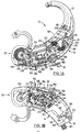
- Figs. 1A and 1B show a hearing aid 10 according to the invention.
- the hearing aid 10 is formed of five main sections, namely an earpiece 12, a receiver module 14, a microphone module 16, an amplifier module 18, and a power or battery module 20.
- the receiver module 14 is assembled as shown in Figs. 2 to 7 inclusive. Specifically, a receiver 22 (which is in fact a small loudspeaker) having three wires 24 connected thereto, is firstly inserted into a standard magnetic shield 30 which protects it on four sides. The front of the receiver 22 is not shielded because of a metal sound tube 32 which projects therefrom, and the top is not protected because of the contacts located there for the wires 24.
- the receiver 22, shielded as shown in Fig. 4, is next inserted into a resilient sleeve 34.
- the sleeve is of rubber or an elastomer and contains five projections.
- One projection 36 extends from each corner of sleeve 34, and a fifth tubular projection 38 covers and extends from the sound tube 32.
- Each projection 36 ends in an enlarged rounded tip 40.
- projection 38 ends in a squared block 42.
- the housing 44 is molded from plastic and has a generally flat bottom 46, a side wall 48, and a generally flat topped lid 50.
- the left and right portions 52, 54 of the sidewall 48 form portions of the sides of the hearing aid when assembled with the remaining modules (to be described) and are contoured for cosmetic appearance.
- the bottom (not shown) of the housing and its lid have sloped edges 55 to accommodate cover plates to be described.
- the housing 44 includes four internal tubular holes 56 to receive and retain the rounded tips 40 of the sleeve 34, and also includes an elongated portion 58 for the tubular projection 38.
- the elongated portion 58 includes, near its tip, internally opposed stub walls 60 having a slot 62 therebetween to receive and trap the square end 42 of the tubular projection 38.
- the rear wall 64 of the housing opposite the elongated portion 58 contains a recess 66 in its upper edge.
- Three flat metal pins 68 project from the upper edge of the recess 66.
- the pins 68 also extend downwardly through the wall 64 and project from the bottom of the housing as shown at 70 in Figs. 5 to 7.
- the receiver 22 wrapped in its resilient sleeve 34 is installed in the housing 44 as shown in Fig. 6.
- the wires 24 are then soldered to the pins 68 in the recess 66.
- the lid 50 is then snapped into place by means of plastic pins 74 which extend downwardly from the edges of the lid and which are received in the top portions of the same holes 56 in housing 44 which receive the resilient tips 40.
- a tab 78 extending downwardly from the lid 50 closes the recess 66 and covers the pins 68 where they connect to the wires 24.
- the complete receiver module 14 is now ready to be installed in the hearing aid.
- a threaded sound spout 80 Projecting from the elongated portion 58 of the housing 44 is a threaded sound spout 80 which communicates internally with the internal passage in tubular projection 38.
- the earpiece 12 has an inner matching thread so that it can be screwed onto the sound spout 80 as shown in Fig. 1A.
- the one-piece resilient sleeve 34 can be replaced by four separate pieces, one fitted over each corner of the receiver 22 and each having a projecting tip shown at 36, 40. In that case a separate resilient tube would be used in place of tubular projection 38.
- a conventional microphone is shown at 82, having three wires 84 connected thereto and having a microphone sound tube 86.
- the microphone 82 is placed in a resilient suspension sleeve 88 as shown in Fig. 9.
- the sleeve 88 (which may be of rubber or elastomer) has two projections 90 at two rear corners thereof and which end in enlarged rounded tips 92.
- the sleeve 88 has a forwardly extending resilient tube 94 which covers the microphone tube 86 and ends in a squared block 96.
- the microphone 82 in its sleeve 88 is fitted into a microphone housing 98 formed of molded plastic and having a generally flat bottom 100, a sidewall 102, and a generally flat topped upper lid 104.
- the sidewall 102 has a rear wall 106 which contains a recess 108 in its upper edge.
- Three flat metal pins 110 project upwardly into the recess 108 and also extend downwardly through the rear wall 106 and project from the bottom 100 as shown at 112.
- the wires 84 are soldered to the pins 110 in the recess 108.
- the tips 92 of the resilient projections 90 are received in tubular holes 93 at the inside rear corners of the housing 98, and the tube 94 extends forwardly so that its squared front end 96 is trapped between two inwardly opposed wall portions 118 at the front of housing 98.
- the inside passage of tube 94 communicates with a port (not shown) in the front wall of housing 98, for sound to reach the microphone 82.
- the housing and lid are shaped to accommodate the microphone on the inside and have sloped outer edges 113 to accommodate the cover plates on the outside.
- the lid 104 is then snapped into place by plastic pins 114 thereon which fit into the tops of the same holes 93 in the housing 98 which receive tips 92.
- a tab 118 projecting downwardly from the rear of lid 104 closes the recess 108 and covers the pins 110 in the recess.
- a downwardly extending projection 120 near the front of the lid contacts the top of tube 84 and prevents it from rising.
- the microphone module 16 is connected to the receiver module 14 by dovetails.
- the microphone module housing sidewall 102 includes an outer wall portion 122 which forms part of the outer wall of the assembled hearing aid, the previously mentioned rear wall 106, and an inner wall portion 124.
- the wall portions 106, 124 join each other at a rounded corner 126 and join the outer wall portion 122 at dovetails 128, 130.
- the sidewall 48 of the receiver module housing contains a front wall portion 132 and an inner wall portion 134 (which forms part of the elongated portion 58) and which meet in a corner 136.
- Wall portions 132, 134 are shaped to match the shape of the walls 106, 124 of the microphone module housing.
- the front wall portion 132 of the receiver module housing contains a dovetail 138 near the side 54 of the receiver module.
- the dovetail 138 cooperates with the dovetail 128 of the microphone module housing 98.
- the inner wall portion 134 of the receiver module housing contains a dovetail 142 near its front and which cooperates with dovetail 130 of the microphone housing module.
- the dovetails 128, 130 of the microphone module 16 can simply be slid into the dovetails 138, 142 of the receiver module 14 and will remain in position there (pending final assembly), because of the tightness of the fit between the parts.
- the rear wall 64 of the receiver module housing contains two dovetail grooves 143, 144. Grooves 143, 144 are used to connect the receiver module 14 to the amplifier module 18 and to the battery module 20, as will be described.
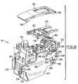
- the amplifier module 18 and certain parts thereof are shown in Figs. 1 and 12 to 14.
- the amplifier module 18 contains (as best shown in Fig. 13) a molded plastic upper frame 150 which extends the full length of the amplifier module.
- the frame 150 includes a molded plastic box 152 to house an on-off switch 154.
- the rear end of the box 152 includes a dovetail 156 to connect to the battery module 20 as will be described.
- a hole 158 in the rear surface of dovetail 156 accommodates a screw 160 which secures the switch 154 in position.
- the other end of the frame 150 includes a molded plastic bearing structure 162 to house and rotatably support a rotary volume control 164.
- the front end of the bearing structure 162 includes a male dovetail 166 shaped to fit snugly within the dovetail groove 144 in the rear end of the receiver module housing 44.
- Electronic components 165 (which form an amplifier) of the amplifier module 18 are mounted on a flexible circuit board 167 (Fig. 14) folded into a "W" shape (as seen from the end) and having inwardly projecting upper ends 168, 170 each carrying two adjustable potentiometers 172.
- the upper ends 168, 170 are folded over and supported on the central portion 174 of the frame 150 and are held in place by a molded plastic retainer plate 176 (Fig. 12).
- Plate 176 snap-fits onto the box structure 152 by means of holes 178 at the end of plate 176 which snap into small pins 180 (Fig. 13) molded onto the box structure 152. At its opposite end plate 176 snaps into the recess 192.
- the plate 176 contains holes 182 which overlie the potentiometers 172 so that a technician can adjust the potentiometers 172 as required.
- a cover plate 184 (Figs. 1A, 1B, 12) is provided, having forks 186 at one end thereof to snap over pin 188 molded in frame 150. The cover plate 184 can be pivoted about pin 188 to expose the potentiometers 172 for adjustment, and can be snapped into its down position to cover potentiometers 172. Cover plate 184 is held in its down position by a dovetail 190 which fits releasably beneath lip 193 at the front end of frame 150.
- circuit board 167 includes a front flap 196 having three openings 198 therein.
- Circuit tracks shown diagrammatically at 200 and which form part of the amplifier circuit extend on printed circuit board 167 to the openings 198.
- the three openings 198 fit over the three projecting pins 70 of the receiver module and are soldered thereto. This connection both forms electrical connections between the amplifier and receiver modules and helps hold the amplifier and receiver modules mechanically together. The soldered connections can easily be unsoldered if repairs are needed.
- the side 194 of the circuit board 167 also contains a rearwardly extending flap 202 containing two openings 204 therein. Circuit tracks shown diagrammatically at 206 and forming part of the amplifier circuit extend to the openings 204. The openings 204 are adapted to fit over tabs 218 extending from the battery module 20, as will be described.
- the battery module 20 is of molded plastic and is shown in Fig. 15.
- the module 20 includes side plates 208 extending rearwardly from and integrally connected to an upper and forwardly extending plate 210.
- the plate 210 terminates at its front end in a male dovetail 212 which fits into the dovetail groove 143 in the rear wall of the receiver housing 44.
- the plate 210 includes a dovetail groove 213 into which a model identification plate 214 (Figs. 1A, 1B) can be slid, to identify the hearing aid in question.
- the side plates 208 each have at their front end a female dovetail 215 (see also Fig. 1A) which accommodates the male dovetail 156 in the rear end of the box 152 of the amplifier module 18.
- the battery module 20 is securely mechanically connected both to the amplifier module 18 and to the receiver module 14, helping to lock all three modules together.
- the dovetails contain stops (not shown) which prevent the modules from being pushed too far and hence ensure their alignment.
- Battery contacts 216 (Fig. 15) are provided, each having a tab 218 projecting from its side.
- the tabs 218 are soldered to circuit tracks (indicated diagrammatically at 206 in Fig. 12) which tabs 218 extend from one side plate 208 of the battery module.
- the holes 204 in circuit board rear flap 202 fit over the tabs 218, so that the circuit board 167 can be soldered to the tabs 218 to provide an electrical connection between the battery and amplifier modules.
- a conventional pivoted battery door 222 is provided to receive a battery and to insert the same into the battery module 20.
- the battery door 222 includes a rounded end 224 having a pivot hole 226 aligned with pin holes 228 in the battery module side plates 208.
- a pin (to be described) is inserted through the respective holes 226, 228 to mount the door 222 to the battery module 20.
- the microphone module 16 is connected to the amplifier module 18 by a separate flexible circuit board 230 shown in Fig. 16.
- the circuit board 230 is soldered to the microphone module pins 112 and is also soldered to side 232 of the circuit board 167, just below the potentiometers 172. If desired, and as shown in Fig. 16, the flexible circuit board 230 can extend rearwardly as shown at 233 and can be connected to a connection plate 234 (Figs. 1A, 1B, 15) in the battery module.
- connection plate 234 is T-shaped in cross-section and slides into a slot 236 in the battery module (the slot 236 is otherwise filled by a filler plate, not shown) and contains connections 238 for a separate audio input to the hearing aid (and for separate power to the hearing aid if desired).
- cover plates 240, 242 (Fig. 17), which also extend generally in the plane of the hearing aid, are snapped into position to cover the exposed sides, top and bottom of the assembled aid.
- Cover plate 240 contains four pins 244 which extend through holes 226, 228, 246 in the assembled hearing aid and which are aligned with matching holes 248 in the cover plate 242.
- Screws 250 may be inserted through the holes 248 into the openings 252 in the pins 244 to secure the cover plates to the hearing aid.
- the cover plates enable a desired cosmetic treatment to be given to the hearing aid while using standard modules in the hearing aid.
- the cover plates also seal the modules against sweat, moisture, dust and the like.
- the edges of the cover plates are also slightly sloped inwardly as shown at 254, for cosmetic appearance and to help hold the modules in position.
- Microphone module dovetails 128,130 (Figs. 1A,11) are connected respectively to receiver module dovetails 138,142 (Figs. 1A,7).
- Receiver module dovetails 143,144 (Figs. 1B,7) are connected respectively to the battery module dovetail 212 (Figs. 1B,15) and the amplifier dovetail 166 (Figs. 1A,12).
- the amplifier dovetail 156 (Figs. 1B,12) is connected to battery module dovetail 215 (Figs. 1A,15).
- each dovetail connection between a pair of connected modules consists of a first surface on one of the connected modules defining a slot having a neck of first width and an interior of second width greater than the first width, and a projection on the other of the connected modules shaped to fit snugly and slidingly into the slot, the projection having an outer surface of third width corresponding to the second width and the projection having a neck of fourth width corresponding to the first width. It will also be clearly seen from the drawings that all of the dovetail connections extend parallel to each other, with their ends being covered by the cover plates 240,242.
Landscapes
- Health & Medical Sciences (AREA)
- General Health & Medical Sciences (AREA)
- Neurosurgery (AREA)
- Otolaryngology (AREA)
- Physics & Mathematics (AREA)
- Engineering & Computer Science (AREA)
- Acoustics & Sound (AREA)
- Signal Processing (AREA)
- Battery Mounting, Suspending (AREA)
- Casings For Electric Apparatus (AREA)
Description
- This invention relates to a modular hearing aid of the kind which normally fits behind the user's ear.
- Hearing aids are traditionally manufactured by electrically connecting together an amplifier, transducers and battery contacts and then packaging this assembly of components into a suitable shell. The shell is tooled specifically to house these components and to protect them from the environmental stresses encountered in day to day use. The performance of a hearing aid is dependent on the integrity of the shell and its ability to provide acoustic isolation between the transducers, protection for the transducers against shock, and protection of all hearing aid components from environmental elements such as moisture and corrosive materials contained in the atmosphere, perspiration, and cosmetic fluids, sprays and powders. While suitable protection may be supplied by a particular hearing aid shell, the need to service the hearing aid components will occasionally require the shell to be opened, thus at the same time compromising the protection provided by the housing.
- In addition, it is sometimes necessary to repair a hearing aid, and the repair process may require replacement of components. When all of the components are interconnected together as one assembly, replacement of parts can be difficult and time consuming.
- As a result of the above problems, various attempts have been made to produce modular hearing aids. Such attempts are shown for examaple in West German Gebrauchsmuster Nos. DE-U-8908003.3 filed June 30, 1989, DE-U-8804745.8 filed April 11, 1988, G8804743.1 filed April 11, 1988, West German Offenlegungsschrift DE-A-3502178 filed January 23, 1985, and European patent application EP-A-0303143 filed January 8, 1988. The above documents show various approaches which have been taken to divide the hearing aid into sections. However these proposals leave much to be desired in terms of mechanical strength, ease of connecting and disconnecting the various sections, and an ability to provide various desired cosmetic treatments to the hearing aid as a whole, a matter which is of great importance to users.
- It is therefore an object of this invention to provide a modular hearing aid in which the major components are individually packaged and yet are ruggedly connected together in a manner which allows for ease of assembly and speedy repair. In one aspect, the present invention provides a modular hearing aid comprising a microphone, a receiver, an amplifier and a battery, characterized in that said microphone is ccntained in a microphone module, said receiver is contained in a receiver module, said amplifier is contained in an amplifier module, and said battery is contained in a battery module, said modules being removably connected together by dovetail connections, each dovetail connection between a pair of connected modules comprising a first surface on one of said connected modules defining a slot having a neck of first width and an interior of second width greater than said first width, and a projection on the other of said connected modules shaped to fit snugly and slidingly into said slot, said projection having an outer surface of third width corresponding to said second width and said projection having a neck of fourth width corresponding to said first width, said dovetail connections all being parallel to each other, said dovetail connections having ends, and a pair of cover plates, one on each side of said hearing aid, said cover plates covering said modules and said ends of said dovetail connections and being removably connected to said assembled modules and substantially covering said modules to help seal said modules against ingress of moisture, dust and the like and to provide a changeable cosmetically attractive appearance for said hearing aid.
- German Offenlegungsschrift DE-A-3502178 discloses a hearing aid formed in two sections, but assembly, disassembly and repair of the hearing aid is still complex. In addition a prominent join line is visible on the face of the hearing aid. French patent FR-A-2,123,728, as well as U.S. patents US-A-3,289,852 and US-A-4,423,465 show modular electronic blocks connected by dovetails, but there is no suggestion that they could be used in hearing aids. There is no way to cover the exposed dovetail faces in French Patent FR-A-2,123,728 or in U.S. patent US-A-4,423,465 and the arrangement shown in U.S. patent US-A-3,289,852 requires a separate dovetail connector piece. German Gebrauchsmuster DE-U-8908003.3 discloses cover plates on a hearing aid but does not suggest the use of a modular construction or dovetail connectors. German Offenlegungsschrift DE-A-3616773 discloses a flexible printed circuit board but does not show it as being connected to tabs on the amplifier, receiver or battery modules of a hearing aid.
- Further objects and advantages of the invention will appear from the following description, taken together with the accompanying drawings.
- In the accompanying drawings:
- Fig. 1A is a top plan view of a hearing aid according to the invention with the modules assembled together;
- Fig. 1B is a bottom plan view of the hearing aid of Fig. 1A;
- Fig. 2 is a perspective view of a receiver for use with the invention;
- Fig. 3 is a perspective view of the receiver of Fig. 2 with magnetic shielding being installed around it;
- Fig. 4 is a perspective view of the receiver of Fig. 3 with a five point rubber suspension sleeve installed over it;
- Fig. 5 is a perspective view of a receiver module housing and lid according to the invention;
- Fig. 6 is a perspective view of the receiver housing of Fig. 5 with the receiver inserted therein;
- Fig. 7 is a perspective view of the receiver housing of Fig. 6 with its lid thereon;
- Fig. 8 is a perspective view of a microphone for use with the invention;
- Fig. 9 is a perspective view of the microphone of Fig. 8 being inserted into a suspension therefor;
- Fig. 10 is a perspective view of the microphone and suspension inserted in a microphone module housing with a lid ready to close the module;
- Fig. 11 is a perspective view of the microphone module housing of Fig. 10 with its lid closed;
- Fig. 12 is a perspective view of an amplifier module for the hearing aid of Fig. 1A;
- Fig. 13 is a perspective view of a frame for the amplifier module of Fig. 12;
- Fig. 14 is an end view of a flexible printed circuit board for the amplifier module of Fig. 12;
- Fig. 15 is a perspective view of the battery module for the hearing aid of Fig. 1A;
- Fig. 16 is a perspective view showing a flexible wiring sheet connecting the microphone and amplifier modules and having an optional connection for direct electrical input to the battery module; and
- Fig. 17 is a perspective view showing cover plates for the hearing aid of Fig. 1A.
- Reference is first made to Figs. 1A and 1B, which show a
hearing aid 10 according to the invention. Thehearing aid 10 is formed of five main sections, namely anearpiece 12, areceiver module 14, amicrophone module 16, anamplifier module 18, and a power orbattery module 20. - The
receiver module 14 is assembled as shown in Figs. 2 to 7 inclusive. Specifically, a receiver 22 (which is in fact a small loudspeaker) having threewires 24 connected thereto, is firstly inserted into a standardmagnetic shield 30 which protects it on four sides. The front of thereceiver 22 is not shielded because of ametal sound tube 32 which projects therefrom, and the top is not protected because of the contacts located there for thewires 24. - The
receiver 22, shielded as shown in Fig. 4, is next inserted into aresilient sleeve 34. The sleeve is of rubber or an elastomer and contains five projections. Oneprojection 36 extends from each corner ofsleeve 34, and a fifthtubular projection 38 covers and extends from thesound tube 32. Eachprojection 36 ends in an enlargedrounded tip 40. Howeverprojection 38 ends in asquared block 42. - The
receiver 22, encased insleeve 34, is next lowered into a housing 44 (Fig. 5) which forms the outer surface of the receiver module. Thehousing 44 is molded from plastic and has a generallyflat bottom 46, aside wall 48, and a generally flat toppedlid 50. The left andright portions sidewall 48 form portions of the sides of the hearing aid when assembled with the remaining modules (to be described) and are contoured for cosmetic appearance. The bottom (not shown) of the housing and its lid have slopededges 55 to accommodate cover plates to be described. - The
housing 44 includes four internaltubular holes 56 to receive and retain therounded tips 40 of thesleeve 34, and also includes anelongated portion 58 for thetubular projection 38. Theelongated portion 58 includes, near its tip, internallyopposed stub walls 60 having aslot 62 therebetween to receive and trap thesquare end 42 of thetubular projection 38. - The
rear wall 64 of the housing opposite theelongated portion 58 contains arecess 66 in its upper edge. Threeflat metal pins 68 project from the upper edge of therecess 66. Thepins 68 also extend downwardly through thewall 64 and project from the bottom of the housing as shown at 70 in Figs. 5 to 7. - In use, the
receiver 22 wrapped in itsresilient sleeve 34 is installed in thehousing 44 as shown in Fig. 6. Thewires 24 are then soldered to thepins 68 in therecess 66. Thelid 50 is then snapped into place by means ofplastic pins 74 which extend downwardly from the edges of the lid and which are received in the top portions of thesame holes 56 inhousing 44 which receive theresilient tips 40. Atab 78 extending downwardly from thelid 50 closes therecess 66 and covers thepins 68 where they connect to thewires 24. Thecomplete receiver module 14 is now ready to be installed in the hearing aid. - Projecting from the
elongated portion 58 of thehousing 44 is a threadedsound spout 80 which communicates internally with the internal passage intubular projection 38. Theearpiece 12 has an inner matching thread so that it can be screwed onto thesound spout 80 as shown in Fig. 1A. - If desired, the one-piece
resilient sleeve 34 can be replaced by four separate pieces, one fitted over each corner of thereceiver 22 and each having a projecting tip shown at 36, 40. In that case a separate resilient tube would be used in place oftubular projection 38. - The
microphone module 16 will next be described, with reference to Figs. 8 to 11. In Fig. 8 a conventional microphone is shown at 82, having threewires 84 connected thereto and having amicrophone sound tube 86. Themicrophone 82 is placed in aresilient suspension sleeve 88 as shown in Fig. 9. The sleeve 88 (which may be of rubber or elastomer) has twoprojections 90 at two rear corners thereof and which end in enlargedrounded tips 92. At its front thesleeve 88 has a forwardly extendingresilient tube 94 which covers themicrophone tube 86 and ends in asquared block 96. - The
microphone 82 in itssleeve 88 is fitted into amicrophone housing 98 formed of molded plastic and having a generallyflat bottom 100, asidewall 102, and a generally flat toppedupper lid 104. Thesidewall 102 has arear wall 106 which contains arecess 108 in its upper edge. Three flat metal pins 110 project upwardly into therecess 108 and also extend downwardly through therear wall 106 and project from the bottom 100 as shown at 112. Thewires 84 are soldered to the pins 110 in therecess 108. Thetips 92 of theresilient projections 90 are received intubular holes 93 at the inside rear corners of thehousing 98, and thetube 94 extends forwardly so that its squaredfront end 96 is trapped between two inwardly opposedwall portions 118 at the front ofhousing 98. The inside passage oftube 94 communicates with a port (not shown) in the front wall ofhousing 98, for sound to reach themicrophone 82. The housing and lid are shaped to accommodate the microphone on the inside and have slopedouter edges 113 to accommodate the cover plates on the outside. - The
lid 104 is then snapped into place byplastic pins 114 thereon which fit into the tops of thesame holes 93 in thehousing 98 which receivetips 92. Atab 118 projecting downwardly from the rear oflid 104 closes therecess 108 and covers the pins 110 in the recess. A downwardly extendingprojection 120 near the front of the lid contacts the top oftube 84 and prevents it from rising. - The
microphone module 16 is connected to thereceiver module 14 by dovetails. Specifically, the microphonemodule housing sidewall 102 includes anouter wall portion 122 which forms part of the outer wall of the assembled hearing aid, the previously mentionedrear wall 106, and aninner wall portion 124. Thewall portions rounded corner 126 and join theouter wall portion 122 at dovetails 128, 130. - The
sidewall 48 of the receiver module housing contains afront wall portion 132 and an inner wall portion 134 (which forms part of the elongated portion 58) and which meet in acorner 136.Wall portions walls front wall portion 132 of the receiver module housing contains adovetail 138 near theside 54 of the receiver module. Thedovetail 138 cooperates with thedovetail 128 of themicrophone module housing 98. Theinner wall portion 134 of the receiver module housing contains adovetail 142 near its front and which cooperates withdovetail 130 of the microphone housing module. - Thus, as shown in Figs. 1A, 1B, the dovetails 128, 130 of the
microphone module 16 can simply be slid into the dovetails 138, 142 of thereceiver module 14 and will remain in position there (pending final assembly), because of the tightness of the fit between the parts. - For a similar purpose, the
rear wall 64 of the receiver module housing contains two dovetailgrooves Grooves receiver module 14 to theamplifier module 18 and to thebattery module 20, as will be described. - The
amplifier module 18 and certain parts thereof are shown in Figs. 1 and 12 to 14. Theamplifier module 18 contains (as best shown in Fig. 13) a molded plasticupper frame 150 which extends the full length of the amplifier module. At its rear end theframe 150 includes a moldedplastic box 152 to house an on-off switch 154. The rear end of thebox 152 includes adovetail 156 to connect to thebattery module 20 as will be described. Ahole 158 in the rear surface ofdovetail 156 accommodates ascrew 160 which secures theswitch 154 in position. - The other end of the
frame 150 includes a moldedplastic bearing structure 162 to house and rotatably support arotary volume control 164. The front end of thebearing structure 162 includes amale dovetail 166 shaped to fit snugly within thedovetail groove 144 in the rear end of thereceiver module housing 44. - Electronic components 165 (which form an amplifier) of the
amplifier module 18 are mounted on a flexible circuit board 167 (Fig. 14) folded into a "W" shape (as seen from the end) and having inwardly projecting upper ends 168, 170 each carrying twoadjustable potentiometers 172. The upper ends 168, 170 are folded over and supported on thecentral portion 174 of theframe 150 and are held in place by a molded plastic retainer plate 176 (Fig. 12).Plate 176 snap-fits onto thebox structure 152 by means ofholes 178 at the end ofplate 176 which snap into small pins 180 (Fig. 13) molded onto thebox structure 152. At itsopposite end plate 176 snaps into therecess 192. - The
plate 176 containsholes 182 which overlie thepotentiometers 172 so that a technician can adjust thepotentiometers 172 as required. A cover plate 184 (Figs. 1A, 1B, 12) is provided, havingforks 186 at one end thereof to snap overpin 188 molded inframe 150. Thecover plate 184 can be pivoted aboutpin 188 to expose thepotentiometers 172 for adjustment, and can be snapped into its down position to coverpotentiometers 172.Cover plate 184 is held in its down position by adovetail 190 which fits releasably beneathlip 193 at the front end offrame 150. - As shown in Fig. 12, one
side 194 ofcircuit board 167 includes a front flap 196 having threeopenings 198 therein. Circuit tracks shown diagrammatically at 200 and which form part of the amplifier circuit extend on printedcircuit board 167 to theopenings 198. When the hearing aid is assembled, the threeopenings 198 fit over the three projectingpins 70 of the receiver module and are soldered thereto. This connection both forms electrical connections between the amplifier and receiver modules and helps hold the amplifier and receiver modules mechanically together. The soldered connections can easily be unsoldered if repairs are needed. - The
side 194 of thecircuit board 167 also contains a rearwardly extendingflap 202 containing twoopenings 204 therein. Circuit tracks shown diagrammatically at 206 and forming part of the amplifier circuit extend to theopenings 204. Theopenings 204 are adapted to fit overtabs 218 extending from thebattery module 20, as will be described. - The
battery module 20 is of molded plastic and is shown in Fig. 15. Themodule 20 includesside plates 208 extending rearwardly from and integrally connected to an upper and forwardly extendingplate 210. Theplate 210 terminates at its front end in amale dovetail 212 which fits into thedovetail groove 143 in the rear wall of thereceiver housing 44. In its outer surface theplate 210 includes adovetail groove 213 into which a model identification plate 214 (Figs. 1A, 1B) can be slid, to identify the hearing aid in question. - Similarly, the
side plates 208 each have at their front end a female dovetail 215 (see also Fig. 1A) which accommodates themale dovetail 156 in the rear end of thebox 152 of theamplifier module 18. Thus thebattery module 20 is securely mechanically connected both to theamplifier module 18 and to thereceiver module 14, helping to lock all three modules together. It will be noted that the dovetails contain stops (not shown) which prevent the modules from being pushed too far and hence ensure their alignment. - Battery contacts 216 (Fig. 15) are provided, each having a
tab 218 projecting from its side. Thetabs 218 are soldered to circuit tracks (indicated diagrammatically at 206 in Fig. 12) whichtabs 218 extend from oneside plate 208 of the battery module. Theholes 204 in circuit boardrear flap 202 fit over thetabs 218, so that thecircuit board 167 can be soldered to thetabs 218 to provide an electrical connection between the battery and amplifier modules. - A conventional pivoted
battery door 222 is provided to receive a battery and to insert the same into thebattery module 20. Thebattery door 222 includes arounded end 224 having apivot hole 226 aligned withpin holes 228 in the batterymodule side plates 208. A pin (to be described) is inserted through therespective holes door 222 to thebattery module 20. - The
microphone module 16 is connected to theamplifier module 18 by a separateflexible circuit board 230 shown in Fig. 16. Thecircuit board 230 is soldered to the microphone module pins 112 and is also soldered toside 232 of thecircuit board 167, just below thepotentiometers 172. If desired, and as shown in Fig. 16, theflexible circuit board 230 can extend rearwardly as shown at 233 and can be connected to a connection plate 234 (Figs. 1A, 1B, 15) in the battery module. Theconnection plate 234 is T-shaped in cross-section and slides into aslot 236 in the battery module (theslot 236 is otherwise filled by a filler plate, not shown) and containsconnections 238 for a separate audio input to the hearing aid (and for separate power to the hearing aid if desired). - After the hearing aid has been assembled as shown in Fig. 1, cover
plates 240, 242 (Fig. 17), which also extend generally in the plane of the hearing aid, are snapped into position to cover the exposed sides, top and bottom of the assembled aid.Cover plate 240 contains fourpins 244 which extend throughholes holes 248 in thecover plate 242.Screws 250 may be inserted through theholes 248 into theopenings 252 in thepins 244 to secure the cover plates to the hearing aid. The cover plates enable a desired cosmetic treatment to be given to the hearing aid while using standard modules in the hearing aid. The cover plates also seal the modules against sweat, moisture, dust and the like. The edges of the cover plates are also slightly sloped inwardly as shown at 254, for cosmetic appearance and to help hold the modules in position. - In summary, it will be seen from the drawings that the various modules, namely the microphone module, reciever module, amplifier module and battery module, are connected together by the following dovetails. Microphone module dovetails 128,130 (Figs. 1A,11) are connected respectively to receiver module dovetails 138,142 (Figs. 1A,7). Receiver module dovetails 143,144 (Figs. 1B,7) are connected respectively to the battery module dovetail 212 (Figs. 1B,15) and the amplifier dovetail 166 (Figs. 1A,12). Finally, the amplifier dovetail 156 (Figs. 1B,12) is connected to battery module dovetail 215 (Figs. 1A,15). It will be clearly seen from the drawings that each dovetail connection between a pair of connected modules consists of a first surface on one of the connected modules defining a slot having a neck of first width and an interior of second width greater than the first width, and a projection on the other of the connected modules shaped to fit snugly and slidingly into the slot, the projection having an outer surface of third width corresponding to the second width and the projection having a neck of fourth width corresponding to the first width. It will also be clearly seen from the drawings that all of the dovetail connections extend parallel to each other, with their ends being covered by the cover plates 240,242.
Claims (10)
- A modular hearing aid (10) comprising a microphone (82), a receiver (22), an amplifier (165) and a battery, characterized in that(a) said microphone (82) is contained in a microphone module (16), said receiver (22) is contained in a receiver module (14), said amplifier (165) is contained in an amplifier module (18), and said battery is contained in a battery module (20),(b) said modules (14, 16, 18, 20) being removably connected together by dovetail connections (128, 130, 138, 142, 143, 144, 156, 166, 212, 215), each dovetail connection (128, 130, 138, 142, 143, 144, 156, 166, 212, 215) between a pair of connected modules (14, 16, 18, 20) compsising a first surface on one of said connected modules defining a slot (138, 142, 143, 144, 215) having a neck of first width and an interior of second width greater than said first width, and a projection (128, 130, 156, 166, 212) on the other of said connected modules shaped to fit snugly and slidingly into said slot, said projection having an outer surface of third width corresponding to said second width and said projection having a neck of fourth width corresponding to said first width, said dovetail connections (128, 130, 138, 142, 143, 144, 1S6, 166, 212, 215) all being parallel to each other, said dovetail connections (128, 130, 138, 142, 143, 144, 156, 166, 212, 215) having ends,(c) and comprising a pair of cover plates (240, 242), one on each side of said hearing aid (10), said cover plates (240, 242) covering said modules (14, 16, 18, 20) and said ends of said dovetail connections (128, 130, 138, 142, 143, 144, 156, 166, 212, 215) and being removably connected (244, 250) to said assembled modules (14, 16, 18, 20) and substantially covering said modules (14, 16, 18, 20) to help seal said modules (14, 16, 18, 20) against ingress of moisture, dust and the like and to provide a changeable cosmetically attractive appearance for said hearing aid (10).
- A hearing aid (10) according to claim 1 wherein said modules (14, 16, 18, 20) each have edge walls which together form edge walls of said hearing aid (10).
- A hearing aid according to claim 2 and including electric circuit means (167, 230) interconnecting said modules (14, 16, 18, 20), and wherein said microphone module (16) is removably connected to said receiver module (14) by a said dovetail connection (128, 130, 138, 142), said amplifier module (18) is removably connected to said receiver module (14) by a said dovetail connection (144, 166), and said battery module (20) is removably connected to both said receiver and amplifier modules (14, 18) by said dovetail connections (143, 156, 212, 215).
- A hearing aid according to claim 2 wherein said circuit means (167, 230) includes a flexible printed circuit board (167) forming part of said amplifier module (18) and having a flap (196) which projects over said receiver module (14), said flap having openings (198) therein, said receiver module having electrical connection means (70) projecting through said openings (198) and soldered to said flap (196).
- A hearing aid according to claim 3 wherein said amplifier module (18) includes a flexible printed circuit board (167) forming part of said circuit means (167, 230) and having a flap (202) which projects over said battery module (20), said flap (202) having openings (204) therein, said battery module (20) having electrical connection means (218) projecting through said openings (204) and soldered to said flap (202).
- A hearing aid according to claim 3 wherein said receiver module (14) includes a receiver housing (44), said receiver housing (44) including a bottom wall (46), an encircling sidewall (48) extending from said bottom wall (46), and an upper edge, and wherein said sidewall (48) has a recess (66) in said upper edge, a plurality of metal tabs (68) extending through said sidewall (48) and having first ends extending into said recess (66) and second ends (70) projecting outwardly from said sidewall (48) adjacent said bottom wall (46), said first ends of said tabs (68) being electrically connected to said receiver (22), and a lid (50) removably fitted over said upper edge of said sidewall (48) to close said housing (44), said lid (50) having a flap (78) covering said recess (66), said second ends (70) of said tabs (68) being electrically connected to said amplifier module (18).
- A hearing aid according to claim 6 wherein said amplifier (165) includes a flexible printed circuit board (167) forming a part of said circuit means (167, 230), said printed circuit board (167) having a flap (196) projecting over said second ends (70) of said tabs (68) of said receiver module (14), said flap having openings (198) therein, said second ends (70) of said tabs (68) projecting through said openings (198) and being soldered to said flap (196).
- A hearing aid according to claim 1 wherein said microphone module (16) includes a housing (98), said housing (98) including a bottom wall (100), and encircling sidewall (102) connected to said bottom wall (100) and having an upper edge, and wherein said upper edge has a recess (108) therein, a plurality of metal tabs (110) extending through said sidewall (102) and having first ends projecting into said recess (108) and second ends (112) projecting from said sidewall (102) adjacent said bottom wall (100), said first ends being electrically connected to said microphone (82), said second ends (112) being electrically ccnnected to said amplifier (165).
- A hearing aid according to claim 8 wherein said circuit means (167, 230) includes a flexible printed circuit board (230) connected to said second ends (112) of said tabs (110) and extending over said receiver module (14) and electrically connected to said amplifier module (18).
- A hearing aid according to claim 1 wherein said battery module (20) contains connection means (238) adapted to receive a direct electrical output.
Applications Claiming Priority (2)
| Application Number | Priority Date | Filing Date | Title |
|---|---|---|---|
| CA2014960 | 1990-04-19 | ||
| CA002014960A CA2014960C (en) | 1990-04-19 | 1990-04-19 | Modular hearing aid |
Publications (3)
| Publication Number | Publication Date |
|---|---|
| EP0453200A2 EP0453200A2 (en) | 1991-10-23 |
| EP0453200A3 EP0453200A3 (en) | 1991-11-13 |
| EP0453200B1 true EP0453200B1 (en) | 1995-08-02 |
Family
ID=4144780
Family Applications (1)
| Application Number | Title | Priority Date | Filing Date |
|---|---|---|---|
| EP91303281A Expired - Lifetime EP0453200B1 (en) | 1990-04-19 | 1991-04-12 | Modular hearing aid |
Country Status (4)
| Country | Link |
|---|---|
| US (1) | US5204917A (en) |
| EP (1) | EP0453200B1 (en) |
| CA (1) | CA2014960C (en) |
| DE (1) | DE69111668T2 (en) |
Cited By (2)
| Publication number | Priority date | Publication date | Assignee | Title |
|---|---|---|---|---|
| US7443992B2 (en) | 2004-04-15 | 2008-10-28 | Starkey Laboratories, Inc. | Method and apparatus for modular hearing aid |
| EP2015605A2 (en) | 2007-07-09 | 2009-01-14 | Siemens Audiologische Technik GmbH | Hearing aid |
Families Citing this family (74)
| Publication number | Priority date | Publication date | Assignee | Title |
|---|---|---|---|---|
| US5757932A (en) * | 1993-09-17 | 1998-05-26 | Audiologic, Inc. | Digital hearing aid system |
| US5838906A (en) | 1994-10-17 | 1998-11-17 | The Regents Of The University Of California | Distributed hypermedia method for automatically invoking external application providing interaction and display of embedded objects within a hypermedia document |
| GB2305067A (en) * | 1995-09-02 | 1997-03-26 | A & M Hearing Ltd | Hearing aid having hinged housing |
| US5915031A (en) * | 1996-04-30 | 1999-06-22 | Siemens Hearing Instruments, Inc. | Modularized hearing aid circuit structure |
| DE69836635T2 (en) * | 1997-07-18 | 2007-09-27 | Resound Corp., Redwood City | BEHIND-THE-EAR hearing aid |
| EP0847227B1 (en) * | 1998-03-02 | 2003-08-27 | Phonak Ag | Hearing aid |
| DK1120010T3 (en) * | 1998-10-07 | 2010-08-02 | Oticon As | Hearing aid |
| AU2068701A (en) * | 1999-12-10 | 2001-06-18 | Sonic Innovations, Inc. | Hearing device shell with integrated windscreen and microphone suspension |
| US7181035B2 (en) * | 2000-11-22 | 2007-02-20 | Sonion Nederland B.V. | Acoustical receiver housing for hearing aids |
| DE60103934T2 (en) * | 2000-12-20 | 2005-07-07 | Oticon A/S | COMMUNICATIONS DEVICE |
| US7239714B2 (en) * | 2001-10-09 | 2007-07-03 | Sonion Nederland B.V. | Microphone having a flexible printed circuit board for mounting components |
| DE10228828C1 (en) * | 2002-06-27 | 2003-10-16 | Siemens Audiologische Technik | Modular hearing aid has respective microphones in replaceable microphone module and main hearing aid module |
| DE10228826A1 (en) * | 2002-06-27 | 2004-01-29 | Siemens Audiologische Technik Gmbh | Acoustic module for a hearing aid |
| DK1404151T3 (en) * | 2002-09-25 | 2017-09-18 | Sivantos Gmbh | In-ear portable hearing aid with a housing |
| DE10260303B3 (en) | 2002-12-20 | 2004-06-17 | Siemens Audiologische Technik Gmbh | Microphone module for hearing aid, has several microphones attached to common carrier and electrically connected via 3-dimensional conductor paths |
| JP2004279231A (en) * | 2003-03-17 | 2004-10-07 | Minebea Co Ltd | R/d converter |
| US7460680B2 (en) * | 2003-06-30 | 2008-12-02 | Siemens Hearing Instruments, Inc. | Feedback reducing receiver mount and assembly |
| US7532733B2 (en) * | 2003-06-30 | 2009-05-12 | Siemens Hearing Instruments, Inc. | Feedback reducing receiver mount and assembly |
| DE10343292B3 (en) * | 2003-09-18 | 2004-12-02 | Siemens Audiologische Technik Gmbh | Hearing aid e.g. for hearing impaired people, without separate microphone housing, has hearing aid housing and a microphone housing which are formed from a one-piece with housing having cover for acoustic isolation |
| CN1860825A (en) * | 2003-10-03 | 2006-11-08 | 奥迪康有限公司 | Hearing aid with printed circuit board and microphone suspension |
| EP1692914B1 (en) * | 2003-12-05 | 2016-09-21 | Oticon A/S | Communication device with receiver enclosure |
| US8788050B2 (en) * | 2003-12-22 | 2014-07-22 | Cochlear Limited | Hearing prosthesis system having interchangeable housings |
| US7660633B2 (en) | 2003-12-24 | 2010-02-09 | Cochlear Limited | Transformable speech processor module for a hearing prosthesis |
| US7561920B2 (en) * | 2004-04-02 | 2009-07-14 | Advanced Bionics, Llc | Electric and acoustic stimulation fitting systems and methods |
| WO2006023920A1 (en) | 2004-08-18 | 2006-03-02 | Micro Ear Technology, Inc. D/B/A Micro-Tech | Wireless communications adapter for a hearing assistance device |
| US9774961B2 (en) | 2005-06-05 | 2017-09-26 | Starkey Laboratories, Inc. | Hearing assistance device ear-to-ear communication using an intermediate device |
| US8041066B2 (en) | 2007-01-03 | 2011-10-18 | Starkey Laboratories, Inc. | Wireless system for hearing communication devices providing wireless stereo reception modes |
| US20090222064A1 (en) * | 2005-07-08 | 2009-09-03 | Advanced Bionics, Llc | Autonomous Autoprogram Cochlear Implant |
| US20070036378A1 (en) * | 2005-07-15 | 2007-02-15 | Knowles Electronics, Llc | Shock resistant and vibration isolated electroacoustical transducer assembly |
| WO2007013853A1 (en) * | 2005-07-28 | 2007-02-01 | Siemens Audiologische Technik Gmbh | Microphone carrier for hearing aid microphones |
| US8265765B2 (en) * | 2005-12-08 | 2012-09-11 | Cochlear Limited | Multimodal auditory fitting |
| US7756284B2 (en) * | 2006-01-30 | 2010-07-13 | Songbird Hearing, Inc. | Hearing aid circuit with integrated switch and battery |
| US20070195981A1 (en) * | 2006-02-23 | 2007-08-23 | Le Anthony D | Behind-the-ear hearing aid with integrally-molded instrument case |
| US20060171550A1 (en) * | 2006-03-17 | 2006-08-03 | Audina Hearing Instruments, Inc. | BTE hearing aid component and hearing aid comprising same |
| AU2006340658B2 (en) * | 2006-03-21 | 2010-05-20 | Widex A/S | Interchangeable attachment means for attaching a conductor to a hearing aid |
| US8027638B2 (en) * | 2006-03-29 | 2011-09-27 | Micro Ear Technology, Inc. | Wireless communication system using custom earmold |
| US8818517B2 (en) | 2006-05-05 | 2014-08-26 | Advanced Bionics Ag | Information processing and storage in a cochlear stimulation system |
| DE102006023722A1 (en) * | 2006-05-19 | 2007-11-22 | Siemens Audiologische Technik Gmbh | Hearing device with screwed closure device |
| US7742613B2 (en) * | 2006-06-21 | 2010-06-22 | Phonak Ag | Connecting means for housings of hearing devices |
| US8208642B2 (en) | 2006-07-10 | 2012-06-26 | Starkey Laboratories, Inc. | Method and apparatus for a binaural hearing assistance system using monaural audio signals |
| US7995771B1 (en) | 2006-09-25 | 2011-08-09 | Advanced Bionics, Llc | Beamforming microphone system |
| US7864968B2 (en) * | 2006-09-25 | 2011-01-04 | Advanced Bionics, Llc | Auditory front end customization |
| DE102007010014B4 (en) * | 2007-03-01 | 2011-02-24 | Siemens Audiologische Technik Gmbh | Hearing aid with basic structure |
| EP2023663B1 (en) | 2007-08-07 | 2011-02-23 | Bernafon AG | Behind the ear hearing aid part with exchangeable cover |
| DE102007045460B3 (en) * | 2007-09-24 | 2009-06-04 | Siemens Medical Instruments Pte. Ltd. | Hearing device with differently mounted control |
| DE102007061310A1 (en) | 2007-12-19 | 2009-06-25 | Siemens Medical Instruments Pte. Ltd. | Electroacoustic miniature transducer with holding means for installation in a hearing aid |
| DE102008044642A1 (en) * | 2008-08-27 | 2010-03-04 | Siemens Medical Instruments Pte. Ltd. | Electrical circuit, small electrical appliance, in particular a hearing aid, with the electrical circuit and use of the electrical circuit to produce the small electrical appliance |
| DK2324643T3 (en) * | 2008-09-18 | 2014-11-17 | Siemens Medical Instr Pte Ltd | A hearing aid faceplate arrangement |
| EP2219392B1 (en) * | 2009-02-17 | 2018-05-16 | Sivantos Pte. Ltd. | Microphone module for a hearing device |
| EP2229009B1 (en) * | 2009-03-09 | 2013-10-30 | Oticon A/S | Hearing aid |
| DK2285136T3 (en) * | 2009-07-15 | 2016-01-25 | Sivantos Pte Ltd | Hearing aid with replaceable phone |
| US8781144B2 (en) * | 2009-08-17 | 2014-07-15 | Phonak Ag | Attachment of a hook to a hearing device |
| US9420385B2 (en) | 2009-12-21 | 2016-08-16 | Starkey Laboratories, Inc. | Low power intermittent messaging for hearing assistance devices |
| DE102010009702A1 (en) * | 2010-03-01 | 2011-10-06 | Siemens Medical Instruments Pte. Ltd. | Hearing device with a guide element, in particular a sound tube |
| US8374368B2 (en) * | 2010-03-25 | 2013-02-12 | Sonic Innovations, Inc. | Hearing aid device with a volume control |
| US8503708B2 (en) | 2010-04-08 | 2013-08-06 | Starkey Laboratories, Inc. | Hearing assistance device with programmable direct audio input port |
| US8442252B2 (en) | 2010-09-30 | 2013-05-14 | Audiotoniq, Inc. | Behind-the-ear hearing aid with interchangeable ear hook and ear tube |
| US9179228B2 (en) * | 2011-12-09 | 2015-11-03 | Sophono, Inc. | Systems devices, components and methods for providing acoustic isolation between microphones and transducers in bone conduction magnetic hearing aids |
| CA2943534A1 (en) * | 2013-04-05 | 2014-10-09 | Jerry HARVEY | Canalphone coupler system and method |
| DK3422741T3 (en) * | 2014-04-07 | 2020-08-03 | Oticon As | HEARING AID DEVICE THAT HAS A BATTERY DRAWER |
| US10003379B2 (en) | 2014-05-06 | 2018-06-19 | Starkey Laboratories, Inc. | Wireless communication with probing bandwidth |
| US10827283B2 (en) | 2014-08-19 | 2020-11-03 | Starkey Laboratories, Inc. | Flexible hearing aid circuit with motherboard and peripheral attachments |
| CN107079226A (en) * | 2014-10-09 | 2017-08-18 | 索诺亚公司 | Auditory prosthesis |
| DE102015203203B3 (en) * | 2015-02-23 | 2016-07-28 | Sivantos Pte. Ltd. | Hearing aid and plug connection for such |
| CN106878896B (en) * | 2015-09-21 | 2021-03-02 | 奥迪康有限公司 | Hearing device |
| US20190268705A1 (en) | 2018-02-28 | 2019-08-29 | Starkey Laboratories, Inc. | Modular hearing assistance system |
| US11716580B2 (en) | 2018-02-28 | 2023-08-01 | Starkey Laboratories, Inc. | Health monitoring with ear-wearable devices and accessory devices |
| US10939216B2 (en) | 2018-02-28 | 2021-03-02 | Starkey Laboratories, Inc. | Health monitoring with ear-wearable devices and accessory devices |
| CN109068253B (en) * | 2018-07-12 | 2020-09-11 | 泉州科源三维设计有限责任公司 | Hearing aid protection dust-proof device |
| US10911878B2 (en) | 2018-12-21 | 2021-02-02 | Starkey Laboratories, Inc. | Modularization of components of an ear-wearable device |
| WO2021041843A1 (en) | 2019-08-30 | 2021-03-04 | Starkey Laboratories, Inc. | Hearing instruments with receiver positioned posterior to battery |
| US11140469B1 (en) | 2021-05-03 | 2021-10-05 | Bose Corporation | Open-ear headphone |
| US11856356B2 (en) | 2022-01-28 | 2023-12-26 | Bose Corporation | Open-ear headphone |
| US20250247655A1 (en) * | 2024-01-31 | 2025-07-31 | Starkey Laboratories, Inc. | Microphone suspension for mechanical feedback reduction in hearing devices |
Family Cites Families (12)
| Publication number | Priority date | Publication date | Assignee | Title |
|---|---|---|---|---|
| US3289852A (en) * | 1965-04-07 | 1966-12-06 | Sangamo Electric Co | Flexible printed circuit chassis |
| FR2123728A5 (en) * | 1971-01-29 | 1972-09-15 | App Const | |
| DE2906088A1 (en) * | 1979-02-17 | 1980-08-28 | Licentia Gmbh | Loudspeaker box mount for detachable connections - has matching dovetail connectors and socket for plugs |
| NL8101286A (en) * | 1981-03-17 | 1982-10-18 | Philips Nv | IMPROVED SUSPENSION FOR A PHONE IN A HEARING AID. |
| US4423465A (en) * | 1981-09-30 | 1983-12-27 | Teng Ching Weng | Combination electronic circuit element with multidirectionally adjustable joints |
| DE3428166A1 (en) * | 1984-07-31 | 1986-02-13 | micro-technic Hörgeräte GmbH, 7000 Stuttgart | Hearing aid to be worn in the auditory canal for persons with impaired or severely impaired hearing |
| DE3616773A1 (en) * | 1986-05-17 | 1987-11-19 | Bosch Gmbh Robert | Hearing aid |
| US4870688A (en) * | 1986-05-27 | 1989-09-26 | Barry Voroba | Mass production auditory canal hearing aid |
| DE8713086U1 (en) * | 1987-09-29 | 1989-01-26 | Siemens AG, 1000 Berlin und 8000 München | Hearing aid with housing |
| DE8804743U1 (en) * | 1988-04-11 | 1989-08-10 | Siemens AG, 1000 Berlin und 8000 München | Hearing aid, especially a hearing aid with a housing to be worn behind the ear |
| US5001762A (en) * | 1989-03-31 | 1991-03-19 | Resistance Technology, Inc. | Miniature modular volume control and integrated circuit assembly for use with a hearing air |
| DE8908003U1 (en) * | 1989-06-30 | 1989-08-10 | Robert Bosch Gmbh, 7000 Stuttgart | Housing for a hearing aid to be worn behind the ear |
-
1990
- 1990-04-19 CA CA002014960A patent/CA2014960C/en not_active Expired - Lifetime
-
1991
- 1991-04-12 EP EP91303281A patent/EP0453200B1/en not_active Expired - Lifetime
- 1991-04-12 DE DE69111668T patent/DE69111668T2/en not_active Expired - Fee Related
- 1991-04-17 US US07/686,368 patent/US5204917A/en not_active Expired - Lifetime
Cited By (3)
| Publication number | Priority date | Publication date | Assignee | Title |
|---|---|---|---|---|
| US7443992B2 (en) | 2004-04-15 | 2008-10-28 | Starkey Laboratories, Inc. | Method and apparatus for modular hearing aid |
| EP2015605A2 (en) | 2007-07-09 | 2009-01-14 | Siemens Audiologische Technik GmbH | Hearing aid |
| DE102007031872A1 (en) | 2007-07-09 | 2009-01-15 | Siemens Audiologische Technik Gmbh | hearing Aid |
Also Published As
| Publication number | Publication date |
|---|---|
| CA2014960C (en) | 1995-07-25 |
| EP0453200A2 (en) | 1991-10-23 |
| DE69111668T2 (en) | 1997-05-07 |
| DE69111668D1 (en) | 1995-09-07 |
| EP0453200A3 (en) | 1991-11-13 |
| CA2014960A1 (en) | 1991-10-19 |
| US5204917A (en) | 1993-04-20 |
Similar Documents
| Publication | Publication Date | Title |
|---|---|---|
| EP0453200B1 (en) | Modular hearing aid | |
| CA1274184A (en) | Modular hearing aid with lid hinged to faceplate | |
| USD325723S (en) | Housing for an electrical plug receptacle | |
| USD411826S (en) | Weatherproof electrical enclosure | |
| USD402275S (en) | Enclosure for electronic and electric components | |
| US5201008A (en) | Modular hearing aid with lid hinged to faceplate | |
| USD400512S (en) | Enclosure for electronic and electric components | |
| USD410226S (en) | Electrical connector terminal | |
| USD439877S1 (en) | Battery housing | |
| USD408789S (en) | Electrical connector housing | |
| USD416873S (en) | Housing for outdoor electrical equipment | |
| USD366247S (en) | Housing for electrical and/or electronic equipment | |
| USD416232S (en) | External mounting closed electrical connector box | |
| USD408353S (en) | Electrical connector terminal | |
| AU2591595A (en) | Impedance circuit for a miniature hearing aid | |
| USD421961S (en) | Electrical receptacle housing | |
| CA2159059A1 (en) | Electrical receptacle assembly with interference fitting and latching parts | |
| USD324027S (en) | Electrical connector housing | |
| USD324031S (en) | Electrical connector housing | |
| USD409576S (en) | Electrical connector housing | |
| USD328590S (en) | Electrical connector housing | |
| USD288434S (en) | Housing for electrical circuit which provides an interface between a computer and a television set, or the like | |
| USD429219S (en) | Electrical connector | |
| USD444452S1 (en) | Cable sealing plug | |
| USD397995S (en) | Weatherproof electrical enclosure |
Legal Events
| Date | Code | Title | Description |
|---|---|---|---|
| PUAI | Public reference made under article 153(3) epc to a published international application that has entered the european phase |
Free format text: ORIGINAL CODE: 0009012 |
|
| PUAL | Search report despatched |
Free format text: ORIGINAL CODE: 0009013 |
|
| AK | Designated contracting states |
Kind code of ref document: A2 Designated state(s): CH DE DK FR GB IT LI NL |
|
| AK | Designated contracting states |
Kind code of ref document: A3 Designated state(s): CH DE DK FR GB IT LI NL |
|
| 17P | Request for examination filed |
Effective date: 19920313 |
|
| 17Q | First examination report despatched |
Effective date: 19931109 |
|
| GRAA | (expected) grant |
Free format text: ORIGINAL CODE: 0009210 |
|
| AK | Designated contracting states |
Kind code of ref document: B1 Designated state(s): CH DE DK FR GB IT LI NL |
|
| PG25 | Lapsed in a contracting state [announced via postgrant information from national office to epo] |
Ref country code: IT Free format text: LAPSE BECAUSE OF FAILURE TO SUBMIT A TRANSLATION OF THE DESCRIPTION OR TO PAY THE FEE WITHIN THE PRE;WARNING: LAPSES OF ITALIAN PATENTS WITH EFFECTIVE DATE BEFORE 2007 MAY HAVE OCCURRED AT ANY TIME BEFORE 2007. THE CORRECT EFFECTIVE DATE MAY BE DIFFERENT FROM THE ONE RECORDED.SCRIBED TIME-LIMIT Effective date: 19950802 Ref country code: DK Effective date: 19950802 Ref country code: CH Effective date: 19950802 Ref country code: NL Free format text: LAPSE BECAUSE OF FAILURE TO SUBMIT A TRANSLATION OF THE DESCRIPTION OR TO PAY THE FEE WITHIN THE PRESCRIBED TIME-LIMIT Effective date: 19950802 Ref country code: LI Effective date: 19950802 |
|
| REF | Corresponds to: |
Ref document number: 69111668 Country of ref document: DE Date of ref document: 19950907 |
|
| EN | Fr: translation not filed | ||
| NLV1 | Nl: lapsed or annulled due to failure to fulfill the requirements of art. 29p and 29m of the patents act | ||
| ET | Fr: translation filed | ||
| REG | Reference to a national code |
Ref country code: FR Ref legal event code: RN Ref country code: FR Ref legal event code: FC |
|
| PLBE | No opposition filed within time limit |
Free format text: ORIGINAL CODE: 0009261 |
|
| STAA | Information on the status of an ep patent application or granted ep patent |
Free format text: STATUS: NO OPPOSITION FILED WITHIN TIME LIMIT |
|
| 26N | No opposition filed | ||
| REG | Reference to a national code |
Ref country code: GB Ref legal event code: IF02 |
|
| REG | Reference to a national code |
Ref country code: GB Ref legal event code: 732E |
|
| REG | Reference to a national code |
Ref country code: FR Ref legal event code: TP |
|
| PGFP | Annual fee paid to national office [announced via postgrant information from national office to epo] |
Ref country code: DE Payment date: 20090416 Year of fee payment: 19 Ref country code: FR Payment date: 20090429 Year of fee payment: 19 |
|
| PGFP | Annual fee paid to national office [announced via postgrant information from national office to epo] |
Ref country code: GB Payment date: 20090408 Year of fee payment: 19 |
|
| GBPC | Gb: european patent ceased through non-payment of renewal fee |
Effective date: 20100412 |
|
| REG | Reference to a national code |
Ref country code: FR Ref legal event code: ST Effective date: 20101230 |
|
| PG25 | Lapsed in a contracting state [announced via postgrant information from national office to epo] |
Ref country code: DE Free format text: LAPSE BECAUSE OF NON-PAYMENT OF DUE FEES Effective date: 20101103 |
|
| PG25 | Lapsed in a contracting state [announced via postgrant information from national office to epo] |
Ref country code: GB Free format text: LAPSE BECAUSE OF NON-PAYMENT OF DUE FEES Effective date: 20100412 |
|
| PG25 | Lapsed in a contracting state [announced via postgrant information from national office to epo] |
Ref country code: FR Free format text: LAPSE BECAUSE OF NON-PAYMENT OF DUE FEES Effective date: 20100430 |