EP0453156B1 - Reinforced sleeve assembly - Google Patents
Reinforced sleeve assembly Download PDFInfo
- Publication number
- EP0453156B1 EP0453156B1 EP91303124A EP91303124A EP0453156B1 EP 0453156 B1 EP0453156 B1 EP 0453156B1 EP 91303124 A EP91303124 A EP 91303124A EP 91303124 A EP91303124 A EP 91303124A EP 0453156 B1 EP0453156 B1 EP 0453156B1
- Authority
- EP
- European Patent Office
- Prior art keywords
- sleeve
- clamping member
- support ring
- assembly according
- filter
- Prior art date
- Legal status (The legal status is an assumption and is not a legal conclusion. Google has not performed a legal analysis and makes no representation as to the accuracy of the status listed.)
- Expired - Lifetime
Links
- 238000001914 filtration Methods 0.000 claims abstract description 9
- 239000000463 material Substances 0.000 claims description 26
- 229920000295 expanded polytetrafluoroethylene Polymers 0.000 claims description 3
- 239000000758 substrate Substances 0.000 claims description 3
- 229920001343 polytetrafluoroethylene Polymers 0.000 abstract description 11
- 239000004810 polytetrafluoroethylene Substances 0.000 abstract description 11
- 239000004744 fabric Substances 0.000 abstract description 7
- 239000012528 membrane Substances 0.000 abstract description 6
- 239000003365 glass fiber Substances 0.000 abstract description 3
- 230000003014 reinforcing effect Effects 0.000 abstract description 2
- 239000007789 gas Substances 0.000 description 14
- 239000002245 particle Substances 0.000 description 11
- 239000007787 solid Substances 0.000 description 7
- MWUXSHHQAYIFBG-UHFFFAOYSA-N nitrogen oxide Inorganic materials O=[N] MWUXSHHQAYIFBG-UHFFFAOYSA-N 0.000 description 6
- 239000011343 solid material Substances 0.000 description 4
- 229910001220 stainless steel Inorganic materials 0.000 description 4
- 239000010935 stainless steel Substances 0.000 description 4
- 238000004140 cleaning Methods 0.000 description 3
- OKTJSMMVPCPJKN-UHFFFAOYSA-N Carbon Chemical compound [C] OKTJSMMVPCPJKN-UHFFFAOYSA-N 0.000 description 2
- 229920000544 Gore-Tex Polymers 0.000 description 2
- 229910052799 carbon Inorganic materials 0.000 description 2
- 238000005520 cutting process Methods 0.000 description 2
- 229920002313 fluoropolymer Polymers 0.000 description 2
- 238000009434 installation Methods 0.000 description 2
- 239000002184 metal Substances 0.000 description 2
- 239000011148 porous material Substances 0.000 description 2
- 230000002441 reversible effect Effects 0.000 description 2
- 238000009958 sewing Methods 0.000 description 2
- XTQHKBHJIVJGKJ-UHFFFAOYSA-N sulfur monoxide Chemical class S=O XTQHKBHJIVJGKJ-UHFFFAOYSA-N 0.000 description 2
- UGFAIRIUMAVXCW-UHFFFAOYSA-N Carbon monoxide Chemical compound [O+]#[C-] UGFAIRIUMAVXCW-UHFFFAOYSA-N 0.000 description 1
- 239000004952 Polyamide Substances 0.000 description 1
- 239000004743 Polypropylene Substances 0.000 description 1
- 238000005299 abrasion Methods 0.000 description 1
- 230000000712 assembly Effects 0.000 description 1
- 238000000429 assembly Methods 0.000 description 1
- 239000003054 catalyst Substances 0.000 description 1
- 230000003197 catalytic effect Effects 0.000 description 1
- 230000000295 complement effect Effects 0.000 description 1
- 238000010276 construction Methods 0.000 description 1
- 230000008021 deposition Effects 0.000 description 1
- 239000000428 dust Substances 0.000 description 1
- 230000000694 effects Effects 0.000 description 1
- 230000007613 environmental effect Effects 0.000 description 1
- 239000000835 fiber Substances 0.000 description 1
- 239000000945 filler Substances 0.000 description 1
- 239000003546 flue gas Substances 0.000 description 1
- 239000003517 fume Substances 0.000 description 1
- 238000003475 lamination Methods 0.000 description 1
- 238000004519 manufacturing process Methods 0.000 description 1
- 238000000034 method Methods 0.000 description 1
- 239000011236 particulate material Substances 0.000 description 1
- 239000013618 particulate matter Substances 0.000 description 1
- 230000002093 peripheral effect Effects 0.000 description 1
- 229920002647 polyamide Polymers 0.000 description 1
- 229920000728 polyester Polymers 0.000 description 1
- 229920000642 polymer Polymers 0.000 description 1
- 229920000307 polymer substrate Polymers 0.000 description 1
- -1 polypropylene Polymers 0.000 description 1
- 229920001155 polypropylene Polymers 0.000 description 1
- 230000002028 premature Effects 0.000 description 1
- 230000000717 retained effect Effects 0.000 description 1
- 238000010079 rubber tapping Methods 0.000 description 1
- 239000004071 soot Substances 0.000 description 1
- 239000000126 substance Substances 0.000 description 1
Images
Classifications
-
- B—PERFORMING OPERATIONS; TRANSPORTING
- B01—PHYSICAL OR CHEMICAL PROCESSES OR APPARATUS IN GENERAL
- B01D—SEPARATION
- B01D69/00—Semi-permeable membranes for separation processes or apparatus characterised by their form, structure or properties; Manufacturing processes specially adapted therefor
- B01D69/10—Supported membranes; Membrane supports
- B01D69/108—Inorganic support material
-
- B—PERFORMING OPERATIONS; TRANSPORTING
- B01—PHYSICAL OR CHEMICAL PROCESSES OR APPARATUS IN GENERAL
- B01D—SEPARATION
- B01D39/00—Filtering material for liquid or gaseous fluids
- B01D39/14—Other self-supporting filtering material ; Other filtering material
- B01D39/16—Other self-supporting filtering material ; Other filtering material of organic material, e.g. synthetic fibres
- B01D39/1692—Other shaped material, e.g. perforated or porous sheets
-
- B—PERFORMING OPERATIONS; TRANSPORTING
- B01—PHYSICAL OR CHEMICAL PROCESSES OR APPARATUS IN GENERAL
- B01D—SEPARATION
- B01D46/00—Filters or filtering processes specially modified for separating dispersed particles from gases or vapours
- B01D46/02—Particle separators, e.g. dust precipitators, having hollow filters made of flexible material
Definitions
- the present invention relates to a reinforced sleeve assembly, particularly but not exclusively for use in gas filtration.
- bag filters which filter out and collect the solid material.
- One particular construction employs filter cloth formed into tubular vertical sleeves. Gas to be filtered is then passed through the sleeves either from the inside or the outside. Solid material collected on the filter bags may be periodically removed by mechanical shaking or by applying back pressure to the sleeves to dislodge the material, which falls and is collected up.
- gas to be filtered is passed up inside the filter sleeve.
- the gases to be filtered are often at relatively high temperatures e.g. 150 to 300°c and may contain corrosive gases such as sulphur oxides and nitrogen oxides.
- the material used to construct the filter sleeve must therefore be chosen to withstand the conditions encountered.
- a particularly suitable material is an expanded polytetrafluoroethylene (PTFE) material available under the Registered Trademark GORE-TEX. Expansion of the material results in a very small pore size able to filter out particles of sub-micron size.
- PTFE is able to withstand high temperatures and corrosive gases.
- the PTFE filter will be supported on a woven or non-woven support material.
- Reinforced sleeve assemblies wich comprise
- the present invention provides a reinforced sleeve assembly of the kind mentioned just above, particularly for use in gas filtration, which is characterized in that the exterior clamping member has a cross-section which includes a channel-shaped cross-sectional position operatively embracing the interior support ring such that the members grip the sleeve and are securely located thereon.
- the hollow sleeve may be formed of any woven or non-woven material suitable for the application in mind. Whilst the present invention is primarily intended for use in the filtration field, it may also find general application where a sleeve of non-rigid material is to be held open, such as in a chute. For filtration applications, the material is preferably a gas-permeable filtration membrane, such as an expanded fluorocarbon polymer especially PTFE.
- the filter membrane may be supported, for example, by lamination or direct deposition, on a woven or non-woven substrate formed for example, from glass fibre, stainless steel or a polymer (such as a fluorocarbon polymer, a polyester, a polyamide, or polypropylene) or from carbon fibre.
- a woven or non-woven substrate formed for example, from glass fibre, stainless steel or a polymer (such as a fluorocarbon polymer, a polyester, a polyamide, or polypropylene) or from carbon fibre.
- the particular substrate material will generally be chosen depending on the temperature and corrosiveness of the gas to be filtered.
- Polymer substrate materials may include fillers, such as carbon for imparting antistatic properties.
- the rigid interior support ring member is generally of a circular or oval shape, and is typically formed from an inert metal such as stainless steel.
- the exterior clamping member is generally of the same shape as the ring member and formed of the same material to avoid stresses being set up by differential thermal expansion.
- the support ring member and clamping member have inter-engagable cross-sectional configurations such that when the clamping member is clamped around the support ring they become locked together.
- the ring is of circular cross-section and the clamping member has a channel cross-section; or vice versa. In another embodiment, both have inter-engagable channel-shaped cross-sections.
- a pair of circular cross-section rings may be used side-by-side; though this makes assembly a little more difficult.
- the interior ring has an oval cross-section (with the long axis of the oval along the line of the hollow sleeve) and the clamping member has a corresponding oval shaped channel.
- This oval cross-section provides a large clamping contact area and also reduces the angle through which the sleeve material is bent; both of which help to avoid damage to the sleeve material.
- the exterior clamping member is generally of variable peripheral length so that it can be tightened around the support ring.
- the clamping member may be provided with a screw clip or band clip for tightening the clamping member.
- many suitable ways of tightening the clamping member are known in the art.
- the member In order to prevent creases being set up in the filter sleeve, which could lead to premature failure, it is important that the member should be securely clamped in place, usually at right angles to the length of the hollow sleeve. In order to prevent chaffing of the filter material, it may be desirable to interpose sheets of polymeric material between the members and the filter sleeve.
- the reinforced sleeve assembly is particularly useful for providing high performance filters, particularly when used in conjunction with expanded PTFE filter membranes and eliminates stitching holes around the support rings.
- filters may be used for removing micron sized particles from flue gas from coal-fired boilers, prior to the gas being passed to catalytic convertors for removing sulphur oxides and nitrogen oxides. Such particles would otherwise tend to deactivate the catalyst materials.
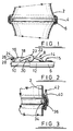
- the assembly comprises a hollow sleeve 2 formed of a gas permeable filter fabric.
- a circular reinforcing support ring member 4 of circular cross-section is clamped inside the sleeve by means of an exterior clamping member 6 of channel-shaped cross-section which engages the interior support ring member, gripping the sleeve and securely locating the ring member in place.
- the filter fabric from which the sleeve is formed in the present example comprises a woven glass fibre supporting fabric having laminated to the inside thereof a thin permeable membrane formed of expanded PTFE (available under the Registered Trademark GORE-TEX) which contains minute pores sufficient to remove solid particulate matter of particle size down to sub-micron levels.
- expanded PTFE available under the Registered Trademark GORE-TEX
- the expanded PTFE membrane tends to retain solid particles at the surface thereof, which facilitates later removal of the collected solid material.
- PTFE has excellent temperature and chemical resistance properties.
- the interior support ring member 4 is usually formed of stainless steel and acts to hold the sleeve open, particularly during reverse airflow cleaning operations.
- the channel-shaped clamping member 6 is also formed of stainless steel to minimise any differential expansion effects.
- the clamping member might be formed of a metal having a slightly lower coefficient of expansion so that rise in temperature would tend to tighten the clamping member around the ring.
- the filter sleeve would be approximately 10 metres in length and be provided with interior support ring members clamped in place at approximately 1 metre intervals along its length.
- FIG. 2 shows a typical bandclip 8 for tightening the exterior clamping member 6 around the interior support ring member 4.
- the clamping member 6 has two overlapping relatively slideable ends 10, 12.
- a pair of spaced hooks 14, 15 are provided on end 12 and attached thereto, e.g. by means of rivets.
- An overcentre clip mechanism 16 is attached to the other end 10.
- the clip comprises a body 18 pivotally attached to the end 10 at pivot point 20 via a base member.
- a loop 22 having a centre section 23 in the form of a spring coil is pivotally attached at one end to the body 18 and at the other end hooks over the hook 14 or 15 thereby securing together the two ends of the clamping member.
- the clip is secured in the locked position by means of a self tapping screw 24 which passes through a hole in extension 26 of the body and is screwed into a threaded hole in an inclined strap 28 which is formed as an extension of the baseplate.
- Figure 3 shows a second embodiment wherein the support ring member 34 is of oval cross-section to maximise the clamping area for a given weight of ring.
- Clamping member 36 has a complementary channel section. The oval section reduces the angle of contact of the sleeve material when the sleeve is deflated during back-pressure cleaning operations, and helps minimise the chance of damage to the filter sleeve.
- a felt layer 40 formed of PTFE, which helps protect the filter sleeve from abrasion or cutting by the clamping member.
- the felt passes around the clamping member and the bandclip so as to enclose them, and the two edges are sewn together along a seam 42. Enclosing the clamping member and bandclip in this way helps to prevent damage to adjacent filter sleeves during installation.
- the reinforced sleeve assembly may be made up as follows.
- the hollow sleeve of filter material is stretched out and positions for the support ring members are marked on the outside thereof.
- the rings are inserted one at a time and a layer of cushioning felt placed around the ring on the outside of the sleeve.
- a clamping member is then clamped around the exterior thereof, care being taken that the rings are secured in place at right angles to the length of the hollow sleeve.
- the bandclip is disconnected and the ends of the clamping member pulled apart slightly to enable the clamping member to be slipped around the support ring.
- the ends are then drawn together and loop 22 is hooked over hook 14.
- the body is pivoted downwards to reach the position shown in Figure 2.
- the filter is operated as follows. Particle-laden gas is passed into the inside of the sleeve through the bottom end, the top being closed. Cleaned air passes through the sleeve, whilst the solid particles are retained on the inside of the sleeve.
- the filter is cleaned by applying a partial suction to the inside of the sleeve to draw air backwards through the sleeve. This partly collapses the sleeve causing the solid particles to become dislodged and to fall down the centre of the sleeve to be collected.
- the interior support ring members 4 prevent total collapse of the sleeve, always leaving a central airflow space along the entire length of the filter sleeve.
Landscapes
- Chemical & Material Sciences (AREA)
- Chemical Kinetics & Catalysis (AREA)
- Inorganic Chemistry (AREA)
- Springs (AREA)
- Filtering Of Dispersed Particles In Gases (AREA)
- Moulding By Coating Moulds (AREA)
- Laminated Bodies (AREA)
- Filtering Materials (AREA)
- Separation Using Semi-Permeable Membranes (AREA)
- Rigid Pipes And Flexible Pipes (AREA)
Abstract
Description
- The present invention relates to a reinforced sleeve assembly, particularly but not exclusively for use in gas filtration.
- Recent environmental legislation places increasingly severe limits on the permitted level of particulate material (such as soot, fume and dust particles) which may be emitted with gases vented to the atmosphere. A typical maximum permitted solids content is 250mg per cubic metre of air, though in some countries lower limits such as 100mg per cubic metre are prescribed. However, there is a need to be able to meet increasingly stringent emission standards.
- In order to remove particles from the gas, installations such as power stations, manufacturing plants, incinerators etc. are fitted with bag filters which filter out and collect the solid material. One particular construction employs filter cloth formed into tubular vertical sleeves. Gas to be filtered is then passed through the sleeves either from the inside or the outside. Solid material collected on the filter bags may be periodically removed by mechanical shaking or by applying back pressure to the sleeves to dislodge the material, which falls and is collected up. In one particular type of filter, gas to be filtered is passed up inside the filter sleeve. When solid material builds up on the filter, it is cleaned by either applying a reverse pressure of cleaning air to the outside of the sleeve or by applying a reduced pressure to the inside of the sleeve such as to partially collapse the sleeve and cause the solid matter to become dislodged. However, it is important that the sleeve should not be allowed to collapse completely and thereby prevent airflow and removal of solids. To prevent collapse of the sleeve, rings are sewn around the outside of the filter sleeve at regular intervals along its length. Typically, such filters are 5 to 12 metres in length and have rings sewn in at approximately 1 metre intervals.
- The gases to be filtered are often at relatively high temperatures e.g. 150 to 300°c and may contain corrosive gases such as sulphur oxides and nitrogen oxides. The material used to construct the filter sleeve must therefore be chosen to withstand the conditions encountered. A particularly suitable material is an expanded polytetrafluoroethylene (PTFE) material available under the Registered Trademark GORE-TEX. Expansion of the material results in a very small pore size able to filter out particles of sub-micron size. Also, PTFE is able to withstand high temperatures and corrosive gases. Usually, the PTFE filter will be supported on a woven or non-woven support material.
- However, whilst the PTFE filter material itself is capable of excluding almost all particles, a limit is imposed on the efficiency of the overall filter by the fact that the supporting rings are sewn in place. The holes made by the sewing process gradually become enlarged due to the tension on the filter cloth and the pulling and cutting action of the sewing thread. This leads to relatively large holes which allow small particles to escape and also constitute points of weakness in the filter leading to mechanical failure.
- Reinforced sleeve assemblies wich comprise
- a hollow sleeve formed of a non-rigid sheet material;
- a rigid interior support ring member arranged around the inside of the sleeve; and
- an exterior clamping member clamped around the outside of the sleeve are known from US-A- 3 243 940 or US-A- 3 241 297.
- It is an object of the present invention to improve the securing of the supporting rings to the hollow filter sleeve.
- The present invention provides a reinforced sleeve assembly of the kind mentioned just above, particularly for use in gas filtration, which is characterized in that the exterior clamping member has a cross-section which includes a channel-shaped cross-sectional position operatively embracing the interior support ring such that the members grip the sleeve and are securely located thereon.
- The hollow sleeve may be formed of any woven or non-woven material suitable for the application in mind. Whilst the present invention is primarily intended for use in the filtration field, it may also find general application where a sleeve of non-rigid material is to be held open, such as in a chute. For filtration applications, the material is preferably a gas-permeable filtration membrane, such as an expanded fluorocarbon polymer especially PTFE. In order to provide structural strength, the filter membrane may be supported, for example, by lamination or direct deposition, on a woven or non-woven substrate formed for example, from glass fibre, stainless steel or a polymer (such as a fluorocarbon polymer, a polyester, a polyamide, or polypropylene) or from carbon fibre. The particular substrate material will generally be chosen depending on the temperature and corrosiveness of the gas to be filtered. Polymer substrate materials may include fillers, such as carbon for imparting antistatic properties.
- The rigid interior support ring member is generally of a circular or oval shape, and is typically formed from an inert metal such as stainless steel.
- The exterior clamping member is generally of the same shape as the ring member and formed of the same material to avoid stresses being set up by differential thermal expansion.
- The support ring member and clamping member have inter-engagable cross-sectional configurations such that when the clamping member is clamped around the support ring they become locked together. In one embodiment, the ring is of circular cross-section and the clamping member has a channel cross-section; or vice versa. In another embodiment, both have inter-engagable channel-shaped cross-sections.
- In order to increase the clamping area, a pair of circular cross-section rings may be used side-by-side; though this makes assembly a little more difficult. However, in a preferred embodiment, the interior ring has an oval cross-section (with the long axis of the oval along the line of the hollow sleeve) and the clamping member has a corresponding oval shaped channel. This oval cross-section provides a large clamping contact area and also reduces the angle through which the sleeve material is bent; both of which help to avoid damage to the sleeve material.
- The exterior clamping member is generally of variable peripheral length so that it can be tightened around the support ring. Thus, the clamping member may be provided with a screw clip or band clip for tightening the clamping member. However, many suitable ways of tightening the clamping member are known in the art.
- In order to prevent creases being set up in the filter sleeve, which could lead to premature failure, it is important that the member should be securely clamped in place, usually at right angles to the length of the hollow sleeve. In order to prevent chaffing of the filter material, it may be desirable to interpose sheets of polymeric material between the members and the filter sleeve.
- The reinforced sleeve assembly is particularly useful for providing high performance filters, particularly when used in conjunction with expanded PTFE filter membranes and eliminates stitching holes around the support rings. Such filters may be used for removing micron sized particles from flue gas from coal-fired boilers, prior to the gas being passed to catalytic convertors for removing sulphur oxides and nitrogen oxides. Such particles would otherwise tend to deactivate the catalyst materials.
- Embodiments of the present invention will now be described by way of example only with reference to the drawings wherein
- Figure 1 is a cross-sectional view of part of a reinforced sleeve assembly for gas filtration;
- Figure 2 is a side elevation of a bandclip for tightening the exterior clamping member; and
- Figure 3 is a partial section of a further embodiment wherein the support ring is of oval cross-section.
- As shown in Figure 1, the assembly comprises a
hollow sleeve 2 formed of a gas permeable filter fabric. A circular reinforcingsupport ring member 4 of circular cross-section is clamped inside the sleeve by means of anexterior clamping member 6 of channel-shaped cross-section which engages the interior support ring member, gripping the sleeve and securely locating the ring member in place. - The filter fabric from which the sleeve is formed in the present example comprises a woven glass fibre supporting fabric having laminated to the inside thereof a thin permeable membrane formed of expanded PTFE (available under the Registered Trademark GORE-TEX) which contains minute pores sufficient to remove solid particulate matter of particle size down to sub-micron levels. In contrast to other filter fabrics, the expanded PTFE membrane tends to retain solid particles at the surface thereof, which facilitates later removal of the collected solid material. Moreover, PTFE has excellent temperature and chemical resistance properties.
- The interior
support ring member 4 is usually formed of stainless steel and acts to hold the sleeve open, particularly during reverse airflow cleaning operations. The channel-shaped clamping member 6 is also formed of stainless steel to minimise any differential expansion effects. Alternatively, the clamping member might be formed of a metal having a slightly lower coefficient of expansion so that rise in temperature would tend to tighten the clamping member around the ring. Generally, the filter sleeve would be approximately 10 metres in length and be provided with interior support ring members clamped in place at approximately 1 metre intervals along its length. - Figure 2 shows a
typical bandclip 8 for tightening theexterior clamping member 6 around the interiorsupport ring member 4. However, many alternative ways of tightening the clamping member will be apparent to the skilled man. The clampingmember 6 has two overlapping relatively slideable ends 10, 12. A pair of spaced hooks 14, 15 are provided onend 12 and attached thereto, e.g. by means of rivets. Anovercentre clip mechanism 16 is attached to theother end 10. The clip comprises abody 18 pivotally attached to theend 10 atpivot point 20 via a base member. Aloop 22 having acentre section 23 in the form of a spring coil is pivotally attached at one end to thebody 18 and at the other end hooks over thehook self tapping screw 24 which passes through a hole inextension 26 of the body and is screwed into a threaded hole in aninclined strap 28 which is formed as an extension of the baseplate. - Figure 3 shows a second embodiment wherein the
support ring member 34 is of oval cross-section to maximise the clamping area for a given weight of ring. Clampingmember 36 has a complementary channel section. The oval section reduces the angle of contact of the sleeve material when the sleeve is deflated during back-pressure cleaning operations, and helps minimise the chance of damage to the filter sleeve. - Interposed between the oval
support ring member 34 and the clampingmember 36 is a feltlayer 40 formed of PTFE, which helps protect the filter sleeve from abrasion or cutting by the clamping member. The felt passes around the clamping member and the bandclip so as to enclose them, and the two edges are sewn together along aseam 42. Enclosing the clamping member and bandclip in this way helps to prevent damage to adjacent filter sleeves during installation. - The reinforced sleeve assembly may be made up as follows. The hollow sleeve of filter material is stretched out and positions for the support ring members are marked on the outside thereof. Then, the rings are inserted one at a time and a layer of cushioning felt placed around the ring on the outside of the sleeve. A clamping member is then clamped around the exterior thereof, care being taken that the rings are secured in place at right angles to the length of the hollow sleeve. To locate the clamping member, the bandclip is disconnected and the ends of the clamping member pulled apart slightly to enable the clamping member to be slipped around the support ring. The ends are then drawn together and
loop 22 is hooked overhook 14. The body is pivoted downwards to reach the position shown in Figure 2. The longitudinal tension on the hollow filter sleeve is relaxed once all the rings have been clamped in place, and the sleeve adopts the relaxed position as shown in Figure 1. As the material clamped between the ring and the clamping member relaxes, the radially-outward pressure exerted by the sleeve material on the clamping member also reduces so that a degree of play may arise. This can be taken up by undoing the bandclip, tightening the loop further and hooking it over therear hook 15. Thescrew 24 is then screwed (or rivetted) to strap 28 to hold the clip in its locked position. - The filter is operated as follows. Particle-laden gas is passed into the inside of the sleeve through the bottom end, the top being closed. Cleaned air passes through the sleeve, whilst the solid particles are retained on the inside of the sleeve. When the pressure drop across the filter rises to a predetermined level, the filter is cleaned by applying a partial suction to the inside of the sleeve to draw air backwards through the sleeve. This partly collapses the sleeve causing the solid particles to become dislodged and to fall down the centre of the sleeve to be collected. The interior
support ring members 4 prevent total collapse of the sleeve, always leaving a central airflow space along the entire length of the filter sleeve.
Claims (7)
- A reinforced sleeve assembly, particularly for use in gas filtration, which comprises:
a hollow sleeve (2) formed of a non-rigid sheet material;
a rigid interior support ring member (4, 34) arranged around the inside of the sleeve; and
an exterior clamping member (6, 36) clamped around the outside of the sleeve,
characterized in that the exterior clamping member has a cross-section which includes a channel-shaped cross-sectional portion operatively embracing the interior support ring such that the members grip the sleeve and are securely located thereon. - An assembly according to claim 1 wherein the sleeve material comprises a film of porous expanded polytetrafluoroethylene.
- An assembly according to claim 2 wherein the porous expanded polytetrafluoroethylene film is laminated to a substrate material.
- An assembly according to any preceding claim wherein the support ring member (34) is of oval cross-section.
- An assembly according to any of claims 1 to 3 which comprises a pair of support ring members each of circular cross-section arranged side-by-side.
- An assembly according to any preceding claim wherein the exterior clamping member is circumferentially discontinuous and is provided with clip means (8) for tightening the clamping member around the interior ring member.
- A filter assembly which comprises a reinforced sleeve assembly according to any preceding claim, means for introducing a stream of gas to be cleaned into the interior of the sleeve assembly, and means for providing a backpressure across the sleeve assembly so as to dislodge matter filtered from the gas stream.
Applications Claiming Priority (2)
| Application Number | Priority Date | Filing Date | Title |
|---|---|---|---|
| GB909008559A GB9008559D0 (en) | 1990-04-17 | 1990-04-17 | Reinforced sleeve assembly |
| GB9008559 | 1990-04-17 |
Publications (2)
| Publication Number | Publication Date |
|---|---|
| EP0453156A1 EP0453156A1 (en) | 1991-10-23 |
| EP0453156B1 true EP0453156B1 (en) | 1994-12-14 |
Family
ID=10674496
Family Applications (1)
| Application Number | Title | Priority Date | Filing Date |
|---|---|---|---|
| EP91303124A Expired - Lifetime EP0453156B1 (en) | 1990-04-17 | 1991-04-09 | Reinforced sleeve assembly |
Country Status (7)
| Country | Link |
|---|---|
| EP (1) | EP0453156B1 (en) |
| JP (1) | JPH0584410A (en) |
| AT (1) | ATE115433T1 (en) |
| DE (1) | DE69105802T2 (en) |
| DK (1) | DK0453156T3 (en) |
| GB (2) | GB9008559D0 (en) |
| NO (1) | NO178141C (en) |
Families Citing this family (2)
| Publication number | Priority date | Publication date | Assignee | Title |
|---|---|---|---|---|
| JP2007105655A (en) * | 2005-10-14 | 2007-04-26 | Nakao Filter Kogyo Kk | Bag filter and dust collection method using it |
| US7837756B2 (en) | 2007-04-05 | 2010-11-23 | Aaf-Mcquay Inc. | Filter with ePTFE and method of forming |
Family Cites Families (10)
| Publication number | Priority date | Publication date | Assignee | Title |
|---|---|---|---|---|
| US3243940A (en) * | 1961-10-13 | 1966-04-05 | Phillips Petroleum Co | Bag filtering process and apparatus |
| US3241297A (en) * | 1962-04-13 | 1966-03-22 | Phillips Petroleum Co | Bag filtering apparatus |
| FR1536888A (en) * | 1967-09-13 | 1968-08-16 | Flexible filter candle | |
| US3486626A (en) * | 1968-02-01 | 1969-12-30 | Sam Close | Replaceable medium,extended area filter unit |
| US3538687A (en) * | 1968-07-12 | 1970-11-10 | Aerodyne Machinery Corp | Device for filtering solids from a gas |
| US4244718A (en) * | 1976-04-15 | 1981-01-13 | Albany International Corp. | Reverse gas-flow bag filter |
| US4276069A (en) * | 1979-09-12 | 1981-06-30 | American Air Filter Company, Inc. | Filter arrangement |
| GB2064978B (en) * | 1979-12-07 | 1983-05-25 | Clarkes Sheet Metal | Filter bag with removable shaping members |
| US4398931A (en) * | 1982-05-19 | 1983-08-16 | Minnesota Mining And Manufacturing Company | Ceramic fabric filter |
| DK142384A (en) * | 1984-02-29 | 1985-08-30 | Schmidt & Jessen A S | SIGNING BASKET WITH AT LEAST ONE PUT FORM AND AT BOTH END END OPEN SIGNS |
-
1990
- 1990-04-17 GB GB909008559A patent/GB9008559D0/en active Pending
-
1991
- 1991-04-09 EP EP91303124A patent/EP0453156B1/en not_active Expired - Lifetime
- 1991-04-09 GB GB9107440A patent/GB2243091B/en not_active Expired - Lifetime
- 1991-04-09 AT AT91303124T patent/ATE115433T1/en not_active IP Right Cessation
- 1991-04-09 DE DE69105802T patent/DE69105802T2/en not_active Expired - Fee Related
- 1991-04-09 DK DK91303124.1T patent/DK0453156T3/en active
- 1991-04-15 JP JP3082515A patent/JPH0584410A/en active Pending
- 1991-04-16 NO NO911494A patent/NO178141C/en unknown
Also Published As
| Publication number | Publication date |
|---|---|
| DK0453156T3 (en) | 1995-02-20 |
| NO178141B (en) | 1995-10-23 |
| GB2243091A (en) | 1991-10-23 |
| EP0453156A1 (en) | 1991-10-23 |
| DE69105802D1 (en) | 1995-01-26 |
| GB9008559D0 (en) | 1990-06-13 |
| ATE115433T1 (en) | 1994-12-15 |
| GB2243091B (en) | 1993-12-08 |
| JPH0584410A (en) | 1993-04-06 |
| NO911494D0 (en) | 1991-04-16 |
| GB9107440D0 (en) | 1991-05-22 |
| NO178141C (en) | 1996-01-31 |
| NO911494L (en) | 1991-10-18 |
| DE69105802T2 (en) | 1995-08-03 |
Similar Documents
| Publication | Publication Date | Title |
|---|---|---|
| EP0095297B1 (en) | Ceramic fabric filter | |
| CA2071295C (en) | Integrated molded collar, filter bag, cage and locking ring assembly for baghouses | |
| KR101196282B1 (en) | Turbine air-intake filter | |
| KR102916913B1 (en) | Filter bags comprising a porous membrane | |
| US6375698B1 (en) | Long filter assembly with connection device | |
| US7964007B2 (en) | Filter bag for use in dust collector | |
| US4424070A (en) | Dust collecting filter cartridge and attachment structure for suspending same from baghouse tube sheet | |
| CN102711951B (en) | filter | |
| JP2003509246A (en) | Chemically active filter material | |
| US4531957A (en) | Filtering material and filtration apparatus employing the filtering material | |
| US4149863A (en) | Bag filter apparatus | |
| US4256473A (en) | Filter bag attaching means | |
| US6017379A (en) | Cartridge filter | |
| EP0399249A1 (en) | Device at a filter hose | |
| EP0453156A1 (en) | Reinforced sleeve assembly | |
| GB1573023A (en) | Tubular gas filter | |
| US3429107A (en) | Filter bag with attached encircling ring | |
| US8333826B2 (en) | Pleatable PTFE filter media with ePTFE membrane | |
| US3966434A (en) | Method for filtering gas and cleaning of filter bags | |
| KR101522090B1 (en) | Filter bag having strap rino and fixing device thereof | |
| JP2016030252A (en) | Filter-cloth for bag filter, and replacing method for the filter-cloth for bag filter | |
| US4512789A (en) | Filter bag clamp | |
| JP2007105655A (en) | Bag filter and dust collection method using it | |
| TWM657253U (en) | Improved structure of backwash dust collection bag | |
| WO2006112985A1 (en) | Two-piece filter bag |
Legal Events
| Date | Code | Title | Description |
|---|---|---|---|
| PUAI | Public reference made under article 153(3) epc to a published international application that has entered the european phase |
Free format text: ORIGINAL CODE: 0009012 |
|
| AK | Designated contracting states |
Kind code of ref document: A1 Designated state(s): AT BE DE DK FR GB IT NL SE |
|
| 17P | Request for examination filed |
Effective date: 19920401 |
|
| 17Q | First examination report despatched |
Effective date: 19930922 |
|
| GRAA | (expected) grant |
Free format text: ORIGINAL CODE: 0009210 |
|
| AK | Designated contracting states |
Kind code of ref document: B1 Designated state(s): AT BE DE DK FR GB IT NL SE |
|
| PG25 | Lapsed in a contracting state [announced via postgrant information from national office to epo] |
Ref country code: NL Effective date: 19941214 Ref country code: BE Effective date: 19941214 Ref country code: AT Effective date: 19941214 |
|
| REF | Corresponds to: |
Ref document number: 115433 Country of ref document: AT Date of ref document: 19941215 Kind code of ref document: T |
|
| ITF | It: translation for a ep patent filed | ||
| REF | Corresponds to: |
Ref document number: 69105802 Country of ref document: DE Date of ref document: 19950126 |
|
| REG | Reference to a national code |
Ref country code: DK Ref legal event code: T3 |
|
| ET | Fr: translation filed | ||
| PGFP | Annual fee paid to national office [announced via postgrant information from national office to epo] |
Ref country code: BE Payment date: 19950316 Year of fee payment: 5 |
|
| NLV1 | Nl: lapsed or annulled due to failure to fulfill the requirements of art. 29p and 29m of the patents act | ||
| PLBE | No opposition filed within time limit |
Free format text: ORIGINAL CODE: 0009261 |
|
| STAA | Information on the status of an ep patent application or granted ep patent |
Free format text: STATUS: NO OPPOSITION FILED WITHIN TIME LIMIT |
|
| 26N | No opposition filed | ||
| PGFP | Annual fee paid to national office [announced via postgrant information from national office to epo] |
Ref country code: FR Payment date: 19990317 Year of fee payment: 9 |
|
| PGFP | Annual fee paid to national office [announced via postgrant information from national office to epo] |
Ref country code: SE Payment date: 19990318 Year of fee payment: 9 Ref country code: GB Payment date: 19990318 Year of fee payment: 9 Ref country code: DE Payment date: 19990318 Year of fee payment: 9 |
|
| PGFP | Annual fee paid to national office [announced via postgrant information from national office to epo] |
Ref country code: DK Payment date: 19990319 Year of fee payment: 9 |
|
| PG25 | Lapsed in a contracting state [announced via postgrant information from national office to epo] |
Ref country code: GB Free format text: LAPSE BECAUSE OF NON-PAYMENT OF DUE FEES Effective date: 20000409 Ref country code: DK Free format text: LAPSE BECAUSE OF NON-PAYMENT OF DUE FEES Effective date: 20000409 |
|
| PG25 | Lapsed in a contracting state [announced via postgrant information from national office to epo] |
Ref country code: SE Free format text: LAPSE BECAUSE OF NON-PAYMENT OF DUE FEES Effective date: 20000410 |
|
| GBPC | Gb: european patent ceased through non-payment of renewal fee |
Effective date: 20000409 |
|
| EUG | Se: european patent has lapsed |
Ref document number: 91303124.1 |
|
| PG25 | Lapsed in a contracting state [announced via postgrant information from national office to epo] |
Ref country code: FR Free format text: LAPSE BECAUSE OF NON-PAYMENT OF DUE FEES Effective date: 20001229 |
|
| REG | Reference to a national code |
Ref country code: DK Ref legal event code: EBP |
|
| PG25 | Lapsed in a contracting state [announced via postgrant information from national office to epo] |
Ref country code: DE Free format text: LAPSE BECAUSE OF NON-PAYMENT OF DUE FEES Effective date: 20010201 |
|
| REG | Reference to a national code |
Ref country code: FR Ref legal event code: ST |
|
| PG25 | Lapsed in a contracting state [announced via postgrant information from national office to epo] |
Ref country code: IT Free format text: LAPSE BECAUSE OF NON-PAYMENT OF DUE FEES Effective date: 20050409 |