EP0452844A1 - Method for freezing food products in containers, and an automatic plate freezer for implementing the method - Google Patents
Method for freezing food products in containers, and an automatic plate freezer for implementing the method Download PDFInfo
- Publication number
- EP0452844A1 EP0452844A1 EP91105961A EP91105961A EP0452844A1 EP 0452844 A1 EP0452844 A1 EP 0452844A1 EP 91105961 A EP91105961 A EP 91105961A EP 91105961 A EP91105961 A EP 91105961A EP 0452844 A1 EP0452844 A1 EP 0452844A1
- Authority
- EP
- European Patent Office
- Prior art keywords
- plate
- containers
- freezer
- air
- plates
- Prior art date
- Legal status (The legal status is an assumption and is not a legal conclusion. Google has not performed a legal analysis and makes no representation as to the accuracy of the status listed.)
- Granted
Links
Images

Classifications
-
- F—MECHANICAL ENGINEERING; LIGHTING; HEATING; WEAPONS; BLASTING
- F25—REFRIGERATION OR COOLING; COMBINED HEATING AND REFRIGERATION SYSTEMS; HEAT PUMP SYSTEMS; MANUFACTURE OR STORAGE OF ICE; LIQUEFACTION SOLIDIFICATION OF GASES
- F25D—REFRIGERATORS; COLD ROOMS; ICE-BOXES; COOLING OR FREEZING APPARATUS NOT OTHERWISE PROVIDED FOR
- F25D13/00—Stationary devices, e.g. cold-rooms
- F25D13/06—Stationary devices, e.g. cold-rooms with conveyors carrying articles to be cooled through the cooling space
- F25D13/067—Stationary devices, e.g. cold-rooms with conveyors carrying articles to be cooled through the cooling space with circulation of gaseous cooling fluid
-
- A—HUMAN NECESSITIES
- A23—FOODS OR FOODSTUFFS; TREATMENT THEREOF, NOT COVERED BY OTHER CLASSES
- A23L—FOODS, FOODSTUFFS, OR NON-ALCOHOLIC BEVERAGES, NOT COVERED BY SUBCLASSES A21D OR A23B-A23J; THEIR PREPARATION OR TREATMENT, e.g. COOKING, MODIFICATION OF NUTRITIVE QUALITIES, PHYSICAL TREATMENT; PRESERVATION OF FOODS OR FOODSTUFFS, IN GENERAL
- A23L3/00—Preservation of foods or foodstuffs, in general, e.g. pasteurising, sterilising, specially adapted for foods or foodstuffs
- A23L3/36—Freezing; Subsequent thawing; Cooling
- A23L3/361—Freezing; Subsequent thawing; Cooling the materials being transported through or in the apparatus, with or without shaping, e.g. in form of powder, granules, or flakes
- A23L3/362—Freezing; Subsequent thawing; Cooling the materials being transported through or in the apparatus, with or without shaping, e.g. in form of powder, granules, or flakes with packages or with shaping in form of blocks or portions
-
- F—MECHANICAL ENGINEERING; LIGHTING; HEATING; WEAPONS; BLASTING
- F25—REFRIGERATION OR COOLING; COMBINED HEATING AND REFRIGERATION SYSTEMS; HEAT PUMP SYSTEMS; MANUFACTURE OR STORAGE OF ICE; LIQUEFACTION SOLIDIFICATION OF GASES
- F25D—REFRIGERATORS; COLD ROOMS; ICE-BOXES; COOLING OR FREEZING APPARATUS NOT OTHERWISE PROVIDED FOR
- F25D31/00—Other cooling or freezing apparatus
- F25D31/001—Plate freezers
Definitions
- This invention relates to a method for freezing food products packaged in boxes, trays, dishes, bags and the like, and to an automatic plate freezer for implementing the method.
- Food products for freezing can be considered to form part of two large groups.
- the first group comprises those products which are frozen in parallelepiped containers having such a consistency or strength as to withstand the mechanical stresses to which they are subjected during their insertion and movement within the freezer.
- the second group comprises those products which are frozen after being packaged in bags or in trays of low mechanical strength or of non-parallelepiped shape such as trays with their side walls diverging outwards from their base.
- the products of the first group are frozen in automatic plate freezers, ie of the type comprising a plurality of superposed spaced-apart Plates through which a refrigerant fluid circulates.
- the products to be frozen, enclosed in their respective strong parallelepiped containers and arriving from a conveyor belt, are loaded onto a plate positioned in a loading station and spaced apart from the immediately overlying plate.
- a number of such containers are loaded simultaneously side by side to form a row substantially equal to the plate width.
- the containers of this second row rest against the containers of the first row and push them forward. This is repeated until the plate is completely loaded, during which a large number of rows move along the plate, each row being pushed forward by the next row and itself pushing the previous row forward.
- such containers are currently frozen on a different type of freezer, ie they are loaded onto an endless conveyor belt driven within a large refrigerated compartment in which fans blow very cold air over the containers until the products contained in them are frozen.
- These types of freezers have very low efficiency and the time required for freezing the food products is excessively long, with the result that the freezer volume must be excessively large.
- plate freezers The efficiency of plate freezers is much higher than that of the aforesaid cold air freezers, and because of this plate freezers are in fact also used for products enclosed in boxes of low mechanical strength or in bags, dishes, trays or the like of non-parallelepiped shape.
- each row of containers (originating from a conveyor belt) is pushed forward onto the plate by an automatic pusher substantially consisting of a long transverse bar which rests against the upstream side of all the containers of the considered row and pushes them forward onto the freezer plate.
- the next container row is pushed onto the plate by another pusher identical to the first and which simultaneously pushes the first pusher forward along the plate together with the first container row.
- a plurality of container rows builds up on the plate, each row being moved forward along the plate by a respective pusher (possibly shaped to accommodate the container shape), so that a plurality of pushers in also present on the plate.
- Plate freezers are well known and various types are described in the patents US-A-2,882,697, US-A-3,271,973, US-A-4,240,270, US-A-4,423,604, US-A-4,432,214, GB-A-2,041,313, GB-A-2,120,776 and FR-A-2,531,552.
- plate freezers have the highest efficiency but have considerable drawbacks when used for freezing food products enclosed in boxes of low mechanical strength, in bags, or in dishes or trays of non-parallelepiped shape, and in particular with side walls which diverge upwards from the tray base.
- these drawbacks are due to the fact a large number of pushers together with complicated automatic systems for returning the pushers leaving tile discharge station to the loading station are required, or supplementary frames with seats for housing the containers.
- the main object of the present invention is to provide an automatic plate freezer for deep-freezing food products packaged in boxes, bags or trays of any shape but with a flat base, the freezer being of reliable and simple operation, of relatively simple and compact structure, and allowing effective freezing of food products without damage to the containers in which they are enclosed.
- jets of dehumidified cold air are fed under the base of the containers located on the plate positioned in the container loading station to lift the containers from the plate surface.
- the automatic plate freezer for implementing the aforesaid method is characterised by comprising means for cooling and dehumidifying the air present within the freezer and for maintaining it at low temperature and dehumidified, and means for generating and maintaining a cold dehumidified air stream between the plates within the freezer.
- the plates of the automatic freezer preferably comprise a plurality of channels in which holes are provided opening into the upper surface of each plate, means being provided for feeding cold dehumidified air into said channels of that plate positioned at the loading station for the products to be frozen in the freezer.
- Figures 1 to 4 show an automatic freezer comprising an insulated housing 1, described hereinafter, containing a plurality of refrigeration plates 19, also described hereinafter and shown in detail in Figures 5, 6 and 7 and devices for moving them and positioning them one at a time at the correct level in a loading station to be loaded with or unloaded of packages or containers enclosing the food products to be frozen, these devices not being described nor shown on the drawings as they comprise the normal frames, hydraulic cylinders and other parts used in this type of freezer and illustrated in the previous patents cited in the introduction to the present description.
- the freezer also comprises a loading device 2 for the packages or containers 22, which is also of well known type and commonly used in such freezers, for example of the types described in the patents US-A-3,557,975 and GB-B-1,259,073, with the difference that in the case of the present invention it is totally ducted and isolated from the outside environment.
- a conveyor belt 6 for the packages arriving at the housing 1 and a conveyor belt 7 for the packages leaving at the housing 1 are provided at the front and rear of the freezer respectively, those belts having that portion close to the the housing enclosed within ducts 3 and 4 which are connected together by a channel 5 to isolate the areas in which the packages are introduced into the housing 1 and discharged from it, so that the only apertures through which air can enter and leave are the apertures 3a and 4a, which have cross-sections just greater than that of the packages 22, these apertures being provided with closure devices of known structure, which are normally closed and open only when the packages have to pass through them.
- a self-contained unit 8 is shown schematically for refrigerating and dehumidifying the air contained in the housing 1 and in the ducts 3 and 4 connected to it, the refrigeration unit 8 being connected to the housing 1 by connectors and ducting 9 and 10 and being connected to the ducts 3 and 4 by means of the connection branch 11.
- the purpose of the unit 8 is to cool to a temperature similar to that of the refrigeration plates 19 and to continuously dehumidify both the air present within the freezer and the air which enters through the ducts 3 and 4 together with the product to be frozen. or from other sources.
- the refrigeration and dehumidification unit 8 is put into operation before operating the freezer, ie before feeding the refrigerant fluid into the plates, in order to prevent frost forming or, them, the unit also circulating the cold dehumidified air within the freezer so that it aids heat transfer with the product to be frozen.
- a device 12 is provided to cool and dehumidify air withdrawn from the interior of the housing 1 (instead, but less advantageously, the air fed by the device 12 could be taken from the compressed air main of the factory in which the freezer operates), compress it, remove any traces of impurities and feed it to a device described hereinafter and shown in Figure 8, which then feeds it to the plate 19 which is at rest in the position for loading, and only to that plate.
- This air traverses channels provided in each plate but separate from those through which the refrigerant fluid circulates, to feed the holes provided in the upper surface of each plate, through which the air is expelled in the form of jets which create air cushions able to lift the packages of products to be frozen and allow them to be moved by the loading device 2 under zero or nearly zero friction conditions.
- a fundamental characteristic of the described freezer is that it operates under zero humidity conditions within the housing 1, and thus with the plates cold but dry, without frost, and with heat transfer of mixed type, ie by direct contact between the packages and plates and by conduction to the cold air circulating within the housing 1.
- the freezer is suitable for freezing food products enclosed in parallelepiped packages (freezing improved by the absence of frost on the plates, ie by improved contact between the plates and packages) and products enclosed in trays either of non-parallelepiped shape or of low mechanical strength (it allowing these latter to be loaded, as loading is facilitated by the absence of friction and of adhesion with the plate, which if present result in forces which usually cause deformation of the packages when they are pushed in order to move along the plates).
- the housing 1 of the freezer according to the present invention is shown in vertical section in Figure 3 and in horizontal section in Figure 4.
- the front end wall 1a and the rear end wall 1b are both provided with inner backing walls 13a and 13b respectively, which form a front interspace 1c and a rear interspace 1d.
- the two interspaces are divided into two parts by the product entry mouth 14 and product exit mouth 15, namely an upper part and a lower part, which are connected together by lateral ducts 16 and 17 respectively.
- the backing Walls 13a, 13b are provided with holes suitably distributed over their entire surface, through which a number of small air jets pass, these being indicated by small curved arrows in Figure 3.
- the interspace 1c is connected to the air refrigeration and dehumidification unit 8 by the ducts 9, the interspace 1d being connected to the same unit by the ducts 18 and 10.
- the housing 1 houses a certain number of plates 19 in a superposed arrangement spaced apart by spacers of adequate height for the product to be frozen, with refrigerant fluid circulating through each plate, and means for raising the plates, lowering them, moving them to the level of the mouths 14 and 15, spacing them apart for the introduction of the product to be frozen, and making them approach each other again after the product has been loaded, which means will, as stated, not be described as they are of usual type and amply described in detail in the previous patents cited in the introduction to the present description.
- the loading device 2 (which as stated is totally housed and isolated from the outside) is located outside the housing 1, and is of the type usually used in such freezers (see for example the patents USA-A-3,557,975, USA-A-4,432,214, GB-B-1,259,073 etc.) but of which the drawings show only the loading bar 20 and a small portion of the chains 21 which move the bar 20 forwards and backwards.
- the purpose of the loading device is to transfer a row of packages 22, carried by the belt 6 and abutting against the stop element 23 ( Figure 4) onto the plate 19 at rest in front of the loading mouth 14.
- the unit 8 is able to circulate the air which it has previously dehumidified and cooled to a temperature similar to that of the plates 19, by feeding it through the channels 9 into the lower part of the interspace 1c and from here into the upper part of the interspace 1c via the lateral channels 16, and to draw said air from the lower and upper parts of the interspace 14, connected together by the lateral channels 17, via return channels 18 and 10 which again feed it to said unit 8.
- the air is obliged to pass through the housing 1 and, in the region in which the plates 19 are located, to infiltrate between them and into the spaces left free by the packages 22, which air being at a temperature similar to the plates participates in the cooling of the product, to provide the same effect as that due to direct contact between the packages and the plates.
- this refrigerant effect due to the air is particularly important when the products have only one flat surface, such as when they are enclosed in plastic bags, because in this case the contact area between the packages and the plate above that onto which they are loaded is generally small, whereas the heat transfer due to the air is generally increased because the product is exposed to the air not only perimetrally but also on its top.
- the dehumidified air circulation is metered by the unit 8, and is controlled so as to occur essentially between those plates 19 not in front of the mouths 14 and 15, at a rate which does not cause the packages to move along the respective support plates towards the wall 13b, which is extremely close to the rear edge of the plates 19 so as not to allow the packages to fall from the plates.
- the plates 19 of the freezer according to the present invention are shown in Figures 5, 6 and 7.
- Figure 5 shows two spacers one above the other and separated by spacers 24 of height which matches the height of the product to be frozen. Said spacers can provide different distances between the plates if constructed in accordance with the patent US-A-4,841,881. Hoses 25, 26 connect each plate 19 to manifolds (not shown on the drawings) for the circulation of the refrigerant fluid through the plates.
- Guides 27 are fixed on the upper surface of each plate to prevent the packages 22 of product to be frozen from falling off the plate positioned at the mouths 14, 15 during the plate loading and discharge.
- Figure 6 is an exploded view of one of the plates 19.
- the central region of the plate consists of a series of central elements 28 joined together usually by welding, to form a continuous plate traversed by channels 28a and 28b ( Figure 6), the channels 28a being used to circulate the refrigerant fluid and the channels 28b being used to feed air to small holes 28c provided along the channels 28b through the upper surface of the elements 28.
- headers 30 which are fixed to the central elements 28 by welding and are each traversed by two longitudinal channels 30a and 30b.
- the headers 30 positioned to the left in Figures 5 and 6 feed compressed air (via the channels 30b) to the channels 28b and from these to the holes 28c, and collect the refrigerant fluid leaving the channels 28a of the central plate elements 28, this fluid leaving through the hoses 26 to be conveyed to a discharge manifold (not shown).
- the headers 30 positioned to the right in Figures 5 and 6 have their channel 30a connected via a hose 25 to a manifold (not shown) for feeding refrigerant fluid to the channels 28a of each plate element 28, their channel 30b feeding refrigerated and dehumidified compressed air to the channels 28b of said elements 28.
- the refrigerant fluid circuit and the compressed air circuit can operate independently.
- Figure 7 represents an enlarged part section through a plate portion 19, this section being taken at a channel 28b to show the air path from the channel 30b, through the external tubes 31 and into the channel 28b, to then emerge from the holes 28c.
- the ends of the headers 30 are closed at the channels 30a so that the refrigerant fluid flows through the elements 28 of each plate but is connected to them only via the hoses 25 and 26 of Figure 5.
- the air channels 30b are open at both ends to receive compressed air when the plate to which they are connected is at the discharge level in front of the mouth 14, as shown in Figure 8.
- the unit 12 for drying, filtering and possibly removing oil from the compressed air is of known type and provides an adequate quantity of air which after cooling in the unit 8, in which the air passes through a separate circuit, is fed to four devices 31 ( Figure 8) provided one at each open end of the channels 30b of the two headers 30 of the plate at rest in the loading station.
- the devices 31 are therefore located at the mouths 14 and 15 where the plate 19 to be loaded with or unloaded of packages 22 stops.
- the device 31 is not shown in Figures 3 and 4, and it should be noted that in Figure 8 the plate 19 at rest in front of the device 31 is represented in simplified section, ie showing only that part relative to the channel 30b of one of the headers 30.
- Figure 8 is therefore a schematic representation for showing the inlet mouth 14 for the product 22 to be frozen and the location of the device 31.
- Each of the four devices 31 consists of a normal cylinder containing a piston driven by compressed air fed through the connector 40 or 41 respectively, the piston rod 31a having its free end facing the relative header 30 and carrying a hollow connector 31c, the hollow portion being fed via a hose 31b with the air delivered by the unit 12.
- the connector 31c is shaped to mate with the front and rear apertures of the channels 30b of each header 30 forming part of the plate 19 at rest in front of the mouth 14.
- valves (not shown for simplicity) provided in the circuit containing the air fed by the unit 12 to the hose 31b, allow the compressed air to pass so that it enters the channels 30b of the headers 30, to then pass into the plate channels 28b and emerge from the holes 28c to lift the food product packages 22, which thus become suspended on a cushion of air formed between the base of the packages and the upper surface of the plates, so that the pusher 20 can push the row of packages adjacent to it into the freezer, these packages themselves easily pushing the previous row of packages forwards as there is practically no resistance to movement, with the result that even extremely light and thus deformable packages can be used without such packages suffering any damage.
- the independent unit for cooling and dehumidifying the air circulating within the housing 1 and directly associated with this latter need not be provided if the required air can be cooled by the general refrigeration plant of the factory in which the freezer is installed and operating.
Abstract
Description
- This invention relates to a method for freezing food products packaged in boxes, trays, dishes, bags and the like, and to an automatic plate freezer for implementing the method.
- Food products for freezing can be considered to form part of two large groups. The first group comprises those products which are frozen in parallelepiped containers having such a consistency or strength as to withstand the mechanical stresses to which they are subjected during their insertion and movement within the freezer. The second group comprises those products which are frozen after being packaged in bags or in trays of low mechanical strength or of non-parallelepiped shape such as trays with their side walls diverging outwards from their base.
- The products of the first group are frozen in automatic plate freezers, ie of the type comprising a plurality of superposed spaced-apart Plates through which a refrigerant fluid circulates. The products to be frozen, enclosed in their respective strong parallelepiped containers and arriving from a conveyor belt, are loaded onto a plate positioned in a loading station and spaced apart from the immediately overlying plate. A number of such containers are loaded simultaneously side by side to form a row substantially equal to the plate width. When the next row of containers is loaded, the containers of this second row rest against the containers of the first row and push them forward. This is repeated until the plate is completely loaded, during which a large number of rows move along the plate, each row being pushed forward by the next row and itself pushing the previous row forward.
- Such a procedure can be followed only if the products to be frozen are enclosed in strong parallelepiped containers.
- If the products to be frozen are enclosed in containers in the form of bags, boxes without strength or trays with their side walls inclined to the base, a procedure involving container movement by mutual pushing cannot be used because the containers could undergo compression or deformation, with the danger of damaging not only the container but also the wrapping of the food products, which could escape from the container before being frozen. In this respect, it must be considered that the containers pushed along the plates must withstand considerable stresses dependent on the plate length, the number of containers present in the length direction of the plate to be moved along it, the presence of frost or ice on the plate, possible adherence of the food product to the plate, and the weight of the container, and thus on the overall resistance to be overcome in order to move the containers.
- To obviate the aforesaid drawbacks, such containers are currently frozen on a different type of freezer, ie they are loaded onto an endless conveyor belt driven within a large refrigerated compartment in which fans blow very cold air over the containers until the products contained in them are frozen. These types of freezers have very low efficiency and the time required for freezing the food products is excessively long, with the result that the freezer volume must be excessively large.
- The efficiency of plate freezers is much higher than that of the aforesaid cold air freezers, and because of this plate freezers are in fact also used for products enclosed in boxes of low mechanical strength or in bags, dishes, trays or the like of non-parallelepiped shape.
- For this purpose, at the loading station for the plate freezer, each row of containers (originating from a conveyor belt) is pushed forward onto the plate by an automatic pusher substantially consisting of a long transverse bar which rests against the upstream side of all the containers of the considered row and pushes them forward onto the freezer plate. The next container row is pushed onto the plate by another pusher identical to the first and which simultaneously pushes the first pusher forward along the plate together with the first container row.
- Thus a plurality of container rows builds up on the plate, each row being moved forward along the plate by a respective pusher (possibly shaped to accommodate the container shape), so that a plurality of pushers in also present on the plate.
- As the freezer comprises a plurality of freezer plates, it is apparent that this method requires a very large number of pushers, itself representing a considerable problem in that when the pushers emerge from the discharge station at which they push the frozen products out, the pushers have to be recovered and returned to the loading station.
- Plate freezers are well known and various types are described in the patents US-A-2,882,697, US-A-3,271,973, US-A-4,240,270, US-A-4,423,604, US-A-4,432,214, GB-A-2,041,313, GB-A-2,120,776 and FR-A-2,531,552.
- Spacer devices for the plates of plate freezers at a controlled distance apart are described in the patents US-A-4,240,270, US-A-4,423,604, US-A-4,841,881 and GB-A-2,195,429.
- Automatic pushers for pushing container rows forward on the loading Plate of a plate freezer are described in the patents US-A-3,271,973, US-A-3,557,975, US-A-4,432,214, GB-B-1,259,073, GB-A-2,041,313 and FR-A-2,531,522.
- It has also been proposed to insert low-strength or non-parallelepiped containers into suitable seats provided in strong parallelepiped frames which are rested on and made to move along the plate surface in the same manner as normal strong parallelepiped containers. However, such frames have obvious drawbacks such as the fact that their presence necessarily reduces the number of containers which can be housed on each plate, the fact that the frames have to be returned to the loading station after being pushed out of the freezer discharge station, and the fact that the seats provided in them are unable to receive and move containers having a shape different from that of the seats or such that two or more containers cannot be housed in the same seat.
- Thus, plate freezers have the highest efficiency but have considerable drawbacks when used for freezing food products enclosed in boxes of low mechanical strength, in bags, or in dishes or trays of non-parallelepiped shape, and in particular with side walls which diverge upwards from the tray base. As stated, these drawbacks are due to the fact a large number of pushers together with complicated automatic systems for returning the pushers leaving tile discharge station to the loading station are required, or supplementary frames with seats for housing the containers.
- The main object of the present invention is to provide an automatic plate freezer for deep-freezing food products packaged in boxes, bags or trays of any shape but with a flat base, the freezer being of reliable and simple operation, of relatively simple and compact structure, and allowing effective freezing of food products without damage to the containers in which they are enclosed.
- This and further objects are attained by a method by which the containers for food products to be deep-frozen are loaded into and frozen in a plate freezer within which a substantially moisture-free atmosphere is maintained together with dehumidified cold air circulation.
- Preferably, jets of dehumidified cold air are fed under the base of the containers located on the plate positioned in the container loading station to lift the containers from the plate surface.
- In this manner, as freezing is effected in a substantially dry atmosphere there is no formation of frost which could hinder the movement of the containers along the freezer plates and reduce heat transfer, the dehumidified cold air circulation within the freezer increasing heat transfer from the product to be frozen as it acts over all surfaces not in contact with the plates, whereas the dehumidified air jets fed under the base of the containers in the loading/discharge station create practically an air cushion between the container base and the adjacent surface of the underlying plate, so that the containers can be easily pushed forward and thus move along the plate, practically without friction. The result is that the row of containers being loaded into the freezer can be allowed to come into contact with and act directly on the containers of the row previously inserted into the freezer, which then undergo easy movement along the plate without suffering damage.
- The automatic plate freezer for implementing the aforesaid method is characterised by comprising means for cooling and dehumidifying the air present within the freezer and for maintaining it at low temperature and dehumidified, and means for generating and maintaining a cold dehumidified air stream between the plates within the freezer.
- The plates of the automatic freezer preferably comprise a plurality of channels in which holes are provided opening into the upper surface of each plate, means being provided for feeding cold dehumidified air into said channels of that plate positioned at the loading station for the products to be frozen in the freezer.
- The method and the structure and characteristics of the freezer according to the present invention will be more apparent from the description given hereinafter by way of non-limiting example with reference to the accompanying drawings in which:
- Figures 1 and 2 are two perspective schematic external views of the front and rear part of the freezer respectively;
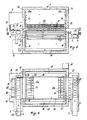
- Figure 3 is a schematic partial section through the freezer on the line III-III of Figure 1;
- Figure 4 is a schematic partial section through the freezer on the line IV-IV of Figure 3;
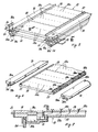
- Figure 5 is a perspective view of two plates forming part of the freezer and shown superposed and isolated from the remaining freezer structure;
- Figure 6 is a partial exploded view of one of the freezer plates;
- Figure 7 is a partial section through one of the plates on the line VII-VII of Figure 5; and
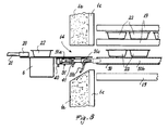
- Figure 8 is a schematic view to an enlarged scale of a portion of the freezer at its loading mouth, at which the device for feeding compressed air to the plate at rest at this mouth is provided.
- Figures 1 to 4 show an automatic freezer comprising an insulated housing 1, described hereinafter, containing a plurality of
refrigeration plates 19, also described hereinafter and shown in detail in Figures 5, 6 and 7 and devices for moving them and positioning them one at a time at the correct level in a loading station to be loaded with or unloaded of packages or containers enclosing the food products to be frozen, these devices not being described nor shown on the drawings as they comprise the normal frames, hydraulic cylinders and other parts used in this type of freezer and illustrated in the previous patents cited in the introduction to the present description. - The freezer also comprises a
loading device 2 for the packages orcontainers 22, which is also of well known type and commonly used in such freezers, for example of the types described in the patents US-A-3,557,975 and GB-B-1,259,073, with the difference that in the case of the present invention it is totally ducted and isolated from the outside environment. - A
conveyor belt 6 for the packages arriving at the housing 1 and aconveyor belt 7 for the packages leaving at the housing 1 are provided at the front and rear of the freezer respectively, those belts having that portion close to the the housing enclosed withinducts 3 and 4 which are connected together by achannel 5 to isolate the areas in which the packages are introduced into the housing 1 and discharged from it, so that the only apertures through which air can enter and leave are the apertures 3a and 4a, which have cross-sections just greater than that of thepackages 22, these apertures being provided with closure devices of known structure, which are normally closed and open only when the packages have to pass through them. In the embodiment shown on the drawings, a self-containedunit 8 is shown schematically for refrigerating and dehumidifying the air contained in the housing 1 and in theducts 3 and 4 connected to it, therefrigeration unit 8 being connected to the housing 1 by connectors and ducting 9 and 10 and being connected to theducts 3 and 4 by means of theconnection branch 11. - The purpose of the
unit 8 is to cool to a temperature similar to that of therefrigeration plates 19 and to continuously dehumidify both the air present within the freezer and the air which enters through theducts 3 and 4 together with the product to be frozen. or from other sources. - The refrigeration and
dehumidification unit 8 is put into operation before operating the freezer, ie before feeding the refrigerant fluid into the plates, in order to prevent frost forming or, them, the unit also circulating the cold dehumidified air within the freezer so that it aids heat transfer with the product to be frozen. - A
device 12 is provided to cool and dehumidify air withdrawn from the interior of the housing 1 (instead, but less advantageously, the air fed by thedevice 12 could be taken from the compressed air main of the factory in which the freezer operates), compress it, remove any traces of impurities and feed it to a device described hereinafter and shown in Figure 8, which then feeds it to theplate 19 which is at rest in the position for loading, and only to that plate. This air traverses channels provided in each plate but separate from those through which the refrigerant fluid circulates, to feed the holes provided in the upper surface of each plate, through which the air is expelled in the form of jets which create air cushions able to lift the packages of products to be frozen and allow them to be moved by theloading device 2 under zero or nearly zero friction conditions. - A fundamental characteristic of the described freezer is that it operates under zero humidity conditions within the housing 1, and thus with the plates cold but dry, without frost, and with heat transfer of mixed type, ie by direct contact between the packages and plates and by conduction to the cold air circulating within the housing 1.
- The freezer is suitable for freezing food products enclosed in parallelepiped packages (freezing improved by the absence of frost on the plates, ie by improved contact between the plates and packages) and products enclosed in trays either of non-parallelepiped shape or of low mechanical strength (it allowing these latter to be loaded, as loading is facilitated by the absence of friction and of adhesion with the plate, which if present result in forces which usually cause deformation of the packages when they are pushed in order to move along the plates).
- The housing 1 of the freezer according to the present invention is shown in vertical section in Figure 3 and in horizontal section in Figure 4.
- The front end wall 1a and the
rear end wall 1b, the term "front" meaning the end in which the product enters and the term "rear" meaning the end from which the product leaves, are both provided withinner backing walls front interspace 1c and arear interspace 1d. The two interspaces are divided into two parts by theproduct entry mouth 14 andproduct exit mouth 15, namely an upper part and a lower part, which are connected together bylateral ducts - On that face facing the interior of the housing 1, the
backing Walls interspace 1c is connected to the air refrigeration anddehumidification unit 8 by the ducts 9, theinterspace 1d being connected to the same unit by theducts - In the normal manner for this type of known freezer, the housing 1 houses a certain number of
plates 19 in a superposed arrangement spaced apart by spacers of adequate height for the product to be frozen, with refrigerant fluid circulating through each plate, and means for raising the plates, lowering them, moving them to the level of themouths - The loading device 2 (which as stated is totally housed and isolated from the outside) is located outside the housing 1, and is of the type usually used in such freezers (see for example the patents USA-A-3,557,975, USA-A-4,432,214, GB-B-1,259,073 etc.) but of which the drawings show only the
loading bar 20 and a small portion of thechains 21 which move thebar 20 forwards and backwards. - The purpose of the loading device is to transfer a row of
packages 22, carried by thebelt 6 and abutting against the stop element 23 (Figure 4) onto theplate 19 at rest in front of theloading mouth 14. - The
unit 8 is able to circulate the air which it has previously dehumidified and cooled to a temperature similar to that of theplates 19, by feeding it through the channels 9 into the lower part of theinterspace 1c and from here into the upper part of theinterspace 1c via thelateral channels 16, and to draw said air from the lower and upper parts of theinterspace 14, connected together by thelateral channels 17, viareturn channels unit 8. - The air is obliged to pass through the housing 1 and, in the region in which the
plates 19 are located, to infiltrate between them and into the spaces left free by thepackages 22, which air being at a temperature similar to the plates participates in the cooling of the product, to provide the same effect as that due to direct contact between the packages and the plates. It can be noted that this refrigerant effect due to the air is particularly important when the products have only one flat surface, such as when they are enclosed in plastic bags, because in this case the contact area between the packages and the plate above that onto which they are loaded is generally small, whereas the heat transfer due to the air is generally increased because the product is exposed to the air not only perimetrally but also on its top. - The dehumidified air circulation is metered by the
unit 8, and is controlled so as to occur essentially between thoseplates 19 not in front of themouths wall 13b, which is extremely close to the rear edge of theplates 19 so as not to allow the packages to fall from the plates. - The
plates 19 of the freezer according to the present invention are shown in Figures 5, 6 and 7. - Figure 5 shows two spacers one above the other and separated by
spacers 24 of height which matches the height of the product to be frozen. Said spacers can provide different distances between the plates if constructed in accordance with the patent US-A-4,841,881.Hoses plate 19 to manifolds (not shown on the drawings) for the circulation of the refrigerant fluid through the plates. -
Guides 27 are fixed on the upper surface of each plate to prevent thepackages 22 of product to be frozen from falling off the plate positioned at themouths - Figure 6 is an exploded view of one of the
plates 19. The central region of the plate consists of a series ofcentral elements 28 joined together usually by welding, to form a continuous plate traversed bychannels channels 28a being used to circulate the refrigerant fluid and thechannels 28b being used to feed air tosmall holes 28c provided along thechannels 28b through the upper surface of theelements 28. - On the lateral ends of the
elements 28 there are providedheaders 30 which are fixed to thecentral elements 28 by welding and are each traversed by twolongitudinal channels headers 30 positioned to the left in Figures 5 and 6 feed compressed air (via thechannels 30b) to thechannels 28b and from these to theholes 28c, and collect the refrigerant fluid leaving thechannels 28a of thecentral plate elements 28, this fluid leaving through thehoses 26 to be conveyed to a discharge manifold (not shown). - The
headers 30 positioned to the right in Figures 5 and 6 have theirchannel 30a connected via ahose 25 to a manifold (not shown) for feeding refrigerant fluid to thechannels 28a of eachplate element 28, theirchannel 30b feeding refrigerated and dehumidified compressed air to thechannels 28b of saidelements 28. - As the
channels 28b are closed at their ends and are connected to thechannels 30b of the twolateral manifolds 30 only via external tubes 31 (Figure 7), the refrigerant fluid circuit and the compressed air circuit can operate independently. - Figure 7 represents an enlarged part section through a
plate portion 19, this section being taken at achannel 28b to show the air path from thechannel 30b, through theexternal tubes 31 and into thechannel 28b, to then emerge from theholes 28c. - The ends of the
headers 30 are closed at thechannels 30a so that the refrigerant fluid flows through theelements 28 of each plate but is connected to them only via thehoses - The
air channels 30b are open at both ends to receive compressed air when the plate to which they are connected is at the discharge level in front of themouth 14, as shown in Figure 8. - The
unit 12 for drying, filtering and possibly removing oil from the compressed air is of known type and provides an adequate quantity of air which after cooling in theunit 8, in which the air passes through a separate circuit, is fed to four devices 31 (Figure 8) provided one at each open end of thechannels 30b of the twoheaders 30 of the plate at rest in the loading station. - The
devices 31 are therefore located at themouths plate 19 to be loaded with or unloaded ofpackages 22 stops. For simplicity, thedevice 31 is not shown in Figures 3 and 4, and it should be noted that in Figure 8 theplate 19 at rest in front of thedevice 31 is represented in simplified section, ie showing only that part relative to thechannel 30b of one of theheaders 30. - Figure 8 is therefore a schematic representation for showing the
inlet mouth 14 for theproduct 22 to be frozen and the location of thedevice 31. - Each of the four
devices 31 consists of a normal cylinder containing a piston driven by compressed air fed through theconnector piston rod 31a having its free end facing therelative header 30 and carrying ahollow connector 31c, the hollow portion being fed via a hose 31b with the air delivered by theunit 12. - The
connector 31c is shaped to mate with the front and rear apertures of thechannels 30b of eachheader 30 forming part of theplate 19 at rest in front of themouth 14. - Consequently, only the
plate 19 to be loaded is connected, when correctly positioned, by operating theair cylinder 31 which moves therod 31a to cause it to emerge (towards the right in Figure 8) and engage theconnector 31c, usually of rubber material to facilitate sealing, against the adjacent open end of thechannel 30b of theheader 30. - When engagement has taken place, valves (not shown for simplicity) provided in the circuit containing the air fed by the
unit 12 to the hose 31b, allow the compressed air to pass so that it enters thechannels 30b of theheaders 30, to then pass into theplate channels 28b and emerge from theholes 28c to lift thefood product packages 22, which thus become suspended on a cushion of air formed between the base of the packages and the upper surface of the plates, so that thepusher 20 can push the row of packages adjacent to it into the freezer, these packages themselves easily pushing the previous row of packages forwards as there is practically no resistance to movement, with the result that even extremely light and thus deformable packages can be used without such packages suffering any damage. - The independent unit for cooling and dehumidifying the air circulating within the housing 1 and directly associated with this latter need not be provided if the required air can be cooled by the general refrigeration plant of the factory in which the freezer is installed and operating.
Claims (4)
- A method for freezing food products in containers, characterised in that said containers are loaded into and frozen in a plate freezer within which a substantially moisture-free atmosphere is maintained together with dehumidified cold air circulation.
- A method as claimed in claim 1, characterised in that jets of dehumidified cold air are fed under the base of the containers resting on the plate positioned at the loading station to lift the containers from the plate surface.
- An automatic plate freezer for implementing the method claimed in claims 1 and 2, characterised by comprising means for cooling and dehumidifying the air present within the freezer and for maintaining it at low temperature and dehumidified, and means for generating and maintaining a cold dehumidified air stream between the plates within the freezer.
- A freezer as claimed in claim 3, characterised in that the automatic freezer plates comprise a plurality of channels in which holes are provided opening into the upper surface of each plate, means being provided for feeding cold dehumidified compressed air into said channels of that plate which is positioned at the station for loading the products to be frozen into the freezer.
Applications Claiming Priority (2)
| Application Number | Priority Date | Filing Date | Title |
|---|---|---|---|
| IT20075A IT1242050B (en) | 1990-04-19 | 1990-04-19 | METHOD FOR FREEZING FOOD PRODUCTS IN CONTAINERS AND AUTOMATIC PLATE FREEZER FOR IMPLEMENTATION OF THE METHOD |
| IT2007590 | 1990-04-19 |
Publications (2)
| Publication Number | Publication Date |
|---|---|
| EP0452844A1 true EP0452844A1 (en) | 1991-10-23 |
| EP0452844B1 EP0452844B1 (en) | 1993-07-21 |
Family
ID=11163603
Family Applications (1)
| Application Number | Title | Priority Date | Filing Date |
|---|---|---|---|
| EP91105961A Expired - Lifetime EP0452844B1 (en) | 1990-04-19 | 1991-04-15 | Method for freezing food products in containers, and an automatic plate freezer for implementing the method |
Country Status (4)
| Country | Link |
|---|---|
| US (1) | US5131241A (en) |
| EP (1) | EP0452844B1 (en) |
| DK (1) | DK0452844T3 (en) |
| IT (1) | IT1242050B (en) |
Cited By (5)
| Publication number | Priority date | Publication date | Assignee | Title |
|---|---|---|---|---|
| EP0602352A1 (en) * | 1992-12-16 | 1994-06-22 | Bäckerei Oswald Piller | Device for the freezing of food |
| WO1996031745A1 (en) * | 1995-04-05 | 1996-10-10 | Frigoscandia Equipment Ab | Method and device for air treatment |
| WO2007066132A1 (en) * | 2005-12-09 | 2007-06-14 | Oxford Biosensors Limited | Freeze drying of target substances |
| US9873547B2 (en) | 2013-03-15 | 2018-01-23 | Tippmann Companies Llc | Heat transfer system for warehoused goods |
| WO2021038603A1 (en) * | 2019-08-26 | 2021-03-04 | Skaginn Hf. | A method and device for homogeneous freezing |
Families Citing this family (5)
| Publication number | Priority date | Publication date | Assignee | Title |
|---|---|---|---|---|
| JPH11195803A (en) | 1998-01-06 | 1999-07-21 | Canon Inc | Solar battery module array |
| US20070212465A1 (en) * | 2006-03-13 | 2007-09-13 | Visram Shahzar A | Methods and apparatus for processing food |
| AU2009284698B2 (en) * | 2008-08-22 | 2016-06-02 | Feltrim Pastoral Company Pty. Limited | Automated unloading bare block plate freezer system |
| AU2012336238A1 (en) | 2011-11-10 | 2014-05-29 | Darin L. Chancellor | Combined impingement/plate freezer |
| USD732789S1 (en) | 2014-01-29 | 2015-06-23 | Tippmann Companies Llc | Palletized product spacer |
Citations (4)
| Publication number | Priority date | Publication date | Assignee | Title |
|---|---|---|---|---|
| FR2262913A1 (en) * | 1974-03-04 | 1975-10-03 | Tripier Jean Claude | Controlled temp. proving cupboard for bakers dough - has adjustably spacable shelves with horizontal air passages |
| FR2359579A1 (en) * | 1976-07-29 | 1978-02-24 | Pavailler Jacques | Bakery proving cabinet for controlled fermentation - by adjusting temp. of shelves through which heat transfer fluid is pumped |
| GB2120776A (en) * | 1982-05-18 | 1983-12-07 | Riscanco A S | Air diffuser |
| US4841881A (en) * | 1986-09-12 | 1989-06-27 | Stal Samifi S.P.A. | "Device for spacing apart, at desired distances, the refrigerating plates, in horizontal plate freezers" |
Family Cites Families (12)
| Publication number | Priority date | Publication date | Assignee | Title |
|---|---|---|---|---|
| US2882697A (en) * | 1956-07-27 | 1959-04-21 | Amerio Refrigerating Equipment | Automatic plate freezer for continuous freezing of food products |
| US3052339A (en) * | 1960-02-18 | 1962-09-04 | Champion Papers Inc | Conveying apparatus |
| US3020731A (en) * | 1960-07-08 | 1962-02-13 | Frank W Knowles | Spacer for freezer plates |
| US3271973A (en) * | 1964-09-18 | 1966-09-13 | Amerio Refrigerating Equipment | Automatic contact plate freezers |
| US3557975A (en) * | 1969-03-13 | 1971-01-26 | St Regis Paper Co | Pusher assembly for freezers |
| US4202436A (en) * | 1979-02-05 | 1980-05-13 | Crepaco, Inc. | Apparatus for handling a plurality of articles |
| US4240270A (en) * | 1979-04-27 | 1980-12-23 | The Stouffer Corporation | Adjustable spacers for flat plate conveyors |
| FR2461905A1 (en) * | 1979-07-23 | 1981-02-06 | Samifi Babcock Samifi Internal | DEVICE FOR INTRODUCING AND ADVANCING PRODUCTS ON PLATES IN A FREEZER WITH HORIZONTAL PLATES |
| IT1152323B (en) * | 1982-08-04 | 1986-12-31 | Babcock Samifi Spa | DEVICE FOR THE STORAGE AND AUTOMATIC COLLECTION OF ELEMENTS KNOWN AS INTERMEDIATE, SUITABLE FOR LOADING, ADVANCING AND UNLOADING OF CERTAIN PRODUCTS, FROM A HORIZONTAL PLATE FREEZER |
| US4423604A (en) * | 1982-09-14 | 1984-01-03 | Banquet Foods Corporation | Adjustable spacer for contact plate freezer |
| IT1226765B (en) * | 1987-07-31 | 1991-02-06 | Samifi Stal Spa | AUTOMATIC FREEZER WITH HORIZONTAL REFRIGERANT PLATES HAVING THE ABILITY TO COMPRESS THE PRODUCT DURING FREEZING. |
| DK164755C (en) * | 1987-10-30 | 1992-12-28 | Gram Brdr As | freezer |
-
1990
- 1990-04-19 IT IT20075A patent/IT1242050B/en active IP Right Grant
-
1991
- 1991-04-08 US US07/681,760 patent/US5131241A/en not_active Expired - Fee Related
- 1991-04-15 DK DK91105961.6T patent/DK0452844T3/en active
- 1991-04-15 EP EP91105961A patent/EP0452844B1/en not_active Expired - Lifetime
Patent Citations (4)
| Publication number | Priority date | Publication date | Assignee | Title |
|---|---|---|---|---|
| FR2262913A1 (en) * | 1974-03-04 | 1975-10-03 | Tripier Jean Claude | Controlled temp. proving cupboard for bakers dough - has adjustably spacable shelves with horizontal air passages |
| FR2359579A1 (en) * | 1976-07-29 | 1978-02-24 | Pavailler Jacques | Bakery proving cabinet for controlled fermentation - by adjusting temp. of shelves through which heat transfer fluid is pumped |
| GB2120776A (en) * | 1982-05-18 | 1983-12-07 | Riscanco A S | Air diffuser |
| US4841881A (en) * | 1986-09-12 | 1989-06-27 | Stal Samifi S.P.A. | "Device for spacing apart, at desired distances, the refrigerating plates, in horizontal plate freezers" |
Cited By (8)
| Publication number | Priority date | Publication date | Assignee | Title |
|---|---|---|---|---|
| EP0602352A1 (en) * | 1992-12-16 | 1994-06-22 | Bäckerei Oswald Piller | Device for the freezing of food |
| WO1996031745A1 (en) * | 1995-04-05 | 1996-10-10 | Frigoscandia Equipment Ab | Method and device for air treatment |
| US5832734A (en) * | 1995-04-05 | 1998-11-10 | Frigoscandia Equipment Ab | Methods and device for air treatment |
| WO2007066132A1 (en) * | 2005-12-09 | 2007-06-14 | Oxford Biosensors Limited | Freeze drying of target substances |
| US9873547B2 (en) | 2013-03-15 | 2018-01-23 | Tippmann Companies Llc | Heat transfer system for warehoused goods |
| US10301067B2 (en) | 2013-03-15 | 2019-05-28 | Tippmann Companies Llc | Heat transfer system for warehoused goods |
| US10807764B2 (en) | 2013-03-15 | 2020-10-20 | Tippmann Engineering LLC | Heat transfer system for warehoused goods |
| WO2021038603A1 (en) * | 2019-08-26 | 2021-03-04 | Skaginn Hf. | A method and device for homogeneous freezing |
Also Published As
| Publication number | Publication date |
|---|---|
| IT1242050B (en) | 1994-02-02 |
| IT9020075A1 (en) | 1991-10-19 |
| IT9020075A0 (en) | 1990-04-19 |
| US5131241A (en) | 1992-07-21 |
| DK0452844T3 (en) | 1993-08-30 |
| EP0452844B1 (en) | 1993-07-21 |
Similar Documents
| Publication | Publication Date | Title |
|---|---|---|
| EP0452844B1 (en) | Method for freezing food products in containers, and an automatic plate freezer for implementing the method | |
| US4712964A (en) | Storage system for products using supporting units | |
| CA2110760C (en) | Apparatus and method of freezing food | |
| US4432214A (en) | Device for insertion and feed of products on the plates in a horizontal plate freezer | |
| CA2682399C (en) | Tray-based continuous throughput blast freezer | |
| US20070169630A1 (en) | Thermal processing chamber and conveyor belt for use therein and method of processing product | |
| US9290323B2 (en) | Recirculating continuous storage apparatus | |
| US4345443A (en) | Apparatus for lowering the temperature of articles | |
| US2679323A (en) | Loading and unloading mechanism for quick freeze apparatus | |
| US20030034356A1 (en) | Commissioning system with product storage compartments disposed in a shelf and with a positionable ejector unit | |
| EP1009962B1 (en) | Method and apparatus of increasing efficiency in the freezing of individual items of food in a freezing tunnel | |
| US2615309A (en) | Refrigerating apparatus for freezing food | |
| US6725674B1 (en) | Device and method for cryogenic freezing | |
| EP0481969B1 (en) | Shop rack | |
| US2993345A (en) | Freezer apparatus | |
| US4629057A (en) | Distributing device | |
| WO2005037689A1 (en) | Accumulating refrigeration apparatus | |
| JPH0134068Y2 (en) | ||
| SU1330427A1 (en) | Quick-freezing machine for packed food products on pallets | |
| Briley | Blast freezing | |
| US2618131A (en) | Quick freeze apparatus and package | |
| CA2533223C (en) | A thermal processing chamber and conveyor belt for use therein and method of processing product | |
| GB2207407A (en) | Device for assuring a continuous portioning process | |
| AU2004281852A1 (en) | Accumulating refrigeration apparatus | |
| JPH04138016U (en) | Guide structure in ice vertical conveyance equipment |
Legal Events
| Date | Code | Title | Description |
|---|---|---|---|
| PUAI | Public reference made under article 153(3) epc to a published international application that has entered the european phase |
Free format text: ORIGINAL CODE: 0009012 |
|
| AK | Designated contracting states |
Kind code of ref document: A1 Designated state(s): DK FR GB SE |
|
| 17P | Request for examination filed |
Effective date: 19910920 |
|
| 17Q | First examination report despatched |
Effective date: 19921211 |
|
| GRAA | (expected) grant |
Free format text: ORIGINAL CODE: 0009210 |
|
| AK | Designated contracting states |
Kind code of ref document: B1 Designated state(s): DK FR GB SE |
|
| ET | Fr: translation filed | ||
| REG | Reference to a national code |
Ref country code: DK Ref legal event code: T3 |
|
| PGFP | Annual fee paid to national office [announced via postgrant information from national office to epo] |
Ref country code: FR Payment date: 19940317 Year of fee payment: 4 |
|
| PGFP | Annual fee paid to national office [announced via postgrant information from national office to epo] |
Ref country code: DK Payment date: 19940331 Year of fee payment: 4 |
|
| PGFP | Annual fee paid to national office [announced via postgrant information from national office to epo] |
Ref country code: SE Payment date: 19940418 Year of fee payment: 4 |
|
| PLBE | No opposition filed within time limit |
Free format text: ORIGINAL CODE: 0009261 |
|
| STAA | Information on the status of an ep patent application or granted ep patent |
Free format text: STATUS: NO OPPOSITION FILED WITHIN TIME LIMIT |
|
| 26N | No opposition filed | ||
| EAL | Se: european patent in force in sweden |
Ref document number: 91105961.6 |
|
| PG25 | Lapsed in a contracting state [announced via postgrant information from national office to epo] |
Ref country code: GB Effective date: 19950415 Ref country code: DK Effective date: 19950415 |
|
| REG | Reference to a national code |
Ref country code: DK Ref legal event code: EBP |
|
| PG25 | Lapsed in a contracting state [announced via postgrant information from national office to epo] |
Ref country code: SE Effective date: 19950416 |
|
| GBPC | Gb: european patent ceased through non-payment of renewal fee |
Effective date: 19950415 |
|
| PG25 | Lapsed in a contracting state [announced via postgrant information from national office to epo] |
Ref country code: FR Effective date: 19951229 |
|
| EUG | Se: european patent has lapsed |
Ref document number: 91105961.6 |
|
| REG | Reference to a national code |
Ref country code: FR Ref legal event code: ST |