EP0452158B1 - Moteur à combustion interne du type à monoarbre à cames en tête - Google Patents
Moteur à combustion interne du type à monoarbre à cames en tête Download PDFInfo
- Publication number
- EP0452158B1 EP0452158B1 EP91303290A EP91303290A EP0452158B1 EP 0452158 B1 EP0452158 B1 EP 0452158B1 EP 91303290 A EP91303290 A EP 91303290A EP 91303290 A EP91303290 A EP 91303290A EP 0452158 B1 EP0452158 B1 EP 0452158B1
- Authority
- EP
- European Patent Office
- Prior art keywords
- camshaft
- rocker arms
- intake valve
- rocker arm
- pair
- Prior art date
- Legal status (The legal status is an assumption and is not a legal conclusion. Google has not performed a legal analysis and makes no representation as to the accuracy of the status listed.)
- Expired - Lifetime
Links
Images


Classifications
-
- F—MECHANICAL ENGINEERING; LIGHTING; HEATING; WEAPONS; BLASTING
- F02—COMBUSTION ENGINES; HOT-GAS OR COMBUSTION-PRODUCT ENGINE PLANTS
- F02F—CYLINDERS, PISTONS OR CASINGS, FOR COMBUSTION ENGINES; ARRANGEMENTS OF SEALINGS IN COMBUSTION ENGINES
- F02F1/00—Cylinders; Cylinder heads
- F02F1/24—Cylinder heads
- F02F1/42—Shape or arrangement of intake or exhaust channels in cylinder heads
- F02F1/4214—Shape or arrangement of intake or exhaust channels in cylinder heads specially adapted for four or more valves per cylinder
-
- F—MECHANICAL ENGINEERING; LIGHTING; HEATING; WEAPONS; BLASTING
- F01—MACHINES OR ENGINES IN GENERAL; ENGINE PLANTS IN GENERAL; STEAM ENGINES
- F01L—CYCLICALLY OPERATING VALVES FOR MACHINES OR ENGINES
- F01L1/00—Valve-gear or valve arrangements, e.g. lift-valve gear
- F01L1/26—Valve-gear or valve arrangements, e.g. lift-valve gear characterised by the provision of two or more valves operated simultaneously by same transmitting-gear; peculiar to machines or engines with more than two lift-valves per cylinder
- F01L1/267—Valve-gear or valve arrangements, e.g. lift-valve gear characterised by the provision of two or more valves operated simultaneously by same transmitting-gear; peculiar to machines or engines with more than two lift-valves per cylinder with means for varying the timing or the lift of the valves
-
- F—MECHANICAL ENGINEERING; LIGHTING; HEATING; WEAPONS; BLASTING
- F02—COMBUSTION ENGINES; HOT-GAS OR COMBUSTION-PRODUCT ENGINE PLANTS
- F02B—INTERNAL-COMBUSTION PISTON ENGINES; COMBUSTION ENGINES IN GENERAL
- F02B1/00—Engines characterised by fuel-air mixture compression
- F02B1/02—Engines characterised by fuel-air mixture compression with positive ignition
- F02B1/04—Engines characterised by fuel-air mixture compression with positive ignition with fuel-air mixture admission into cylinder
-
- F—MECHANICAL ENGINEERING; LIGHTING; HEATING; WEAPONS; BLASTING
- F02—COMBUSTION ENGINES; HOT-GAS OR COMBUSTION-PRODUCT ENGINE PLANTS
- F02B—INTERNAL-COMBUSTION PISTON ENGINES; COMBUSTION ENGINES IN GENERAL
- F02B2275/00—Other engines, components or details, not provided for in other groups of this subclass
- F02B2275/20—SOHC [Single overhead camshaft]
-
- F—MECHANICAL ENGINEERING; LIGHTING; HEATING; WEAPONS; BLASTING
- F02—COMBUSTION ENGINES; HOT-GAS OR COMBUSTION-PRODUCT ENGINE PLANTS
- F02F—CYLINDERS, PISTONS OR CASINGS, FOR COMBUSTION ENGINES; ARRANGEMENTS OF SEALINGS IN COMBUSTION ENGINES
- F02F1/00—Cylinders; Cylinder heads
- F02F1/24—Cylinder heads
- F02F2001/244—Arrangement of valve stems in cylinder heads
- F02F2001/245—Arrangement of valve stems in cylinder heads the valve stems being orientated at an angle with the cylinder axis
Definitions
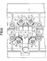
- the intake valve driving means 171 comprises a first driving rocker arm 241, operatively connected to the first intake valve V I1 , a second rocker arm 251 operatively connected to the second intake valve V I2 , and a free rocker arm 261, disposed between the driving rocker arms 241 and 251.
- the rocker arms 241, 251 and 261 are swingably carried by a rocker arm shaft 27 which is fixedly supported on the holder 20 and has an axis parallel to the camshaft 16 above the cam-shaft 16.
- the exhaust valve driving means 181 comprises a pair of exhaust valve-side rocker arms 291 and 301 swingably carried on a rocker arm shaft 28 which is fixedly supported on the holder 20 parallel to the rocker arm shaft 27 above the camshaft 16.
- the support plate 37 is provided with a bottomed cylindrical portion 37a opened downwardly in a location corresponding to the free rocker arm 261, and the guide member 39 is fitted into the bottomed cylindrical portion 37a with its opened end turned downwardly.
- a spring chamber 44 is defined between the piston 40 and the guide member 39.
- the first spring 42 has a relatively small spring constant and is provided in a compressed manner between a retainer 45 contained in the spring chamber 44 and the piston 40
- the second spring 43 has a relatively large spring constant and is provided in a compressed manner between the retainer 45 and a closed end of the guide member 39.
- an oil groove 47 is provided on the support plate 37 to extend in parallel to the cam shaft 16 adjacent a base end of the bottomed cylindrical portion 37a, and an oil passage 48 is provided in the base end of the bottomed cylindrical portion 37a and the guide member 39 for conducting oil flowing through the oil groove 47 into the spring chamber 44.
- lubricating oil can be supplied between the piston 40 and the guide member 39 by flowing of the lubricating oil through the oil groove 47.
- a retaining ring 62 is fitted on an inner surface of the second guide hole 60 and is capable of engaging the collar 53a of the restricting member 53, so that the restricting member 53 is inhibited from slipping out of the second guide hole 60 by the retaining ring 62. Moreover, the fitted position of the retaining ring 62 is determined to inhibit the further movement of the restricting member 53 toward the free rocker arm 261 from a state in which it is in abutment against the free rocker arm 261 in a location corresponding to a plane between the free rocker arm 261 and the second driving rocker arm 251.
- a swing pin 63 is embedded in the side surface of each of the first and second driving rocker arms 241 and 251 which is facing the free rocker arm 261 to engage the free rocker arm 261 while permitting the relatively swinging movement of the driving rocker arms 241 and 251 with the free rocker arm 261.
- connection switchover mechanism 50 is also arranged in a compact manner. This enables not only an easy improvement in dimensional accuracy of the components of the connection switchover mechanism 50 in order to provide a smooth operation of the connection switchover mechanism 50, but also contributes to a reduction in the weight of the rocker arms 241, 251 and 261.
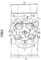
- a cam slipper 72 is provided at an intermediate and upper portion of the first driving rocker arm 242 to come into sliding contact with the lower speed cam 22 (see Fig. 3); a cam slipper 73 is provided at an intermediate and upper portion of the second driving rocker arm 252 to come into sliding contact with the lower speed cam 22 (see Fig. 3), and a cam slipper 74 is provided on the free rocker arm 262 to come into sliding contact with the higher speed cam 21 (see Fig. 3).
- cam slippers 75 and 76 are provided on intermediate and upper portions of the exhaust valve-side rocker arms 292 and 302 to come into sliding contact with the exhaust valve cams 23, 23 (see Fig. 3).
- a connection switchover mechanism 50′ is provided in the intake valve driving means 173 for switching-over the connection and disconnection of the rocker arms 243 and 253 and comprises a connection piston 83 movable in response to a hydraulic pressure from the hydraulic pressure supply passage 58 provided in the rocker arm shaft 27 between a position in which the first and second driving rocker arms 243 and 253 are connected and a position in which such connection is released, a restricting member 84 slidably received in the second driving rocker arm 253 and abutting against the connecting piston 83, and a return spring 85 interposed between the restricting member 84 and the second driving rocker arm 253 to bias the connecting piston 83 and the restricting member 84 toward a disconnecting side.
Claims (8)
- Moteur à combustion interne du type à monoarbre à cames en tête comprenant :
un arbre à cames unique (16) monté en rotation dans une culasse (2) au-dessus d'une chambre de combustion (5) ;
une paire de soupapes d'admission (VI1, VI2) montée dans ladite culasse (2) sur un côté dudit arbre à cames (16) ;
une pluralité de culbuteurs latéraux (24₃, 25₃ ; 24₄, 25₄, 26₄) de soupapes d'admission pour relier de façon opérante ledit arbre à cames (16) à ladite paire de soupapes d'admission (VI1, VI2) ;
une paire de soupapes d'échappement (VE1, VE2) montées sur la culasse (2) sur l'autre côté de l'arbre à cames (16) ;
une paire de culbuteurs latéraux (29₃, 30₃ ; 29₄, 30₄) de soupapes d'échappement pour pour relier de façon opérante ledit arbre à cames (16) séparément à chacune desdites paires de soupapes d'échappement (VE1, VE2) ; et
un trou de montage de bougie d'allumage dans une partie centrale d'un plafond de la chambre de combustion (5) ;
dans lequel ladite pluralité de culbuteurs latéraux (24₃, 25₃ ; 24₄, 25₄, 26₄) de soupapes d'admission est placée entre la paire de culbuteurs latéraux (29₃, 30₃ ; 29₄, 30₄) de soupapes d'échappement ;
caractérisé en ce qu'il est prévu un moyen (50′ ; 50) pour coupler et découpler sélectivement lesdits culbuteurs latéraux (24₃, 25₃ ; 24₄, 25₄, 26₄) de soupapes d'admission ; et en ce que
les culbuteurs latéraux de soupapes d'admission comprennent une paire de culbuteurs (24₃, 25₃ ; 24₄, 25₄) dont l'un (24₃, 24₄) comprend un galet (81 ; 89) qui est goupillé dessus pour un contact de roulement avec une came (79 ; 22) disposée sur l'arbre à cames (16) et l'autre (25₃ ; 25₄) comprend un patin (82 ; 91) qui y est disposé pour un contact de glissement avec une partie relevée (80) prévue sur l'arbre à cames (16), ladite partie relevée (80) étant formée de façon à ce qu'elle fasse en sorte que la soupape d'admission (VI1) associée audit culbuteur (25₃ ; 25₄) muni dudit patin (82 ; 91) s'ouvre d'une petite quantité seulement, afin de rendre la soupape d'admission (VI1) globalement inopérante quand le couplage entre lesdits un et autre culbuteurs (24₃, 25₃ ; 24₄, 25₄) est relâché. - Moteur à combustion interne du type à monoarbre à cames en tête selon la revendication 1, caractérisé en ce que ladite paire de culbuteurs (24₃, 25₃) sont disposés adjacents l'un par rapport à l'autre.
- Moteur à combustion interne du type à monoarbre à cames en tête selon la revendication 1, caractérisé en ce que ladite pluralité de culbuteurs latéraux (24₄, 25₄, 26₄) de soupapes d'admission comporte un culbuteur libre (26₄).
- Moteur à combustion interne du type à monoarbre à cames en tête selon la revendication 3, caractérisé en ce que ledit culbuteur libre (26₄) est interposé entre ladite paire de culbuteurs (24₄, 25₄).
- Moteur à combustion interne du type à monoarbre à cames en tête selon la revendication 4, caractérisé en ce que ledit moyen (50′), sélectivement, couple ledit culbuteur libre (26₄) à ladite paire de culbuteurs (24₄, 25₄) et l'en découple aussi.
- Moteur à combustion interne du type à monoarbre à cames en tête selon l'une quelconque des revendications précédentes, caractérisé en ce que ladite partie relevée (80) a une faible épaisseur suivant la direction axiale de l'arbre à came (16).
- Moteur à combustion interne du type à monoarbre à cames en tête selon l'une quelconque des revendications précédentes, caractérisé en ce qu'un tube d'introduction (65) de la bougie d'allumage est prévu entre lesdits culbuteurs latéraux (29₃, 30₃ ; 29₄, 30₄) de soupapes d'échappement et s'étend vers le trou de montage de la bougie d'allumage.
- Moteur à combustion interne du type à monoarbre à cames en tête selon la revendication 7, caractérisé en ce que ledit tube d'introduction (65) de la bougie d'allumage est incliné suivant un angle par rapport à l'axe d'un cylindre (3) de façon qu'une partie supérieure du tube (65) soit espacée de l'arbre à cames (16) entre les axes des soupapes d'échappement (VE1, VE2).
Priority Applications (1)
| Application Number | Priority Date | Filing Date | Title |
|---|---|---|---|
| EP94101321A EP0605390B1 (fr) | 1990-04-13 | 1991-04-15 | Moteur à combustion interne du type à mono-arbre à cames en tête |
Applications Claiming Priority (2)
| Application Number | Priority Date | Filing Date | Title |
|---|---|---|---|
| JP2097878A JPH0811930B2 (ja) | 1990-04-13 | 1990-04-13 | Sohc型多気筒内燃機関 |
| JP97878/90 | 1990-04-13 |
Related Child Applications (1)
| Application Number | Title | Priority Date | Filing Date |
|---|---|---|---|
| EP94101321.1 Division-Into | 1994-01-29 |
Publications (2)
| Publication Number | Publication Date |
|---|---|
| EP0452158A1 EP0452158A1 (fr) | 1991-10-16 |
| EP0452158B1 true EP0452158B1 (fr) | 1994-08-10 |
Family
ID=14204008
Family Applications (2)
| Application Number | Title | Priority Date | Filing Date |
|---|---|---|---|
| EP94101321A Expired - Lifetime EP0605390B1 (fr) | 1990-04-13 | 1991-04-15 | Moteur à combustion interne du type à mono-arbre à cames en tête |
| EP91303290A Expired - Lifetime EP0452158B1 (fr) | 1990-04-13 | 1991-04-15 | Moteur à combustion interne du type à monoarbre à cames en tête |
Family Applications Before (1)
| Application Number | Title | Priority Date | Filing Date |
|---|---|---|---|
| EP94101321A Expired - Lifetime EP0605390B1 (fr) | 1990-04-13 | 1991-04-15 | Moteur à combustion interne du type à mono-arbre à cames en tête |
Country Status (5)
| Country | Link |
|---|---|
| US (1) | US5095859A (fr) |
| EP (2) | EP0605390B1 (fr) |
| JP (1) | JPH0811930B2 (fr) |
| CA (1) | CA2040294C (fr) |
| DE (2) | DE69124708T2 (fr) |
Families Citing this family (29)
| Publication number | Priority date | Publication date | Assignee | Title |
|---|---|---|---|---|
| JP2517078Y2 (ja) * | 1990-04-13 | 1996-11-13 | 本田技研工業株式会社 | 内燃機関の動弁装置 |
| US5209201A (en) * | 1990-08-10 | 1993-05-11 | Honda Giken Kogyo Kabushiki Kaisha | Internal combustion engine |
| JP2588803B2 (ja) * | 1991-08-29 | 1997-03-12 | 本田技研工業株式会社 | 内燃機関 |
| JP2612788B2 (ja) * | 1991-09-04 | 1997-05-21 | 本田技研工業株式会社 | 内燃機関の動弁装置 |
| US5398649A (en) * | 1991-11-08 | 1995-03-21 | Yamaha Hatsudoki Kabushiki Kaisha | S.O.H.C. five valve engine |
| AU657040B2 (en) * | 1992-02-28 | 1995-02-23 | Mitsubishi Jidosha Kogyo Kabushiki Kaisha | Valve-moving apparatus for internal combustion engine |
| JP2792314B2 (ja) * | 1992-03-05 | 1998-09-03 | 三菱自動車工業株式会社 | 内燃機関の動弁装置 |
| US5241928A (en) * | 1992-03-13 | 1993-09-07 | Suzuki Motor Corp. | Movable valve device for engine |
| DE4227567C1 (de) * | 1992-08-20 | 1993-11-11 | Daimler Benz Ag | Ventilantriebssystem für eine mehrzylindrige Brennkraftmaschine |
| JP3319794B2 (ja) * | 1993-01-18 | 2002-09-03 | 本田技研工業株式会社 | 内燃機関のsohc型動弁装置 |
| DE4310735C1 (de) * | 1993-04-01 | 1994-05-26 | Audi Ag | Ventiltrieb für eine Brennkraftmaschine |
| GB2279405B (en) * | 1993-06-24 | 1996-02-21 | Audi Ag | Valve train for an internal combustion engine |
| JP2762213B2 (ja) * | 1993-08-18 | 1998-06-04 | 本田技研工業株式会社 | 内燃機関の動弁装置 |
| DE4404683C1 (de) * | 1994-02-15 | 1995-03-02 | Daimler Benz Ag | Verfahren zur Minimierung von Spiel in einem Ventiltrieb |
| JPH06299832A (ja) * | 1994-03-23 | 1994-10-25 | Mitsubishi Motors Corp | 可変バルブタイミング機構 |
| JP3388634B2 (ja) | 1994-06-15 | 2003-03-24 | 本田技研工業株式会社 | 内燃機関の動弁装置 |
| WO2001065075A1 (fr) | 2000-02-29 | 2001-09-07 | Bombardier-Rotax Gmbh | Dispositif de commande de tension pour moteur |
| JP4201617B2 (ja) * | 2003-02-24 | 2008-12-24 | 本田技研工業株式会社 | 内燃機関 |
| JP4357881B2 (ja) * | 2003-06-12 | 2009-11-04 | ヤマハ発動機株式会社 | 小型船舶 |
| JP2005264735A (ja) * | 2004-03-16 | 2005-09-29 | Yamaha Marine Co Ltd | 過給機付きエンジン |
| JP2006002633A (ja) * | 2004-06-16 | 2006-01-05 | Yamaha Marine Co Ltd | 水ジェット推進艇 |
| JP2006037730A (ja) | 2004-07-22 | 2006-02-09 | Yamaha Marine Co Ltd | 過給式エンジンの吸気装置 |
| JP2006083713A (ja) | 2004-09-14 | 2006-03-30 | Yamaha Marine Co Ltd | 過給装置の潤滑構造 |
| JP2007062432A (ja) | 2005-08-29 | 2007-03-15 | Yamaha Marine Co Ltd | 小型滑走艇 |
| JP4614853B2 (ja) * | 2005-09-26 | 2011-01-19 | ヤマハ発動機株式会社 | 過給機の取付構造 |
| EP2381074A1 (fr) * | 2010-04-20 | 2011-10-26 | Kwang Yang Motor Co., Ltd. | Mécanisme de levée de soupape variable et agencement pour soupape de contrôle d'huile |
| JP5738056B2 (ja) * | 2011-04-20 | 2015-06-17 | 本田技研工業株式会社 | 内燃機関の可変動弁機構 |
| JP5991938B2 (ja) * | 2013-03-07 | 2016-09-14 | 株式会社オティックス | 内燃機関の動弁機構 |
| JP6520909B2 (ja) * | 2016-12-26 | 2019-05-29 | トヨタ自動車株式会社 | エンジンの可変動弁機構 |
Citations (1)
| Publication number | Priority date | Publication date | Assignee | Title |
|---|---|---|---|---|
| EP0187287A2 (fr) * | 1984-12-10 | 1986-07-16 | Mazda Motor Corporation | Moteur à combustion interne |
Family Cites Families (16)
| Publication number | Priority date | Publication date | Assignee | Title |
|---|---|---|---|---|
| GB2148386B (en) * | 1983-10-22 | 1987-09-09 | Bl Tech Ltd | Cylinder head for spark ignition internal combustion engine |
| US4556025A (en) * | 1983-11-18 | 1985-12-03 | Mazda Motor Corporation | Engine valve mechanism having valve disabling device |
| JPS60175807U (ja) * | 1984-05-01 | 1985-11-21 | 本田技研工業株式会社 | 内燃機関におけるsohc型動弁機構の潤滑装置 |
| JPS6181507A (ja) * | 1984-09-04 | 1986-04-25 | Honda Motor Co Ltd | 内燃機関の動弁装置 |
| FR2578907B1 (fr) * | 1985-03-13 | 1989-06-16 | Peugeot | Dispositif d'actionnement de soupapes dans un moteur a combustion interne comportant quatre soupapes inclinees en v et une bougie centrale par cylindre |
| US4561391A (en) * | 1985-04-04 | 1985-12-31 | Ford Motor Company | Four valve for cylinder engine with single overhead camshaft |
| JPS61167107A (ja) * | 1985-09-20 | 1986-07-28 | Yamaha Motor Co Ltd | 小型車輛の頭上カム型エンジン |
| JPS6357806A (ja) * | 1986-08-27 | 1988-03-12 | Honda Motor Co Ltd | 内燃機関の動弁装置 |
| JPS63100210A (ja) * | 1986-10-16 | 1988-05-02 | Honda Motor Co Ltd | 内燃機関の動弁装置 |
| JPS63268908A (ja) * | 1987-04-27 | 1988-11-07 | Mazda Motor Corp | エンジンの動弁装置 |
| US4883027A (en) * | 1987-11-25 | 1989-11-28 | Honda Giken Kogyo Kabushiki Kaisha | Valve operating system for internal combustion engines |
| JPS63227911A (ja) * | 1988-03-11 | 1988-09-22 | Yamaha Motor Co Ltd | 1頭上カム軸式エンジン |
| JPS63235645A (ja) * | 1988-03-11 | 1988-09-30 | Yamaha Motor Co Ltd | 1頭上カム軸式エンジン |
| JP2694899B2 (ja) * | 1988-05-30 | 1997-12-24 | ヤマハ発動機株式会社 | 4サイクルエンジンの動弁装置 |
| JPS6477738A (en) * | 1988-08-20 | 1989-03-23 | Yamaha Motor Co Ltd | Engine having one overhead camshaft |
| JP2741691B2 (ja) * | 1989-04-28 | 1998-04-22 | スズキ株式会社 | 内燃機関の動弁機構 |
-
1990
- 1990-04-13 JP JP2097878A patent/JPH0811930B2/ja not_active Expired - Lifetime
-
1991
- 1991-04-11 CA CA002040294A patent/CA2040294C/fr not_active Expired - Lifetime
- 1991-04-12 US US07/684,657 patent/US5095859A/en not_active Expired - Lifetime
- 1991-04-15 EP EP94101321A patent/EP0605390B1/fr not_active Expired - Lifetime
- 1991-04-15 DE DE69124708T patent/DE69124708T2/de not_active Expired - Lifetime
- 1991-04-15 DE DE69103314T patent/DE69103314T2/de not_active Expired - Lifetime
- 1991-04-15 EP EP91303290A patent/EP0452158B1/fr not_active Expired - Lifetime
Patent Citations (1)
| Publication number | Priority date | Publication date | Assignee | Title |
|---|---|---|---|---|
| EP0187287A2 (fr) * | 1984-12-10 | 1986-07-16 | Mazda Motor Corporation | Moteur à combustion interne |
Also Published As
| Publication number | Publication date |
|---|---|
| EP0452158A1 (fr) | 1991-10-16 |
| US5095859A (en) | 1992-03-17 |
| CA2040294C (fr) | 1994-02-08 |
| DE69124708T2 (de) | 1997-05-28 |
| JPH0811930B2 (ja) | 1996-02-07 |
| JPH041405A (ja) | 1992-01-06 |
| EP0605390B1 (fr) | 1997-02-12 |
| EP0605390A1 (fr) | 1994-07-06 |
| DE69103314T2 (de) | 1994-12-01 |
| DE69124708D1 (de) | 1997-03-27 |
| CA2040294A1 (fr) | 1991-10-14 |
| DE69103314D1 (de) | 1994-09-15 |
Similar Documents
| Publication | Publication Date | Title |
|---|---|---|
| EP0452158B1 (fr) | Moteur à combustion interne du type à monoarbre à cames en tête | |
| US5592907A (en) | Valve operating system for multi-cylinder internal combustion engine | |
| EP0601250B1 (fr) | Dispositif de commande de soupapes pour moteur à combustion interne | |
| US4905639A (en) | Valve operating apparatus for an internal combustion engine | |
| JP2849939B2 (ja) | Sohc型内燃機関 | |
| US5537963A (en) | Valve operating system for multi-cylinder internal combustion engine | |
| EP0671550B1 (fr) | Dispositif de commande de soupape pour moteur à combustion interne | |
| EP0420139B1 (fr) | Moteur multisoupape | |
| US20030154942A1 (en) | Valve gear of internal combustion engine | |
| EP0524314B1 (fr) | Mecanisme de soupape dans un moteur a combustion interne | |
| EP0639693B1 (fr) | Dispositif de commande de soupape pour moteur à combustion interne | |
| US20020035989A1 (en) | Engine fuel pump mounting structure | |
| JP4201617B2 (ja) | 内燃機関 | |
| JPH0346642B2 (fr) | ||
| JP3358960B2 (ja) | Sohc型内燃機関 | |
| JP2668347B2 (ja) | Sohc型内燃機関 | |
| JPH08232623A (ja) | 内燃機関の動弁装置 | |
| JPH0364607A (ja) | 内燃機関の弁作動時期切換装置 | |
| JPS63106310A (ja) | 内燃機関の弁作動状態切換装置 | |
| JP2001349210A (ja) | 内燃機関の動弁装置 | |
| JPH01285612A (ja) | 内燃機関の弁作動状態切換装置 | |
| JP2002047908A (ja) | 内燃機関の動弁装置 | |
| JP2000154755A (ja) | 内燃機関の動弁装置 |
Legal Events
| Date | Code | Title | Description |
|---|---|---|---|
| PUAI | Public reference made under article 153(3) epc to a published international application that has entered the european phase |
Free format text: ORIGINAL CODE: 0009012 |
|
| AK | Designated contracting states |
Kind code of ref document: A1 Designated state(s): DE FR GB |
|
| 17P | Request for examination filed |
Effective date: 19910903 |
|
| 17Q | First examination report despatched |
Effective date: 19921005 |
|
| GRAA | (expected) grant |
Free format text: ORIGINAL CODE: 0009210 |
|
| AK | Designated contracting states |
Kind code of ref document: B1 Designated state(s): DE FR GB |
|
| XX | Miscellaneous (additional remarks) |
Free format text: TEILANMELDUNG 94101321.1 EINGEREICHT AM 15/04/91. |
|
| REF | Corresponds to: |
Ref document number: 69103314 Country of ref document: DE Date of ref document: 19940915 |
|
| ET | Fr: translation filed | ||
| PLBE | No opposition filed within time limit |
Free format text: ORIGINAL CODE: 0009261 |
|
| STAA | Information on the status of an ep patent application or granted ep patent |
Free format text: STATUS: NO OPPOSITION FILED WITHIN TIME LIMIT |
|
| 26N | No opposition filed | ||
| REG | Reference to a national code |
Ref country code: GB Ref legal event code: IF02 |
|
| PGFP | Annual fee paid to national office [announced via postgrant information from national office to epo] |
Ref country code: GB Payment date: 20050413 Year of fee payment: 15 |
|
| PG25 | Lapsed in a contracting state [announced via postgrant information from national office to epo] |
Ref country code: GB Free format text: LAPSE BECAUSE OF NON-PAYMENT OF DUE FEES Effective date: 20060415 |
|
| GBPC | Gb: european patent ceased through non-payment of renewal fee |
Effective date: 20060415 |
|
| PGFP | Annual fee paid to national office [announced via postgrant information from national office to epo] |
Ref country code: FR Payment date: 20100521 Year of fee payment: 20 |
|
| PGFP | Annual fee paid to national office [announced via postgrant information from national office to epo] |
Ref country code: DE Payment date: 20100430 Year of fee payment: 20 |
|
| REG | Reference to a national code |
Ref country code: DE Ref legal event code: R071 Ref document number: 69103314 Country of ref document: DE |
|
| PG25 | Lapsed in a contracting state [announced via postgrant information from national office to epo] |
Ref country code: DE Free format text: LAPSE BECAUSE OF EXPIRATION OF PROTECTION Effective date: 20110415 |