EP0452158B1 - SOHC type internal combustion engine - Google Patents
SOHC type internal combustion engine Download PDFInfo
- Publication number
- EP0452158B1 EP0452158B1 EP91303290A EP91303290A EP0452158B1 EP 0452158 B1 EP0452158 B1 EP 0452158B1 EP 91303290 A EP91303290 A EP 91303290A EP 91303290 A EP91303290 A EP 91303290A EP 0452158 B1 EP0452158 B1 EP 0452158B1
- Authority
- EP
- European Patent Office
- Prior art keywords
- camshaft
- rocker arms
- intake valve
- rocker arm
- pair
- Prior art date
- Legal status (The legal status is an assumption and is not a legal conclusion. Google has not performed a legal analysis and makes no representation as to the accuracy of the status listed.)
- Expired - Lifetime
Links
Images


Classifications
-
- F—MECHANICAL ENGINEERING; LIGHTING; HEATING; WEAPONS; BLASTING
- F02—COMBUSTION ENGINES; HOT-GAS OR COMBUSTION-PRODUCT ENGINE PLANTS
- F02F—CYLINDERS, PISTONS OR CASINGS, FOR COMBUSTION ENGINES; ARRANGEMENTS OF SEALINGS IN COMBUSTION ENGINES
- F02F1/00—Cylinders; Cylinder heads
- F02F1/24—Cylinder heads
- F02F1/42—Shape or arrangement of intake or exhaust channels in cylinder heads
- F02F1/4214—Shape or arrangement of intake or exhaust channels in cylinder heads specially adapted for four or more valves per cylinder
-
- F—MECHANICAL ENGINEERING; LIGHTING; HEATING; WEAPONS; BLASTING
- F01—MACHINES OR ENGINES IN GENERAL; ENGINE PLANTS IN GENERAL; STEAM ENGINES
- F01L—CYCLICALLY OPERATING VALVES FOR MACHINES OR ENGINES
- F01L1/00—Valve-gear or valve arrangements, e.g. lift-valve gear
- F01L1/26—Valve-gear or valve arrangements, e.g. lift-valve gear characterised by the provision of two or more valves operated simultaneously by same transmitting-gear; peculiar to machines or engines with more than two lift-valves per cylinder
- F01L1/267—Valve-gear or valve arrangements, e.g. lift-valve gear characterised by the provision of two or more valves operated simultaneously by same transmitting-gear; peculiar to machines or engines with more than two lift-valves per cylinder with means for varying the timing or the lift of the valves
-
- F—MECHANICAL ENGINEERING; LIGHTING; HEATING; WEAPONS; BLASTING
- F02—COMBUSTION ENGINES; HOT-GAS OR COMBUSTION-PRODUCT ENGINE PLANTS
- F02B—INTERNAL-COMBUSTION PISTON ENGINES; COMBUSTION ENGINES IN GENERAL
- F02B1/00—Engines characterised by fuel-air mixture compression
- F02B1/02—Engines characterised by fuel-air mixture compression with positive ignition
- F02B1/04—Engines characterised by fuel-air mixture compression with positive ignition with fuel-air mixture admission into cylinder
-
- F—MECHANICAL ENGINEERING; LIGHTING; HEATING; WEAPONS; BLASTING
- F02—COMBUSTION ENGINES; HOT-GAS OR COMBUSTION-PRODUCT ENGINE PLANTS
- F02B—INTERNAL-COMBUSTION PISTON ENGINES; COMBUSTION ENGINES IN GENERAL
- F02B2275/00—Other engines, components or details, not provided for in other groups of this subclass
- F02B2275/20—SOHC [Single overhead camshaft]
-
- F—MECHANICAL ENGINEERING; LIGHTING; HEATING; WEAPONS; BLASTING
- F02—COMBUSTION ENGINES; HOT-GAS OR COMBUSTION-PRODUCT ENGINE PLANTS
- F02F—CYLINDERS, PISTONS OR CASINGS, FOR COMBUSTION ENGINES; ARRANGEMENTS OF SEALINGS IN COMBUSTION ENGINES
- F02F1/00—Cylinders; Cylinder heads
- F02F1/24—Cylinder heads
- F02F2001/244—Arrangement of valve stems in cylinder heads
- F02F2001/245—Arrangement of valve stems in cylinder heads the valve stems being orientated at an angle with the cylinder axis
Definitions
- the intake valve driving means 171 comprises a first driving rocker arm 241, operatively connected to the first intake valve V I1 , a second rocker arm 251 operatively connected to the second intake valve V I2 , and a free rocker arm 261, disposed between the driving rocker arms 241 and 251.
- the rocker arms 241, 251 and 261 are swingably carried by a rocker arm shaft 27 which is fixedly supported on the holder 20 and has an axis parallel to the camshaft 16 above the cam-shaft 16.
- the exhaust valve driving means 181 comprises a pair of exhaust valve-side rocker arms 291 and 301 swingably carried on a rocker arm shaft 28 which is fixedly supported on the holder 20 parallel to the rocker arm shaft 27 above the camshaft 16.
- the support plate 37 is provided with a bottomed cylindrical portion 37a opened downwardly in a location corresponding to the free rocker arm 261, and the guide member 39 is fitted into the bottomed cylindrical portion 37a with its opened end turned downwardly.
- a spring chamber 44 is defined between the piston 40 and the guide member 39.
- the first spring 42 has a relatively small spring constant and is provided in a compressed manner between a retainer 45 contained in the spring chamber 44 and the piston 40
- the second spring 43 has a relatively large spring constant and is provided in a compressed manner between the retainer 45 and a closed end of the guide member 39.
- an oil groove 47 is provided on the support plate 37 to extend in parallel to the cam shaft 16 adjacent a base end of the bottomed cylindrical portion 37a, and an oil passage 48 is provided in the base end of the bottomed cylindrical portion 37a and the guide member 39 for conducting oil flowing through the oil groove 47 into the spring chamber 44.
- lubricating oil can be supplied between the piston 40 and the guide member 39 by flowing of the lubricating oil through the oil groove 47.
- a retaining ring 62 is fitted on an inner surface of the second guide hole 60 and is capable of engaging the collar 53a of the restricting member 53, so that the restricting member 53 is inhibited from slipping out of the second guide hole 60 by the retaining ring 62. Moreover, the fitted position of the retaining ring 62 is determined to inhibit the further movement of the restricting member 53 toward the free rocker arm 261 from a state in which it is in abutment against the free rocker arm 261 in a location corresponding to a plane between the free rocker arm 261 and the second driving rocker arm 251.
- a swing pin 63 is embedded in the side surface of each of the first and second driving rocker arms 241 and 251 which is facing the free rocker arm 261 to engage the free rocker arm 261 while permitting the relatively swinging movement of the driving rocker arms 241 and 251 with the free rocker arm 261.
- connection switchover mechanism 50 is also arranged in a compact manner. This enables not only an easy improvement in dimensional accuracy of the components of the connection switchover mechanism 50 in order to provide a smooth operation of the connection switchover mechanism 50, but also contributes to a reduction in the weight of the rocker arms 241, 251 and 261.
- a cam slipper 72 is provided at an intermediate and upper portion of the first driving rocker arm 242 to come into sliding contact with the lower speed cam 22 (see Fig. 3); a cam slipper 73 is provided at an intermediate and upper portion of the second driving rocker arm 252 to come into sliding contact with the lower speed cam 22 (see Fig. 3), and a cam slipper 74 is provided on the free rocker arm 262 to come into sliding contact with the higher speed cam 21 (see Fig. 3).
- cam slippers 75 and 76 are provided on intermediate and upper portions of the exhaust valve-side rocker arms 292 and 302 to come into sliding contact with the exhaust valve cams 23, 23 (see Fig. 3).
- a connection switchover mechanism 50′ is provided in the intake valve driving means 173 for switching-over the connection and disconnection of the rocker arms 243 and 253 and comprises a connection piston 83 movable in response to a hydraulic pressure from the hydraulic pressure supply passage 58 provided in the rocker arm shaft 27 between a position in which the first and second driving rocker arms 243 and 253 are connected and a position in which such connection is released, a restricting member 84 slidably received in the second driving rocker arm 253 and abutting against the connecting piston 83, and a return spring 85 interposed between the restricting member 84 and the second driving rocker arm 253 to bias the connecting piston 83 and the restricting member 84 toward a disconnecting side.
Description
- This invention relates to a single overhead camshaft (SOHC) type internal combustion engine comprising an intake valve driving means interposed between a single cam-shaft rotatably disposed above a combustion chamber and a pair of intake valves for converting the rotational motion of the camshaft into the opening and closing motions of the intake valves, an exhaust valve driving means interposed between the camshaft and a pair of exhaust valves for converting the rotational motion of the camshaft into the opening and closing motions of the exhaust valves, and a plug-insertion cylindrical portion disposed in a cylinder head for insertion of a spark plug which is to be disposed at a central portion of a ceiling surface of the combustion chamber.
- Such SOHC type internal combustion engine is conventionally known, for example, from Japanese Patent Application Laid-open No. 57806/88 and the like.
- In the above prior art, a plurality of intake valve-side rocker arms are interposed between a pair of intake valves and a camshaft and a pair of exhaust valve-side rocker arms are interposed between a pair of exhaust valves and the camshaft so that the pair of intake valves and the pair of exhaust valves are opened and closed by swingably driving the individual rocker arms by cams provided on the camshaft. In addition, a connection switchover mechanism is provided in the intake valve-side rocker arms and capable of switching-over the connection and disconnection of the rocker arms, in order to improve the output performance of the engine by varying the opening and closing mode of the intake valves in accordance with the operational condition of the engine.
- However, the intake valve-side rocker arms are adjacent one another in a location in which the connection switchover mechanism is provided, but the cams for the intake valve-side rocker arms and the cams for the exhaust valve-side rocker arms are provided alternately in an axial direction on the cam-shaft and hence, the intake valve-side rocker arms cannot be arranged in a compact manner. This provides an increase in size of the connection switchover mechanism, resulting in an increase in weight of the intake valve-side rocker arm, in a difficulty of improving the dimensional accuracy of the connection switchover mechanism, and in a difficulty of disposing the slide contact portion of the intake valve-side rocker arm with the cam and the operatively connected position of the intake valve-side rocker arm to the intake valve together in a plane perpendicular to the swinging axis of the intake valve-side rocker arm, thereby causing an uneven or eccentric load to act on the intake valve-side rocker arm.
- EP-A-0 258 061 shows another SOHC type internal combustion engine having a selective coupling between intake valve-side rocker arms.
- EP-A-0 187 287 and JP-A-1 301 909 both show SOHC type internal combustion engines wherein a plurality of intake valve-side rocker arms are positioned between a pair of exhaust valve-side rocker arms. However, there are difficulties with these arrangements in practice.
- Viewed from one aspect, the present invention provides a single overhead camshaft type internal combustion engine having:
a single camshaft rotatably mounted in a cylinder head above a combustion chamber;
a pair of intake valves mounted in said cylinder head on one side of said camshaft;
a plurality of intake valve-side driving rocker arms for operatively connecting said camshaft (16) to said pair of intake valves;
a pair of exhaust valves mounted on the cylinder head on the other side of the camshaft;
a pair of exhaust valve-side driving rocker arms for operatively connecting said camshaft separately to each of said pair of exhaust valves; and
a spark plug mounting hole in a central portion of a ceiling of the combustion chamber;
wherein said plurality of intake valve-side driving rocker arms are positioned between the pair of exhaust valve-side driving rocker arms;
characterised in that there is provided means for selectively connecting and disconnecting said intake valve-side driving rocker arms; and
the intake valve-side driving rocker arms include a pair of rocker arms of which one includes a roller pinned thereon for rolling contact with a cam provided on the camshaft and the other includes a slipper provided thereon for sliding contact with a raised portion provided on the camshaft, said raised portion being formed such that it causes the intake valve associated with said driving rocker arm provided with said slipper to open by a small amount only, such as to make that intake valve substantially inoperative when the connection between said one and other rocker arms is released. - Such arrangements have advantages, some of which will become apparent from the description of certain embodiments below.
- With such construction, in the intake valve driving means, the opening and closing mode of the intake valves can be changed in accordance with the operational condition of the engine by switching over the connection and disconnection of the plurality of rocker arms by operation of the connection switchover mechanism in accordance with the operational condition of the engine. This can contribute to an improvement in output from the engine. Moreover, the intake valve driving means can be constructed compactly by disposition of the plurality of rocker arms constituting the intake valve driving means adjacent one another in positions along and the camshaft. As a result, the connection switchover mechanism provided in the intake valve driving means can also be constructed compactly.
- Two embodiments will now be described, by way of example only, with reference to the accompanying drawings, wherein:
- Figs. 1 to 4 illustrate, by way of explanation, a first SOHC type internal combustion engine of the applicant, wherein
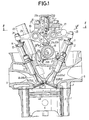
- Fig. 1 is a longitudinal sectional view of an engine body portion, taken along a line I-I in Fig. 2;
- Fig. 2 is a sectional view taken along a line II-II in Fig. 1;
- Fig. 3 is a sectional view taken along a line III-III in Fig. 1; and
- Fig. 4 is an enlarged sectional view taken along a line IV-IV in Fig. 1;
- Figs. 5 and 6 illustrate, also by way of explanation, a second SOHC type internal combustion engine of the applicant, wherein
- Fig. 5 is a longitudinal sectional view of an engine body portion, similar to Fig. 1; and
- Fig. 6 is a sectional view taken along a line VI-VI in Fig. 5;
- Figs. 7 to 9A illustrate a first embodiment of the present invention, wherein
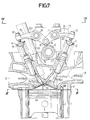
- Fig. 7 is a longitudinal sectional view of an engine body portion, similar to Fig. 1;
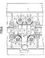
- Fig. 8 is a sectional view taken along a line VIII-VIII in Fig. 7;
- Fig. 8A is a view from above of a camshaft as shown dotted in Fig. 8;
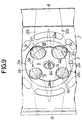
- Fig. 9 is a bottom view of a cylinder head, taken along a line IX-IX in Fig. 7; and
- Fig. 9A is a diagram illustrating the shape of a squish area;
- Fig. 10 is a bottom view of a cylinder head, similar to Fig. 9, but illustrating a modification of an intake passage;
- Figs. 11 to 12A illustrate a second embodiment of the present invention, wherein
- Fig. 11 is a longitudinal sectional view of an engine body portion, similar to Fig. 1;
- Fig. 12 is a sectional view taken along a line XII-XII in Fig. 10; and
- Fig. 12A is a view from above of a camshaft as shown dotted in Fig. 12.
- Referring first to Fig. 1 illustrating a first single overhead camshaft (SOHC) type internal combustion engine of the applicant, an essential portion of an engine body in an SOHC type multi-cylinder internal combustion engine is comprised of a
cylinder block 1 and acylinder head 2 coupled to an upper surface of thecylinder block 1. Apiston 4 having adepression 4a on an upper surface thereof is slidably received in acylinder 3 provided in thecylinder block 1, and acombustion chamber 5 is defined between the upper surface of thepiston 4 and thecylinder head 2. - Referring also to Fig. 2, first and second
intake valve openings exhaust valve openings cylinder head 2 and opened into a ceiling surface of thecombustion chamber 5. Theintake valve openings single intake port 8 opened in one side surface of thecylinder head 2, and theexhaust valve openings single exhaust port 9 opened in the other side surface of thecylinder head 2. A first intake valve VI1 and a second intake valve VI2 are slidably received in a pair ofcylindrical guides 10 disposed in thecylinder head 2, respectively, and adapted to open and close the first andsecond intake openings valve springs cylinder head 2 andretainers cylindrical guides 10, respectively, so that theintake valves valve springs exhaust valve openings cylindrical guides cylinder head 2. Coiledvalve spring cylinder head 2 andretainers cylindrical guides 13, respectively, so that the exhaust valves VE1 and VE2 are biased upwardly, i.e., in valve-closing direction by thevalve springs - An intake valve driving means 17₁, is interposed between the intake valves VI1 and VI2 and a
single camshaft 16 operatively connected to a crankshaft (not shown) at a reducing ratio of 1/2 for converting the rotational motion of thecamshaft 16 into the opening and closing motions of the intake valves VI1, and VI2, and an exhaust valve driving means 18₁ is interposed between the exhaust valves VE1 and VE2 and thecamshaft 16 for converting the rotational motion of thecamshaft 16 into the opening and closing motions of the exhaust valves VE1 and VE2. - Referring also to Fig. 2, the
camshaft 16 is rotatably carried by thecylinder head 2 and aholder 20 coupled to thecylinder head 2 and has a horizontal axis perpendicular to the axis of thecylinder 3. Thecamshaft 16 is integrally provided with ahigher speed cam 21 andlower speed cams higher speed cam 21 and further is integrally provided withexhaust valve cams lower speed cams higher speed cam 21 has a shape permitting the intake valves VI1 and VI2 to be opened and closed in a higher speed operational region of the engine and includes abase circle portion 21a and a raised portion 21b projecting radially outwardly from thebase circle portion 21a. Each of thelower speed cams 22 has a shape permitting the intake valves VI1 and VI2 to be opened and closed in a lower speed operational region of the engine and includes abase circle portion 22a and a raisedportion 22b projecting radially outwardly of thecamshaft 16 by a smaller amount than the raised portion 21b of thehigher speed cam 21 and over a region of a central angle smaller than that of the raised portion 21b. Further, theexhaust valve cam 23 has a shape permitting the exhaust valves VE1 and VE2 to be opened and closed in all the operational conditions of the engine. - The intake valve driving means 17₁ comprises a first
driving rocker arm 24₁, operatively connected to the first intake valve VI1, asecond rocker arm 25₁ operatively connected to the second intake valve VI2, and afree rocker arm 26₁, disposed between thedriving rocker arms rocker arms rocker arm shaft 27 which is fixedly supported on theholder 20 and has an axis parallel to thecamshaft 16 above the cam-shaft 16. The exhaust valve driving means 18₁ comprises a pair of exhaust valve-side rocker arms rocker arm shaft 28 which is fixedly supported on theholder 20 parallel to therocker arm shaft 27 above thecamshaft 16. - In the intake valve driving means 17₁, a cam slipper 31 is provided at one end of the first driving
rocker arm 24₁ and adapted to come into sliding contact with thelower speed cam 22 provided on thecamshaft 16, and a cam slipper (not shown) is provided at one end of the second drivingrocker arm 25₁ to come into sliding contact with thelower speed cam 22 provided on thecamshaft 16. A cam slipper (not shown) is provided on thefree rocker arm 26₁ to come into sliding contact with thehigher speed cam 21 provided on thecamshaft 16. In addition, acam slipper 34 is provided on one end of each of the exhaust valve-side rocker arms exhaust valve cams camshaft 16. - A
tappet screw 35 is threadedly engaged in the other end of each of the first and second drivingarms rocker arms tappet screw 36 is also threadedly engaged in the other end of each of therocker arms rocker arms - Referring again to Fig. 1, a
support plate 37 is fixedly mounted on theholder 20 above thecylinder head 2 in a position corresponding to a location betweenadjacent cylinders 3 to cover therocker arm shafts support plate 37 is provided with a lostmotion mechanism 38 for resiliently biasing thefree rocker arm 26₁ toward thehigher speed cam 21. - The lost
motion mechanism 38 comprises a bottomed cylindrical guide member 39 fitted in thesupport plate 37, a piston 40 slidably received in the guide member 39 and having an abutment portion shaped convergently at an end closer to thefree rocker arm 26₁ for abutment against thefree rocker arm 26₁, astopper 41 detachably secured to an inner surface of the guide member 39 closer to an opened end to engage the piston 40, and afirst spring 42 and a second spring 43 interposed between the piston 40 and the guide member 39 to resiliently bias the piston 40 in a direction to abut against thefree rocker arm 26₁. - The
support plate 37 is provided with a bottomedcylindrical portion 37a opened downwardly in a location corresponding to thefree rocker arm 26₁, and the guide member 39 is fitted into the bottomedcylindrical portion 37a with its opened end turned downwardly. A spring chamber 44 is defined between the piston 40 and the guide member 39. Thefirst spring 42 has a relatively small spring constant and is provided in a compressed manner between a retainer 45 contained in the spring chamber 44 and the piston 40, and the second spring 43 has a relatively large spring constant and is provided in a compressed manner between the retainer 45 and a closed end of the guide member 39. - A bottomed small hole 40b is made coaxially in an inner surface of a closed end of the piston 40, and the
first spring 42 having a relatively small spring constant is contained in the small hole 40b, whereby falling of the first spring is prevented. The abutment portion 40a of the piston 40 also has anair vent hole 46 made therein into a cross-shape opening in an outer surface of the abutment portion 40a and communicating with the outside of the spring chamber 44, in order to prevent the interior of the spring chamber 44 from being pressurized and depressurized during sliding movement of the piston 40. - Further, an oil groove 47 is provided on the
support plate 37 to extend in parallel to thecam shaft 16 adjacent a base end of the bottomedcylindrical portion 37a, and an oil passage 48 is provided in the base end of the bottomedcylindrical portion 37a and the guide member 39 for conducting oil flowing through the oil groove 47 into the spring chamber 44. Thus, lubricating oil can be supplied between the piston 40 and the guide member 39 by flowing of the lubricating oil through the oil groove 47. - Referring to Fig. 4, the intake valve driving means 17₁ is provided with a
connection switchover mechanism 50 capable of switching-over the connection and disconnection of therocker arms 24₁ to 26₁ in accordance with the operational condition of the engine. - The
connection switchover mechanism 50 comprises a first connectingpiston 51 capable of connecting the firstdriving rocker arm 24₁ and thefree rocker arm 26₁, a second connecting piston 52 capable of connecting thefree rocker arm 26₁ and the seconddriving rocker arm 25₁, a restrictingmember 53 for restricting the movement of the first and second connectingpistons 51 and 52, and a return spring 54 for biasing thepistons 51 and 52 and the restrictingmember 53 toward a disconnection position. - A first bottomed
guide hole 55 is provided in the firstdriving rocker arm 24₁ in parallel to therocker arm shaft 27 and opened toward thefree rocker arm 26₁. The first connectingpiston 51 is slidably received in thefirst guide hole 55, and ahydraulic pressure chamber 56 is defined between one end of the first connectingpiston 51 and a closed end of thefirst guide hole 55. A communication passage 57 is also provided in the firstdriving rocker arm 24₁ to communicate with thehydraulic pressure chamber 56, and a hydraulicpressure supply passage 58 is provided in therocker shaft 27 and leads to a hydraulic pressure supply source which is not shown. The hydraulicpressure supply passage 58 continually communicates with the communication passage 57 and thehydraulic pressure chamber 56 despite the swinging condition of the firstdriving rocker arm 24₁ by means of an internal groove (not numbered) in the firstdriving rocker arm 24₁. - A
guide hole 59 corresponding to thefirst guide hole 55 is provided in thefree rocker arm 26₁ to extend between opposite side surfaces thereof in parallel to therocker arm shaft 27, and the second connecting piston 52 abutting at one end thereof against the other end of the first connectingpiston 51 is slidably received in theguide hole 59. - A second bottomed
guide hole 60 corresponding to theguide hole 59 is provided in the seconddriving rocker arm 25₁ in parallel to therocker arm shaft 27 and is open toward thefree rocker arm 26₁. The bottomed cylindrical restrictingmember 53 abuts against the other end of the second connecting piston 52 and is slidably received in thesecond guide hole 60. The restrictingmember 53 is disposed with its open end turned to the closed end of thesecond guide hole 60, and acollar 53a projecting radially outwardly at the open end of themember 53 is in sliding contact with an inner surface of thesecond guide hole 60. The return spring 54 is mounted in a compressed manner between the closed end of thesecond guide hole 60 and a closed end of the restrictingmember 53, so that thepistons 51 and 52 and the restrictingmember 53 abut against one another and are biased toward thehydraulic pressure chamber 56 by the spring force of the return spring 54. Moreover, acommunication hole 61 for venting air and oil is provided at the closed end of thesecond guide hole 60. - A retaining
ring 62 is fitted on an inner surface of thesecond guide hole 60 and is capable of engaging thecollar 53a of the restrictingmember 53, so that the restrictingmember 53 is inhibited from slipping out of thesecond guide hole 60 by the retainingring 62. Moreover, the fitted position of the retainingring 62 is determined to inhibit the further movement of the restrictingmember 53 toward thefree rocker arm 26₁ from a state in which it is in abutment against thefree rocker arm 26₁ in a location corresponding to a plane between thefree rocker arm 26₁ and the seconddriving rocker arm 25₁. - In the
connection switchover mechanism 50, aswing pin 63 is embedded in the side surface of each of the first and seconddriving rocker arms free rocker arm 26₁ to engage thefree rocker arm 26₁ while permitting the relatively swinging movement of the drivingrocker arms free rocker arm 26₁. - Referring again to Figs. 1 and 2, a
spark plug 64 is disposed at a central portion of a ceiling surface of thecombustion chamber 5. Aplug pipe 65 is disposed in thecylinder head 2 and serves as a cylindrical plug-insertion portion for insertion of thespark plug 64. The pair of exhaust valve-side rocker arms exhaust valve cams camshaft 16 on opposite sides of theintake rocker arms valve rocker arms plug pipe 65 is positioned in thecylinder head 2 in such a manner that the axis thereof is disposed between the exhaust valves VE1 and VE2, i.e., located between the exhaust valves VE1 and VE2 as well as between the exhaust valve-side rocker arms plug pipe 65 is inclined so that the upper portion thereof is spaced from thecamshaft 16. Thespark plug 64 inserted into theplug pipe 65 is threadedly mounted in thecylinder head 2 at the central portion of the ceiling surface of thecombustion chamber 5. - The operation of the SOHC type internal combustion engine illustrated in Figs. 1 to 4 will be described. When the engine is in a lower speed operation, the hydraulic pressure in the
hydraulic pressure chamber 56 in theconnection switchover mechanism 50 is released, and thepistons 51 and 52 and the restrictingmember 53 are in their disconnected states in which they have been moved to the maximum extent toward thehydraulic pressure chamber 56 by the spring force of the return spring 54. In such condition, the abutment surfaces of the first and second connectingpistons 51 and 52 are in positions between the firstdriving rocker arm 24₁ and thefree rocker arm 26₁, while the abutment surfaces of the second connecting piston 52 and the restrictingmember 53 are in positions between thefree rocker arm 26₁ and the seconddriving rocker arm 25₁. Therefore, therocker arms - In such disconnected condition, the rotation of the cam-
shaft 16 causes the first and seconddriving rocker arms lower speed cams lower speed cams free rocker arm 26₁ is swung in response to the sliding contact with thehigher speed cam 21, but the swinging movement thereof exerts no influence on the first and seconddriving rocker arms exhaust valve cams - During a higher speed operation of the engine, a higher hydraulic pressure is supplied to the
hydraulic pressure chamber 56. This causes the first and second connectingpistons 51 and 52 as well as the restrictingmember 53 in theconnection switchover mechanism 50 of the intake valve driving means 17₁ to be moved toward the connecting positions against the spring force of the return spring 54, so that the first connectingpiston 51 is fitted into theguide hole 59, while at the same time, the second connecting piston 52 is fitted into thesecond guide hole 60, thereby connecting therocker arms free rocker arm 26₁ in sliding contact with thehigher speed cam 21 is largest and therefore, the first and seconddriving rocker arms free rocker arm 26₁, and the intake valves VI1 and VI2 are opened and closed at a timing and a lift amount corresponding to the shape of thehigher speed cam 21. - During this higher speed operation, the exhaust valve-
side rocker arms exhaust valve cams - It is possible to provide an improvement in output from the engine with a valve operating characteristic adapted for the operational condition of the engine by changing the opening and closing mode of the intake valves VI1 and VI2 between the higher and lower speed operations in this manner.
- In such an internal combustion engine, in the position corresponding to the
camshaft 16, therocker arms connection switchover mechanism 50 is also arranged in a compact manner. This enables not only an easy improvement in dimensional accuracy of the components of theconnection switchover mechanism 50 in order to provide a smooth operation of theconnection switchover mechanism 50, but also contributes to a reduction in the weight of therocker arms driving rocker arms lower speed cams rocker arm shaft 27, thereby avoiding the action of an uneven or eccentric load on the first andsecond rocker arms - The
plug pipe 65 is disposed in thecylinder head 2 with its axis located between the exhaust valves VE1 and VE2 thereby effectively utilizing the space produced by positioning the exhaust valve-side rocker arms - Figs. 5 and 6 illustrate a second SOHC type internal combustion engine of the applicant, wherein parts that are similar or identical to those in the previously described arrangement are identified by the same reference characters.
- A
camshaft 16 is rotatably carried by thecylinder head 2 and acam holder 71 coupled to thecylinder head 2. Integrally provided on thecamshaft 16 in an arrangement similar to that shown in Fig. 3 illustrating the first arrangement are ahigher speed cam 21,lower speed cams higher speed cam 21, and exhaust valve-side cams lower speed cams rocker arm shaft 70 parallel to the cam-shaft 16 is fixedly supported in thecylinder head 2 below thecamshaft 16. An intake valve driving means 17₂ is provided between the intake valves VI1 and VI2 and thecamshaft 16 for converting the rotational motion of thecamshaft 16 to the opening and closing motions of the intake valves VI1 and VI2, and an exhaust valve driving means 18₂ is provided between the exhaust valves VE1 and VE2 and thecamshaft 16 for converting the rotational motion of thecamshaft 16 to the opening and closing motions of the exhaust valves VE1 and VE2. - The intake valve driving means 17₂ comprises a first
driving rocker arm 24₂ operatively connected to the first intake valve VI1, a seconddriving rocker arm 25₂ operatively connected to the second intake valve VI2, and afree rocker arm 26₂ disposed between the drivingrocker arms rocker arms rocker arm shaft 70. The exhaust valve driving means 18₂ comprises exhaust valve-side rocker arms rocker arm shaft 70 and operatively connected separately to the exhaust valves VE1 and VE2. - In the intake valve driving means 17₂, a
cam slipper 72 is provided at an intermediate and upper portion of the firstdriving rocker arm 24₂ to come into sliding contact with the lower speed cam 22 (see Fig. 3); acam slipper 73 is provided at an intermediate and upper portion of the seconddriving rocker arm 25₂ to come into sliding contact with the lower speed cam 22 (see Fig. 3), and acam slipper 74 is provided on thefree rocker arm 26₂ to come into sliding contact with the higher speed cam 21 (see Fig. 3). In addition,cam slippers side rocker arms exhaust valve cams 23, 23 (see Fig. 3). - A lost
motion mechanism 38′ having the basically same construction as the lostmotion mechanism 38 in the first arrangement is provided in thecylinder head 2 to resiliently bias thefree rocker arm 26₂ in the intake valve driving means 17₂ toward thecamshaft 16. - Further, a connection switchover mechanism (not shown) having the basically same construction as the
connection switchover mechanism 50 in the first arrangement is provided in the intakevalve driving mechanism 17₂ to switchover the connection and disconnection of therocker arms - A lubricating
oil supply passage 77 is provided in therocker arm shaft 70 parallel to the hydraulicpressure supply passage 58, and injectingnozzles 78 are provided at base portions of therocker arms oil supply passage 77 in accordance with the swing positions of therocker arms oil supply passage 77 toward their sliding contact portions with thecamshaft 16. - It should be noted that the pair of
rocker arms camshaft 16. Therefore, it is possible to ensure a relatively wide space between the exhaust valve-side rocker arms plug pipe 65 may be disposed in thecylinder head 2 between the exhaust valves VE1 and VE2 as well as between the exhaust valve-side rocker arms - Thus, with such second arrangement, it is possible to ensure a space for the
plug pipe 65 with a compact entire arrangement, notwithstanding the provision of the connection switchover mechanism in the intake valve driving means 17₂. - Figs. 7 to 9A illustrate a first embodiment of the present invention, wherein parts similar or identical to those in the previous arrangements are identified by the same reference characters.
- Referring first to Figs. 7, 8 and 8A, a
camshaft 16 is rotatably carried by acylinder head 2 and aholder 20 coupled to thecylinder head 2. An intake valve driving means 17₃ is provided between thecamshaft 16 and the intake valves VI1 and VI2 for converting the rotational motion of thecamshaft 16 into the opening and closing motions of the intake valves VI1 and VI2, and an exhaust valve driving means 18₃ is provided between the exhaust valves VE1 and VE2 and thecamshaft 16 for converting the rotational motion of thecamshaft 16 into the opening and closing motions of the exhaust valves VE1 and VE2. - The intake valve driving means 17₃ comprises a first
driving rocker arm 24₃ operatively connected to the first intake valve VI1, and a seconddriving rocker arm 25₃ operatively connected to the second intake valve VI2 and disposed adjacent the firstdriving rocker arm 24₃. Therocker arms rocker shaft 27. The exhaust valve driving means 18₃ comprises exhaustvalve rocker arms rocker arm shaft 28. - A
connection switchover mechanism 50′ is provided in the intake valve driving means 17₃ for switching-over the connection and disconnection of therocker arms pressure supply passage 58 provided in therocker arm shaft 27 between a position in which the first and seconddriving rocker arms driving rocker arm 25₃ and abutting against the connecting piston 83, and areturn spring 85 interposed between the restricting member 84 and the seconddriving rocker arm 25₃ to bias the connecting piston 83 and the restricting member 84 toward a disconnecting side. - In the intake valve driving means 17₃, a
roller 81 is pinned at one end of the firstdriving rocker arm 24₃ to come into rolling contact with thecam 79 integrally provided on thecamshaft 16, and aslipper 82 is provided at one end of the seconddriving rocker arm 25₃ to come into sliding contact with a raisedportion 80 integrally provided on the cam-shaft 16 adjacent thecam 79. The raisedportion 80 is basically formed to have an outer surface that is circular about the axis of thecamshaft 16, but also to have a shape such that the second intake valve VI2 is slightly operated in an opening direction while being in a substantially closed state, when the first intake valve VI1 is opened by the firstdriving rocker arm 24₃ in a condition in which the seconddriving rocker arm 25₃ is not connected with the firstdriving rocker arm 24₃. Moreover, the width of the raisedportion 80 in a direction along the axis of thecamshaft 16 is relatively small, and the width of theslipper 82 provided on the seconddriving rocker arm 25₃ is also small in correspondence to the raisedportion 80 because very little force is transmitted therebetween. -
Rollers side rocker arms side cams shaft 16 on opposite sides of thecam 79 and the raisedportion 80 provided on thecamshaft 16 adjacent each other, respectively. - Thus, the pair of the exhaust valve-
side rocker arms camshaft 16, and therefore, it is possible to ensure a relatively wide space between the exhaustvalve rocker arms plug pipe 65 may be disposed in thecylinder head 2 between the exhaust valves VE1 and VE2 as well as between the exhaust valve-side rocker arms - Referring also to Fig. 9, an
intake passage 97₁ provided in thecylinder head 2 in communication with the firstintake valve opening 6₁ and anintake passage 97₂ provided in thecylinder head 2 in communication with the secondintake valve opening 6₂ are commonly connected to anintake port 8 provided in one side surface of thecylinder head 2 for eachcylinder 3. One of the intake passages, such aspassage 97₁, is formed in an inwardly expanded and curved fashion to extend along the inner surface of thecombustion chamber 5 just in front of the firstintake valve opening 6₁, in order to provide a swirl suction of the gas from the firstintake valve opening 6₁ into thecombustion chamber 5, when the second intake valve VI2 has become substantially inoperative. - A
recess 2a is provided on a lower surface of thecylinder head 2 to form a ceiling surface of thecombustion chamber 5, and asquish area 98 is provided between an opened edge of therecess 2a and a top surface of thepiston 4 at the top dead center point. The opened edge of therecess 2a is shaped such that the following edge portions are connected together: a first peripheral edge 2a₁ corresponding to an inner periphery of the cylinder extending from the firstintake valve opening 6₁ to the first exhaust valve opening 7₁ in adirection 99 of swirl suction from the firstintake valve opening 6₁ into thecombustion chamber 5; a second peripheral edge portion 2a₂ corresponding to a peripheral edge of thecircular depression 4a in thepiston 4 between the first and secondexhaust valve openings depression 4a between the secondexhaust valve opening 7₂ and the secondintake valve opening 6₂; and a fourth peripheral edge portion 2a₄ corresponding to the peripheral edge of thedepression 4a between the second and firstintake valve opening squish area 98 has a shape as shown by the cross-hatched region in Fig. 9A and is not formed in a section extending from the firstintake valve opening 6₁ to the first exhaust valve opening 7₁ in thedirection 99 of swirl suction. In those portions of thesquish area 98 which correspond to locations between theintake valve openings exhaust valve openings squish area 98 is opposed to the peripheral edge of thedepression 4a at the upper and central portion in thepiston 4. - With such first embodiment, in a higher speed operation condition of the engine, the first and second
driving rocker arms cam 79. On the other hand, in a lower speed operational condition of the engine, the connection of the first and seconddriving rocker arms cam 79 by the firstdriving rocker arm 24₃ in slide contact with thecam 79, while the seconddriving rocker arm 25₃ in slide contact with the raisedportion 80 can be brought into a substantially inoperative state to put the second intake valve VI2 substantially out of operation. However, the second intake valve VI2 is not completely inoperative and can be slightly operated in the opening direction when the first intake valve VI1 is opened. This makes it possible to prevent sticking of the second intake valve VI2 to the valve seat which may be otherwise produced when a completely closed state is maintained. - In the lower speed operational condition of the engine in which the second intake valve VI2 is substantially inoperative and only the first intake valve VI1 is opened and closed, a fuel-air mixture from the
intake port 8 is supplied via theintake passage 97₁ and the firstintake valve opening 6₁ into thecombustion chamber 5, so that a swirl is produced in thecombustion chamber 5. Moreover, theintake passage 97₁ is formed in a curved fashion to extend tangentially along the inner surface of thecombustion chamber 5 just in front of the firstintake valve opening 6₁, so that the fuel-air mixture is drawn into thecombustion chamber 5 while being whirled, enabling a swirl to be produced effectively. - The fuel-air mixture introduced into the
combustion chamber 5 through the firstintake valve opening 6₁ flows within thecombustion chamber 5 in the direction of swirl suction, but because thesquish area 98 is not formed in the section from the firstintake valve opening 6₁ to the first exhaust valve opening 7₁ in thedirection 99 of swirl suction, a squish flow is prevented from acting on the whirled flow just introduced into thecombustion chamber 5 through the firstintake valve opening 6₁ in a direction that otherwise would disturb the whirling of such flow, thereby effectively forming a swirl in thecombustion chamber 5. - Further, the inner periphery of the
squish area 98 is formed in opposition to the peripheral edge of thedepression 4a at the central portion of the upper surface of thepiston 4 between theintake valve openings exhaust valve openings combustion chamber 5, which makes it possible to form a more effective swirl withinthe.combustion chamber 5. - It is possible to provide an improvement in burning property by forming a powerful swirl within the
combustion chamber 5 in this manner. - It should be noted that the first
driving rocker arm 24₃ which is in operation in a lower speed region in which the component, in the valve operating system, of the friction loss in the entire engine constitutes a larger proportion is in rolling contact with thecam 79 through theroller 81, and this can contribute to a reduction in friction loss due to the valve operating system in the lower speed region and thus a reduction in friction loss in the entire engine. Moreover, because the exhaust valve-side rocker arms exhaust valve cams rollers - Further, the second
driving rocker arm 25₃ is in slide contact with the raisedportion 80 through theslipper 82 and this ensures that the width of theslipper 8 2 can be smaller than that of theroller 81. Moreover, because the intake valve driving means 17₃ is comprised of the pair of drivingrocker arms cam shaft 16, as compared with the intake valve driving means constructed of three rocker arms as in the previously described arrangements. - Moreover, as in the previous arrangements, the entire construction can be made compact, notwithstanding the provision of the
connection switchover mechanism 50′ in the intake valve driving means 17₃. - In the above first embodiment, the
intake passage 97₁ has been formed in the curved fashion just in front of the firstintake valve opening 6₁, but it will be understood that theintake passage 97₁ may be disposed with the position of theintake port 8 being displaced toward the secondintake valve opening 6₂, as compared with Fig. 9, so as to extend substantially along the inner surface of thecombustion chamber 5 over the entire length of thepassage 97₁ from the connection with theintake port 8 to the firstintake valve opening 6₁. This modified form is shown in Fig. 10. - Figs. 11, 12 and 12A illustrate a second embodiment of the present invention, wherein parts that are similar or identical to those in the previous arrangements are identified by the same reference characters.
- An intake valve driving means 17₄ is provided between the
camshaft 16 and the intake valves VI1 and VI2 for converting the rotational motion of thecamshaft 16 into the opening and closing motions of the intake valves VI1 and VI2, and an exhaust valve driving means 18₄ is provided between the exhaust valves VE1 and VE2 and thecamshaft 16 for converting the rotational motion of thecamshaft 16 into the opening and closing motions of the exhaust valves VE1 and VE2. - The intake valve driving means 17₄ comprises a first
driving rocker arm 24₄ operatively connected to the first intake valve VI1, a second driving rocker arm 25₄ operatively connected to the second intake valve VI2, and a free rocker arm 26₄ disposed between the drivingrocker arms 24₄ and 25₄ and capable of becoming free from the intake valves VI1 and VI2. Therocker arms 24₄, 25₄ and 26₄ are swingably carried at their intermediate portions by therocker arm shaft 27. The exhaust valve driving means 18₄ comprises exhaust valve-side rocker arms rocker arm shaft 28. - A
connection switchover mechanism 50 is provided in the intake valve driving means 17₄ and is capable of switching-over the connection and disconnection of therocker arms 24₄, 25₄ and 26₄. Integrally provided on thecamshaft 16 are ahigher speed cam 21 formed so that it is operative primarily during a higher speed operation of the engine, alower speed cam 22 as a second cam formed adjacent thehigher speed cam 21, so that it is operative primarily during a lower speed operation of the engine, and a raisedportion 80 adjacent thehigher speed cam 21 on the opposite side from thelower speed cam 22. Further, in the intake valve driving means 17₄, aroller 89 is pinned at one end of the firstdriving rocker arm 24₄ to come into rolling contact with thelower speed cam 22; aslipper 90 is provided at one end of the free rocker arm 26₄ to come into sliding contact with thehigher speed cam 21, and aslipper 91 is provided at one end of the second driving rocker arm 25₄ to come into sliding contact with the raisedportion 80. Moreover, the width of the raisedportion 80 in a direction along the axis of thecamshaft 16 is relatively small, and the width of theslipper 91 provided on the second rocker arm 25₄ is also small in correspondence to the raisedportion 80. -
Rollers side rocker arms exhaust valve cams camshaft 16 on opposite sides of thelower speed cam 22 and the raisedportion 80, respectively. - Thus, the pair of exhaust valve-
side rocker arms camshaft 16 and therefore, it is possible to insure a relatively wide space between the exhaustvalve rocker arms plug pipe 65 may be positioned in thecylinder head 2 between the exhaust valves VE1 and VE2 as well as between the exhaust valve-side rocker arms - With such second embodiment, in a higher speed operational condition of the engine, the first and second
driving rocker arms 24₄ and 25₄ and the free rocker arm 26₄ are interconnected, so that the intake valves VI1 and VI2 can be opened and closed at a timing and a lift amount corresponding to the shape of thehigher speed cam 21. In a lower speed operational condition of the engine, the connection of the firstdriving rocker arm 24₄ and the free rocker arm 26₄ as well as the connection of the free rocker arm 26₄ and the second driving rocker arm 25₄ can be released, so that the first intake valve VI1 can be opened and closed at a timing and a lift amount corresponding to the shape of thelower speed cam 22 by the firstdriving rocker arm 24₄ which is in rolling contact with thelower speed cam 22, while the second driving rocker arm 25₄ in sliding contact with the raisedportion 80 can be brought into a substantially inoperative state to put the second intake valve VI2 substantially out of operation. - The first
driving rocker arm 24₄ operative in a lower speed region is in rolling contact with thelower speed cam 22 through theroller 89, which can contribute to a reduction in friction loss in the valve-operating system in the lower speed region and thus a reduction in friction loss in the entire engine. In addition, because the exhaust valve-side rocker arms exhaust valve cams rollers - Further, the second driving rocker arm 25₄ is in sliding contact with the raised
portion 80 through theslipper 91 and therefore, the width of theslipper 91 can be smaller than that of theroller 89. This ensures that the intake valve driving means 17₄ can be constructed more compactly along the axis of thecamshaft 16, as compared with those in the arrangements described with reference to Figures 1 to 6. - Moreover, the entire arrangement can be made compact as in the previous arrangements notwithstanding the provision of the
connection switchover mechanism 50 in the intake valve driving means 17₄. - In the foregoing embodiments, the connection switchover mechanism has been described as being provided in the rocker arms constituting the intake valve driving means for switching-over the connection and disconnection of all the rocker arms, but it will be understood that the connection switchover mechanism may be constructed to switch-over the connection and disconnection of only a pair of adjacent rocker arms.
- Thus, in at least preferred embodiments there is provided an SOHC type internal combustion engine including a pair of intake valves and a pair of exhaust valves, wherein the intake valve driving means can be constructed compactly, whereby the opening and closing mode of the intake valves can be changed in accordance with the operational condition of the engine; and there is ensured a space for disposition of the plug insertion cylindrical portion, while providing a compact entire valve-operating system; and there is provided a reduction in friction loss in the lower speed region in which the component, in the valve-operating system, of the friction loss in the entire engine constitutes a larger proportion and thus a reduction in friction loss in the entire engine, and to provide a compact construction of the intake valve driving means.
Claims (8)
- A single overhead camshaft type internal combustion engine having:
a single camshaft (16) rotatably mounted in a cylinder head (2) above a combustion chamber (5);
a pair of intake valves (VI1,VI2) mounted in said cylinder head (2) on one side of said camshaft (16);
a plurality of intake valve-side driving rocker arms (24₃,25₃; 24₄,25₄,26₄) for operatively connecting said camshaft (16) to said pair of intake valves (VI1, VI2);
a pair of exhaust valves (VE1, VE2) mounted on the cylinder head (2) on the other side of the camshaft (16);
a pair of exhaust valve-side driving rocker arms (29₃,30₃; 29₄,30₄) for operatively connecting said camshaft (16) separately to each of said pair of exhaust valves (VE1,VE2); and
a spark plug mounting hole in a central portion of a ceiling of the combustion chamber (5);
wherein said plurality of intake valve-side driving rocker arms (24₃,25₃; 24₄,25₄,26₄) are positioned between the pair of exhaust valve-side driving rocker arms (29₃, 30₃; 29₄,30₄);
characterised in that there is provided means (50′; 50) for selectively connecting and disconnecting said intake valve-side driving rocker arms (24₃,25₃; 24₄,25₄, 26₄); and
the intake valve-side driving rocker arms include a pair of rocker arms (24₃,25₃; 24₄,25₄) of which one (24₃, 24₄) includes a roller (81; 89) pinned thereon for rolling contact with a cam (79; 22) provided on the camshaft (16) and the other (25₃; 25₄) includes a slipper (82; 91) provided thereon for sliding contact with a raised portion (80) provided on the camshaft (16), said raised portion (80) being formed such that it causes the intake valve (VI1) associated with said driving rocker arm (25₃; 25₄) provided with said slipper (82; 91) to open by a small amount only, such as to make that intake valve (VI1) substantially inoperative when the connection between said one and other rocker arms (24₃,25₃; 24₄,25₄) is released. - A single overhead camshaft type internal combustion engine according to claim 1, characterised in that said pair of rocker arms (24₃, 25₃) are disposed adjacent each other.
- A single overhead camshaft type internal combustion engine according to claim 1, characterised in that said plurality of intake valve-side driving rocker arms (24₄, 25₄, 26₄) include a free rocker arm (26₄).
- A single overhead camshaft type internal combustion engine according to claim 3, characterised in that said free rocker arm (26₄) is interposed between said pair of rocker arms (24₄, 25₄).
- A single overhead camshaft type internal combustion engine according to claim 4, characterised in that said means (50′) also selectively connects and disconnects said free rocker arm (26₄) to and from said pair of rocker arms (24₄, 25₄).
- A single overhead camshaft type internal combustion engine according to any preceding claim, characterised in that said raised portion (80) has a small width in the axial direction of the camshaft (16).
- A single overhead camshaft type internal combustion engine according to any preceding claim, characterised in that a spark plug insertion pipe (65) is provided between said exhaust valve-side driving rocker arms (29₃, 30₃; 29₄,30₄) and extends to the spark plug mounting hole.
- A single overhead camshaft type internal combustion engine according to claim 7, characterised in that said spark plug insertion pipe (65) is inclined at an angle to the axis of a cylinder (3) such that an upper portion of the pipe (65) is spaced from the camshaft (16) between the axes of the exhaust valves (VE1, VE2).
Priority Applications (1)
| Application Number | Priority Date | Filing Date | Title |
|---|---|---|---|
| EP94101321A EP0605390B1 (en) | 1990-04-13 | 1991-04-15 | SOHC type internal combustion engine |
Applications Claiming Priority (2)
| Application Number | Priority Date | Filing Date | Title |
|---|---|---|---|
| JP97878/90 | 1990-04-13 | ||
| JP2097878A JPH0811930B2 (en) | 1990-04-13 | 1990-04-13 | SOHC type multi-cylinder internal combustion engine |
Related Child Applications (1)
| Application Number | Title | Priority Date | Filing Date |
|---|---|---|---|
| EP94101321.1 Division-Into | 1991-04-15 |
Publications (2)
| Publication Number | Publication Date |
|---|---|
| EP0452158A1 EP0452158A1 (en) | 1991-10-16 |
| EP0452158B1 true EP0452158B1 (en) | 1994-08-10 |
Family
ID=14204008
Family Applications (2)
| Application Number | Title | Priority Date | Filing Date |
|---|---|---|---|
| EP91303290A Expired - Lifetime EP0452158B1 (en) | 1990-04-13 | 1991-04-15 | SOHC type internal combustion engine |
| EP94101321A Expired - Lifetime EP0605390B1 (en) | 1990-04-13 | 1991-04-15 | SOHC type internal combustion engine |
Family Applications After (1)
| Application Number | Title | Priority Date | Filing Date |
|---|---|---|---|
| EP94101321A Expired - Lifetime EP0605390B1 (en) | 1990-04-13 | 1991-04-15 | SOHC type internal combustion engine |
Country Status (5)
| Country | Link |
|---|---|
| US (1) | US5095859A (en) |
| EP (2) | EP0452158B1 (en) |
| JP (1) | JPH0811930B2 (en) |
| CA (1) | CA2040294C (en) |
| DE (2) | DE69124708T2 (en) |
Families Citing this family (29)
| Publication number | Priority date | Publication date | Assignee | Title |
|---|---|---|---|---|
| JP2517078Y2 (en) * | 1990-04-13 | 1996-11-13 | 本田技研工業株式会社 | Valve train for internal combustion engine |
| US5209201A (en) * | 1990-08-10 | 1993-05-11 | Honda Giken Kogyo Kabushiki Kaisha | Internal combustion engine |
| JP2588803B2 (en) * | 1991-08-29 | 1997-03-12 | 本田技研工業株式会社 | Internal combustion engine |
| JP2612788B2 (en) * | 1991-09-04 | 1997-05-21 | 本田技研工業株式会社 | Valve train for internal combustion engine |
| US5398649A (en) * | 1991-11-08 | 1995-03-21 | Yamaha Hatsudoki Kabushiki Kaisha | S.O.H.C. five valve engine |
| AU657040B2 (en) * | 1992-02-28 | 1995-02-23 | Mitsubishi Jidosha Kogyo Kabushiki Kaisha | Valve-moving apparatus for internal combustion engine |
| JP2792314B2 (en) * | 1992-03-05 | 1998-09-03 | 三菱自動車工業株式会社 | Valve train for internal combustion engine |
| US5241928A (en) * | 1992-03-13 | 1993-09-07 | Suzuki Motor Corp. | Movable valve device for engine |
| DE4227567C1 (en) * | 1992-08-20 | 1993-11-11 | Daimler Benz Ag | Valve drive system for a multi-cylinder internal combustion engine |
| JP3319794B2 (en) * | 1993-01-18 | 2002-09-03 | 本田技研工業株式会社 | SOHC type valve train for internal combustion engine |
| DE4310735C1 (en) * | 1993-04-01 | 1994-05-26 | Audi Ag | IC engine valve operating drive - has longitudinal lubrication channel and lubrication bores incorporated in camshaft for lubricating lever arm cam contact surfaces |
| GB2279405B (en) * | 1993-06-24 | 1996-02-21 | Audi Ag | Valve train for an internal combustion engine |
| JP2762213B2 (en) * | 1993-08-18 | 1998-06-04 | 本田技研工業株式会社 | Valve train for internal combustion engine |
| DE4404683C1 (en) * | 1994-02-15 | 1995-03-02 | Daimler Benz Ag | Method for minimising the clearance in a valve gear |
| JPH06299832A (en) * | 1994-03-23 | 1994-10-25 | Mitsubishi Motors Corp | Variable valve timing mechanism |
| JP3388634B2 (en) | 1994-06-15 | 2003-03-24 | 本田技研工業株式会社 | Valve train for internal combustion engine |
| US6626140B2 (en) | 2000-02-29 | 2003-09-30 | Bombardier-Rotax Gmbh | Four stroke engine having power take off assembly |
| JP4201617B2 (en) * | 2003-02-24 | 2008-12-24 | 本田技研工業株式会社 | Internal combustion engine |
| JP4357881B2 (en) * | 2003-06-12 | 2009-11-04 | ヤマハ発動機株式会社 | Small ship |
| JP2005264735A (en) * | 2004-03-16 | 2005-09-29 | Yamaha Marine Co Ltd | Engine with supercharger |
| JP2006002633A (en) * | 2004-06-16 | 2006-01-05 | Yamaha Marine Co Ltd | Water jet propulsion boat |
| JP2006037730A (en) | 2004-07-22 | 2006-02-09 | Yamaha Marine Co Ltd | Intake device for supercharged engine |
| JP2006083713A (en) | 2004-09-14 | 2006-03-30 | Yamaha Marine Co Ltd | Lubricating structure of supercharger |
| JP2007062432A (en) | 2005-08-29 | 2007-03-15 | Yamaha Marine Co Ltd | Small planing boat |
| JP4614853B2 (en) * | 2005-09-26 | 2011-01-19 | ヤマハ発動機株式会社 | Turbocharger mounting structure |
| EP2381074A1 (en) * | 2010-04-20 | 2011-10-26 | Kwang Yang Motor Co., Ltd. | Variable valve lift mechanism for engine and arrangement of oil control valve |
| JP5738056B2 (en) * | 2011-04-20 | 2015-06-17 | 本田技研工業株式会社 | Variable valve mechanism for internal combustion engine |
| JP5991938B2 (en) * | 2013-03-07 | 2016-09-14 | 株式会社オティックス | Valve mechanism of internal combustion engine |
| JP6520909B2 (en) * | 2016-12-26 | 2019-05-29 | トヨタ自動車株式会社 | Variable valve mechanism of engine |
Citations (1)
| Publication number | Priority date | Publication date | Assignee | Title |
|---|---|---|---|---|
| EP0187287A2 (en) * | 1984-12-10 | 1986-07-16 | Mazda Motor Corporation | Internal combustion engine |
Family Cites Families (16)
| Publication number | Priority date | Publication date | Assignee | Title |
|---|---|---|---|---|
| GB2148386B (en) * | 1983-10-22 | 1987-09-09 | Bl Tech Ltd | Cylinder head for spark ignition internal combustion engine |
| US4556025A (en) * | 1983-11-18 | 1985-12-03 | Mazda Motor Corporation | Engine valve mechanism having valve disabling device |
| JPS60175807U (en) * | 1984-05-01 | 1985-11-21 | 本田技研工業株式会社 | Lubricating device for SOHC type valve train in internal combustion engine |
| JPS6181507A (en) * | 1984-09-04 | 1986-04-25 | Honda Motor Co Ltd | Valve gear for internal-combustion engine |
| FR2578907B1 (en) * | 1985-03-13 | 1989-06-16 | Peugeot | DEVICE FOR ACTUATING VALVES IN AN INTERNAL COMBUSTION ENGINE COMPRISING FOUR VALVES INCLINED IN V AND A CENTRAL SPARK PLUG BY CYLINDER |
| US4561391A (en) * | 1985-04-04 | 1985-12-31 | Ford Motor Company | Four valve for cylinder engine with single overhead camshaft |
| JPS61167107A (en) * | 1985-09-20 | 1986-07-28 | Yamaha Motor Co Ltd | Overhead camshaft type engine |
| JPS6357806A (en) * | 1986-08-27 | 1988-03-12 | Honda Motor Co Ltd | Valve mechanism for internal combustion engine |
| JPS63100210A (en) * | 1986-10-16 | 1988-05-02 | Honda Motor Co Ltd | Valve mechanism of internal combustion engine |
| JPS63268908A (en) * | 1987-04-27 | 1988-11-07 | Mazda Motor Corp | Valve system for engine |
| US4883027A (en) * | 1987-11-25 | 1989-11-28 | Honda Giken Kogyo Kabushiki Kaisha | Valve operating system for internal combustion engines |
| JPS63227911A (en) * | 1988-03-11 | 1988-09-22 | Yamaha Motor Co Ltd | Single overhead camshaft type engine |
| JPS63235645A (en) * | 1988-03-11 | 1988-09-30 | Yamaha Motor Co Ltd | Single over head cam engine |
| JP2694899B2 (en) * | 1988-05-30 | 1997-12-24 | ヤマハ発動機株式会社 | Valve system for 4-cycle engine |
| JPS6477738A (en) * | 1988-08-20 | 1989-03-23 | Yamaha Motor Co Ltd | Engine having one overhead camshaft |
| JP2741691B2 (en) * | 1989-04-28 | 1998-04-22 | スズキ株式会社 | Valve train of internal combustion engine |
-
1990
- 1990-04-13 JP JP2097878A patent/JPH0811930B2/en not_active Expired - Lifetime
-
1991
- 1991-04-11 CA CA002040294A patent/CA2040294C/en not_active Expired - Lifetime
- 1991-04-12 US US07/684,657 patent/US5095859A/en not_active Expired - Lifetime
- 1991-04-15 DE DE69124708T patent/DE69124708T2/en not_active Expired - Lifetime
- 1991-04-15 EP EP91303290A patent/EP0452158B1/en not_active Expired - Lifetime
- 1991-04-15 EP EP94101321A patent/EP0605390B1/en not_active Expired - Lifetime
- 1991-04-15 DE DE69103314T patent/DE69103314T2/en not_active Expired - Lifetime
Patent Citations (1)
| Publication number | Priority date | Publication date | Assignee | Title |
|---|---|---|---|---|
| EP0187287A2 (en) * | 1984-12-10 | 1986-07-16 | Mazda Motor Corporation | Internal combustion engine |
Also Published As
| Publication number | Publication date |
|---|---|
| CA2040294C (en) | 1994-02-08 |
| US5095859A (en) | 1992-03-17 |
| JPH041405A (en) | 1992-01-06 |
| DE69103314T2 (en) | 1994-12-01 |
| EP0605390A1 (en) | 1994-07-06 |
| DE69103314D1 (en) | 1994-09-15 |
| CA2040294A1 (en) | 1991-10-14 |
| EP0605390B1 (en) | 1997-02-12 |
| DE69124708T2 (en) | 1997-05-28 |
| JPH0811930B2 (en) | 1996-02-07 |
| EP0452158A1 (en) | 1991-10-16 |
| DE69124708D1 (en) | 1997-03-27 |
Similar Documents
| Publication | Publication Date | Title |
|---|---|---|
| EP0452158B1 (en) | SOHC type internal combustion engine | |
| EP0703351B1 (en) | Valve operating system for multi-cylinder internal combustion engine | |
| EP0601250B1 (en) | Valve operating system in internal combustion engine | |
| US4905639A (en) | Valve operating apparatus for an internal combustion engine | |
| JP2849939B2 (en) | SOHC type internal combustion engine | |
| US5537963A (en) | Valve operating system for multi-cylinder internal combustion engine | |
| EP0671550B1 (en) | Valve-operating control system for internal combustion engine | |
| EP0420139B1 (en) | Multi-valve engine | |
| US20030154942A1 (en) | Valve gear of internal combustion engine | |
| EP0524314B1 (en) | Valve mechanism in internal combustion engine | |
| EP0639693B1 (en) | Valve operating device for internal combustion engine | |
| US20020035989A1 (en) | Engine fuel pump mounting structure | |
| JP4201617B2 (en) | Internal combustion engine | |
| JPH0346642B2 (en) | ||
| JP3358960B2 (en) | SOHC type internal combustion engine | |
| JP2668347B2 (en) | SOHC type internal combustion engine | |
| JPH08232623A (en) | Valve system for internal combustion engine | |
| JPH0364607A (en) | Selector for valve operating timing in internal combustion engine | |
| JPS63106310A (en) | Valve action state selector for internal combustion engine | |
| JP2001349210A (en) | Valve system of internal combustion engine | |
| JPH01285612A (en) | Valve working state switching device for internal combustion engine | |
| JP2002047908A (en) | Valve system for internal combustion engine | |
| JP2000154755A (en) | Valve system device of internal combustion engine |
Legal Events
| Date | Code | Title | Description |
|---|---|---|---|
| PUAI | Public reference made under article 153(3) epc to a published international application that has entered the european phase |
Free format text: ORIGINAL CODE: 0009012 |
|
| AK | Designated contracting states |
Kind code of ref document: A1 Designated state(s): DE FR GB |
|
| 17P | Request for examination filed |
Effective date: 19910903 |
|
| 17Q | First examination report despatched |
Effective date: 19921005 |
|
| GRAA | (expected) grant |
Free format text: ORIGINAL CODE: 0009210 |
|
| AK | Designated contracting states |
Kind code of ref document: B1 Designated state(s): DE FR GB |
|
| XX | Miscellaneous (additional remarks) |
Free format text: TEILANMELDUNG 94101321.1 EINGEREICHT AM 15/04/91. |
|
| REF | Corresponds to: |
Ref document number: 69103314 Country of ref document: DE Date of ref document: 19940915 |
|
| ET | Fr: translation filed | ||
| PLBE | No opposition filed within time limit |
Free format text: ORIGINAL CODE: 0009261 |
|
| STAA | Information on the status of an ep patent application or granted ep patent |
Free format text: STATUS: NO OPPOSITION FILED WITHIN TIME LIMIT |
|
| 26N | No opposition filed | ||
| REG | Reference to a national code |
Ref country code: GB Ref legal event code: IF02 |
|
| PGFP | Annual fee paid to national office [announced via postgrant information from national office to epo] |
Ref country code: GB Payment date: 20050413 Year of fee payment: 15 |
|
| PG25 | Lapsed in a contracting state [announced via postgrant information from national office to epo] |
Ref country code: GB Free format text: LAPSE BECAUSE OF NON-PAYMENT OF DUE FEES Effective date: 20060415 |
|
| GBPC | Gb: european patent ceased through non-payment of renewal fee |
Effective date: 20060415 |
|
| PGFP | Annual fee paid to national office [announced via postgrant information from national office to epo] |
Ref country code: FR Payment date: 20100521 Year of fee payment: 20 |
|
| PGFP | Annual fee paid to national office [announced via postgrant information from national office to epo] |
Ref country code: DE Payment date: 20100430 Year of fee payment: 20 |
|
| REG | Reference to a national code |
Ref country code: DE Ref legal event code: R071 Ref document number: 69103314 Country of ref document: DE |
|
| PG25 | Lapsed in a contracting state [announced via postgrant information from national office to epo] |
Ref country code: DE Free format text: LAPSE BECAUSE OF EXPIRATION OF PROTECTION Effective date: 20110415 |