EP0452037B1 - An alternator assembly for an internal combustion engine - Google Patents
An alternator assembly for an internal combustion engine Download PDFInfo
- Publication number
- EP0452037B1 EP0452037B1 EP91302964A EP91302964A EP0452037B1 EP 0452037 B1 EP0452037 B1 EP 0452037B1 EP 91302964 A EP91302964 A EP 91302964A EP 91302964 A EP91302964 A EP 91302964A EP 0452037 B1 EP0452037 B1 EP 0452037B1
- Authority
- EP
- European Patent Office
- Prior art keywords
- circuit
- engine
- stator
- alternator assembly
- regulator
- Prior art date
- Legal status (The legal status is an assumption and is not a legal conclusion. Google has not performed a legal analysis and makes no representation as to the accuracy of the status listed.)
- Expired - Lifetime
Links
Images


Classifications
-
- F—MECHANICAL ENGINEERING; LIGHTING; HEATING; WEAPONS; BLASTING
- F02—COMBUSTION ENGINES; HOT-GAS OR COMBUSTION-PRODUCT ENGINE PLANTS
- F02P—IGNITION, OTHER THAN COMPRESSION IGNITION, FOR INTERNAL-COMBUSTION ENGINES; TESTING OF IGNITION TIMING IN COMPRESSION-IGNITION ENGINES
- F02P1/00—Installations having electric ignition energy generated by magneto- or dynamo- electric generators without subsequent storage
-
- H—ELECTRICITY
- H02—GENERATION; CONVERSION OR DISTRIBUTION OF ELECTRIC POWER
- H02K—DYNAMO-ELECTRIC MACHINES
- H02K11/00—Structural association of dynamo-electric machines with electric components or with devices for shielding, monitoring or protection
- H02K11/04—Structural association of dynamo-electric machines with electric components or with devices for shielding, monitoring or protection for rectification
- H02K11/049—Rectifiers associated with stationary parts, e.g. stator cores
- H02K11/05—Rectifiers associated with casings, enclosures or brackets
-
- H—ELECTRICITY
- H02—GENERATION; CONVERSION OR DISTRIBUTION OF ELECTRIC POWER
- H02K—DYNAMO-ELECTRIC MACHINES
- H02K11/00—Structural association of dynamo-electric machines with electric components or with devices for shielding, monitoring or protection
- H02K11/20—Structural association of dynamo-electric machines with electric components or with devices for shielding, monitoring or protection for measuring, monitoring, testing, protecting or switching
- H02K11/21—Devices for sensing speed or position, or actuated thereby
- H02K11/225—Detecting coils
-
- H—ELECTRICITY
- H02—GENERATION; CONVERSION OR DISTRIBUTION OF ELECTRIC POWER
- H02K—DYNAMO-ELECTRIC MACHINES
- H02K11/00—Structural association of dynamo-electric machines with electric components or with devices for shielding, monitoring or protection
- H02K11/30—Structural association with control circuits or drive circuits
- H02K11/33—Drive circuits, e.g. power electronics
-
- H—ELECTRICITY
- H02—GENERATION; CONVERSION OR DISTRIBUTION OF ELECTRIC POWER
- H02K—DYNAMO-ELECTRIC MACHINES
- H02K21/00—Synchronous motors having permanent magnets; Synchronous generators having permanent magnets
- H02K21/12—Synchronous motors having permanent magnets; Synchronous generators having permanent magnets with stationary armatures and rotating magnets
- H02K21/22—Synchronous motors having permanent magnets; Synchronous generators having permanent magnets with stationary armatures and rotating magnets with magnets rotating around the armatures, e.g. flywheel magnetos
- H02K21/222—Flywheel magnetos
Definitions
- the present invention relates to an alternator assembly for an internal combustion engine.
- the regulator of an alternator assembly used in connection with internal combustion engines typically functions to rectify current produced by the alternator assembly from alternating current to direct current so that the battery used on a vehicle such as an automobile, riding lawn mower, airplane, tractor or the like, may be recharged. Thereafter, the regulator functions to prevent the battery from overcharging.
- the battery also functions to feed direct current directly to the headlights or other lamps of a vehicle as well as other accessories such as a radio, solenoid, brakelights, and the like.
- the regulator comprises a plurality of individual discrete electrical components combined to form a desired circuit and contained within a housing or casing which is mounted externally of and separately from the alternator assembly.
- the regulator may be found either on the vehicle frame (automobile, riding mowers, airplanes, tractors, etc.) or on the engine itself. As a result, regulators require their own individual assembly time and labor. Often, regulators may also require special mounting brackets and/or fasteners depending upon the particular engine design which increases the relative cost of such a device.
- the present invention provides a means of carrying components of engine circuit means (such as a regulator circuit) by the stator of an alternator assembly for an internal combustion engine.
- engine circuit means such as a regulator circuit
- An alternator assembly having the pre-characterising features of claim 1 is disclosed in US-A-4 915 068.
- an alternator assembly for an internal combustion engine comprising: stator means including at least one coil means cooperable with a moving magnetic field created by magnets on a rotatable flywheel for producing an electric output current in said coil means and a stationary annular ring member having an inner radial surface and an outer radial surface defining a cylindrical plane; engine circuit means for monitoring a desired engine parameter; and mounting means for mounting said engine circuit means on said stator means, characterised in that: said mounting means includes a bracket supporting said engine circuit means so that the mounting of said bracket is radially outwards of said cylindrical plane and components of said engine circuit means are located radially inwardly of said cylindrical plane.
- a particular advantage of the present invention is that it reduces the overall contour of the engine, especially its height or width, since a separate case or module housing for example the regulator circuit or charge indicator circuit need not be provided exteriorly of the engine. Furthermore, higher reliability results due to fewer connections and wires, and high quality is maintained due to cooler operation of the circuit, especially in small engine applications, e.g. forced air from the flywheel cools the stator and regulator circuit components versus prior methods involving heat conduction through the regulator case or housing.
- the engine circuit means may be composed of a plurality of discrete components or integrated circuit chips, and may comprise any type of engine monitoring circuit employed with an internal combustion engine, such as a regulator circuit connected to said coil means for regulating said output current and/or a safety interlock circuit and/or an oil pressure start circuit and/or a tachometer circuit and/or an engine hour metering circuit and/or an engine overheat circuit.
- a regulator circuit connected to said coil means for regulating said output current and/or a safety interlock circuit and/or an oil pressure start circuit and/or a tachometer circuit and/or an engine hour metering circuit and/or an engine overheat circuit.
- the present invention is employed with small internal combustion engines of the type utilized in lawn and garden equipment having both half wave as well as full wave regulator/stator circuits.
- a regulator circuit as engine circuit means may also incorporate a charge indicator circuit. Such a circuit is used to turn on a red bulb when the battery voltage is below some set voltage (for example 12 volts) or a green bulb when the battery voltage is above the set voltage.
- FIG. 1 illustrates a stator generally designated by the numeral 1 of an alternator assembly for an internal combustion engine (not shown).
- alternator assembly encompasses not only alternators but also generators used in connection with internal combustion engines.
- FIG. 1 illustrates one design of a stator employed with such an alternator assembly, it is to be understood that FIG. 1 is illustrative of only one such design.
- Stator 1 includes a stationary annular ring member 2 having an inner surface 3 and an outer surface 4. Stator 1 is typically mounted in a stationary position disposed concentric with the axis of rotation of an engine's crankshaft (not shown).
- stator 1 includes a plurality of spaced windings or wire coils 5 arranged circumferentially about outer surface 4. Coils 5 cooperate in the conventional manner with a moving magnetic field for producing an electric output current therein.
- the magnetic field is typically provided by a plurality of rotating magnets 6 (only one of which is shown in FIG. 1) arranged in opposing relation to wire coils 5 and disposed concentric therewith. As shown best in FIG.
- rotating magnets 6 are mounted on an inner surface 7 of rotating flywheel 8 (shown in phantom lines).
- Flywheel 8 is connected to the engine's crankshaft in any conventional manner and typically is in the shape of a cup so that magnets 6 may be disposed opposite wire coils 5, as is conventional.
- Stator 1 also includes four lands 9 projecting from outer surface 4 and integral therewith which provide a means for mounting stator 1 in a stationary position on the engine by means of screws 10.
- the alternator assembly includes a regulator whose schematic circuitry is designated by the numeral 11.
- Regulator 11 may be of any conventional design, and may be in the form of discrete components (FIG. 3) or integrated circuit chips (FIG.4).
- Regulator 11, as illustrated in FIG. 3, is for illustrative purposes only, and illustrates a schematic diagram for a half wave regulator/stator circuit incorporating a charge indicator circuit, which is an optional add-on circuit in many regulator circuits. More particularly, FIG. 3 illustrates circuit means including a plurality of discrete components connected to a wire coil 5 to regulate the output current therein.
- the discrete components include a one hundred volt twelve amp RMS SCR device 12 connected to one terminal of coil 5 together with a one amp, six hundred volt diode 13, a second one amp six hundred volt diode 14 and a fourteen volt, one watt zener diode 15 connected to the other terminal of coil 5.
- a one hundred ohm one watt resistor 25 is connected across SCR 12 and diode 13 so as to be connected on one side between the anode of SCR 12 and coil 5 and its other side between diode 13 and diode 14.
- the circuit illustrated in FIG. 3 is conventional and described for illustrative purposes only since other designs are possible.
- FIG. 4 One such alternate design is illustrated in FIG. 4 where a portion of the discrete components of the regulator circuit of FIG. 3 has been replaced by integrated circuit chips 16 and 26 mounted in receptacles 27 and 28, respectively.
- FIG. 2 there is illustrated the manner in which the components of regulator 11 are mounted directly on stator 1.
- components 12-15 and 25 are arranged longitudinally with respect to one another and mounted so as to engage or bear against outer surface 4 of stator 1.
- one end of the regulator circuit is attached to a terminal 17 which in turn is mounted to one of the lands 9 by means of a screw fastener 18.
- the other end comprising the tab of SCR 12 of the regulator circuit is similarly mounted to another land 9 by a screw fastener 20.
- An adhesive such as an epoxy resin 21 may also be employed with or without fasteners 18, 20 to mount regulator 11 to stator 1.
- Epoxy 21 not only adhesively attaches the components of regulator 11 to outer surface 4 of stator 1, but also eliminates vibration of the various components so as to prevent vibration breakage of the components or wires there-between.
- regulator 11 includes a polarized plug 22 for connecting the output current from coils 5 to a charge indicator bulb 24 which is controlled in a conventional manner by a charge indicator circuit 19.
- Circuit 19 is a standard optional add-on circuit readily available from numerous sources such as Wells Corp. or Tympanium Corp., as is well known in the art.
- Plug 22 is polarized to prevent improper connections. Thus, plug 22 represents the only external connection from stator 1.
- the output current from coils 5 as regulated by regulator 11 may be employed to provide battery charging current and therefore one terminal of the two connector plug leads to battery 23. The other terminal of plug 22 feeds directly to charging indicator bulb 24.
- Other accessories such as headlamp 29 can be connected directly to the battery 23 or connected through a switch 30.
- engine monitoring circuits may also be mounted directly on stator 1 in addition to regulator circuit 11.
- Such circuits may include, for example, safety interlock circuits, oil pressure start circuits, tachometer circuits, engine hour metering circuits, overheat circuits, and other similar circuitry.
- Safety interlock circuits are well known in the art and include those that kill the engine of a lawn mower upon releasing the bail of a walk behind mower or upon getting off the seat of a riding mower. A typical example is shown in Kronich et al U.S. Patent No. 4,394,893.
- Oil pressure start circuits are also well known in the art and include those that kill the engine upon sensing low oil pressure, but allow restarting when normal oil pressure is sensed.
- Tachometer circuits are also well known and typically comprise those that sense and display engine speed.
- Engine hour metering circuits are well known and are used to count and display the number of hours an engine has actually been in operation.
- overheat circuits are also well known and are typically used to shut down or kill an engine or turn on a warning red light when an engine runs hotter than a desired temperature.
- FIG. 5 there is illustrated a schematic diagram for a full wave regulator/stator circuit. More particularly, FIG. 5 illustrates circuit means including a plurality of discrete components connected to a wire coil 40 which will regulate the output current therein.
- the discrete components include a 100 volt 12 amp RMS SCR device 41 connected to one terminal of coil 40 with a 1 amp, 600 volt diode 42, a second 1 amp 600 volt diode 43 and a 14 volt, 1 watt zener diode 44 connected to ground.
- a 100 ohm 1 watt resistor 45 is connected across SCR 41 and diode 42 so as to connect it on one side between the anode of SCR 41 and coil 40 on its other side between diode 42 and diode 43.
- An identical circuit to the one just described is connected to the opposite terminal of coil 40 and includes an SCR 46, diodes 47 and 48, zener diode 49 and resistor 50.
- the circuit illustrated in FIG. 5 is conventional and described for illustrated purposes only since other designs are possible.
- FIG. 6 there is illustrated another circuit diagram for an alternate full wave regulator/stator circuit. More particularly, FIG. 6 illustrates circuit means including a plurality of discrete components connected to a wire coil 51 to regulate the output current therein. More specifically, the discrete components include the identical half wave circuit described above with respect to FIG. 5 connected to one terminal of coil 51 which includes SCR 51, diodes 53 and 54, zener diode 55 and resistor 56. Likewise, an identical half wave circuit comprising SCR 57, diodes 58 and 59, zener diode 60 and resistor 61 as connected to the other terminal of coil 51. Additionally, the cathodes of SCR devices 51 and 57 are connected together, and the anodes are connected together via diodes 61 and 63 to form a bridge circuit, as is well known in the art.
- Stator 64 identical in structure to stator 1 of FIG. 1.
- Stator 64 includes a stationary annular ring member 65 having an inner radial surface 66 and an outer radial surface 67.
- Ring member 65 also includes an upstanding annular flange 68 which defines a cylindrical plane designated by the numeral 69 which is disposed concentric with the axis of rotation of an engine's crankshaft (not shown).
- Stator 64 also includes four lands 70 projecting radially outwardly from surface 67 that are integral with ring member 65 which provide a means for mounting stator 64 in a stationary position, and provide a means for mounting a regulator circuit on stator 64.
- the regulator circuit is in the form of discrete components arranged to be connected to the central portion 71 of a bracket 72.
- bracket 72 includes central portion 71 integrally connected to a pair of L-shaped end members 73, 74 at opposite ends thereof.
- a pair of screws 75, 76 extend through end members 73, 74 respectively to mount bracket 72 on stator 64.
- end members 73, 74 are angled slightly with respect to central portion 71 so that central portion 71 and the components of the regulator circuit are located radially inwardly of cylindrical plane 69 yet the mounting for bracket 72 is radially outwardly of cylindrical plane 69.
- FIG. 9 illustrates an alternate method of mounting the components of a regulator circuit on stator 64.
- the bracket 77 extends between adjacent lands 70 and is spaced upwardly from the top surfaces of lands 70 so as to extend over the top edge of flange 68 by means of a pair of spacers 78, 79.
- One spacer 78 or 79 is located adjacent opposite ends of bracket 77 and is adapted to receive a screw 80 or 81 extending therethrough for mounting bracket 77 on stator 64.
- the components of the regulator circuit are located within cylindrical plane 69 with the bracket 77 mounted outside of plane 69.
- FIG. 10 there is illustrated another method of mounting a regulator circuit to a stator 82.
- Stator 82 once again is identical to stators 64 and 2 as previously described herein.
- the unusual components of the regulator circuit are attached to a circuit board 83.
- the circuit board 83 is mounted on stator 82 by means of SCR device 84.
- SCR device 84 may be any of the SCR devices previously described herein i.e. devices 41, 46, 52 or 57.
- SCR device 84 includes a plurality of terminals 85 extending through circuit board 93 and soldered thereto in the conventional manner.
- SCR device 84 also includes a mounting plate 86 attached to one side thereof including an opening 87 formed therethrough for receiving a screw 88 for mounting board 83 on one of four lands 89 projecting from stator 82.
- a mounting plate 86 attached to one side thereof including an opening 87 formed therethrough for receiving a screw 88 for mounting board 83 on one of four lands 89 projecting from stator 82.
Landscapes
- Engineering & Computer Science (AREA)
- Power Engineering (AREA)
- Microelectronics & Electronic Packaging (AREA)
- Chemical & Material Sciences (AREA)
- Combustion & Propulsion (AREA)
- Mechanical Engineering (AREA)
- General Engineering & Computer Science (AREA)
- Synchronous Machinery (AREA)
Description
- The present invention relates to an alternator assembly for an internal combustion engine.
- The regulator of an alternator assembly used in connection with internal combustion engines typically functions to rectify current produced by the alternator assembly from alternating current to direct current so that the battery used on a vehicle such as an automobile, riding lawn mower, airplane, tractor or the like, may be recharged. Thereafter, the regulator functions to prevent the battery from overcharging. The battery also functions to feed direct current directly to the headlights or other lamps of a vehicle as well as other accessories such as a radio, solenoid, brakelights, and the like.
- Normally, the regulator comprises a plurality of individual discrete electrical components combined to form a desired circuit and contained within a housing or casing which is mounted externally of and separately from the alternator assembly. The regulator may be found either on the vehicle frame (automobile, riding mowers, airplanes, tractors, etc.) or on the engine itself. As a result, regulators require their own individual assembly time and labor. Often, regulators may also require special mounting brackets and/or fasteners depending upon the particular engine design which increases the relative cost of such a device.
- The present invention provides a means of carrying components of engine circuit means (such as a regulator circuit) by the stator of an alternator assembly for an internal combustion engine. An alternator assembly having the pre-characterising features of
claim 1 is disclosed in US-A-4 915 068. - According to the present invention, there is provided an alternator assembly for an internal combustion engine, comprising:
stator means including at least one coil means cooperable with a moving magnetic field created by magnets on a rotatable flywheel for producing an electric output current in said coil means and a stationary annular ring member having an inner radial surface and an outer radial surface defining a cylindrical plane;
engine circuit means for monitoring a desired engine parameter; and
mounting means for mounting said engine circuit means on said stator means, characterised in that:
said mounting means includes a bracket supporting said engine circuit means so that the mounting of said bracket is radially outwards of said cylindrical plane and components of said engine circuit means are located radially inwardly of said cylindrical plane. - A particular advantage of the present invention is that it reduces the overall contour of the engine, especially its height or width, since a separate case or module housing for example the regulator circuit or charge indicator circuit need not be provided exteriorly of the engine. Furthermore, higher reliability results due to fewer connections and wires, and high quality is maintained due to cooler operation of the circuit, especially in small engine applications, e.g. forced air from the flywheel cools the stator and regulator circuit components versus prior methods involving heat conduction through the regulator case or housing.
- The engine circuit means may be composed of a plurality of discrete components or integrated circuit chips, and may comprise any type of engine monitoring circuit employed with an internal combustion engine, such as a regulator circuit connected to said coil means for regulating said output current and/or a safety interlock circuit and/or an oil pressure start circuit and/or a tachometer circuit and/or an engine hour metering circuit and/or an engine overheat circuit.
- Preferably, the present invention is employed with small internal combustion engines of the type utilized in lawn and garden equipment having both half wave as well as full wave regulator/stator circuits. A regulator circuit as engine circuit means may also incorporate a charge indicator circuit. Such a circuit is used to turn on a red bulb when the battery voltage is below some set voltage (for example 12 volts) or a green bulb when the battery voltage is above the set voltage.
- The present invention will now be described, by way of example, with reference to the accompanying drawings, in which:-
- FIG. 1 is a perspective view of a stator of an alternator assembly for an internal combustion engine not in accordance with the invention;
- FIG. 2 is an enlarged fragmentary side view in elevation of the stator of FIG. 1 along the plane of the line 2-2 in FIG. 1 illustrating the location of the components of a regulator;
- FIG. 3 is a schematic circuit diagram of a half wave regulator/stator circuit;
- FIG. 4 is a view similar to FIG. 2 wherein the components of the regulator are integrated circuits.
- FIG. 5 is a schematic circuit diagram of a full wave regulator/stator circuit;
- FIG. 6 is a schematic circuit diagram of another full wave regulator/stator circuit;
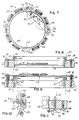
- FIG. 7 is a top plan view of a stator of an alternator assembly for an internal combustion engine according to an example of the present invention, wherein the components of a regulator are contained on a bracket mounted on the stator;
- FIG. 8 is a fragmentary side view in elevation of the bracket and regulator components illustrated in FIG. 7;
- FIG. 9 is a side view in elevation of an alternate bracket assembly for the example of FIG. 7;
- FIG. 10 is a top plan view of the stator of an alternator assembly for an internal combustion engine according to another example of the present invention, incorporating a regulator in the form of a circuit board;
- FIG. 11 is an enlarged fragmentary side view illustrating the mounting of the circuit board illustrated in FIG. 10 to the stator.
- Referring now to the drawings, FIG. 1 illustrates a stator generally designated by the
numeral 1 of an alternator assembly for an internal combustion engine (not shown). It should specifically be understood that the term "alternator assembly" as used herein encompasses not only alternators but also generators used in connection with internal combustion engines. Additionally, although FIG. 1 illustrates one design of a stator employed with such an alternator assembly, it is to be understood that FIG. 1 is illustrative of only one such design. -
Stator 1 includes a stationaryannular ring member 2 having an inner surface 3 and an outer surface 4.Stator 1 is typically mounted in a stationary position disposed concentric with the axis of rotation of an engine's crankshaft (not shown). As shown best in FIG. 1,stator 1 includes a plurality of spaced windings orwire coils 5 arranged circumferentially about outer surface 4.Coils 5 cooperate in the conventional manner with a moving magnetic field for producing an electric output current therein. The magnetic field is typically provided by a plurality of rotating magnets 6 (only one of which is shown in FIG. 1) arranged in opposing relation towire coils 5 and disposed concentric therewith. As shown best in FIG. 1, rotating magnets 6 are mounted on an inner surface 7 of rotating flywheel 8 (shown in phantom lines). Flywheel 8 is connected to the engine's crankshaft in any conventional manner and typically is in the shape of a cup so that magnets 6 may be disposedopposite wire coils 5, as is conventional.Stator 1 also includes fourlands 9 projecting from outer surface 4 and integral therewith which provide a means for mountingstator 1 in a stationary position on the engine by means ofscrews 10. - Referring now to FIG. 3, the alternator assembly includes a regulator whose schematic circuitry is designated by the
numeral 11.Regulator 11 may be of any conventional design, and may be in the form of discrete components (FIG. 3) or integrated circuit chips (FIG.4).Regulator 11, as illustrated in FIG. 3, is for illustrative purposes only, and illustrates a schematic diagram for a half wave regulator/stator circuit incorporating a charge indicator circuit, which is an optional add-on circuit in many regulator circuits. More particularly, FIG. 3 illustrates circuit means including a plurality of discrete components connected to awire coil 5 to regulate the output current therein. More specifically, the discrete components include a one hundred volt twelve ampRMS SCR device 12 connected to one terminal ofcoil 5 together with a one amp, six hundredvolt diode 13, a second one amp six hundredvolt diode 14 and a fourteen volt, onewatt zener diode 15 connected to the other terminal ofcoil 5. Additionally, a one hundred ohm onewatt resistor 25 is connected acrossSCR 12 anddiode 13 so as to be connected on one side between the anode ofSCR 12 andcoil 5 and its other side betweendiode 13 anddiode 14. As noted previously, the circuit illustrated in FIG. 3 is conventional and described for illustrative purposes only since other designs are possible. One such alternate design is illustrated in FIG. 4 where a portion of the discrete components of the regulator circuit of FIG. 3 has been replaced by integrated circuit chips 16 and 26 mounted inreceptacles - Referring now to FIG. 2, there is illustrated the manner in which the components of
regulator 11 are mounted directly onstator 1. As illustrated, components 12-15 and 25 are arranged longitudinally with respect to one another and mounted so as to engage or bear against outer surface 4 ofstator 1. In order to securely mount the components ofregulator 11 onstator 1, one end of the regulator circuit is attached to aterminal 17 which in turn is mounted to one of thelands 9 by means of ascrew fastener 18. The other end comprising the tab ofSCR 12 of the regulator circuit is similarly mounted to anotherland 9 by ascrew fastener 20. An adhesive such as anepoxy resin 21 may also be employed with or withoutfasteners regulator 11 tostator 1. Epoxy 21 not only adhesively attaches the components ofregulator 11 to outer surface 4 ofstator 1, but also eliminates vibration of the various components so as to prevent vibration breakage of the components or wires there-between. - As illustrated in FIG. 3,
regulator 11 includes apolarized plug 22 for connecting the output current fromcoils 5 to acharge indicator bulb 24 which is controlled in a conventional manner by a charge indicator circuit 19. Circuit 19 is a standard optional add-on circuit readily available from numerous sources such as Wells Corp. or Tympanium Corp., as is well known in the art.Plug 22 is polarized to prevent improper connections. Thus,plug 22 represents the only external connection fromstator 1. As is typical, the output current fromcoils 5 as regulated byregulator 11, may be employed to provide battery charging current and therefore one terminal of the two connector plug leads tobattery 23. The other terminal ofplug 22 feeds directly to chargingindicator bulb 24. Other accessories such asheadlamp 29 can be connected directly to thebattery 23 or connected through aswitch 30. - It should be noted that other engine monitoring circuits may also be mounted directly on
stator 1 in addition toregulator circuit 11. Such circuits may include, for example, safety interlock circuits, oil pressure start circuits, tachometer circuits, engine hour metering circuits, overheat circuits, and other similar circuitry. Safety interlock circuits are well known in the art and include those that kill the engine of a lawn mower upon releasing the bail of a walk behind mower or upon getting off the seat of a riding mower. A typical example is shown in Kronich et al U.S. Patent No. 4,394,893. Oil pressure start circuits are also well known in the art and include those that kill the engine upon sensing low oil pressure, but allow restarting when normal oil pressure is sensed. Tachometer circuits are also well known and typically comprise those that sense and display engine speed. Engine hour metering circuits are well known and are used to count and display the number of hours an engine has actually been in operation. Finally, overheat circuits are also well known and are typically used to shut down or kill an engine or turn on a warning red light when an engine runs hotter than a desired temperature. - Referring now to FIG. 5, there is illustrated a schematic diagram for a full wave regulator/stator circuit. More particularly, FIG. 5 illustrates circuit means including a plurality of discrete components connected to a wire coil 40 which will regulate the output current therein. The discrete components include a 100
volt 12 ampRMS SCR device 41 connected to one terminal of coil 40 with a 1 amp, 600 volt diode 42, a second 1 amp 600 volt diode 43 and a 14 volt, 1watt zener diode 44 connected to ground. Additionally, a 100ohm 1watt resistor 45 is connected acrossSCR 41 and diode 42 so as to connect it on one side between the anode ofSCR 41 and coil 40 on its other side between diode 42 and diode 43. An identical circuit to the one just described is connected to the opposite terminal of coil 40 and includes anSCR 46,diodes 47 and 48,zener diode 49 andresistor 50. As noted previously, the circuit illustrated in FIG. 5 is conventional and described for illustrated purposes only since other designs are possible. - Referring now to FIG. 6, there is illustrated another circuit diagram for an alternate full wave regulator/stator circuit. More particularly, FIG. 6 illustrates circuit means including a plurality of discrete components connected to a
wire coil 51 to regulate the output current therein. More specifically, the discrete components include the identical half wave circuit described above with respect to FIG. 5 connected to one terminal ofcoil 51 which includesSCR 51,diodes 53 and 54,zener diode 55 andresistor 56. Likewise, an identical half wavecircuit comprising SCR 57,diodes 58 and 59, zener diode 60 andresistor 61 as connected to the other terminal ofcoil 51. Additionally, the cathodes ofSCR devices diodes - Referring now to FIG. 7, there is illustrated a
stator 64 identical in structure tostator 1 of FIG. 1.Stator 64 includes a stationaryannular ring member 65 having an innerradial surface 66 and an outerradial surface 67.Ring member 65 also includes an upstandingannular flange 68 which defines a cylindrical plane designated by the numeral 69 which is disposed concentric with the axis of rotation of an engine's crankshaft (not shown).Stator 64 also includes fourlands 70 projecting radially outwardly fromsurface 67 that are integral withring member 65 which provide a means for mountingstator 64 in a stationary position, and provide a means for mounting a regulator circuit onstator 64. In this embodiment, the regulator circuit is in the form of discrete components arranged to be connected to thecentral portion 71 of abracket 72. As shown best in FIG. 8,bracket 72 includescentral portion 71 integrally connected to a pair of L-shapedend members screws end members bracket 72 onstator 64. As best seen in FIG. 7,end members central portion 71 so thatcentral portion 71 and the components of the regulator circuit are located radially inwardly ofcylindrical plane 69 yet the mounting forbracket 72 is radially outwardly ofcylindrical plane 69. - FIG. 9 illustrates an alternate method of mounting the components of a regulator circuit on
stator 64. In this embodiment, thebracket 77 extends betweenadjacent lands 70 and is spaced upwardly from the top surfaces oflands 70 so as to extend over the top edge offlange 68 by means of a pair ofspacers spacer bracket 77 and is adapted to receive ascrew 80 or 81 extending therethrough for mountingbracket 77 onstator 64. Once again, the components of the regulator circuit are located withincylindrical plane 69 with thebracket 77 mounted outside ofplane 69. - Referring now to FIG. 10, there is illustrated another method of mounting a regulator circuit to a
stator 82.Stator 82 once again is identical tostators circuit board 83. Thecircuit board 83, in turn, is mounted onstator 82 by means ofSCR device 84.SCR device 84 may be any of the SCR devices previously described herein i.e.devices SCR device 84 includes a plurality ofterminals 85 extending through circuit board 93 and soldered thereto in the conventional manner.SCR device 84 also includes a mountingplate 86 attached to one side thereof including anopening 87 formed therethrough for receiving ascrew 88 for mountingboard 83 on one of fourlands 89 projecting fromstator 82. Thus, as best shown in FIG. 10,circuit board 83 and components of the regulator circuit are located radially inwardly ofcylindrical plane 90 while the actual mounting assembly is located radially outwardly ofplane 90.
Claims (7)
- An alternator assembly for an internal combustion engine, comprising:
stator means (64 or 82) including at least one coil means (5) cooperable with a moving magnetic field created by magnets (6) on a rotatable flywheel (8) for producing an electric output current in said coil means and a stationary annular ring member (65) having an inner radial surface (66) and an outer radial surface (67) defining a cylindrical plane (69 or 90);
engine circuit means (11) for monitoring a desired engine parameter; and
mounting means for mounting said engine circuit means on said stator means, characterised in that:
said mounting means includes a bracket (72 or 77 or 86) supporting said engine circuit means so that the mounting of said bracket is radially outwards of said cylindrical plane and components of said engine circuit means are located radially inwardly of said cylindrical plane. - An alternator assembly according to claim 1, wherein said engine circuit means comprises a regulator circuit (11) connected to said coil means (5) for regulating said output current.
- An alternator assembly according to claim 1 or 2, wherein said engine circuit means comprises a safety interlock circuit.
- An alternator assembly according to any preceding claim, wherein said engine circuit means comprises an oil pressure start circuit.
- An alternator assembly according to any preceding claim, wherein said engine circuit means comprises a tachometer circuit.
- An alternator assembly according to any preceding claim, wherein said engine circuit means comprises an engine hour metering circuit.
- An alternator assembly according to any preceding claim, wherein said engine circuit means comprises an engine overheat circuit.
Applications Claiming Priority (2)
| Application Number | Priority Date | Filing Date | Title |
|---|---|---|---|
| US07/506,470 US5031587A (en) | 1989-03-22 | 1990-04-09 | Internal combustion engine with integral stator and regulator |
| US506470 | 1990-04-09 |
Publications (2)
| Publication Number | Publication Date |
|---|---|
| EP0452037A1 EP0452037A1 (en) | 1991-10-16 |
| EP0452037B1 true EP0452037B1 (en) | 1993-08-11 |
Family
ID=24014732
Family Applications (1)
| Application Number | Title | Priority Date | Filing Date |
|---|---|---|---|
| EP91302964A Expired - Lifetime EP0452037B1 (en) | 1990-04-09 | 1991-04-04 | An alternator assembly for an internal combustion engine |
Country Status (5)
| Country | Link |
|---|---|
| US (1) | US5031587A (en) |
| EP (1) | EP0452037B1 (en) |
| JP (1) | JPH0591703A (en) |
| CA (1) | CA2040006A1 (en) |
| DE (1) | DE69100245T2 (en) |
Families Citing this family (13)
| Publication number | Priority date | Publication date | Assignee | Title |
|---|---|---|---|---|
| IT1279098B1 (en) * | 1995-01-10 | 1997-12-04 | Bitron Spa | IMPROVEMENTS TO BRUSHLESS MOTORS, IN PARTICULAR FOR DIRECT DRIVING OF THE WASHING MACHINE BASKET |
| JP3508363B2 (en) * | 1995-05-11 | 2004-03-22 | 株式会社デンソー | Power supply system for vehicles |
| US6091231A (en) * | 1997-06-19 | 2000-07-18 | R. E. Phelon Company, Inc. | Alternator assembly |
| US6089214A (en) * | 1998-11-02 | 2000-07-18 | United States Clean Air Company (Llc) | Engine spark ignition system capacitive coupler |
| GB0109179D0 (en) * | 2001-04-12 | 2001-05-30 | Alstom | Improvements relating to rotary electrical machines |
| US6818825B2 (en) * | 2002-08-13 | 2004-11-16 | Briggs & Stratton Corporation | Regulator connector assembly for small engine |
| KR100803570B1 (en) * | 2006-06-20 | 2008-02-15 | 엘지전자 주식회사 | Axial Airflow Motor |
| US20080218035A1 (en) * | 2007-03-09 | 2008-09-11 | C.E. Niehoff & Co. | Rotating rectifier assembly |
| GB2473243B (en) * | 2009-09-07 | 2013-08-21 | Rolls Royce Plc | Control assembly |
| CN102826237B (en) * | 2012-09-13 | 2015-03-04 | 郑州大学 | Repeatable locking device for magnetically levitated flywheel |
| CN104309821A (en) * | 2014-09-29 | 2015-01-28 | 北京石油化工学院 | Repeatable maglev flywheel locking device |
| CN104899399B (en) * | 2015-06-24 | 2018-01-12 | 北京石油化工学院 | The design method of repeatable electromagnetic locking device electromagnet |
| CN104899400B (en) * | 2015-06-24 | 2018-02-23 | 北京石油化工学院 | The repeatable design method for embracing formula locking device shell fragment of magnetically levitated flywheel |
Family Cites Families (4)
| Publication number | Priority date | Publication date | Assignee | Title |
|---|---|---|---|---|
| US2427573A (en) * | 1943-10-12 | 1947-09-16 | Wico Electric Co | Magneto |
| US3673490A (en) * | 1970-09-29 | 1972-06-27 | Phelon Co Inc | Combined alternator and ignition trigger signal generator with arrangement for suppressing spurious trigger signals |
| SE425423B (en) * | 1978-06-02 | 1982-09-27 | Svenska Electromagneter | DEVICE FOR ELECTRONIC IGNITION SYSTEMS, PREFERRED TO COMBUSTION ENGINES |
| US4915068A (en) * | 1989-03-22 | 1990-04-10 | Briggs & Stratton Corporation | Internal combustion engine with integral stator and regulator |
-
1990
- 1990-04-09 US US07/506,470 patent/US5031587A/en not_active Expired - Fee Related
-
1991
- 1991-04-04 EP EP91302964A patent/EP0452037B1/en not_active Expired - Lifetime
- 1991-04-04 DE DE91302964T patent/DE69100245T2/en not_active Expired - Fee Related
- 1991-04-08 JP JP3075409A patent/JPH0591703A/en active Pending
- 1991-04-08 CA CA002040006A patent/CA2040006A1/en not_active Abandoned
Also Published As
| Publication number | Publication date |
|---|---|
| DE69100245D1 (en) | 1993-09-16 |
| DE69100245T2 (en) | 1994-02-10 |
| JPH0591703A (en) | 1993-04-09 |
| CA2040006A1 (en) | 1991-10-10 |
| US5031587A (en) | 1991-07-16 |
| EP0452037A1 (en) | 1991-10-16 |
Similar Documents
| Publication | Publication Date | Title |
|---|---|---|
| US5031587A (en) | Internal combustion engine with integral stator and regulator | |
| US6198191B1 (en) | Brush assembly for an alternator | |
| EP0731550B1 (en) | AC generator for use in a vehicle | |
| US4873962A (en) | High efficiency electrical alternator system | |
| US4915068A (en) | Internal combustion engine with integral stator and regulator | |
| EP1649099A1 (en) | Cleaning wipe and method of manufacture | |
| EP2608342A1 (en) | Overvoltage Protection System and Method | |
| US20060186747A1 (en) | Protective cover which is intended to be mounted on the rear bearing of a rotating electrical machine, alternator and alternator-starter comprising one such cover | |
| US3378708A (en) | Alternators | |
| US3962621A (en) | Dual battery charging generator system | |
| CN100523484C (en) | Vehicle distributor, module of vehicle ignition system and method | |
| US6707691B2 (en) | Compact rectifier bridge and method for manufacturing the same | |
| US20050258693A1 (en) | Permanent magnet alternator and voltage regulator for regulating the output voltage of a permanent magnet alternator | |
| US3875438A (en) | Small engine auxiliary electrical system | |
| US6483277B1 (en) | Common pin voltage regulator | |
| JP2002136076A (en) | Alternator | |
| US4172230A (en) | Electrical connectors for magneto stator | |
| US20040256925A1 (en) | Rectifier for a vehicle alternator | |
| EP0428301A1 (en) | Integral stator and rectifier for internal combustion engines | |
| US4746825A (en) | Alternator core attachment | |
| USRE40320E1 (en) | Permanent magnet alternator and voltage regulator circuit for the permanent magnet alternator | |
| US20250112518A1 (en) | Electric mower and mowing deck motor assembly | |
| JPH0717263Y2 (en) | Vehicle AC generator voltage regulator | |
| USRE28145E (en) | Tharman rectifier network assembly | |
| Heller | Truck Electrical Systems |
Legal Events
| Date | Code | Title | Description |
|---|---|---|---|
| PUAI | Public reference made under article 153(3) epc to a published international application that has entered the european phase |
Free format text: ORIGINAL CODE: 0009012 |
|
| AK | Designated contracting states |
Kind code of ref document: A1 Designated state(s): DE FR GB IT |
|
| 17P | Request for examination filed |
Effective date: 19920408 |
|
| 17Q | First examination report despatched |
Effective date: 19920605 |
|
| GRAA | (expected) grant |
Free format text: ORIGINAL CODE: 0009210 |
|
| AK | Designated contracting states |
Kind code of ref document: B1 Designated state(s): DE FR GB IT |
|
| REF | Corresponds to: |
Ref document number: 69100245 Country of ref document: DE Date of ref document: 19930916 |
|
| ET | Fr: translation filed | ||
| ITF | It: translation for a ep patent filed | ||
| PLBE | No opposition filed within time limit |
Free format text: ORIGINAL CODE: 0009261 |
|
| STAA | Information on the status of an ep patent application or granted ep patent |
Free format text: STATUS: NO OPPOSITION FILED WITHIN TIME LIMIT |
|
| 26N | No opposition filed | ||
| PGFP | Annual fee paid to national office [announced via postgrant information from national office to epo] |
Ref country code: GB Payment date: 19950327 Year of fee payment: 5 |
|
| PGFP | Annual fee paid to national office [announced via postgrant information from national office to epo] |
Ref country code: DE Payment date: 19950410 Year of fee payment: 5 |
|
| PGFP | Annual fee paid to national office [announced via postgrant information from national office to epo] |
Ref country code: FR Payment date: 19950411 Year of fee payment: 5 |
|
| PG25 | Lapsed in a contracting state [announced via postgrant information from national office to epo] |
Ref country code: GB Effective date: 19960404 |
|
| GBPC | Gb: european patent ceased through non-payment of renewal fee |
Effective date: 19960404 |
|
| PG25 | Lapsed in a contracting state [announced via postgrant information from national office to epo] |
Ref country code: FR Effective date: 19961227 |
|
| PG25 | Lapsed in a contracting state [announced via postgrant information from national office to epo] |
Ref country code: DE Effective date: 19970101 |
|
| REG | Reference to a national code |
Ref country code: FR Ref legal event code: ST |
|
| K1C1 | Correction of patent application (title page) published |
Effective date: 19911016 |
|
| PG25 | Lapsed in a contracting state [announced via postgrant information from national office to epo] |
Ref country code: IT Free format text: LAPSE BECAUSE OF NON-PAYMENT OF DUE FEES;WARNING: LAPSES OF ITALIAN PATENTS WITH EFFECTIVE DATE BEFORE 2007 MAY HAVE OCCURRED AT ANY TIME BEFORE 2007. THE CORRECT EFFECTIVE DATE MAY BE DIFFERENT FROM THE ONE RECORDED. Effective date: 20050404 |