EP0451828A2 - Recording apparatus - Google Patents
Recording apparatus Download PDFInfo
- Publication number
- EP0451828A2 EP0451828A2 EP91105708A EP91105708A EP0451828A2 EP 0451828 A2 EP0451828 A2 EP 0451828A2 EP 91105708 A EP91105708 A EP 91105708A EP 91105708 A EP91105708 A EP 91105708A EP 0451828 A2 EP0451828 A2 EP 0451828A2
- Authority
- EP
- European Patent Office
- Prior art keywords
- recording
- recording apparatus
- passage
- ink
- ink jet
- Prior art date
- Legal status (The legal status is an assumption and is not a legal conclusion. Google has not performed a legal analysis and makes no representation as to the accuracy of the status listed.)
- Granted
Links
Images

Classifications
-
- F—MECHANICAL ENGINEERING; LIGHTING; HEATING; WEAPONS; BLASTING
- F16—ENGINEERING ELEMENTS AND UNITS; GENERAL MEASURES FOR PRODUCING AND MAINTAINING EFFECTIVE FUNCTIONING OF MACHINES OR INSTALLATIONS; THERMAL INSULATION IN GENERAL
- F16M—FRAMES, CASINGS OR BEDS OF ENGINES, MACHINES OR APPARATUS, NOT SPECIFIC TO ENGINES, MACHINES OR APPARATUS PROVIDED FOR ELSEWHERE; STANDS; SUPPORTS
- F16M13/00—Other supports for positioning apparatus or articles; Means for steadying hand-held apparatus or articles
- F16M13/005—Other supports for positioning apparatus or articles; Means for steadying hand-held apparatus or articles integral with the apparatus or articles to be supported
-
- B—PERFORMING OPERATIONS; TRANSPORTING
- B41—PRINTING; LINING MACHINES; TYPEWRITERS; STAMPS
- B41J—TYPEWRITERS; SELECTIVE PRINTING MECHANISMS, i.e. MECHANISMS PRINTING OTHERWISE THAN FROM A FORME; CORRECTION OF TYPOGRAPHICAL ERRORS
- B41J11/00—Devices or arrangements of selective printing mechanisms, e.g. ink-jet printers or thermal printers, for supporting or handling copy material in sheet or web form
- B41J11/0045—Guides for printing material
- B41J11/005—Guides in the printing zone, e.g. guides for preventing contact of conveyed sheets with printhead
-
- B—PERFORMING OPERATIONS; TRANSPORTING
- B41—PRINTING; LINING MACHINES; TYPEWRITERS; STAMPS
- B41J—TYPEWRITERS; SELECTIVE PRINTING MECHANISMS, i.e. MECHANISMS PRINTING OTHERWISE THAN FROM A FORME; CORRECTION OF TYPOGRAPHICAL ERRORS
- B41J11/00—Devices or arrangements of selective printing mechanisms, e.g. ink-jet printers or thermal printers, for supporting or handling copy material in sheet or web form
- B41J11/48—Apparatus for condensed record, tally strip, or like work using two or more papers, or sets of papers, e.g. devices for switching over from handling of copy material in sheet form to handling of copy material in continuous form and vice versa or point-of-sale printers comprising means for printing on continuous copy material, e.g. journal for tills, and on single sheets, e.g. cheques or receipts
-
- B—PERFORMING OPERATIONS; TRANSPORTING
- B41—PRINTING; LINING MACHINES; TYPEWRITERS; STAMPS
- B41J—TYPEWRITERS; SELECTIVE PRINTING MECHANISMS, i.e. MECHANISMS PRINTING OTHERWISE THAN FROM A FORME; CORRECTION OF TYPOGRAPHICAL ERRORS
- B41J13/00—Devices or arrangements of selective printing mechanisms, e.g. ink-jet printers or thermal printers, specially adapted for supporting or handling copy material in short lengths, e.g. sheets
- B41J13/10—Sheet holders, retainers, movable guides, or stationary guides
- B41J13/12—Sheet holders, retainers, movable guides, or stationary guides specially adapted for small cards, envelopes, or the like, e.g. credit cards, cut visiting cards
-
- B—PERFORMING OPERATIONS; TRANSPORTING
- B41—PRINTING; LINING MACHINES; TYPEWRITERS; STAMPS
- B41J—TYPEWRITERS; SELECTIVE PRINTING MECHANISMS, i.e. MECHANISMS PRINTING OTHERWISE THAN FROM A FORME; CORRECTION OF TYPOGRAPHICAL ERRORS
- B41J29/00—Details of, or accessories for, typewriters or selective printing mechanisms not otherwise provided for
- B41J29/02—Framework
-
- B—PERFORMING OPERATIONS; TRANSPORTING
- B41—PRINTING; LINING MACHINES; TYPEWRITERS; STAMPS
- B41J—TYPEWRITERS; SELECTIVE PRINTING MECHANISMS, i.e. MECHANISMS PRINTING OTHERWISE THAN FROM A FORME; CORRECTION OF TYPOGRAPHICAL ERRORS
- B41J3/00—Typewriters or selective printing or marking mechanisms characterised by the purpose for which they are constructed
- B41J3/36—Typewriters or selective printing or marking mechanisms characterised by the purpose for which they are constructed for portability, i.e. hand-held printers or laptop printers
-
- F—MECHANICAL ENGINEERING; LIGHTING; HEATING; WEAPONS; BLASTING
- F16—ENGINEERING ELEMENTS AND UNITS; GENERAL MEASURES FOR PRODUCING AND MAINTAINING EFFECTIVE FUNCTIONING OF MACHINES OR INSTALLATIONS; THERMAL INSULATION IN GENERAL
- F16M—FRAMES, CASINGS OR BEDS OF ENGINES, MACHINES OR APPARATUS, NOT SPECIFIC TO ENGINES, MACHINES OR APPARATUS PROVIDED FOR ELSEWHERE; STANDS; SUPPORTS
- F16M11/00—Stands or trestles as supports for apparatus or articles placed thereon Stands for scientific apparatus such as gravitational force meters
- F16M11/20—Undercarriages with or without wheels
- F16M11/22—Undercarriages with or without wheels with approximately constant height, e.g. with constant length of column or of legs
-
- F—MECHANICAL ENGINEERING; LIGHTING; HEATING; WEAPONS; BLASTING
- F16—ENGINEERING ELEMENTS AND UNITS; GENERAL MEASURES FOR PRODUCING AND MAINTAINING EFFECTIVE FUNCTIONING OF MACHINES OR INSTALLATIONS; THERMAL INSULATION IN GENERAL
- F16M—FRAMES, CASINGS OR BEDS OF ENGINES, MACHINES OR APPARATUS, NOT SPECIFIC TO ENGINES, MACHINES OR APPARATUS PROVIDED FOR ELSEWHERE; STANDS; SUPPORTS
- F16M2200/00—Details of stands or supports
- F16M2200/08—Foot or support base
Definitions
- the present invention relates to a recording apparatus for recording onto a recording sheet based on image information.
- a recording apparatus such as a printer, a copying machine and a facsimile terminal equipment is constituted to record an image consisting of dot patterns onto a sheet-like recording medium (thereafter referred to as a recording sheet) such as paper or plastic thin board, by driving energy generation means of recording head, based on image information.
- a recording sheet such as paper or plastic thin board
- the recording apparatus can be classified into the ink jet printing, wire dot-matrix printing, thermal recording and laser beam printing systems, according to the method or recording.
- a recording sheet useful for recording there is a thick paper such as an envelope or postcard, or a special sheet such as a plastic thin board, as well as a plain paper.
- the recording apparatus which is generally a horizontal type, has an insertion opening and an exhaustion opening for recording sheet which are provided on an upper face of recording apparatus.
- a recording sheet inserted through the insertion opening is recorded while being conveyed along a recording sheet conveyance passage constructed as a U-shape, and then exhausted through the exhaustion opening after recording.
- a recording apparatus in which an insertion opening for thick paper or special sheet is provided on an under face of apparatus to make its conveyance passage straight-like, whereby recording sheet such as a thick paper can be also conveyed smoothly.
- the insertion opening for recording sheet is provided on upper and lower (bottom) faces, and the exhaustion opening for recording sheet is provided on an upper face.
- the recording apparatus having the insertion opening for recording sheet on upper and lower faces has two service conditions (attitudes), i.e., horizontal and vertical, depending on the insertion direction of recording sheet, and in order to be stable in either condition, an external shape of recording apparatus must be almost cube with the approximately same depth and height, resulting in a waste space in the interior.
- the recording apparatus like a printer useful as an output apparatus is also demanded to be made small-sized and at lower cost.
- An object of the present invention is to provide a recording apparatus which allows the externals to be smaller.
- Another object of the present invention is to provide a recording apparatus with a simple structure and lower cost.
- Another object of the present invention is to provide a recording apparatus which can deal with a special recording sheet such as a thick paper and can make the excellent recording.
- Another object of the present invention is, in view of the aforementioned technical problems, to provide a recording apparatus which can be used stably in either of the horizontal and vertical conditions, and allows the miniaturization of externals, simplification of structure, and reduction of cost.
- Another object of the present invention is to provide a recording apparatus for recording onto a recording sheet based on image information, wherein the recording apparatus can be used stably in either of the horizontal and vertical conditions, and allows the miniaturization of externals, simplification of structure, and reduction of cost, by providing an insertion opening for recording sheet on the identical and opposite sides to an exhaustion opening for recording sheet and providing a rotatable support saddle on a back portion of the recording apparatus.
- Another object of the present invention is to provide an ink jet recording apparatus using an ink jet recording head and having a battery mechanism, which can maintain the stable service condition, wherein it is constituted to have a rotatable support saddle on an external surface of recording apparatus on the hand of battery mechanism storage portion so as to place the center of gravity substantially and surely in a lower location in the vertical service condition.
- Another object of the present invention is to provide an ink jet recording apparatus having an ink jet recording head and a battery mechanism, wherein it can perform the stable recording in either of the vertical and horizontal service conditions for the apparatus, by providing a support saddle on the hand of battery mechanism thereby to resolve misoperation problem resulting from the advantage of having no limitations in the service condition of ink jet recording head.
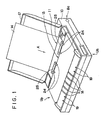
- Fig. 1 is a perspective view showing one example of a recording apparatus to which the present invention is applied, in the horizontal service condition.
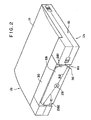
- Fig. 2 is a perspective view showing a back portion of the recording apparatus as shown in Fig. 1, during the non-recording.
- Fig. 3 is a perspective view showing the recording apparatus as shown in Fig. 1, in the vertical service condition.
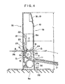
- Fig. 4 is a longitudinal cross-sectional view showing the apparatus as shown in Fig. 3, in the vertical service condition.
- Fig. 1 is a perspective view showing a recording apparatus 10 according to one example of the present invention, in the horizontal service condition
- Fig. 2 is a perspective view showing a back portion of the recording apparatus 10 as shown in Fig. 1.
- Fig. 3 is a perspective view showing the recording apparatus 10 as shown in Fig. 1, in the vertical service condition.
- Fig. 4 is a longitudinal cross-sectional view showing an internal construction of the apparatus 10 as shown in Fig. 3, in the vertical service condition.
- the recording apparatus 10 is an ink jet recording apparatus with the ink jet recording method for recording an image onto a recording sheet 14 by discharging the ink through discharge ports of a recording head by the use of electricity-heat converters for forming ink liquid droplets.
- the recording apparatus 10 of this example is normally used in the horizontal service condition (as shown in Fig. 1), while in the vertical condition, it is used in the standing attritude with a back portion Ba being placed on the under face and an upper face Up as the front face.
- a first insertion opening for recording sheet 11 and an exhaustion opening for recording sheet 13 are provided on the upper face Up of the recording apparatus 10.
- a recording sheet 14 inserted through the first insertion opening for recording sheet 11 is closely carried on a peripheral surface of platen roller 14 (Fig. 4) which is also used as sheet feed roller, and conveyed in the direction of the arrow A along a first recording sheet conveyance passage S1. That is, as shown in Fig. 4, the recording sheet manually inserted from an upper cover 17b through the sheet insertion opening 11 is conveyed by the platen roller 15 and exhausted through the sheet exhaustion opening 13.
- the above mentioned recording sheet 14 inserted through the sheet insertion opening 11 passes through a position opposed to recording head 16 (Fig. 4), where an image is recorded by the recording head 16, and is exhausted upward (forward in the vertical type) through the sheet exhaustion opening 13 after recording.
- the upper cover 17 is fitted, in an openable or closable manner, into place on an upper face of the recording apparatus 10, wherein it is used as a paper feed tray or exhaustion tray in an open state during recording, as shown in Fig. 1, and is set to a closed position during non-recording (reverse or storage) as shown in Fig. 2.
- the upper cover 17 has a feature of covering and protecting an upper face Up of recording apparatus 10 in the closed state, in which the first recording sheet insertion opening 11, the recording sheet exhaustion opening 13, switches 18, a display 19 and so on are disposed.
- the recording head 16 is mounted on a carriage 22 movable in a reciprocatory motion along guide shafts 20, 21 parallel to the platen roller 15.
- the recording head as shown in an instance of ink jet recording head, in which an ink tank for storing the ink and the head are integrally formed as an exchangeable head cartridge for the recording apparatus 10. Also, the recording head 16 may be formed separately from the ink tank.
- the ink jet recording head 16 is a recording head for discharging the ink by the use of the heat energy with electricity-heat converters for generating the heat energy.
- the ink jet recording head 16 makes the recording by discharging the ink through the discharge ports by growth of bubbles owing to film boiling caused by the heat energy applied by the electricity-heat converters.
- a sheet presser plate 23 for pressing a recording sheet 14 against the platen roller 15 is placed upstream of the recording head 16 in the conveyance direction, and elastically biased onto a periphery of platen roller 15 by means of a spring 35 provided between main body of apparatus and the presser plate 23.
- a spur 24 having teeth around its periphery and an exhaustion roller 25 to aid in the exhaustion of recording sheet 14 are disposed in the recording sheet exhaustion opening 13.
- a second recording sheet insertion opening 12 is provided on the rear face Un (back face in the vertical condition) of the recordings apparatus 10. And a second recording sheet conveyance passage S2 is formed in substantially straight shape, leading from the recording sheet insertion opening 12 through a recording portion R between the recording head 16 and the platen roller 15 to the recording sheet exhaustion opening 13.
- This second recording sheet conveyance passage S2 can easily feed a nervy recording sheet 26, such as a thick recording sheet such as a postcard or envelope, or a special recording sheet as a plastic sheet, because of its substantially straight shape
- the recording sheet or special recording sheet 26 is inserted in the direction of the arrow B as indicated in Fig. 3, passed through the recording portion R, exhausted out of the recording sheet exhaustion opening 13, and stacked onto a paper exhaustion tray formed by the upper cover 17 placed in the open state around an axis 17a.
- a support saddle 28 is mounted to be rotatable (for storage and overhang) on a back portion Ba (or an under face Un in the vertical attitude shown in Figs. 3 and 4) of the recording apparatus 10.
- the support saddle 28 is rotatably mounted around an axis 29 within a recess 36 depressed by almost a thickness of support saddle 28 which is provided on the back portion Ba.
- the support saddle 28 When the recording apparatus 10 is used in the vertical attitude, the support saddle 28 is rotated to the overhang position where it is approximately orthogonal to the body of recording apparatus 10. Thereby, the recording apparatus 10 can be stably supported in the vertical attitude, and can be placed in a stale condition for inserting the recording sheet 14, or operating the switches 18.
- the support saddle 28 is rotated into a withdrawal position almost parallel to the recording apparatus 10, as shown in Fig. 2, so that the support saddle 28 can be set to the state where it is no obstacle to the recording apparatus 10 in the horizontal attitude, thereby not impeding the storage or transport.
- the support saddle 28 provided on the back portion Ba of recording apparatus 10 serves as a backup for a battery cover 30 for carrying a battery 27 contained in the back portion Ba of the apparatus, so that the battery cover 30 detachable from the main body can not be easily disengaged owing to the vibration or impact.
- the battery 27 when using an ink jet recording head 16, the battery 27 is served as a driving source for the heat driving of the ink jet recording head 16 or the serial reciprocation driving in recording, or recovery means for performing well-known head recovery processsing such as suction or pressure recovery, cleaning, etc., in accordance with the timer for deciding the non-use period or its decision result, when the apparatus is left away for a long time or intermittently used.
- the battery 27 may be a battery mechanism such as an accumulator or solar battery as well as battery.
- this example is a recording apparatus using the ink jet recording head 16 and the battery mechanism 27, wherein in the horizontal service condition, the battery mechanism 27 is arranged to place its large surface (back portion Un) of almost rectangular parallelopiped on the bottom face, as seen from Fig. 2, so that the apparatus can be used stably without substantially changing the center of gravity.
- the support saddle 28 provided in the vicinity of the battery mechanism as seen from Fig. 4, an operator can use the apparatus with the support saddle 28 placed on the bottom without false operation, whereby the recording is performed with the center of gravity being necessarily placed in a lower part of the apparatus 10.
- the support saddle 28 serves to put the apparatus into an extremely stable state due to the cooperation with the battery mechanism 27.
- end portions 281, 282 of support saddle 28 in the longitudinal direction are shaped like circular arcs, as shown in Fig. 2. This contour is intended to distribute evenly the load applied thereto from the external and absorb it all over the surface of support saddle 28.
- This circular arc shape is one in which the end portion 282 is a circular arc with the radius R1, and the end portion 281 with the radius R2, with the center of rotation in the support saddle 28.
- the rotatable support saddle 28 is preferably made of the same material as that for the main body of apparatus, and it is more preferred that in the vertical service condition, the support saddle is held in position crosswise to the apparatus body on the central portion thereof, while in the horizontal service condition, it is held in position of being substantially accommodated within an external face of the apparatus body.
- a well-known stop mechanism is used in which a combination of a rib for stopping the rotation and a rib which is ridden over by the support saddle but serves as a stop with a slight amount of working force or a hook mechanism is applicable.
- Fig. 4 above the support saddle 28 forming the under face, there is shown the battery mechanism 27, above which are located a conveyance mechanism such as platen roller 15, and further the ink jet recording head 16 in a downwardly directed recording form (for discharging the ink downwardly), with the center C of the apparatus body 10 with height 2L being located at the ink tank 16a for recording head 16.
- the ink jet recording head 16 when the ink jet recording head 16 is formed as a disposable or replaceable type, the amount of ink storage within the ink tank 16a is decreased during the consumption for recording, while most of the weight of whole apparatus is located lower than the center C, so that the vertical service condition can be made more stably.
- the recording sheet insertion openings 11, 12 are provided on an upper face Up and an under face Un of recording apparatus 10, and the recording sheet exhaustion opening 13 is provided on the upper face Up of recording apparatus 10. Also, the recording sheet insertion openings 11, 12 are provided on the identical and opposite faces to the recording sheet exhaustion opening 13, respectively, and the rotatable support saddle 28 is provided on a back portion of the recording apparatus 10.
- the recording apparatus 10 can be operated stably even when used in the vertical attitude, with an extremely simple, compact and inexpensive construction.
- the support saddle 28 When the apparatus is used in the stable horizontal attitude, the support saddle 28 is no obstacle without projecting out of the apparatus body because it can be contained within the recess 36, whereby the apparatus which can be placed in very compact and convenient state for receiving, storing or transporting of the apparatus 10 has been obtained.
- the support saddle 28 is constituted to be rotatably carried about the axis 29 of the apparatus 10, whereas it can be constituted such that a portion corresponding to the axis 29 is formed integrally with the support saddle 28, using a plastic, and is rotatably fitted forcedly into the apparatus 10 with the elasticity of the plastic. With such a constitution, a further reduction of cost can be achieved.
- one support saddle 28 is mounted, but two or more same support saddles can be mounted.
- the length of support saddle can be shortened, and the occupation area of the apparatus 10 in the vertical attitude can be further reduced, so that the space efficiency in the use of apparatus is improved, and the stability of the apparatus 10 can be increased.
- the present invention is applied to an ink jet recording apparatus, it should be understood that the present invention is similarly applicable to other type recording apparatus such as the wire-dot printing or thermal imprint recording method and can thereby accomplish the same effects.
- the present invention is applied to a serial scanning type recording apparatus using a recording head in a so-called serial scan method where the recording head 16 is moutned on carriage 22, it should be understood that the present invention is also applicable to a recording apparatus with other recording method, such as a line type recording apparatus using a line type recording head which covers recording area in the direction of paper width for a recording medium, and can accomplish the same action effects.
- the present invention is similarly applicable to a recording apparatus using a plurality of recording heads such as a color recording apparatus, irrespective of the number of recording heads, and can accomplish the same effects.
- the ink jet recording apparatus will be described in more detail in which the recording is performed by discharging the ink through the discharge ports by the use of the heat energy of electricity-heat converters as the energy for recording.
- This system is applicable to either of the so-called on-demand type and the continuous type.
- the case of the on-demand type is effective because, by applying at least one driving signal which gives rapid temperature elevation exceeding nucleus boiling in recording liquid corresponding to the recording information on electricity-heat converters arranged corresponding to the sheets or liquid channels holding a recording liquid (ink), heat energy is generated at the electricity-heat converters to effect film boiling in the recording liquid near the heat acting surface of the recording head, and consequently the bubbles within the recording liquid can be formed corresponding one by one to the driving signals.
- the driving signals By making the driving signals into pulse shapes growth and shrinkage of the bubble can be effected instantly and adequately to accomplish more preferably discharging of the recording liquid particularly excellent in response characteristic.
- the driving signals of such pulse shape those as disclosed in U.S. Patents 4,463,359 and 4,345,262 are suitable.
- the constitution of the recording head in addition to the combination of the discharging orifice, liquid channel, and electricity-heat converter (linear liquid channel or right-angled liquid channel) as disclosed in the above-mentioned respective specifications, the constitution by use of U.S. Patent 4,558,333, or 4,459,600 disclosing the constitution having the heat acting portion arranged in the flexed region is also included in the present invention.
- the recording head of the full line type having a length corresponding to the maximum width of a recording medium which can be recorded by the recording device
- either the constitution which satisfies its length by a combination of a plurality of recording heads as disclosed in the above-mentioned specifications or the constitution as one recording head integrally formed may be used, and in either case, the present invention can exhibit the effects as described above further effectively.
- the present invention is effective for a recording head of the freely exchangeable chip type which enables electrical connection to the main device or supply of ink from the main device by being mounted on the main device, or a recording head of the cartridge type having an ink supply tank integrally provided on the recording head itself, as described in connection with the previous example.
- a restoration means for the recording head, a preliminary auxiliary means, etc. provided as the constitution of the recording device of the present invention is preferable, because the effect of the present invention can be further stabilized.
- these may include addition of, for the recording head, capping means, cleaning means, pressurization or suction means, electricity-heat converters or another type of heating elements, or preliminary heating means according to a combination of these, and it is also effective for performing stable recording to perform preliminary mode which performs predischarging separate from recording.
- the present invention is extremely effective for not only the recording mode only of a primary color such as black etc., but also a device equipped with at least one of plural different colors or full color by color mixing, whether the recording head may be either integrally constituted or combined in plural number.
- the ink is considered as the liquid in the sample of the present invention as above described, other ink may be also sufficient if it liquefies or softens by a recording signal issued thereto, even when it stiffens below the room temperature.
- the most effective method for the ink as above described in the present invention is one based on the film boiling as above indicated.
- a recording apparatus capable of performing an excellent recording in either of the vertical or horizontal attitude can be obtained.
- a recording apparatus for recording onto a recording medium comprises a U-turn passage having a passage for guiding the recording medium from upper to under side, a straight-like passage having a passage for guiding the recording medium almost horizontally, a common passage connecting said U-turn passage and said straight-like passage, and recording means for recording onto the recording medium provided along said common passage.
Abstract
Description
- The present invention relates to a recording apparatus for recording onto a recording sheet based on image information.
- A recording apparatus such as a printer, a copying machine and a facsimile terminal equipment is constituted to record an image consisting of dot patterns onto a sheet-like recording medium (thereafter referred to as a recording sheet) such as paper or plastic thin board, by driving energy generation means of recording head, based on image information.
- The recording apparatus can be classified into the ink jet printing, wire dot-matrix printing, thermal recording and laser beam printing systems, according to the method or recording.
- As a recording sheet useful for recording, there is a thick paper such as an envelope or postcard, or a special sheet such as a plastic thin board, as well as a plain paper.
- Here, the recording apparatus, which is generally a horizontal type, has an insertion opening and an exhaustion opening for recording sheet which are provided on an upper face of recording apparatus. A recording sheet inserted through the insertion opening is recorded while being conveyed along a recording sheet conveyance passage constructed as a U-shape, and then exhausted through the exhaustion opening after recording.
- By the way, there was a technical problem that when a nervy recording sheet such as a postcard or envelope was used in the horizontal type recording apparatus as above described, smooth conveyance was difficult as the sheet conveyance passage was formed as U-shape.
- Thus, in order to convey the nervy recording sheet such as a postcard or envelope smoothly, a recording apparatus has been proposed in which an insertion opening for thick paper or special sheet is provided on an under face of apparatus to make its conveyance passage straight-like, whereby recording sheet such as a thick paper can be also conveyed smoothly.
- In this case, the insertion opening for recording sheet is provided on upper and lower (bottom) faces, and the exhaustion opening for recording sheet is provided on an upper face.
- However, the recording apparatus having the insertion opening for recording sheet on upper and lower faces, as previously described, has two service conditions (attitudes), i.e., horizontal and vertical, depending on the insertion direction of recording sheet, and in order to be stable in either condition, an external shape of recording apparatus must be almost cube with the approximately same depth and height, resulting in a waste space in the interior.
- Moreover, with the recent rapid trend of miniaturized and low cost personal computer, the recording apparatus like a printer useful as an output apparatus is also demanded to be made small-sized and at lower cost.
- An object of the present invention is to provide a recording apparatus which allows the externals to be smaller.
- Another object of the present invention is to provide a recording apparatus with a simple structure and lower cost.
- Another object of the present invention is to provide a recording apparatus which can deal with a special recording sheet such as a thick paper and can make the excellent recording.
- Another object of the present invention is, in view of the aforementioned technical problems, to provide a recording apparatus which can be used stably in either of the horizontal and vertical conditions, and allows the miniaturization of externals, simplification of structure, and reduction of cost.
- Another object of the present invention is to provide a recording apparatus for recording onto a recording sheet based on image information, wherein the recording apparatus can be used stably in either of the horizontal and vertical conditions, and allows the miniaturization of externals, simplification of structure, and reduction of cost, by providing an insertion opening for recording sheet on the identical and opposite sides to an exhaustion opening for recording sheet and providing a rotatable support saddle on a back portion of the recording apparatus.
- Another object of the present invention is to provide an ink jet recording apparatus using an ink jet recording head and having a battery mechanism, which can maintain the stable service condition, wherein it is constituted to have a rotatable support saddle on an external surface of recording apparatus on the hand of battery mechanism storage portion so as to place the center of gravity substantially and surely in a lower location in the vertical service condition.
- Another object of the present invention is to provide an ink jet recording apparatus having an ink jet recording head and a battery mechanism, wherein it can perform the stable recording in either of the vertical and horizontal service conditions for the apparatus, by providing a support saddle on the hand of battery mechanism thereby to resolve misoperation problem resulting from the advantage of having no limitations in the service condition of ink jet recording head.
- Fig. 1 is a perspective view showing one example of a recording apparatus to which the present invention is applied, in the horizontal service condition.
- Fig. 2 is a perspective view showing a back portion of the recording apparatus as shown in Fig. 1, during the non-recording.
- Fig. 3 is a perspective view showing the recording apparatus as shown in Fig. 1, in the vertical service condition.
- Fig. 4 is a longitudinal cross-sectional view showing the apparatus as shown in Fig. 3, in the vertical service condition.
- The present invention will be specifically described with reference to the drawings.
- Fig. 1 is a perspective view showing a
recording apparatus 10 according to one example of the present invention, in the horizontal service condition, Fig. 2 is a perspective view showing a back portion of therecording apparatus 10 as shown in Fig. 1. Further, Fig. 3 is a perspective view showing therecording apparatus 10 as shown in Fig. 1, in the vertical service condition. Still further, Fig. 4 is a longitudinal cross-sectional view showing an internal construction of theapparatus 10 as shown in Fig. 3, in the vertical service condition. - In Figs. 1-4, the
recording apparatus 10 is an ink jet recording apparatus with the ink jet recording method for recording an image onto arecording sheet 14 by discharging the ink through discharge ports of a recording head by the use of electricity-heat converters for forming ink liquid droplets. - As clearly seen from the figures, it should be noted that the
recording apparatus 10 of this example is normally used in the horizontal service condition (as shown in Fig. 1), while in the vertical condition, it is used in the standing attritude with a back portion Ba being placed on the under face and an upper face Up as the front face. - On the upper face Up of the
recording apparatus 10, a first insertion opening forrecording sheet 11 and an exhaustion opening forrecording sheet 13 are provided. Arecording sheet 14 inserted through the first insertion opening forrecording sheet 11 is closely carried on a peripheral surface of platen roller 14 (Fig. 4) which is also used as sheet feed roller, and conveyed in the direction of the arrow A along a first recording sheet conveyance passage S1. That is, as shown in Fig. 4, the recording sheet manually inserted from an upper cover 17b through thesheet insertion opening 11 is conveyed by theplaten roller 15 and exhausted through the sheet exhaustion opening 13. The above mentionedrecording sheet 14 inserted through the sheet insertion opening 11 passes through a position opposed to recording head 16 (Fig. 4), where an image is recorded by therecording head 16, and is exhausted upward (forward in the vertical type) through the sheet exhaustion opening 13 after recording. - The
upper cover 17 is fitted, in an openable or closable manner, into place on an upper face of therecording apparatus 10, wherein it is used as a paper feed tray or exhaustion tray in an open state during recording, as shown in Fig. 1, and is set to a closed position during non-recording (reverse or storage) as shown in Fig. 2. - The
upper cover 17 has a feature of covering and protecting an upper face Up of recordingapparatus 10 in the closed state, in which the first recording sheet insertion opening 11, the recording sheet exhaustion opening 13,switches 18, adisplay 19 and so on are disposed. - As shown in Fig. 4, the
recording head 16 is mounted on acarriage 22 movable in a reciprocatory motion alongguide shafts platen roller 15. - Note that the recording head as shown in an instance of ink jet recording head, in which an ink tank for storing the ink and the head are integrally formed as an exchangeable head cartridge for the
recording apparatus 10. Also, therecording head 16 may be formed separately from the ink tank. - Further, the ink
jet recording head 16 is a recording head for discharging the ink by the use of the heat energy with electricity-heat converters for generating the heat energy. - Also, the ink
jet recording head 16 makes the recording by discharging the ink through the discharge ports by growth of bubbles owing to film boiling caused by the heat energy applied by the electricity-heat converters. - Further, a
sheet presser plate 23 for pressing arecording sheet 14 against theplaten roller 15 is placed upstream of therecording head 16 in the conveyance direction, and elastically biased onto a periphery ofplaten roller 15 by means of a spring 35 provided between main body of apparatus and thepresser plate 23. - Further, a
spur 24 having teeth around its periphery and anexhaustion roller 25 to aid in the exhaustion ofrecording sheet 14 are disposed in the recordingsheet exhaustion opening 13. - Next, the vertical service condition of the
recording apparatus 10 will be described with reference to Figs. 3 and 4. - On the rear face Un (back face in the vertical condition) of the
recordings apparatus 10, a second recordingsheet insertion opening 12 is provided. And a second recording sheet conveyance passage S2 is formed in substantially straight shape, leading from the recording sheet insertion opening 12 through a recording portion R between therecording head 16 and theplaten roller 15 to the recordingsheet exhaustion opening 13. - This second recording sheet conveyance passage S2 can easily feed a
nervy recording sheet 26, such as a thick recording sheet such as a postcard or envelope, or a special recording sheet as a plastic sheet, because of its substantially straight shape - For example, the recording sheet or
special recording sheet 26 is inserted in the direction of the arrow B as indicated in Fig. 3, passed through the recording portion R, exhausted out of the recording sheet exhaustion opening 13, and stacked onto a paper exhaustion tray formed by theupper cover 17 placed in the open state around an axis 17a. - A
support saddle 28 is mounted to be rotatable (for storage and overhang) on a back portion Ba (or an under face Un in the vertical attitude shown in Figs. 3 and 4) of therecording apparatus 10. In the example as shown, thesupport saddle 28 is rotatably mounted around anaxis 29 within arecess 36 depressed by almost a thickness ofsupport saddle 28 which is provided on the back portion Ba. - When the
recording apparatus 10 is used in the vertical attitude, thesupport saddle 28 is rotated to the overhang position where it is approximately orthogonal to the body ofrecording apparatus 10. Thereby, therecording apparatus 10 can be stably supported in the vertical attitude, and can be placed in a stale condition for inserting therecording sheet 14, or operating theswitches 18. - On the other hand, when the
recording apparatus 10 is used in the horizontal attitude, or put into storage, thesupport saddle 28 is rotated into a withdrawal position almost parallel to therecording apparatus 10, as shown in Fig. 2, so that thesupport saddle 28 can be set to the state where it is no obstacle to therecording apparatus 10 in the horizontal attitude, thereby not impeding the storage or transport. - In this example, particularly the
support saddle 28 provided on the back portion Ba ofrecording apparatus 10 serves as a backup for abattery cover 30 for carrying abattery 27 contained in the back portion Ba of the apparatus, so that the battery cover 30 detachable from the main body can not be easily disengaged owing to the vibration or impact. - It should be noted that when using an ink
jet recording head 16, thebattery 27 is served as a driving source for the heat driving of the inkjet recording head 16 or the serial reciprocation driving in recording, or recovery means for performing well-known head recovery processsing such as suction or pressure recovery, cleaning, etc., in accordance with the timer for deciding the non-use period or its decision result, when the apparatus is left away for a long time or intermittently used. Thebattery 27 may be a battery mechanism such as an accumulator or solar battery as well as battery. - As previously described, this example is a recording apparatus using the ink
jet recording head 16 and thebattery mechanism 27, wherein in the horizontal service condition, thebattery mechanism 27 is arranged to place its large surface (back portion Un) of almost rectangular parallelopiped on the bottom face, as seen from Fig. 2, so that the apparatus can be used stably without substantially changing the center of gravity. In the vertical service condition, by means of thesupport saddle 28 provided in the vicinity of the battery mechanism as seen from Fig. 4, an operator can use the apparatus with thesupport saddle 28 placed on the bottom without false operation, whereby the recording is performed with the center of gravity being necessarily placed in a lower part of theapparatus 10. In this case, thesupport saddle 28 serves to put the apparatus into an extremely stable state due to the cooperation with thebattery mechanism 27. - Note that the
end portions support saddle 28 in the longitudinal direction are shaped like circular arcs, as shown in Fig. 2. This contour is intended to distribute evenly the load applied thereto from the external and absorb it all over the surface ofsupport saddle 28. This circular arc shape is one in which theend portion 282 is a circular arc with the radius R1, and theend portion 281 with the radius R2, with the center of rotation in thesupport saddle 28. Thesupport saddle 28 has preferably the same lengths from the center ofrotation 29 to theend portions 281, 282 (i.e., R1=R2), but may have different lengths, depending on the balance of theapparatus 10. - With different lengths, the rotational direction of
support saddle 28 is limited within a range of 180°, thereby its service conditions being restrained. - It should be noted that the
rotatable support saddle 28 is preferably made of the same material as that for the main body of apparatus, and it is more preferred that in the vertical service condition, the support saddle is held in position crosswise to the apparatus body on the central portion thereof, while in the horizontal service condition, it is held in position of being substantially accommodated within an external face of the apparatus body. A well-known stop mechanism is used in which a combination of a rib for stopping the rotation and a rib which is ridden over by the support saddle but serves as a stop with a slight amount of working force or a hook mechanism is applicable. - In Fig. 4, above the
support saddle 28 forming the under face, there is shown thebattery mechanism 27, above which are located a conveyance mechanism such asplaten roller 15, and further the inkjet recording head 16 in a downwardly directed recording form (for discharging the ink downwardly), with the center C of theapparatus body 10 with height 2L being located at theink tank 16a for recordinghead 16. Thereby, according to this example, when the inkjet recording head 16 is formed as a disposable or replaceable type, the amount of ink storage within theink tank 16a is decreased during the consumption for recording, while most of the weight of whole apparatus is located lower than the center C, so that the vertical service condition can be made more stably. - As described, according to this example, the recording
sheet insertion openings recording apparatus 10, and the recordingsheet exhaustion opening 13 is provided on the upper face Up ofrecording apparatus 10. Also, the recordingsheet insertion openings sheet exhaustion opening 13, respectively, and therotatable support saddle 28 is provided on a back portion of therecording apparatus 10. Thus, therecording apparatus 10 can be operated stably even when used in the vertical attitude, with an extremely simple, compact and inexpensive construction. When the apparatus is used in the stable horizontal attitude, thesupport saddle 28 is no obstacle without projecting out of the apparatus body because it can be contained within therecess 36, whereby the apparatus which can be placed in very compact and convenient state for receiving, storing or transporting of theapparatus 10 has been obtained. - In the previous example, the
support saddle 28 is constituted to be rotatably carried about theaxis 29 of theapparatus 10, whereas it can be constituted such that a portion corresponding to theaxis 29 is formed integrally with thesupport saddle 28, using a plastic, and is rotatably fitted forcedly into theapparatus 10 with the elasticity of the plastic. With such a constitution, a further reduction of cost can be achieved. - Also, in the previous example, one
support saddle 28 is mounted, but two or more same support saddles can be mounted. Thus, by providing more than one support saddle, the length of support saddle can be shortened, and the occupation area of theapparatus 10 in the vertical attitude can be further reduced, so that the space efficiency in the use of apparatus is improved, and the stability of theapparatus 10 can be increased. - While in the above example, the present invention is applied to an ink jet recording apparatus, it should be understood that the present invention is similarly applicable to other type recording apparatus such as the wire-dot printing or thermal imprint recording method and can thereby accomplish the same effects.
- Also, while in the above example, the present invention is applied to a serial scanning type recording apparatus using a recording head in a so-called serial scan method where the
recording head 16 is moutned oncarriage 22, it should be understood that the present invention is also applicable to a recording apparatus with other recording method, such as a line type recording apparatus using a line type recording head which covers recording area in the direction of paper width for a recording medium, and can accomplish the same action effects. - The present invention is similarly applicable to a recording apparatus using a plurality of recording heads such as a color recording apparatus, irrespective of the number of recording heads, and can accomplish the same effects.
- Next, the ink jet recording apparatus will be described in more detail in which the recording is performed by discharging the ink through the discharge ports by the use of the heat energy of electricity-heat converters as the energy for recording.
- As to its representative constitution and principle, for example, one practiced by use of the basic principle disclosed in, for example, U.S. Patents 4,723,129 and 4,740,796 is preferred.
- This system is applicable to either of the so-called on-demand type and the continuous type. Particularly, the case of the on-demand type is effective because, by applying at least one driving signal which gives rapid temperature elevation exceeding nucleus boiling in recording liquid corresponding to the recording information on electricity-heat converters arranged corresponding to the sheets or liquid channels holding a recording liquid (ink), heat energy is generated at the electricity-heat converters to effect film boiling in the recording liquid near the heat acting surface of the recording head, and consequently the bubbles within the recording liquid can be formed corresponding one by one to the driving signals.
- By discharging the recording liquid through an opening for discharging to the atmosphere by the action force arising in the growth and shrinkage process of the bubble, at least one droplet is formed.
- By making the driving signals into pulse shapes growth and shrinkage of the bubble can be effected instantly and adequately to accomplish more preferably discharging of the recording liquid particularly excellent in response characteristic. As the driving signals of such pulse shape, those as disclosed in U.S. Patents 4,463,359 and 4,345,262 are suitable.
- Further excellent recording can be performed by employment of the conditions described in U.S. Patent 4,313,124 of the invention concerning the temperature elevation rate of the above-mentioned heat acting surface.
- As the constitution of the recording head, in addition to the combination of the discharging orifice, liquid channel, and electricity-heat converter (linear liquid channel or right-angled liquid channel) as disclosed in the above-mentioned respective specifications, the constitution by use of U.S. Patent 4,558,333, or 4,459,600 disclosing the constitution having the heat acting portion arranged in the flexed region is also included in the present invention.
- Further, as the recording head of the full line type having a length corresponding to the maximum width of a recording medium which can be recorded by the recording device, either the constitution which satisfies its length by a combination of a plurality of recording heads as disclosed in the above-mentioned specifications or the constitution as one recording head integrally formed may be used, and in either case, the present invention can exhibit the effects as described above further effectively.
- In addition, the present invention is effective for a recording head of the freely exchangeable chip type which enables electrical connection to the main device or supply of ink from the main device by being mounted on the main device, or a recording head of the cartridge type having an ink supply tank integrally provided on the recording head itself, as described in connection with the previous example.
- Also, addition of a restoration means for the recording head, a preliminary auxiliary means, etc. provided as the constitution of the recording device of the present invention is preferable, because the effect of the present invention can be further stabilized.
- Specific examples of these may include addition of, for the recording head, capping means, cleaning means, pressurization or suction means, electricity-heat converters or another type of heating elements, or preliminary heating means according to a combination of these, and it is also effective for performing stable recording to perform preliminary mode which performs predischarging separate from recording.
- Further, as the recording mode of the recording device, the present invention is extremely effective for not only the recording mode only of a primary color such as black etc., but also a device equipped with at least one of plural different colors or full color by color mixing, whether the recording head may be either integrally constituted or combined in plural number.
- Still further, though the ink is considered as the liquid in the sample of the present invention as above described, other ink may be also sufficient if it liquefies or softens by a recording signal issued thereto, even when it stiffens below the room temperature.
- The most effective method for the ink as above described in the present invention is one based on the film boiling as above indicated.
- As clearly seen from the above description, according to the present invention, a recording apparatus capable of performing an excellent recording in either of the vertical or horizontal attitude can be obtained.
- A recording apparatus for recording onto a recording medium comprises a U-turn passage having a passage for guiding the recording medium from upper to under side, a straight-like passage having a passage for guiding the recording medium almost horizontally, a common passage connecting said U-turn passage and said straight-like passage, and recording means for recording onto the recording medium provided along said common passage.
Claims (18)
- A recording apparatus for recording onto a recording medium comprising:
a U-turn passage having a passage for guiding the recording medium from upper to under side;
a straight-like passage having a passage for guiding the recording medium almost horizontally;
a common passage connecting said U-turn passage and said straight-like passage; and
recording means for recording onto the recording medium provided along said common passage. - A recording apparatus according to claim 1, wherein an inlet of said U-turn passage and an outlet of said common passage are disposed on the identical side to the recording apparatus body.
- A recording apparatus according to claim 1, wherein an inlet of said U-turn passage and an inlet of said straight-like passage are disposed on the opposite sides to the recording apparatus body.
- A recording apparatus according to claim 1, wherein a common conveying roller is provided along said U-turn passage and said straight-like passage.
- A recording apparatus according to claim 1, wherein said recording apparatus records onto the recording medium while conveying the recording medium along said U-turn passage in a state where the body is laid in the horizontal condition.
- A recording apparatus according to claim 1, wherein said recording apparatus records onto the recording medium while conveying the recording medium along said straight-like passage in a state where the body is placed in the vertical condition.
- A recording apparatus according to claim 1, wherein said recording apparatus comprises a battery mechanism located in a lower portion of the apparatus body in the state where the body is placed in the vertical condition.
- A recording apparatus according to claim 1, wherein said recording apparatus has an ink jet recording head, said ink jet recording head moving serially.
- A recording apparatus according to claim 1, wherein said recording apparatus has an ink jet recording head, said ink jet recording head being one for discharging the ink by the use of the heat energy, and comprising electro-thermal converters for generating said heat energy.
- A recording apparatus according to claim 9, wherein said ink jet recording head discharges the ink by the use of the pressure change by growth of bubbles owing to the heating of ink exceeding film boiling caused by said electro-thermal converters.
- A recording apparatus according to claim 1, wherein said recording apparatus has a support saddle for stabilizing the main body in the vertical service condition.
- A recording apparatus for recording onto a recording sheet by means of a recording head, based on image information, characterized in that an insertion opening for recording sheet is provided on the identical and opposite sides to an exhaustion opening for recording sheet, and a rotatable support saddle is provided on a back portion of the recording apparatus.
- A recording apparatus according to claim 12, wherein said recording head is an ink jet recording head for discharging the ink by the use of the heat energy, and comprises electro-thermal heat converters for generating the heat energy.
- A recording apparatus according to claim 13, wherein said ink jet recording head discharges the ink through discharge ports by growth of bubbles due to film boiling caused by the heat energy applied by said electro-thermal converters.
- A recording apparatus comprising a battery unit for driving an internal mechanism within the apparatus, and using an ink jet recording head as a recording head, characterized in that said recording apparatus has at least two conditions of the horizontal and vertical services and is formed as a substantially rectangular parallelopiped wherein the maximum external face is the bottom face in the horizontal service condition, while an external face smaller than said maximum external face is the bottom face in the horizontal service condition, comprising said battery on the hand of said small external face as well as a rotatable support saddle on its external.
- A recording apparatus according to claim 15, wherein said support saddle has an end portion of circular arc plane in the longitudinal direction, enabling said vertical service condition crosswise to the apparatus body, and wherein in the vertical service condition, an ink tank of said ink jet recording head is located on a central portion of height, below which a discharge unit of recording head is located, and further below, said battery is located.
- A recording apparatus according to claim 15 or 16, wherein said recording head is an ink jet recording head for discharging the ink by the use of the heat energy, and comprises electro-thermal converters for generating the heat energy.
- A recording apparatus according to claim 13, wherein said ink jet recording head discharges the ink through discharge ports by growth of bubbles due to film boiling caused by the heat energy applied by said electro-thermal converters.
Applications Claiming Priority (3)
| Application Number | Priority Date | Filing Date | Title |
|---|---|---|---|
| JP09597590A JP3152240B2 (en) | 1990-04-11 | 1990-04-11 | Recording device |
| JP9597590 | 1990-04-11 | ||
| JP95975/90 | 1990-04-11 |
Publications (3)
| Publication Number | Publication Date |
|---|---|
| EP0451828A2 true EP0451828A2 (en) | 1991-10-16 |
| EP0451828A3 EP0451828A3 (en) | 1992-05-27 |
| EP0451828B1 EP0451828B1 (en) | 2000-07-05 |
Family
ID=14152172
Family Applications (1)
| Application Number | Title | Priority Date | Filing Date |
|---|---|---|---|
| EP91105708A Expired - Lifetime EP0451828B1 (en) | 1990-04-11 | 1991-04-10 | Recording apparatus |
Country Status (5)
| Country | Link |
|---|---|
| US (1) | US5297018A (en) |
| EP (1) | EP0451828B1 (en) |
| JP (1) | JP3152240B2 (en) |
| CN (1) | CN1026965C (en) |
| DE (1) | DE69132281T2 (en) |
Cited By (7)
| Publication number | Priority date | Publication date | Assignee | Title |
|---|---|---|---|---|
| EP0549989A2 (en) * | 1991-12-20 | 1993-07-07 | Seiko Epson Corporation | Paper supply mechanism in a printer |
| FR2693949A1 (en) * | 1992-07-01 | 1994-01-28 | Seiko Epson Corp | Compact printer of the multi-position type. |
| EP0620118A2 (en) * | 1993-03-24 | 1994-10-19 | SEIKOSHA Co., Ltd | Printer having continuous sheet supply mechanism and cut sheet supply mechanism |
| EP0649750A2 (en) * | 1993-09-03 | 1995-04-26 | Canon Kabushiki Kaisha | Arrangement for connecting parts in a recording apparatus |
| JPH09511978A (en) * | 1994-04-14 | 1997-12-02 | バイエル・アクチエンゲゼルシヤフト | Insecticidal fertilizer mixture |
| US6419357B2 (en) * | 1996-08-12 | 2002-07-16 | Canon Kabushiki Kaisha | Printing apparatus |
| US8328350B2 (en) * | 2002-02-28 | 2012-12-11 | Hewlett-Packard Development Company, L.P. | Vertical mount printing device |
Families Citing this family (13)
| Publication number | Priority date | Publication date | Assignee | Title |
|---|---|---|---|---|
| EP0418822B1 (en) * | 1989-09-18 | 1998-01-14 | Canon Kabushiki Kaisha | An ink jet recording apparatus |
| CA2085550C (en) | 1991-12-19 | 1999-07-06 | Kentaro Yano | Method of controlling an ink-jet recording apparatus according to recording head information, and ink-jet recording apparatus in which the method is implemented |
| US5364195A (en) * | 1992-01-07 | 1994-11-15 | Canon Kabushiki Kaisha | Sheet conveying apparatus with displaceable guide between cassette and feed roller |
| JP2885561B2 (en) * | 1992-01-31 | 1999-04-26 | 東北日本電気株式会社 | Printer housing structure |
| JP3231451B2 (en) * | 1993-02-24 | 2001-11-19 | 株式会社日立製作所 | Facsimile machine |
| JP3210167B2 (en) * | 1994-03-30 | 2001-09-17 | キヤノン株式会社 | Image recording device |
| DE19581389T1 (en) * | 1994-10-06 | 1996-12-05 | Pfu Ltd | Paper feed method and apparatus for a printer |
| JP2814964B2 (en) * | 1995-09-21 | 1998-10-27 | 日本電気株式会社 | Printer device |
| IT1304988B1 (en) * | 1998-09-14 | 2001-04-05 | Olivetti Lexikon Spa | PRINTER OPERABLE IN TWO POSITIONS. |
| US6505924B2 (en) | 1998-09-30 | 2003-01-14 | Brother Kogyo Kabushiki Kaisha | Ink cartridge |
| US7021755B2 (en) | 2002-09-30 | 2006-04-04 | Canon Kabushiki Kaisha | Printing apparatus |
| DE602005005912T2 (en) * | 2004-09-27 | 2009-05-20 | Seiko Epson Corp. | Liquid ejection device |
| JP7368935B2 (en) * | 2018-09-21 | 2023-10-25 | セイコーエプソン株式会社 | mobile printer |
Citations (6)
| Publication number | Priority date | Publication date | Assignee | Title |
|---|---|---|---|---|
| EP0137715A1 (en) * | 1983-09-12 | 1985-04-17 | Tokyo Electric Co. Ltd. | Printer |
| JPS6273972A (en) * | 1985-09-26 | 1987-04-04 | Brother Ind Ltd | Printing apparatus |
| US4740796A (en) * | 1977-10-03 | 1988-04-26 | Canon Kabushiki Kaisha | Bubble jet recording method and apparatus in which a heating element generates bubbles in multiple liquid flow paths to project droplets |
| GB2196300A (en) * | 1986-10-18 | 1988-04-27 | Sony Corp | Printing apparatus |
| US4828416A (en) * | 1985-07-11 | 1989-05-09 | Genicom Corporation | Vertical stand-alone printer |
| EP0418740A2 (en) * | 1989-09-18 | 1991-03-27 | Canon Kabushiki Kaisha | Automatic sheet feeding apparatus |
Family Cites Families (16)
| Publication number | Priority date | Publication date | Assignee | Title |
|---|---|---|---|---|
| US4074275A (en) * | 1977-02-04 | 1978-02-14 | Stires Iii John C | Strip chart recorder |
| US4330787A (en) * | 1978-10-31 | 1982-05-18 | Canon Kabushiki Kaisha | Liquid jet recording device |
| US4345262A (en) * | 1979-02-19 | 1982-08-17 | Canon Kabushiki Kaisha | Ink jet recording method |
| US4463359A (en) * | 1979-04-02 | 1984-07-31 | Canon Kabushiki Kaisha | Droplet generating method and apparatus thereof |
| US4313124A (en) * | 1979-05-18 | 1982-01-26 | Canon Kabushiki Kaisha | Liquid jet recording process and liquid jet recording head |
| US4314733A (en) * | 1979-09-19 | 1982-02-09 | Smith Clark K | Specialized filing cabinet |
| US4629871A (en) * | 1979-12-28 | 1986-12-16 | Pitney Bowes, Inc. | Electronic postage meter system settable by means of a remotely generated input device |
| US4558333A (en) * | 1981-07-09 | 1985-12-10 | Canon Kabushiki Kaisha | Liquid jet recording head |
| US4452543A (en) * | 1982-01-15 | 1984-06-05 | Florida Data Corporation | High speed printer with multiple paper paths |
| DE3208111C2 (en) * | 1982-03-06 | 1984-05-30 | Kienzle Apparate Gmbh, 7730 Villingen-Schwenningen | Modular printing device |
| US4519048A (en) * | 1982-12-08 | 1985-05-21 | Pitney Bowes Inc. | Postage meter system for communicating platen movement to a microprocessor to signal completion of printing |
| US4569608A (en) * | 1983-07-15 | 1986-02-11 | Kabushiki Kaisha Toshiba | Printing apparatus with automatically interchangeable ribbon cartridges |
| JPH0678016B2 (en) * | 1985-03-22 | 1994-10-05 | キヤノン株式会社 | Electronics |
| JP2689427B2 (en) * | 1987-06-03 | 1997-12-10 | ソニー株式会社 | Printing device |
| JPS63139776A (en) * | 1986-12-01 | 1988-06-11 | Tokyo Electric Co Ltd | Battery type label printer |
| EP0418793B1 (en) * | 1989-09-18 | 1996-01-17 | Canon Kabushiki Kaisha | Recording apparatus |
-
1990
- 1990-04-11 JP JP09597590A patent/JP3152240B2/en not_active Expired - Fee Related
-
1991
- 1991-04-10 DE DE69132281T patent/DE69132281T2/en not_active Expired - Fee Related
- 1991-04-10 EP EP91105708A patent/EP0451828B1/en not_active Expired - Lifetime
- 1991-04-11 US US07/683,837 patent/US5297018A/en not_active Expired - Lifetime
- 1991-04-11 CN CN91103074A patent/CN1026965C/en not_active Expired - Fee Related
Patent Citations (6)
| Publication number | Priority date | Publication date | Assignee | Title |
|---|---|---|---|---|
| US4740796A (en) * | 1977-10-03 | 1988-04-26 | Canon Kabushiki Kaisha | Bubble jet recording method and apparatus in which a heating element generates bubbles in multiple liquid flow paths to project droplets |
| EP0137715A1 (en) * | 1983-09-12 | 1985-04-17 | Tokyo Electric Co. Ltd. | Printer |
| US4828416A (en) * | 1985-07-11 | 1989-05-09 | Genicom Corporation | Vertical stand-alone printer |
| JPS6273972A (en) * | 1985-09-26 | 1987-04-04 | Brother Ind Ltd | Printing apparatus |
| GB2196300A (en) * | 1986-10-18 | 1988-04-27 | Sony Corp | Printing apparatus |
| EP0418740A2 (en) * | 1989-09-18 | 1991-03-27 | Canon Kabushiki Kaisha | Automatic sheet feeding apparatus |
Non-Patent Citations (2)
| Title |
|---|
| NN: "Pivoting Foot", IBM-TECHNICAL DISCLOSURE BULLETIN, Armonk, NY, USA, 01-11-1988, vol. 31, no. 6, pages 228 to 230 * |
| PATENT ABSTRACTS OF JAPAN vol. 11, no. 269 (M-621)2 September 1987 & JP-A-62 073 972 ( BROTHER IND. LTD. ) 4 April 1987 * |
Cited By (17)
| Publication number | Priority date | Publication date | Assignee | Title |
|---|---|---|---|---|
| EP0747225A2 (en) * | 1991-12-20 | 1996-12-11 | Seiko Epson Corporation | Printer |
| EP0549989A3 (en) * | 1991-12-20 | 1994-06-29 | Seiko Epson Corp | Paper supply mechanism in a printer |
| US5397191A (en) * | 1991-12-20 | 1995-03-14 | Seiko Epson Corporation | Printer having paper feed roller |
| EP0747225A3 (en) * | 1991-12-20 | 1997-06-25 | Seiko Epson Corp | Printer |
| EP0549989A2 (en) * | 1991-12-20 | 1993-07-07 | Seiko Epson Corporation | Paper supply mechanism in a printer |
| US5494364A (en) * | 1991-12-20 | 1996-02-27 | Seiko Epson Corporation | Printer having an inverting paper tray |
| FR2693949A1 (en) * | 1992-07-01 | 1994-01-28 | Seiko Epson Corp | Compact printer of the multi-position type. |
| US5387043A (en) * | 1992-07-01 | 1995-02-07 | Seiko Epson Corporation | Compact printer |
| EP0620118A2 (en) * | 1993-03-24 | 1994-10-19 | SEIKOSHA Co., Ltd | Printer having continuous sheet supply mechanism and cut sheet supply mechanism |
| EP0620118A3 (en) * | 1993-03-24 | 1995-04-26 | Seikosha Kk | Printer. |
| EP0649750A3 (en) * | 1993-09-03 | 1995-09-20 | Canon Kk | Arrangement for connecting parts in a recording apparatus. |
| EP0649750A2 (en) * | 1993-09-03 | 1995-04-26 | Canon Kabushiki Kaisha | Arrangement for connecting parts in a recording apparatus |
| US6076923A (en) * | 1993-09-03 | 2000-06-20 | Canon Kabushiki Kaisha | Recording apparatus |
| JPH09511978A (en) * | 1994-04-14 | 1997-12-02 | バイエル・アクチエンゲゼルシヤフト | Insecticidal fertilizer mixture |
| JP2005289806A (en) * | 1994-04-14 | 2005-10-20 | Bayer Ag | Insecticidal fertilizer mixture |
| US6419357B2 (en) * | 1996-08-12 | 2002-07-16 | Canon Kabushiki Kaisha | Printing apparatus |
| US8328350B2 (en) * | 2002-02-28 | 2012-12-11 | Hewlett-Packard Development Company, L.P. | Vertical mount printing device |
Also Published As
| Publication number | Publication date |
|---|---|
| JPH03293137A (en) | 1991-12-24 |
| DE69132281T2 (en) | 2000-11-30 |
| US5297018A (en) | 1994-03-22 |
| JP3152240B2 (en) | 2001-04-03 |
| CN1058563A (en) | 1992-02-12 |
| DE69132281D1 (en) | 2000-08-10 |
| EP0451828A3 (en) | 1992-05-27 |
| EP0451828B1 (en) | 2000-07-05 |
| CN1026965C (en) | 1994-12-14 |
Similar Documents
| Publication | Publication Date | Title |
|---|---|---|
| EP0451828B1 (en) | Recording apparatus | |
| US6386692B1 (en) | Ink container configured for use with compact supply station | |
| US7407274B2 (en) | Ink container for ink jet printer, holder for the container carriage for the holder and ink jet printer | |
| EP1621357B1 (en) | Platen for marginless image recording and image recording apparatus with such a platen mounted therein | |
| CA2550813A1 (en) | Network inkjet printer unit having multiple media input trays | |
| US6203138B1 (en) | Method of exchanging waste ink pack of ink jet recording apparatus | |
| US5854648A (en) | Ink jet recording method and apparatus | |
| US6375308B1 (en) | Ink jet recording apparatus with high and low color-density inks | |
| EP0510665B1 (en) | Ink jet cartridge with an improved ink tank and ink jet apparatus equipped with the cartridge | |
| EP1219455B1 (en) | Recording apparatus including a warping part | |
| JP6161869B2 (en) | Liquid ejector | |
| CN101808828B (en) | Cartridge holder | |
| EP1078773A2 (en) | Carriage with protecting member for the electrical connectors and recording apparatus | |
| US20020057317A1 (en) | Ink container configured for use with printer | |
| US5599120A (en) | Adapter for ink jet printing onto adhesive binding tape | |
| JPH03227653A (en) | Ink jet cartridge and ink jet recording apparatus usable same cartridge | |
| JPH0664160A (en) | Ink jet recording apparatus | |
| JP5560733B2 (en) | Printing device | |
| JP2814302B2 (en) | Ink jet recording device | |
| JPH06143743A (en) | Recording apparatus | |
| CA2588645A1 (en) | Wall mountable printer with removable cartridge | |
| JPH11132788A (en) | Linear encoder supporting device and image recording device | |
| JP6439720B2 (en) | Liquid ejector | |
| JP6439721B2 (en) | Liquid ejector | |
| JP2000280486A (en) | Ink jet printer |
Legal Events
| Date | Code | Title | Description |
|---|---|---|---|
| PUAI | Public reference made under article 153(3) epc to a published international application that has entered the european phase |
Free format text: ORIGINAL CODE: 0009012 |
|
| AK | Designated contracting states |
Kind code of ref document: A2 Designated state(s): BE DE ES FR GB IT NL |
|
| PUAL | Search report despatched |
Free format text: ORIGINAL CODE: 0009013 |
|
| AK | Designated contracting states |
Kind code of ref document: A3 Designated state(s): BE DE ES FR GB IT NL |
|
| 17P | Request for examination filed |
Effective date: 19921013 |
|
| 17Q | First examination report despatched |
Effective date: 19930312 |
|
| GRAG | Despatch of communication of intention to grant |
Free format text: ORIGINAL CODE: EPIDOS AGRA |
|
| GRAG | Despatch of communication of intention to grant |
Free format text: ORIGINAL CODE: EPIDOS AGRA |
|
| GRAH | Despatch of communication of intention to grant a patent |
Free format text: ORIGINAL CODE: EPIDOS IGRA |
|
| GRAH | Despatch of communication of intention to grant a patent |
Free format text: ORIGINAL CODE: EPIDOS IGRA |
|
| GRAA | (expected) grant |
Free format text: ORIGINAL CODE: 0009210 |
|
| AK | Designated contracting states |
Kind code of ref document: B1 Designated state(s): BE DE ES FR GB IT NL |
|
| PG25 | Lapsed in a contracting state [announced via postgrant information from national office to epo] |
Ref country code: ES Free format text: THE PATENT HAS BEEN ANNULLED BY A DECISION OF A NATIONAL AUTHORITY Effective date: 20000705 Ref country code: NL Free format text: LAPSE BECAUSE OF FAILURE TO SUBMIT A TRANSLATION OF THE DESCRIPTION OR TO PAY THE FEE WITHIN THE PRESCRIBED TIME-LIMIT Effective date: 20000705 Ref country code: BE Free format text: LAPSE BECAUSE OF FAILURE TO SUBMIT A TRANSLATION OF THE DESCRIPTION OR TO PAY THE FEE WITHIN THE PRESCRIBED TIME-LIMIT Effective date: 20000705 |
|
| REF | Corresponds to: |
Ref document number: 69132281 Country of ref document: DE Date of ref document: 20000810 |
|
| ITF | It: translation for a ep patent filed |
Owner name: SOCIETA' ITALIANA BREVETTI S.P.A. |
|
| ET | Fr: translation filed | ||
| NLV1 | Nl: lapsed or annulled due to failure to fulfill the requirements of art. 29p and 29m of the patents act | ||
| PLBE | No opposition filed within time limit |
Free format text: ORIGINAL CODE: 0009261 |
|
| STAA | Information on the status of an ep patent application or granted ep patent |
Free format text: STATUS: NO OPPOSITION FILED WITHIN TIME LIMIT |
|
| 26N | No opposition filed | ||
| REG | Reference to a national code |
Ref country code: GB Ref legal event code: IF02 |
|
| PGFP | Annual fee paid to national office [announced via postgrant information from national office to epo] |
Ref country code: DE Payment date: 20080430 Year of fee payment: 18 |
|
| PGFP | Annual fee paid to national office [announced via postgrant information from national office to epo] |
Ref country code: IT Payment date: 20080422 Year of fee payment: 18 |
|
| PGFP | Annual fee paid to national office [announced via postgrant information from national office to epo] |
Ref country code: FR Payment date: 20080331 Year of fee payment: 18 |
|
| PGFP | Annual fee paid to national office [announced via postgrant information from national office to epo] |
Ref country code: GB Payment date: 20080424 Year of fee payment: 18 |
|
| GBPC | Gb: european patent ceased through non-payment of renewal fee |
Effective date: 20090410 |
|
| REG | Reference to a national code |
Ref country code: FR Ref legal event code: ST Effective date: 20091231 |
|
| PG25 | Lapsed in a contracting state [announced via postgrant information from national office to epo] |
Ref country code: DE Free format text: LAPSE BECAUSE OF NON-PAYMENT OF DUE FEES Effective date: 20091103 |
|
| PG25 | Lapsed in a contracting state [announced via postgrant information from national office to epo] |
Ref country code: GB Free format text: LAPSE BECAUSE OF NON-PAYMENT OF DUE FEES Effective date: 20090410 Ref country code: FR Free format text: LAPSE BECAUSE OF NON-PAYMENT OF DUE FEES Effective date: 20091222 |
|
| PG25 | Lapsed in a contracting state [announced via postgrant information from national office to epo] |
Ref country code: IT Free format text: LAPSE BECAUSE OF NON-PAYMENT OF DUE FEES Effective date: 20090410 |