EP0451717A1 - Elevating platform for surmounting a difference in level of conveyor tracks - Google Patents
Elevating platform for surmounting a difference in level of conveyor tracks Download PDFInfo
- Publication number
- EP0451717A1 EP0451717A1 EP91105391A EP91105391A EP0451717A1 EP 0451717 A1 EP0451717 A1 EP 0451717A1 EP 91105391 A EP91105391 A EP 91105391A EP 91105391 A EP91105391 A EP 91105391A EP 0451717 A1 EP0451717 A1 EP 0451717A1
- Authority
- EP
- European Patent Office
- Prior art keywords
- lifting
- frame
- table according
- lift table
- stand
- Prior art date
- Legal status (The legal status is an assumption and is not a legal conclusion. Google has not performed a legal analysis and makes no representation as to the accuracy of the status listed.)
- Granted
Links
Images


Classifications
-
- B—PERFORMING OPERATIONS; TRANSPORTING
- B65—CONVEYING; PACKING; STORING; HANDLING THIN OR FILAMENTARY MATERIAL
- B65G—TRANSPORT OR STORAGE DEVICES, e.g. CONVEYORS FOR LOADING OR TIPPING, SHOP CONVEYOR SYSTEMS OR PNEUMATIC TUBE CONVEYORS
- B65G41/00—Supporting frames or bases for conveyors as a whole, e.g. transportable conveyor frames
- B65G41/001—Supporting frames or bases for conveyors as a whole, e.g. transportable conveyor frames with the conveyor adjustably mounted on the supporting frame or base
- B65G41/003—Supporting frames or bases for conveyors as a whole, e.g. transportable conveyor frames with the conveyor adjustably mounted on the supporting frame or base mounted for linear movement only
Definitions
- the invention relates to a lifting table for overcoming a jump in height in conveyor lines for transport devices such as skids or the like according to the preamble of claim 1.
- crank pins are mounted eccentrically on shafts, the rotation of which causes the crank pins to perform a vertical stroke due to their eccentric mounting.
- a drive is provided which is connected to the drive via roller chains with gearwheels flanged onto the shafts. These roller chains lie within a frame designed as a stand.
- the invention has for its object to develop a lifting table according to the preamble of claim 1 such that the assembly and disassembly of endless power transmission means required for maintenance or repair work is as low as possible.
- the arrangement of the power transmission elements - seen in plan view of the lifting table - outside the stand frame enables the lifting drive to be easily exposed without extensive assembly or disassembly work being necessary. It is advantageous that the lifting frame only rests on the lifting members under the effect of gravity, so that it can be easily lifted off the lifting members if necessary.
- the force transmission elements seen in plan view of the lifting table — lie between the stand frame and the lifting frame.
- the lifting table is moved to its uppermost lifting position, wedged in this position and the lifting drive is moved back to the lowest position. Since the lifting sliders only lie against the lifting frame, they lift off the lifting frame when the lifting frame is wedged in a fixed manner, which creates a gap corresponding to the stroke between each lifting element and the lifting frame.
- the endless power transmission elements between the drive and the lifting arrangement can thus be removed axially without opening the power transmission elements themselves.
- the assembly and disassembly work for replacing the endless power transmission elements is therefore limited to a few simple steps, such as tensioning and relaxing after assembly or disassembly.
- the power transmission elements are located outside the lifting frame, as seen in a top view of the lifting table.
- the overall width is larger, but a movement and wedging of the lifting table is not necessary for the assembly or disassembly of the endless power transmission elements.
- drive belts preferably toothed belts
- noise values of significantly less than 70 dbA could be achieved.
- the stand frame - seen in plan view of the lifting table - advantageously lies within the lifting frame. If the belt drive is also outside the lifting frame, it may be appropriate to avoid excessive bearing loads on the drive shafts of the lifting arrangement if the longitudinal bar of the lifting frame adjacent to the belt drive crosses the crossbars of the stand frame.
- the lifting members are each provided as a lifting pin which is axially held in a lifting cheek and which, in order to achieve low operating noise, preferably bears against a track of the lifting frame with a roller.
- the lifting cheek that carries the crank pin can also be formed by the pulley on which the force transmission element rests.
- the lifting frame has box profiles as longitudinal beams which are open over their entire length on their mutually facing longitudinal sides, the transport rollers of the lifting frame mounted in the interior of the box profile being driven by endless belts which lie within the box profile.
- Flat belts or toothed belts are preferably used for this purpose. Due to the open long sides, only a small amount of assembly and disassembly is required to replace an endless belt. It is advantageously provided to provide the drive connections between adjacent transport rollers at changing end sections of the transport rollers in the manner of a sterndrive.
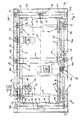
- a first frame 1 serves as a stand for the lifting table and has an essentially rectangular shape.
- the longitudinal beams 2 and 4 have a square cross-sectional profile (FIG. 3), while the cross beams 3 and 5 have a rectangular cross-sectional profile (FIG. 2).
- the height of the longitudinal and transverse beams is the same.
- the length of the longitudinal beams 2 and 4 corresponds approximately to twice the length of the transverse beams 3 and 5.
- a shaft 7 and 9 Adjacent to the crossbars 3 and 5 (FIGS. 1, 3) there is a shaft 7 and 9 at a distance a, respectively, which is held in its end sections in bearings 6 and 8 on the longitudinal beams 2 and 4.
- the two shafts 7 and 9 each have a lifting member on their end sections 7a, 7b and 9a, 9b, on which a lifting frame 18 rests under the effect of gravity.
- the lifting frame 18 is thus in four places, which ensures a high stability when lifting and lowering.
- a lifting cheek 11 which carries a crank pin 20 (FIG. 3), is rotatably arranged on one longitudinal side of the frame 1 on an end section 7a of the shaft 7 which projects laterally outward beyond the longitudinal beam 2.
- the axis 20a of the crank pin 20 lies at a distance e from the axis of rotation 17 of the shaft 7 (FIG. 4).
- the other end 7b of the shaft 7 carries a pulley 13 on its end section 7b, which projects laterally outwards beyond the other longitudinal beams 4 and in which a crank pin 20 is fastened axially.
- the axis 20a of the crank pin 20 lies at a distance e parallel to the axis of rotation 17 of the shaft 7 (FIG. 3).
- the belt 15 lies - in plan view according to FIG. 1 - approximately parallel to the longitudinal beam 4 outside the stand frame 1.
- an outer belt pulley 10b is arranged on the same drive shaft of the drive 10, on which lies a belt 16 which has a on the end 9b of the shaft 9 arranged pulley 14 loops.
- the belt 16 is also - in plan view according to FIG. 1 - approximately parallel to the longitudinal beam 4 outside the upright frame 1, but at a greater distance from the longitudinal beam than the belt 15.
- the belt drive 12 lying outside the stand frame 1 with the endless belts 15 and 16 is provided in such a way that all lifting members each have the same relative height to the stand 1.
- the stand frame 1 lies within the lifting frame; 1, the lifting frame 18 is thus larger than the stand frame 1.
- the lifting frame 18 is guided on the stand 1 so that it can move in height by means of guides 19.
- the guide 19 consists of a vertical U-profile 21, which is attached to the crossbar 3 or 5 of the stand frame 1 by an angle or the like.
- the opening of the U-profile 21 faces the crossbeam 23 or 25 of the lifting frame 18.
- a guide cam 26, which engages in the U-profile (FIG. 2), is fastened below the hollow profile of the crossbeams 23 and 25, which is rectangular in cross section.
- the lifting frame 18 is kept largely free of play in the longitudinal direction of the central longitudinal axis 27 of the lifting table and in the transverse direction. Tilting about the longitudinal central axis is prevented by the support of the longitudinal beams 22 and 24 of the lifting frame 18 on the crank pin 20.
- the belt drive 12 lies exactly between the stand frame 1 and the lifting frame 18 or between the longitudinal bar 4 of the stand frame 1 and the longitudinal bar 24 of the lifting frame 18.
- the longitudinal beams 22 and 24 of the lifting frame 18 are formed from a box section 30 (FIGS. 3, 4), which is open via a longitudinal side 31; such a profile is also described as a C-profile.
- the box section 30 of the longitudinal beams 22 and 24 is fixed at its ends to the cross beams 23 and 25.
- the open long sides 31 of the box section 30 face each other, that is, on the inside of the lifting frame 18.
- transport rollers 40 and 41 are arranged within the lifting frame 18 transversely to the longitudinal center axis 27 of the lifting table.
- the transport rollers are held at their ends 42 in bearings 43 which are inside the box section 30 are fixed on the closed longitudinal side 32 of the profile (FIG. 4).
- the end sections 44 of the transport rollers 40 and 41 lying within the box section 30 each carry a pulley 45 to 45d.
- the belt pulley 45 is driven by a belt pulley 29 via a belt 46, preferably a toothed belt, which is fixed in a rotationally fixed manner on the shaft of a drive motor 28.
- the drive motor 28 is attached to the lifting frame 18 and is adjusted with it.
- the pulley 45a arranged on the other end section of the transport roller 40 carries a belt 46a which wraps around the pulley 45b of the adjacent transport roller 41.
- the pulley 45c arranged on the end section 44 on the other side of the middle transport roller 41 drives a belt 46b which drives the transport roller 40 adjacent to the other crossbar 25 via the pulley 45d.
- This type of drive of the transport rollers 40 and 41 via the drive motor 28 is referred to in technical circles as a Z drive.
- Timing belts are preferably used as belts. The drive of the transport rollers via belts ensures quiet operation.
- the transport rollers 40 and 41 are coated in their end regions via a ring section 50 with a friction-increasing plastic or rubber.
- the arrangement of a rubber sleeve formed from a corresponding material as a ring section 50 is also advantageous.
- the ring sections 50 stand as drive rollers for the transport device or the skid beyond a cover of the lifting frame, as in FIG. 2 is shown.
- the cover essentially consists of two cover plates 47, which rest and are fastened on support flanges 48 on the longitudinal beams 22 and 24 of the lifting frame.
- the support flanges 48 are firmly connected to the box section 30 on the inside of the box section above the opening in the longitudinal side 31, for example welded.
- the bearing surface 48a (FIG. 4) of a support flange 48 lies somewhat below the horizontal surface 49 of the box section 30.
- the outer jacket of the ring section 50 lies somewhat above this surface 49.
- angle plates 39 are welded to the crossbars (Fig. 2).
- the horizontal leg of the angle plates lies below the plane determined by the cover plates 47.
- the box section 30 is provided over a part of its length in the pivoting range of the crank pin 20 with a reinforcing angle section 35, which has a running surface 36 made of a suitable material for a roller 37 rotatably arranged on the crank pin 20 having.
- the tread 36 fastened to the angle profile 35 and the roller 37 are formed from a noise-absorbing material such as rubber, in order to ensure low noise when the parts move relative to one another.
- the roller 37 rotatably mounted on the crank pin 20 is axially secured by means of a nut 38.
- the shafts 7 and 9 are driven via the belts 15 and 16, so that the crank pins 20 which are arranged eccentrically to the shaft axes pivot the axis of rotation 17 of the shafts and perform a lifting movement.
- the rollers 37 roll on the raceways 36 of the reinforcing angle profiles 35 on the box profile 30.
- the maximum stroke of the lifting table is reached when the crank pins lie vertically above the axes of rotation 17 of the shafts 7 and 9.
- the stroke achieved corresponds to twice the eccentricity e that the crank pins 20 have about the axis of rotation 17 of the shafts 7 and 9.
- the lifting frame 18 is moved into its uppermost lifting position and blocked in this position. Thereafter, the drive 10 is set in motion again so that the crank pins lift off the lifting frame and a vertical gap is formed between the crank pins and the lifting frame, which corresponds approximately to twice the eccentricity e. Because of this gap, the belt 16 can now be lifted off the pulley 14 and removed axially without further dismantling work. The belt 15 can also be removed in the same way. After the axial placement and tensioning of new belts, the crank pins are moved back into contact with the lifting frame and the blocking of the lifting frame is removed. The lift table is ready for use again.
- the belts 46 to 46b of the sterndrive of the transport rollers 40 and 41 can also be replaced in a simple manner without great disassembly.
- the lift table is moved to its uppermost position so that the open long sides are exposed to the inside. Now the bearings of the transport rollers driven by the belt to be replaced are released and the transport rollers are inclined so that the belt can be axially removed from the pulley. Through the open Long side 31 makes it easy to remove and replace the belt without any further assembly or disassembly work.
- stiffening plates 34 can be inserted and screwed into the open long side 31 of the box section, which are supported against the two long edges in the open long side 31.
- a plurality of stiffening plates 34 can be arranged over the length of a longitudinal bar 22 or 24.
- limit switches 60 are shown in the upper left, which are actuated by cams 61 rotating with the shaft 9.
- the limit switches are used in the electrical control of the lifting table. It may be advantageous to provide the limit switches 60 and the cams 61 which actuate them - sitting on an extension of the shaft 9 - lying outside the lifting frame, as a result of which there is easier access for maintenance work.
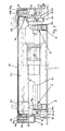
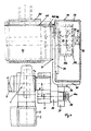
- 5 to 8 corresponds in its basic structure to the lifting table according to FIGS. 1 to 4; the same reference numbers have therefore been used for the same parts.
- the belt drive 12 with the belts 15 and 16 in turn lies outside the stand frame 1 on the outside next to the longitudinal beam 4.
- the lifting frame 18 is - seen in plan view according to FIG. 1 - with its one longitudinal beam 22 on the outside next to the belt drive 12 facing longitudinal bar 2 of the stand frame, while the other longitudinal bar 24 of the lifting frame 18 - in plan view - inside next to the longitudinal bar 4th of the stand frame 1.
- the longitudinal beam 24 of the lifting frame crosses the cross beams 3 and 5 of the stand frame.
- the belt drive 12 is thus also outside the lifting frame 18.
- the belt drive 12 is therefore freely accessible in every position of the lifting frame 18 from outside the frames 1 and 18, so that the endless belts 15 and 16 axially from the pulleys 10a; 14 and 10; 13 can be removed without having to be separated.
- a housing 33 (FIGS. 1, 2).
- each lifting member is further formed by a cam disk 111, the jacket of which forms a guide track 112, on which the lifting frame 18 rests under the action of gravity.
- a stub shaft 120 is advantageously attached to the lifting frame 18 and carries a roller 37 rolling on the guide track 112 (FIG. 8), which is secured axially by the nut 38.
- the roller 37 has at least one tread made of noise-absorbing material such as rubber; the roller 37 itself is advantageously made of such a material.
- the shaft ends 120 protrude into the lifting frame 18; a stub shaft 120 of the one longitudinal beam 22 lies opposite the stub shaft 120 of the other longitudinal beam 24, such that two stub shafts each lie on a common axis.
- the cam disks 111 which are arranged on the end sections 7a, 7b and 9a, 9b of the shafts 7 and 9 in a rotationally fixed manner, are in a plan view of FIG Lift table - within the lifting frame 18.
- cam disks 111 which are fixed on the end sections 7a and 9a lie outside the stand frame 1 laterally next to the longitudinal beams 2, while the cam disks 111 which are fixed on the other end sections 7b and 9b lie - inranges - within the stand frame 1 lie on the side of the bearing 8 facing the bearing 6.
- the guide 19 between the lifting frame 18 and the stand frame 1 in turn consists of a U-profile 21 which is attached to the crossbar 23 or 25 on the crossbar 3 or 5 of the stand frame 1.
- the web of a T-profile 21a engages in the vertical guideway of the U-profile 21, which is fixed vertically on the crossbeam 23 or 25 of the lifting frame 18.
- the stand frame 1 In addition to the position of the lifting frame 18 and stand frame 1 shown in FIG. 1, it may be advantageous to arrange the stand frame 1 lying within the lifting frame 18.
- the shaft ends carrying the pulleys 13 and 14 must then protrude under the longitudinal beam 24 of the lifting frame so that the belt drive 12 lies outside the lifting frame.
Abstract
Description
Die Erfindung betrifft einen Hubtisch zur Überwindung eines Höhensprungs in Förderstraßen für Transporteinrichtungen wie Skids oder dergleichen nach dem Oberbegriff des Anspruches 1.The invention relates to a lifting table for overcoming a jump in height in conveyor lines for transport devices such as skids or the like according to the preamble of
Bei einem bekannten Hubtisch dieser Art sind die Hubzapfen exzentrisch an Wellen gelagert, durch deren Drehung die Hubzapfen infolge ihrer exzentrischen Lagerung einen vertikalen Hub ausführen. Zur Drehung der Wellen ist ein Antrieb vorgesehen, der über Rollenketten mit auf den Wellen festgeflanschten Zahnrädern antriebsverbunden ist. Diese Rollenketten liegen innerhalb eines als Ständer ausgebildeten Rahmens.In a known lifting table of this type, the crank pins are mounted eccentrically on shafts, the rotation of which causes the crank pins to perform a vertical stroke due to their eccentric mounting. For the rotation of the shafts, a drive is provided which is connected to the drive via roller chains with gearwheels flanged onto the shafts. These roller chains lie within a frame designed as a stand.
Müssen die Ketten aufgrund Verschleißes ausgetauscht werden, so ist dies prinzipiell durch Öffnen eines Kettengliedes möglich. Verstärkt werden jedoch endlose Rollenketten eingesetzt, da diese nicht das Schwachglied eines Kettenschlosses aufweisen. Die endlosen Rollenketten müssen dann jedoch nach der Montage zur Endloskette verbunden werden, zum Beispiel durch Nieten oder dergleichen, was jedoch zeit- und arbeitsaufwendig ist. Soll eine bereits verbundene Endloskette montiert werden, muß zum Auflegen der Kette auf das Zahnrad die Welle auf zumindest einer Seite aus ihrem Lager gelöst werden, was zeit- und arbeitsaufwendig ist.If the chains have to be replaced due to wear, this is basically possible by opening a chain link. Endless roller chains are increasingly used, however, because they do not have the weak link of a chain lock. However, the endless roller chains must then be connected to form an endless chain after assembly, for example by rivets or the like, but this is time-consuming and labor-intensive is. If an already connected endless chain is to be installed, the shaft must be released from its bearing on at least one side to place the chain on the gear, which is time-consuming and labor-intensive.
Da der bekannte Hubtisch in Produktionsstraßen eingesetzt ist und jeder zusätzliche Montage- und Demontageaufwand die Ausfallzeit der Produktionsstraße erhöht, ist für den Betreiber einer Produktionsstraße ein geringer Zeitaufwand bei Reparatur- und Montagearbeiten von erheblicher Bedeutung.Since the known lifting table is used in production lines and each additional assembly and disassembly effort increases the downtime of the production line, a small amount of time for repair and assembly work is of considerable importance for the operator of a production line.
Der Erfindung liegt die Aufgabe zugrunde, einen Hubtisch nach dem Oberbegriff des Anspruches 1 derart weiterzubilden, daß der bei Wartungs- oder Reparaturarbeiten erforderliche Montage- und Demontageaufwand endloser Kraftübertragungsmittel möglichst gering ist.The invention has for its object to develop a lifting table according to the preamble of
Die Aufgabe wird erfindungsgemäß durch die kennzeichnenden Merkmale des Anspruches 1 gelöst.The object is achieved by the characterizing features of
Die Anordnung der Kraftübertragungselemente - in Draufsicht auf den Hubtisch gesehen - außerhalb des Ständerrahmens ermöglicht ein einfaches Freilegen des Hubantriebs, ohne daß umfangreiche Montage- oder Demontagearbeiten notwendig sind. Dabei ist von Vorteil, daß der Hubrahmen unter der Wirkung der Schwerkraft auf den Hubgliedern lediglich aufliegt, so daß er bei Bedarf von den Hubgliedern einfach abgehoben werden kann.The arrangement of the power transmission elements - seen in plan view of the lifting table - outside the stand frame enables the lifting drive to be easily exposed without extensive assembly or disassembly work being necessary. It is advantageous that the lifting frame only rests on the lifting members under the effect of gravity, so that it can be easily lifted off the lifting members if necessary.
In einem ersten Ausführungsbeispiel der Erfindung liegen die Kraftübertragungselemente - in Draufsicht auf den Hubtisch gesehen - zwischen dem Ständerrahmen und dem Hubrahmen.In a first exemplary embodiment of the invention, the force transmission elements — seen in plan view of the lifting table — lie between the stand frame and the lifting frame.
Hierdurch wird eine geringe Baubreite und Bauhöhe erzielt. Zum Wechseln der endlosen Kraftübertragungselemente wird der Hubtisch in seine oberste Hubposition gefahren, in dieser Lage festgekeilt und der Hubantrieb wieder in die unterste Lage verfahren. Da die Hubgleider am Hubrahmen nur anliegen, heben sie bei höhenfest verkeiltem Hubrahmen von diesem ab, wodurch ein dem Hub entsprechender Spalt zwischen jedem Hubglied und dem Hubrahmen entsteht. Die endlosen Kraftübertragungselemente zwischen dem Antrieb und der Hubanordnung können somit axial entnommen werden, ohne die Kraftübertragungselemente selbst zu öffnen. Die Montage- und Demontagearbeiten zum Auswechseln der endlosen Kraftübertragungselemente beschränken sich somit auf wenige Handgriffe, wie das Spannen und Entspannen nach der Montage bzw. zur Demontage.This results in a small overall width and overall height. To change the endless power transmission elements, the lifting table is moved to its uppermost lifting position, wedged in this position and the lifting drive is moved back to the lowest position. Since the lifting sliders only lie against the lifting frame, they lift off the lifting frame when the lifting frame is wedged in a fixed manner, which creates a gap corresponding to the stroke between each lifting element and the lifting frame. The endless power transmission elements between the drive and the lifting arrangement can thus be removed axially without opening the power transmission elements themselves. The assembly and disassembly work for replacing the endless power transmission elements is therefore limited to a few simple steps, such as tensioning and relaxing after assembly or disassembly.
In einem anderen Ausführungsbeispiel der Erfindung liegen - in Draufsicht auf den Hubtisch gesehen - die Kraftübertragungselemente außerhalb des Hubrahmens. Bei dieser Ausführung ist zwar die Baubreite größer, zur Montage oder Demontage der endlosen Kraftübertragungselemente ist ein Verfahren und ein Festkeilen des Hubtisches jedoch nicht erforderlich.In another embodiment of the invention, the power transmission elements are located outside the lifting frame, as seen in a top view of the lifting table. In this embodiment, the overall width is larger, but a movement and wedging of the lifting table is not necessary for the assembly or disassembly of the endless power transmission elements.
In Weiterbildung der Erfindung sind aufgrund der erfindungsgemäßen Anordnung der Kraftübertragungselemente nunmehr in einfacher Weise Treibriemen, vorzugsweise Zahnriemen, verwendbar, wodurch das Betriebsgeräusch eines derartigen Hubtisches deutlich gesenkt werden kann. Mit dem erfindungsgemäßen Hubtisch konnten Geräuschwerte von deutlich weniger als 70 dbA erzielt werden.In a further development of the invention, due to the arrangement of the power transmission elements according to the invention, drive belts, preferably toothed belts, can now be used in a simple manner, as a result of which the operating noise of such a lifting table can be significantly reduced. With the lifting table according to the invention, noise values of significantly less than 70 dbA could be achieved.
Vorteilhaft liegt der Ständerrahmen - in Draufsicht auf den Hubtisch gesehen - innerhalb des Hubrahmens. Liegt der Riementrieb auch außerhalb des Hubrahmens, kann es zur Vermeidung von überhöhten Lagerbelastungen der Antriebswellen der Hubanordnung zweckmäßig sein, wenn der dem Riementrieb benachbarte Längsbalken des Hubrahmens die Querbalken des Ständerrahmens kreuzt.The stand frame - seen in plan view of the lifting table - advantageously lies within the lifting frame. If the belt drive is also outside the lifting frame, it may be appropriate to avoid excessive bearing loads on the drive shafts of the lifting arrangement if the longitudinal bar of the lifting frame adjacent to the belt drive crosses the crossbars of the stand frame.
In einfacher Weise sind die Hubglieder als jeweils axial in einer Hubwange gehaltener Hubzapfen vorgesehen, der zur Erzielung eines geringen Betriebsgeräusches vorzugsweise mit einer Laufrolle an einer Laufbahn des Hubrahmens anliegt. In einfacher Weise kann die den Hubzapfen tragende Hubwange auch durch die Riemenscheibe gebildet sein, auf der das Kraftübertragungselement aufliegt.In a simple manner, the lifting members are each provided as a lifting pin which is axially held in a lifting cheek and which, in order to achieve low operating noise, preferably bears against a track of the lifting frame with a roller. In a simple manner, the lifting cheek that carries the crank pin can also be formed by the pulley on which the force transmission element rests.
In vorteilhafter Weiterbildung der Erfindung weist der Hubrahmen Kastenprofile als Längsbalken auf, die auf ihren einander zugewandten Längsseiten über ihre ganze Länge offen sind, wobei die im Inneren des Kastenprofils gelagerten Transportrollen des Hubrahmens über endlose Riemen angetrieben werden, die innerhalb des Kastenprofils liegen. Vorzugsweise sind hierzu Flachriemen oder Zahnriemen verwendet. Aufgrund der offenen Längsseiten ist wiederum nur ein geringer Montage- und Demontageaufwand zum Auswechseln eines endlosen Riemens notwenig. Dabei ist vorteilhaft vorgesehen, die Antriebsverbindungen zwischen benachbarten Transportrollen an wechselnden Endabschnitten der Transportrollen nach Art eines Z-Antriebs vorzusehen.In an advantageous development of the invention, the lifting frame has box profiles as longitudinal beams which are open over their entire length on their mutually facing longitudinal sides, the transport rollers of the lifting frame mounted in the interior of the box profile being driven by endless belts which lie within the box profile. Flat belts or toothed belts are preferably used for this purpose. Due to the open long sides, only a small amount of assembly and disassembly is required to replace an endless belt. It is advantageously provided to provide the drive connections between adjacent transport rollers at changing end sections of the transport rollers in the manner of a sterndrive.
Weitere Merkmale der Erfindung ergeben sich aus den weiteren Ansprüchen, der Beschreibung und der Zeichnung, in der ein nachfolgend im einzelnen beschriebenes Ausführungsbeispiel der Erfindung dargestellt ist. Es zeigen:
- Fig. 1
- eine Draufsicht auf ein erstes Ausführungsbeispiel eines erfindungsgemäßen Hubtisches mit abgenommenen Abdeckplatten,
- Fig. 2
- einen Schnitt längs der Linie A-B gemäß Fig. 1 mit montierten Abdeckplatten,
- Fig. 3
- einen Schnitt längs der Linie C-D gemäß Fig. 1 mit montierten Abdeckplatten,
- Fig. 4
- in vergrößerter Darstellung einen Schnitt längs der Linie E-F gemäß Fig. 1,
- Fig. 5
- eine Draufsicht auf ein weiteres Ausführungsbeispiel eines erfindungsgemäßen Hubtisches mit abgebnommenen Abdeckplatten,
- Fig. 6
- eine Seitenansicht auf den Hubtisch nach Fig. 5,
- Fig. 7
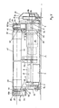
- einen Schnitt längs der Linie CC-DD in Fig. 5,
- Fig. 8
- in vergrößerter Darstellung eine Einzelheit aus der Schnittdarstellung gemäß Fig. 7.
- Fig. 1
- 2 shows a plan view of a first exemplary embodiment of a lifting table according to the invention with the cover plates removed,
- Fig. 2
- 2 shows a section along the line AB according to FIG. 1 with mounted cover plates,
- Fig. 3
- 2 shows a section along the line CD according to FIG. 1 with mounted cover plates,
- Fig. 4
- 2 shows an enlarged section along the line EF according to FIG. 1,
- Fig. 5
- 2 shows a plan view of a further exemplary embodiment of a lifting table according to the invention with the cover plates removed,
- Fig. 6
- 5 shows a side view of the lifting table according to FIG. 5,
- Fig. 7
- 4 shows a section along the line CC-DD in FIG. 5,
- Fig. 8
- an enlarged view of a detail from the sectional view of FIG. 7.
Aus der Draufsicht gemäß Fig. 1 bzw. Fig. 5 ist der Prinzipaufbau des erfindungsgemäßen Hubtisches erkennbar. Ein erster Rahmen 1 dient als Ständer des Hubtisches und hat im wesentlichen rechteckige Form. Im ersten Ausführungsbeispiel gemäß den Fig. 1 bis 4 haben die Längsbalken 2 und 4 ein quadratisches Querschnittsprofil (Fig. 3), während die Querbalken 3 und 5 ein rechteckiges Querschnittsprofil haben (Fig. 2). Die Höhe der Längs- und Querbalken ist gleich;. die Länge der Längsbalken 2 und 4 entspricht dabei etwa der doppelten Länge der Querbalken 3 und 5.The basic structure of the lifting table according to the invention can be seen from the top view according to FIG. 1 or FIG. 5. A
Benachbart zu den Querbalken 3 und 5 (Fig. 1, 3) liegt mit Abstand a jeweils eine Welle 7 bzw. 9, die in ihren Endabschnitten in Lagern 6 und 8 auf den Längsbalken 2 und 4 gehalten ist. Die beiden Wellen 7 und 9 tragen an ihren Endabschnitten 7a, 7b bzw. 9a, 9b drehfest jeweils ein Hubglied, auf denen ein Hubrahmen 18 unter Wirkung der Schwerkraft aufliegt. Der Hubrahmen 18 liegt somit an vier Stellen auf, wodurch eine hohe Stabilität beim Heben und Senken gewährleistet ist.Adjacent to the
Im ersten Ausführungsbeispiel nach den Fig. 1 bis 4 ist auf der einen Längsseite des Rahmens 1 auf einem seitlich nach außen über den Längsbalken 2 herausstehenden Endabschnitt 7a der Welle 7 eine Hubwange 11 drehfest angeordnet, die einen Hubzapfen 20 trägt (Fig. 3). Die Achse 20a des Hubzapfens 20 liegt mit einem Abstand e zur Drehachse 17 der Welle 7 (Fig. 4).In the first embodiment according to FIGS. 1 to 4, a lifting
Das andere Ende 7b der Welle 7 trägt auf seinem über den anderen Längsbalken 4 seitlich nach außen überstehenden Endabschnitt 7b eine Riemenscheibe 13, in der axial ein Hubzapfen 20 befestigt ist. Die Achse 20a des Hubzapfens 20 liegt in einem Abstand e parallel zur Drehachse 17 der Welle 7 (Fig. 3).The
Die auf beiden Endabschnitten 7a und 7b der Welle 7 angeordneten Hubglieder, die aus einer Hubwange 11 bzw. einer Riemenscheibe 13 mit einem Hubzapfen 20 bestehen, liegen mit den Achsen 20a der Zapfen 20 achsgleich zueinander; die Hubzapfen 20 haben bei jeder Drehstellung der Welle 7 relativ zum Ständer 1 die gleiche Höhenlage.The lifting members arranged on both
Die Lagerung der Welle 9 und die Anordnung von Hubzapfen 20 an deren Endabschnitten 9a und 9b entspricht identisch der bei der Welle 7.The mounting of the
Auf die Riemenscheibe 13 ist ein Riemen 15, vorzugsweise ein Zahnriemen aufgezogen, der eine von einem ständerfesten Antrieb 10 angetriebene Riemenscheibe 10a umschlingt. Der Riemen 15 liegt dabei - in Draufsicht gemäß Fig. 1 - etwa parallel zum Längsbalken 4 außerhalb des Ständerrahmens 1. Neben der Riemenscheibe 10a ist auf der gleichen Antriebswelle des Antriebs 10 eine äußere Riemenscheibe 10b angeordnet, auf der ein Riemen 16 aufliegt, welcher eine auf dem Ende 9b der Welle 9 angeordnete Riemenscheibe 14 umschlingt. Auch der Riemen 16 liegt - in Draufsicht gemäß Fig. 1 - etwa parallel zum Längsbalken 4 außerhalb des Ständerrahmens 1, jedoch mit größerem Abstand zum Längsbalken als der Riemen 15.A
Der außerhalb des Ständerrahmens 1 liegende Riementrieb 12 mit den Endlosriemen 15 und 16 ist so vorgesehen, daß alle Hubglieder jeweils eine gleiche relative Höhenlage zum Ständer 1 einnehmen.The
Im ersten Ausführungsbeispiel nach den Fig. 1 bis 4 liegt der Ständerrahmen 1 innerhalb des Hubrahmens; der Hubrahmen 18 ist in Draufsicht gemäß Fig. 1 also größer als der Ständerrahmen 1 ausgebildet.In the first exemplary embodiment according to FIGS. 1 to 4, the
Der Hubrahmen 18 ist mittels Führungen 19 höhenbeweglich am Ständer 1 geführt. Die Führung 19 besteht aus einem vertikalen U-Profil 21, welches am Querbalken 3 bzw. 5 des Ständerrahmens 1 durch einen Winkel oder dergleichen befestigt ist. Das U-Profil 21 liegt mit seiner Öffnung dem Querbalken 23 bzw. 25 des Hubrahmens 18 zugewandt. Unterhalb des im Querschnitt rechteckförmigen Hohlprofils der Querbalken 23 und 25 ist ein Führungsnocken 26 befestigt, der in das U-Profil eingreift (Fig. 2). Auf diese Weise ist der Hubrahmen 18 in Längsrichtung der Mittellängsachse 27 des Hubtisches und in Querrichtung dazu weitgehend spielfrei gehalten. Ein Kippen um die Längsmittelachse ist durch die Auflage der Längsbalken 22 und 24 des Hubrahmens 18 auf den Hubzapfen 20 verhindert. Der Riementrieb 12 liegt dabei genau zwischen dem Ständerrahmen 1 und dem Hubrahmen 18 bzw. zwischen dem Längsbalken 4 des Ständerrahmens 1 und dem Längsbalken 24 des Hubrahmens 18.The lifting
Die Längsbalken 22 und 24 des Hubrahmens 18 sind aus einem Kastenprofil 30 (Fig. 3, 4) gebildet, welches über eine Längsseite 31 offen ist; ein derartiges Profil wird auch als C-Profil beschrieben. Das Kastenprofil 30 der Längsbalken 22 und 24 ist an seinen Enden auf den Querbalken 23 und 25 festgelegt. Die offenen Längsseiten 31 des Kastenprofils 30 liegen dabei einander zugewandt, also auf der Innenseite des Hubrahmens 18.The
Innerhalb des Hubrahmens 18 sind quer zur Längsmittelachse 27 des Hubtisches liegende angetriebene Transportrollen 40 und 41 angeordnet. Die Transportrollen sind an ihren Enden 42 in Lagern 43 gehalten, die im Inneren des Kastenprofils 30 auf der geschlossenen Profillängsseite 32 festliegen (Fig. 4). Die innerhalb des Kastenprofils 30 liegenden Endabschnitte 44 der Transportrollen 40 und 41 tragen je eine Riemenscheibe 45 bis 45d. Wie aus Fig. 1 zu ersehen, ist die Riemenscheibe 45 über einen Riemen 46, vorzugsweise einen Zahnriemen, von einer Riemenscheibe 29 angetrieben, die auf der Welle eines Antriebsmotors 28 drehfest festliegt. Der Antriebsmotor 28 ist am Hubrahmen 18 befestigt und wird mit diesem verstellt.
Die auf dem anderen Endabschnitt der Transportrolle 40 angeordnete Riemenscheibe 45a trägt einen Riemen 46a, der die Riemenscheibe 45b der benachbarten Transportrolle 41 umschlingt. Somit wird die mittig angeordnete Transportrolle 41 vom Antrieb 28 über die Transportrolle 40 und den Riemen 46a angetrieben. Die auf dem Endabschnitt 44 der anderen Seite der mittleren Transportrolle 41 angeordnete Riemenscheibe 45c treibt einen Riemen 46b, der über die Riemenscheibe 45d die dem anderen Querbalken 25 benachbarte Transportrolle 40 antreibt. Diese Art des Antriebs der Transportrollen 40 und 41 über den Antriebsmotor 28 wird in Fachkreisen als Z-Antrieb bezeichnet. Als Riemen werden vorzugsweise Zahnriemen verwendet. Der Antrieb der Transportrollen über Riemen gewährleistet einen geräuscharmen Betrieb.The
Die Transportrollen 40 und 41 sind in ihren Endbereichen über einen Ringabschnitt 50 mit einem reiberhöhenden Kunststoff oder Gummi beschichtet. Auch ist die Anordnung einer aus entsprechendem Material gebildeten Gummimanschette als Ringabschnitt 50 vorteilhaft. Die Ringabschnitte 50 stehen als Treibrollen für die Transporteinrichtung bzw. den Skid über eine Abdeckung des Hubrahmens hinaus, wie in Fig. 2 dargestellt ist. Die Abdeckung besteht dabei im wesentlichen aus zwei Abdeckblechen 47, die auf Tragflanschen 48 an den Längsbalken 22 und 24 des Hubrahmens aufliegen und befestigt sind. Die Tragflansche 48 sind auf der Innenseite des Kastenprofils oberhalb der Öffnung in der Längsseite 31 mit dem Kastenprofil 30 fest verbunden, zum Beispiel verschweißt. Die Auflagefläche 48a (Fig. 4) eines Tragflansches 48 liegt dabei etwas unterhalb der horizontalen Oberfläche 49 des Kastenprofils 30. Der Außenmantel des Ringabschnittes 50 liegt etwas oberhalb dieser Oberfläche 49.The
Zum stirnseitigen Abschluß des Hubrahmens sind an den Querbalken 23 bzw. 25 Winkelbleche 39 angeschweißt (Fig. 2). Der horizontale Schenkel der Winkelbleche liegt dabei unterhalb der durch die Abdeckbleche 47 bestimmten Ebene.For the front end of the lifting
Wie insbesondere aus den Fig. 2 bis 4 ersichtlich, ist das Kastenprofil 30 über einen Teil seiner Länge im Schwenkbereich der Hubzapfen 20 mit einem verstärkenden Winkelprofil 35 versehen, welches eine Lauffläche 36 aus einem geeigneten Material für ein auf dem Hubzapfen 20 drehbar angeordnete Laufrolle 37 aufweist. Die am Winkelprofil 35 befestigte Lauffläche 36 sowie das Laufrolle 37 sind aus einem geräuschdämmenden Material wie zum Beispiel Gummi gebildet, um eine geringe Geräuschentwicklung bei Relativbewegung der Teile zueinander zu gewährleisten. Die auf dem Hubzapfen 20 drehbar gelagerte Laufrolle 37 ist mittels einer Mutter 38 axial gesichert.As can be seen in particular from FIGS. 2 to 4, the
Wird der Antrieb 10 in Betrieb gesetzt, werden über die Riemen 15 und 16 die Wellen 7 und 9 angetrieben, so daß die exzentrisch zu den Wellenachsen angeordneten Hubzapfen 20 um die Drehachse 17 der Wellen verschwenken und eine Hubbewegung ausführen. Dabei rollen die Laufrollen 37 auf den Laufbahnen 36 der verstärkenden Winkelprofile 35 am Kastenprofil 30 ab. Der maximale Hub des Hubtisches ist erreicht, wenn die Hubzapfen vertikal über den Drehachsen 17 der Wellen 7 und 9 liegen. Der erreichte Hub entspricht dabei der doppelten Exzentrizität e, die die Hubzapfen 20 zur Drehachse 17 der Wellen 7 und 9 aufweisen.If the
Muß einer der Riemen 15 oder 16 oder beide Riemen des Riementriebs 12 ausgetauscht werden, wird der Hubrahmen 18 in seine oberste Hublage verfahren und in dieser Lage blockiert. Danach wird der Antrieb 10 wieder in Bewegung gesetzt, so daß die Hubzapfen vom Hubrahmen abheben und ein vertikaler Spalt zwischen den Hubzapfen und dem Hubrahmen entsteht, der etwa der doppelten Exzentrizität e entspricht. Aufgrund dieses Spaltes kann nun ohne weitere Demontagearbeiten der Riemen 16 von der Riemenscheibe 14 abgehoben und axial abgenommen werden. In der gleichen Weise ist auch der Riemen 15 zu entnehmen. Nach dem axialen Auflegen und Spannen neuer Riemen werden die Hubzapfen wieder in Anlage an den Hubrahmen gefahren und die Blockierung des Hubrahmens entfernt. Der Hubtisch ist wieder betriebsbereit.If one of the
Auch ein Auswechseln der Riemen 46 bis 46b des Z-Antriebs der Transportrollen 40 und 41 ist auf einfache Weise ohne großen Demontageaufwand möglich. Der Hubtisch wird in seine oberste Lage gefahren, so daß die offenen Längsseiten nach innen freiliegen. Nun werden die Lager der von dem auszutauschenden Riemen angetriebenen Transportrollen gelöst und die Transportrollen schräggestellt, so daß der Riemen axial von der Riemenscheibe entfernt werden kann. Durch die offene Längsseite 31 ist ein leichtes Entnehmen und Austauschen des Riemens ohne weitere Montage- oder Demontagearbeiten möglich.The
Im Bedarfsfall können in der offenen Längsseite 31 des Kastenprofils 30 Versteifungsplatten 34 eingesetzt und festgeschraubt werden, die sich gegen die beiden Längskanten in der offenen Längsseite 31 abstützen. So können - wie zum Beispiel Fig. 2 zeigt - über die Länge eines Längsbalkens 22 bzw. 24 mehrere Versteifungsplatten 34 angeordnet werden.If necessary, 30
In Fig. 1 sind oben links Endschalter 60 gezeigt, die von mit der Welle 9 drehenden Nocken 61 betätigt sind. Die Endschalter sind in der elektrischen Steuerung des Hubtisches verwendet. Es kann vorteilhaft sein, die Endschalter 60 und die sie betätigenden Nocken 61 - auf einer Verlängerung der Welle 9 sitzend - außerhalb des Hubrahmens liegend vorzusehen, wodurch eine einfachere Zugänglichkeit für Wartungsarbeiten gegeben ist.1,
Das Ausführungsbeispiel eines erfindungsgemäßen Hubtisches gemäß den Fig. 5 bis 8 entspricht im Grundaufbau dem Hubtisch gemäß den Fig. 1 bis 4; für gleiche Teile wurden daher gleiche Bezugsziffern verwendet.5 to 8 corresponds in its basic structure to the lifting table according to FIGS. 1 to 4; the same reference numbers have therefore been used for the same parts.
Wie Fig. 5 zeigt, liegt der Riementrieb 12 mit den Riemen 15 und 16 wiederum außerhalb des Ständerrahmens 1 außen neben dem Längsbalken 4. Der Hubrahmen 18 liegt - in Draufsicht gemäß Fig. 1 gesehen - mit seinem einen Längsbalken 22 außen neben dem dem Riementrieb 12 abgewandten Längsbalken 2 des Ständerrahmens, während der andere Längsbalken 24 des Hubrahmens 18 - in Draufsicht - innen neben dem Längsbalken 4 des Ständerrahmens 1 liegt. Dabei kreuzt der Längsbalken 24 des Hubrahmens die Querbalken 3 und 5 des Ständerrahmens. In Draufsicht auf den Hubtisch gesehen liegt der Riementrieb 12 somit auch außerhalb des Hubrahmens 18. Der Riementrieb 12 ist daher in jeder Lage des Hubrahmens 18 von außerhalb der Rahmen 1 und 18 frei zugänglich, so daß die endlosen Riemen 15 und 16 axial von den Riemenscheiben 10a; 14 und 10; 13 abgenommen werden können, ohne aufgetrennt werden zu müssen.As shown in FIG. 5, the
Um eine Gefährdung durch den außen liegenden Riementrieb 12 auszuschließen, ist dieser durch ein Gehäuse 33 (Fig. 1, 2) abgedeckt.In order to rule out any danger from the
Im Ausführungsbeispiel nach den Fig. 5 bis 8 ist ferner jedes Hubglied durch eine Nockenscheibe 111 gebildet, deren Mantel eine Führungsbahn 112 bildet, auf der der Hubrahmen 18 unter Wirkung der Schwerkraft aufliegt. Vorteilhaft ist am Hubrahmen 18 ein Wellenstummel 120 befestigt, der eine auf der Führungsbahn 112 abrollende Laufrolle 37 trägt (Fig. 8), die axial durch die Mutter 38 gesichert ist. Die Laufrolle 37 hat zumindest eine Lauffläche aus geräuschdämmendem Material wie zum Beispiel Gummi; vorteilhaft ist die Laufrolle 37 selbst aus einem derartigen Material gefertigt.In the exemplary embodiment according to FIGS. 5 to 8, each lifting member is further formed by a
Wie aus der Draufsicht auf den Hubtisch gemäß Fig. 5 ersichtlich, ragen die Wellenstummel 120 in den Hubrahmen 18 hinein; ein Wellenstummel 120 des einen Längsbalkens 22 liegt dabei dem Wellenstummel 120 des anderen Längsbalkens 24 gegenüber, derart, daß je zwei Wellenstummel auf einer gemeinsamen Achse liegen. Entsprechend liegen die auf den Endabschnitten 7a, 7b bzw. 9a, 9b der Wellen 7 und 9 drehfest angeordneten Nockenscheiben 111 - in Draufsicht auf den Hubtisch - innerhalb des Hubrahmens 18. Dabei liegen die auf den Endabschnitten 7a bzw. 9a festliegenden Nockenscheiben 111 außerhalb des Ständerrahmens 1 seitlich neben den Längsbalken 2, während die auf den anderen Endabschnitten 7b zw. 9b festliegenden Nockenscheiben 111 - in Draufischt - innerhalb des Ständerrahmens 1 auf der dem Lager 6 zugewandten Seite des Lagers 8 liegen.5, the shaft ends 120 protrude into the lifting
Die Führung 19 zwischen dem Hubrahmen 18 und dem Ständerrahmen 1 besteht wiederum aus einem U-Profil 21, das dem Querbalken 23 bzw. 25 zugewandt am Querbalken 3 bzw. 5 des Ständerrahmens 1 befestigt ist. In die vertikale Führungsbahn des U-Profils 21 greift der Steg eines T-Profils 21a ein, das vertikal am Querbalken 23 bzw. 25 des Hubrahmens 18 festliegt.The
Neben der in Fig. 1 gezeichneten Lage von Hubrahmen 18 und Ständerrahmen 1 kann es vorteilhaft sein, den Ständerrahmen 1 innerhalb des Hubrahmens 18 liegend anzuordnen. Die die Riemenscheiben 13 und 14 tragenden Wellenenden müssen dann unter dem Längsbalken 24 des Hubrahmens durchragen, damit der Riementrieb 12 außerhalb des Hubrahmens liegt.In addition to the position of the lifting
Claims (13)
dadurch gekennzeichnet, daß der Hubrahmen (18) unter Wirkung der Schwerkraft auf den Hubgliedern aufliegt.Lift table according to claim 1,
characterized in that the lifting frame (18) rests on the lifting members under the action of gravity.
dadurch gekennzeichnet, daß - in Draufsicht auf den Hubtisch gesehen - die Kraftübertragungselemente (15, 16) zwischen dem Ständerrahmen (1) und dem Hubrahmen (18) liegen.Lift table according to claim 1 and 2,
characterized in that - seen in plan view of the lifting table - the force transmission elements (15, 16) lie between the stand frame (1) and the lifting frame (18).
dadurch gekennzeichnet, daß der Ständerrahmen (1) - in Draufsicht auf den Hubtisch gesehen - innerhalb des Hubrahmens (18) liegt.Lift table according to one of claims 1 to 3,
characterized in that the stand frame (1) - seen in plan view of the lifting table - lies within the lifting frame (18).
dadurch gekennzeichnet, daß die Kraftübertragungselemente (15, 16) Riemen, vorzugsweise Zahnriemen sind.Lift table according to one of claims 1 to 4,
characterized in that the force transmission elements (15, 16) are belts, preferably toothed belts.
dadurch gekennzeichnet, daß - in Draufsicht gesehen - ein dem Riementrieb (12) benachbarter Längsbalken (24) des Hubrahmens (18) die Querbalken (3, 5) des Ständerrahmens (1) kreuzt.Lift table according to claim 1 or 2,
characterized in that - seen in plan view - a longitudinal bar (24) of the lifting frame (18) adjacent to the belt drive (12) crosses the transverse bars (3, 5) of the stand frame (1).
dadurch gekennzeichnet, daß das Hubglied ein axial in einer Hubwange (11) gehaltener Zapfen (20) ist, der vorzugsweise mit einer insbesondere aus einem geräuschdämmenden Material bestehenden Laufrolle (37) an einer Laufbahn (35) des Hubrahmens (18) anliegt.Lift table according to one of claims 1 to 6,
characterized in that the lifting member is a pin (20) held axially in a lifting cheek (11), which preferably rests against a track (35) of the lifting frame (18) with a roller (37), in particular made of a sound-absorbing material.
dadurch gekennzeichnet, daß die den Hubzapfen (20) tragende Hubwange Teil einer Riemenscheibe (13, 14) ist, auf der ein Kraftübertragungselement (15, 16) aufliegt (Fig. 3).Lift table according to claim 7,
characterized in that the lifting cheek carrying the crank pin (20) is part of a pulley (13, 14) on which a force transmission element (15, 16) rests (Fig. 3).
dadurch gekennzeichnet, daß das Hubglied eine Nockenscheibe (111) ist, auf deren Führungsbahn (112) der Hubrahmen (18) vorzugsweise mit einer insbesondere aus einem geräuschdämmenden Material bestehenden Laufrolle (37) aufliegt.Lift table according to one of claims 1 to 6,
characterized in that the lifting member is a cam (111), on the guide track (112) of which Lift frame (18) preferably rests with a roller (37), which is composed in particular of a sound-absorbing material.
dadurch gekennzeichnet, daß parallel zu den Querbalken (3, 5) des Ständerrahmens (1) mindestens eine in Lagern (6, 8) an den Längsbalken (2, 4) des Ständerrahmens (1) gehaltene Welle (7, 9) angeordnet ist, die an ihren Endabschnitten (7a, 7b; 9a, 9b) je ein Hubglied trägt.Lift table according to one of claims 1 to 9,
characterized in that at least one shaft (7, 9) held in bearings (6, 8) on the longitudinal beams (2, 4) of the stand frame (1) is arranged parallel to the transverse beams (3, 5) of the stand frame (1), which carries a lifting member at its end sections (7a, 7b; 9a, 9b).
dadurch gekennzeichnet, daß die Längsbalken (22, 24) des Hubrahmens (18) aus auf ihren einander zugewandten Längsseiten (31) offenen Kastenprofilen (30) bestehen, wobei die im Inneren des Kastenprofils (30) gelagerten Transportrollen (40, 41) des Hubrahmens (18) über innerhalb des Kastenprofils (30) liegende Riemen (46, 46a, 46b) angetrieben sind.Lift table according to one of claims 1 to 10,
characterized in that the longitudinal beams (22, 24) of the lifting frame (18) consist of box sections (30) open on their mutually facing longitudinal sides (31), the transport rollers (40, 41) of the lifting frame mounted in the interior of the box section (30) (18) are driven by belts (46, 46a, 46b) lying within the box section (30).
dadurch gekennzeichnet, daß benachbarte Transportrollen (40, 41) an wechselnden Endabschnitten (44) der Transportrollen (40, 41) von endlosen Antriebsmitteln nach Art eines Z-Antriebs angetrieben sind.Lift table according to claim 11,
characterized in that adjacent transport rollers (40, 41) at changing end sections (44) of the transport rollers (40, 41) are driven by endless drive means in the manner of a sterndrive.
dadurch gekennzeichnet, daß die offene Längsseite (31) des Kastenprofils (30) durch zwischen den Längskanten der offenen Längsseite (31) angeordnete, lösbare Platten (34) versteift ist.Lift table according to claim 11 or 12,
characterized in that the open long side (31) of the box section (30) is stiffened by releasable plates (34) arranged between the long edges of the open long side (31).
Applications Claiming Priority (4)
| Application Number | Priority Date | Filing Date | Title |
|---|---|---|---|
| DE19904011318 DE4011318A1 (en) | 1990-04-07 | 1990-04-07 | Lifting table between transport sections |
| DE4011318 | 1990-04-07 | ||
| DE4109631 | 1991-03-23 | ||
| DE19914109631 DE4109631B4 (en) | 1990-04-07 | 1991-03-23 | Lift table for overcoming a jump in height in conveyor lines |
Publications (2)
| Publication Number | Publication Date |
|---|---|
| EP0451717A1 true EP0451717A1 (en) | 1991-10-16 |
| EP0451717B1 EP0451717B1 (en) | 1994-10-19 |
Family
ID=25891992
Family Applications (1)
| Application Number | Title | Priority Date | Filing Date |
|---|---|---|---|
| EP19910105391 Expired - Lifetime EP0451717B1 (en) | 1990-04-07 | 1991-04-05 | Elevating platform for surmounting a difference in level of conveyor tracks |
Country Status (3)
| Country | Link |
|---|---|
| EP (1) | EP0451717B1 (en) |
| DE (1) | DE4109631B4 (en) |
| ES (1) | ES2064795T3 (en) |
Cited By (7)
| Publication number | Priority date | Publication date | Assignee | Title |
|---|---|---|---|---|
| EP1428774A1 (en) * | 2002-12-09 | 2004-06-16 | Siemens Aktiengesellschaft | Elevating platform for a transport device in a conveyor track |
| AT500887A1 (en) * | 2002-10-19 | 2006-04-15 | Transnorm System Gmbh | Lift table |
| CN104495345A (en) * | 2014-12-25 | 2015-04-08 | 江苏冠宇机械设备制造有限公司 | Submit outlet moving machine |
| CN104528366A (en) * | 2014-12-27 | 2015-04-22 | 江苏冠宇机械设备制造有限公司 | Rotating device used for automobile production line |
| CN104528308A (en) * | 2014-12-26 | 2015-04-22 | 江苏冠宇机械设备制造有限公司 | Movement device used for automobile production line |
| CN107934866A (en) * | 2017-12-07 | 2018-04-20 | 江苏汤辰机械装备制造股份有限公司 | A kind of laminated floor slab flowing water line turnover device and method |
| US10315853B2 (en) | 2015-08-10 | 2019-06-11 | Superior Industries, Inc. | Conveyor leveling systems and methods |
Families Citing this family (2)
| Publication number | Priority date | Publication date | Assignee | Title |
|---|---|---|---|---|
| DE29700863U1 (en) * | 1997-01-20 | 1998-10-01 | Dennerlein Gmbh | Conveying device, in particular for discharging and / or separating goods |
| ES2273570B1 (en) * | 2005-04-15 | 2008-03-16 | Inveral, S.A. | HYDRAULIC ELEVATOR CART. |
Citations (2)
| Publication number | Priority date | Publication date | Assignee | Title |
|---|---|---|---|---|
| DE1127915B (en) * | 1959-08-26 | 1962-04-19 | George Merrill Martin | Sheet stacker |
| DE1903687U (en) * | 1964-07-29 | 1964-11-05 | Martini & Cie | PALLET LIFTING TABLE. |
Family Cites Families (6)
| Publication number | Priority date | Publication date | Assignee | Title |
|---|---|---|---|---|
| FR1583428A (en) * | 1968-03-01 | 1969-10-31 | Jesus Henri Leon Lucien | CHANGE OF DIRECTION CONVEYOR DEVICE |
| DE2108620A1 (en) * | 1971-02-24 | 1972-08-31 | Fritz Riedel Und Soehne | Multi-lane material transport line with semi-automatic cross transport device |
| DE3232764C2 (en) * | 1982-09-03 | 1985-03-07 | Mannesmann AG, 4000 Düsseldorf | Transfer station for conveyed goods |
| DE3445801A1 (en) * | 1984-12-15 | 1986-06-19 | Mato Maschinen- Und Metallwarenfabrik Curt Matthaei Gmbh & Co Kg, 6050 Offenbach | Inward and outward transfer station |
| DE3601699A1 (en) * | 1986-01-22 | 1987-07-23 | Bosch Gmbh Robert | CONVEYOR FOR TRANSPORTING WORKPIECES |
| DE8914111U1 (en) * | 1989-11-30 | 1990-01-18 | Wegoma Gmbh Maschinenfabrik, 7531 Eisingen, De |
-
1991
- 1991-03-23 DE DE19914109631 patent/DE4109631B4/en not_active Expired - Lifetime
- 1991-04-05 EP EP19910105391 patent/EP0451717B1/en not_active Expired - Lifetime
- 1991-04-05 ES ES91105391T patent/ES2064795T3/en not_active Expired - Lifetime
Patent Citations (2)
| Publication number | Priority date | Publication date | Assignee | Title |
|---|---|---|---|---|
| DE1127915B (en) * | 1959-08-26 | 1962-04-19 | George Merrill Martin | Sheet stacker |
| DE1903687U (en) * | 1964-07-29 | 1964-11-05 | Martini & Cie | PALLET LIFTING TABLE. |
Cited By (9)
| Publication number | Priority date | Publication date | Assignee | Title |
|---|---|---|---|---|
| AT500887A1 (en) * | 2002-10-19 | 2006-04-15 | Transnorm System Gmbh | Lift table |
| AT500887B1 (en) * | 2002-10-19 | 2007-02-15 | Transnorm System Gmbh | Lift table |
| EP1428774A1 (en) * | 2002-12-09 | 2004-06-16 | Siemens Aktiengesellschaft | Elevating platform for a transport device in a conveyor track |
| CN104495345A (en) * | 2014-12-25 | 2015-04-08 | 江苏冠宇机械设备制造有限公司 | Submit outlet moving machine |
| CN104495345B (en) * | 2014-12-25 | 2016-11-23 | 江苏冠宇机械设备制造有限公司 | Submit outlet line-shifting machine to |
| CN104528308A (en) * | 2014-12-26 | 2015-04-22 | 江苏冠宇机械设备制造有限公司 | Movement device used for automobile production line |
| CN104528366A (en) * | 2014-12-27 | 2015-04-22 | 江苏冠宇机械设备制造有限公司 | Rotating device used for automobile production line |
| US10315853B2 (en) | 2015-08-10 | 2019-06-11 | Superior Industries, Inc. | Conveyor leveling systems and methods |
| CN107934866A (en) * | 2017-12-07 | 2018-04-20 | 江苏汤辰机械装备制造股份有限公司 | A kind of laminated floor slab flowing water line turnover device and method |
Also Published As
| Publication number | Publication date |
|---|---|
| EP0451717B1 (en) | 1994-10-19 |
| ES2064795T3 (en) | 1995-02-01 |
| DE4109631B4 (en) | 2004-09-16 |
| DE4109631A1 (en) | 1992-09-24 |
Similar Documents
| Publication | Publication Date | Title |
|---|---|---|
| DE602004000785T2 (en) | Conveyor with carriers | |
| EP0857679A2 (en) | Device for winding a web of material | |
| EP2593384A1 (en) | Transfer conveying apparatus | |
| EP0291775A2 (en) | Apparatus for the simultaneous biaxial treatment of films | |
| DE3513381A1 (en) | Deflection/displacement module for workpieces, workpiece supports or the like | |
| DE1271369B (en) | Device for parking motor vehicles or the like. | |
| DE102012110764A1 (en) | Moving pavement for transporting people, has conveying and supporting elements interconnected with one another by endless element loop and comprising motor for moving loop, where supporting elements are arranged between conveying elements | |
| DE6903037U (en) | PARKING SCAFFOLDING WITH CIRCULAR PLATFORMS FOR VEHICLES. | |
| EP0434862B1 (en) | Lifting device, especially for conveyors | |
| EP0451717B1 (en) | Elevating platform for surmounting a difference in level of conveyor tracks | |
| DE2506560A1 (en) | DRIVEN CHAIN CONVEYOR | |
| EP0353556A1 (en) | Device for storing elongate articles | |
| EP0008082B1 (en) | Garage for parking vehicles one above the other | |
| DE2722320C2 (en) | Conveyor with overlapping plates | |
| DE2458645A1 (en) | PERSONAL TRANSPORT SYSTEM | |
| DE4011318C2 (en) | ||
| DE2018199C3 (en) | Device for the continuous production of rigid foam panels laminated with flexible foils, in particular based on polyurethane | |
| DE2012375A1 (en) | Apparatus for treating foodstuffs and a method for cleaning the apparatus | |
| EP0704404B1 (en) | Lifting platform | |
| DE10132350B4 (en) | lifting device | |
| EP0154290A2 (en) | Garage shaped as a wheel | |
| DE1434753C (en) | Device for the vertical and / or horizontal and / or inclined transport of vehicles, in particular in garages | |
| DE60100214T2 (en) | Swivel station for the conveyor device of a treatment plant | |
| EP3081448B1 (en) | Station for an aerial cableway with transport device and roof structure | |
| AT17658B (en) | Guide device on a rolling mill for the production of <IMAGE> carriers. |
Legal Events
| Date | Code | Title | Description |
|---|---|---|---|
| PUAI | Public reference made under article 153(3) epc to a published international application that has entered the european phase |
Free format text: ORIGINAL CODE: 0009012 |
|
| AK | Designated contracting states |
Kind code of ref document: A1 Designated state(s): BE ES FR GB IT LU NL SE |
|
| 17P | Request for examination filed |
Effective date: 19920331 |
|
| 17Q | First examination report despatched |
Effective date: 19930310 |
|
| RBV | Designated contracting states (corrected) |
Designated state(s): ES FR GB IT SE |
|
| GRAA | (expected) grant |
Free format text: ORIGINAL CODE: 0009210 |
|
| RAP1 | Party data changed (applicant data changed or rights of an application transferred) |
Owner name: STOTZ, KRAEMER GMBH MATERIALFLUSSYSTEME UND AUTOMA |
|
| AK | Designated contracting states |
Kind code of ref document: B1 Designated state(s): ES FR GB IT SE |
|
| ET | Fr: translation filed | ||
| ITF | It: translation for a ep patent filed |
Owner name: STUDIO JAUMANN |
|
| PG25 | Lapsed in a contracting state [announced via postgrant information from national office to epo] |
Ref country code: SE Effective date: 19950119 |
|
| REG | Reference to a national code |
Ref country code: ES Ref legal event code: FG2A Ref document number: 2064795 Country of ref document: ES Kind code of ref document: T3 |
|
| GBT | Gb: translation of ep patent filed (gb section 77(6)(a)/1977) |
Effective date: 19950124 |
|
| PLBE | No opposition filed within time limit |
Free format text: ORIGINAL CODE: 0009261 |
|
| STAA | Information on the status of an ep patent application or granted ep patent |
Free format text: STATUS: NO OPPOSITION FILED WITHIN TIME LIMIT |
|
| 26N | No opposition filed | ||
| REG | Reference to a national code |
Ref country code: GB Ref legal event code: IF02 |
|
| PGFP | Annual fee paid to national office [announced via postgrant information from national office to epo] |
Ref country code: ES Payment date: 20080429 Year of fee payment: 18 |
|
| PGFP | Annual fee paid to national office [announced via postgrant information from national office to epo] |
Ref country code: IT Payment date: 20080426 Year of fee payment: 18 |
|
| PGFP | Annual fee paid to national office [announced via postgrant information from national office to epo] |
Ref country code: FR Payment date: 20080412 Year of fee payment: 18 |
|
| PGFP | Annual fee paid to national office [announced via postgrant information from national office to epo] |
Ref country code: GB Payment date: 20080421 Year of fee payment: 18 |
|
| GBPC | Gb: european patent ceased through non-payment of renewal fee |
Effective date: 20090405 |
|
| REG | Reference to a national code |
Ref country code: FR Ref legal event code: ST Effective date: 20091231 |
|
| PG25 | Lapsed in a contracting state [announced via postgrant information from national office to epo] |
Ref country code: FR Free format text: LAPSE BECAUSE OF NON-PAYMENT OF DUE FEES Effective date: 20091222 Ref country code: GB Free format text: LAPSE BECAUSE OF NON-PAYMENT OF DUE FEES Effective date: 20090405 |
|
| REG | Reference to a national code |
Ref country code: ES Ref legal event code: FD2A Effective date: 20090406 |
|
| PG25 | Lapsed in a contracting state [announced via postgrant information from national office to epo] |
Ref country code: ES Free format text: LAPSE BECAUSE OF NON-PAYMENT OF DUE FEES Effective date: 20090406 |
|
| PG25 | Lapsed in a contracting state [announced via postgrant information from national office to epo] |
Ref country code: IT Free format text: LAPSE BECAUSE OF NON-PAYMENT OF DUE FEES Effective date: 20090405 |