EP0451463B1 - Multiple transducer selector - Google Patents
Multiple transducer selector Download PDFInfo
- Publication number
- EP0451463B1 EP0451463B1 EP91102165A EP91102165A EP0451463B1 EP 0451463 B1 EP0451463 B1 EP 0451463B1 EP 91102165 A EP91102165 A EP 91102165A EP 91102165 A EP91102165 A EP 91102165A EP 0451463 B1 EP0451463 B1 EP 0451463B1
- Authority
- EP
- European Patent Office
- Prior art keywords
- transducer
- imager
- attributes
- display
- transducers
- Prior art date
- Legal status (The legal status is an assumption and is not a legal conclusion. Google has not performed a legal analysis and makes no representation as to the accuracy of the status listed.)
- Expired - Lifetime
Links
- 238000005096 rolling process Methods 0.000 claims description 6
- 238000000034 method Methods 0.000 description 5
- 238000012285 ultrasound imaging Methods 0.000 description 5
- 230000002463 transducing effect Effects 0.000 description 4
- 238000010586 diagram Methods 0.000 description 3
- 238000003384 imaging method Methods 0.000 description 3
- 238000002604 ultrasonography Methods 0.000 description 3
- 238000003491 array Methods 0.000 description 2
- 230000006835 compression Effects 0.000 description 2
- 238000007906 compression Methods 0.000 description 2
- 238000002592 echocardiography Methods 0.000 description 2
- 230000035515 penetration Effects 0.000 description 2
- 230000002688 persistence Effects 0.000 description 2
- RPOKRGMOEWYIKB-ZFCLCKFASA-N (2r,3r,4r,5r)-n-[(4-ethenylphenyl)methyl]-2,3,6-trihydroxy-5-methyl-4-[(2r,3r,4s,5r,6r)-3,4,5-trihydroxy-6-(hydroxymethyl)oxan-2-yl]oxyhexanamide Chemical compound O([C@H]([C@@H](CO)C)[C@H](O)[C@@H](O)C(=O)NCC=1C=CC(C=C)=CC=1)[C@@H]1O[C@H](CO)[C@H](O)[C@H](O)[C@H]1O RPOKRGMOEWYIKB-ZFCLCKFASA-N 0.000 description 1
- 230000006978 adaptation Effects 0.000 description 1
- 238000003745 diagnosis Methods 0.000 description 1
- 238000012986 modification Methods 0.000 description 1
- 230000004048 modification Effects 0.000 description 1
- 230000002093 peripheral effect Effects 0.000 description 1
- 238000001356 surgical procedure Methods 0.000 description 1
- 230000002792 vascular Effects 0.000 description 1
Images


Classifications
-
- G—PHYSICS
- G10—MUSICAL INSTRUMENTS; ACOUSTICS
- G10K—SOUND-PRODUCING DEVICES; METHODS OR DEVICES FOR PROTECTING AGAINST, OR FOR DAMPING, NOISE OR OTHER ACOUSTIC WAVES IN GENERAL; ACOUSTICS NOT OTHERWISE PROVIDED FOR
- G10K11/00—Methods or devices for transmitting, conducting or directing sound in general; Methods or devices for protecting against, or for damping, noise or other acoustic waves in general
- G10K11/18—Methods or devices for transmitting, conducting or directing sound
- G10K11/26—Sound-focusing or directing, e.g. scanning
- G10K11/34—Sound-focusing or directing, e.g. scanning using electrical steering of transducer arrays, e.g. beam steering
- G10K11/341—Circuits therefor
-
- A—HUMAN NECESSITIES
- A61—MEDICAL OR VETERINARY SCIENCE; HYGIENE
- A61B—DIAGNOSIS; SURGERY; IDENTIFICATION
- A61B8/00—Diagnosis using ultrasonic, sonic or infrasonic waves
-
- G—PHYSICS
- G01—MEASURING; TESTING
- G01S—RADIO DIRECTION-FINDING; RADIO NAVIGATION; DETERMINING DISTANCE OR VELOCITY BY USE OF RADIO WAVES; LOCATING OR PRESENCE-DETECTING BY USE OF THE REFLECTION OR RERADIATION OF RADIO WAVES; ANALOGOUS ARRANGEMENTS USING OTHER WAVES
- G01S7/00—Details of systems according to groups G01S13/00, G01S15/00, G01S17/00
- G01S7/52—Details of systems according to groups G01S13/00, G01S15/00, G01S17/00 of systems according to group G01S15/00
- G01S7/52017—Details of systems according to groups G01S13/00, G01S15/00, G01S17/00 of systems according to group G01S15/00 particularly adapted to short-range imaging
- G01S7/52053—Display arrangements
- G01S7/52057—Cathode ray tube displays
-
- G—PHYSICS
- G01—MEASURING; TESTING
- G01S—RADIO DIRECTION-FINDING; RADIO NAVIGATION; DETERMINING DISTANCE OR VELOCITY BY USE OF RADIO WAVES; LOCATING OR PRESENCE-DETECTING BY USE OF THE REFLECTION OR RERADIATION OF RADIO WAVES; ANALOGOUS ARRANGEMENTS USING OTHER WAVES
- G01S7/00—Details of systems according to groups G01S13/00, G01S15/00, G01S17/00
- G01S7/52—Details of systems according to groups G01S13/00, G01S15/00, G01S17/00 of systems according to group G01S15/00
- G01S7/52017—Details of systems according to groups G01S13/00, G01S15/00, G01S17/00 of systems according to group G01S15/00 particularly adapted to short-range imaging
- G01S7/52079—Constructional features
-
- A—HUMAN NECESSITIES
- A61—MEDICAL OR VETERINARY SCIENCE; HYGIENE
- A61B—DIAGNOSIS; SURGERY; IDENTIFICATION
- A61B8/00—Diagnosis using ultrasonic, sonic or infrasonic waves
- A61B8/44—Constructional features of the ultrasonic, sonic or infrasonic diagnostic device
- A61B8/4405—Device being mounted on a trolley
Definitions
- the present invention pertains to the field of ultrasound imaging and in particular to an ultrasonic diagnostic scanner capable of supporting multiple transducers.
- a variety of ultrasound imaging systems are well known in the art and are valuable for scanning and examining details below a surface. They are particularly useful in medical diagnosis because they allow real time imaging inside a patient's body without surgery and without penetration.
- a modern ultrasound imaging system will usually support a variety of different transducing heads.
- the transducing heads are responsible for actually transmitting the ultrasound signals and receiving the echoes from within the body being examined.
- Different heads are better suited to different applications.
- the depth of penetration, resolution and contrast, for example, can vary greatly from one head type to another.
- the head type is changed by unplugging one transducer head from a transducer port and then plugging a different head into the same port.
- this arrangement causes interruptions in examinations which require that several different transducing heads be used.
- the present invention avoids this problem by supplying a plurality of ports into which transducing heads may be inserted at the same time.
- the attributes of each transducer may be displayed simultaneously on a screen and the operator need only manipulate a keyboard to select which transducer is to be used.
- the invention is an ultrasonic imager with a plurality of ports, each capable of being connected to an ultrasonic transducer having a plurality of attributes.
- a control unit polls each port to determine the attributes of any connected transducers.
- the transducer attributes obtained from the poll are then shown on a display.
- the attributes may include the transmitting frequency of the transducer, the configuration array of the transducer head and model numbers.
- the control unit preferably polls each port to determine whether a transducer is connected to each port and displays this information as well.
- the control unit drives the transducers connected to the ports and preferably includes a selector for determining which of the transducers is to be driven.
- the transducer selector has a trackball coupled to an indicator on the display so that, through rolling the trackball, a transducer is selected by positioning the indicator proximate a displayed set of attributes corresponding to the transducer to be selected.
- the selector has a keyboard coupled to an indicator on the display so that, through keystrokes, a transducer is selected by positioning the indicator proximate a displayed set of attributes corresponding to the selected transducer.
- the transducers are replaceable and the display is changeable upon replacing a transducer.
- the invention comprises an ultrasonic imager with a plurality of ultrasonic transducers for transmitting and receiving ultrasonic signals and converting the received ultrasonic signals to electrical signals, each transducer being independently operable and having a set of attributes.
- a control unit coupled with the transducers drives the transducers and receives the electrical signals.
- the control unit has a display for simultaneously displaying at least some of the attributes of each transducer and a selector for determining which transducers are to be driven. The display also indicates which, if any, of the transducers are being driven.
- FIG. 1 is a perspective view of an ultrasonic imager according to the present invention.
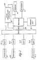
- FIG. 2 is a block diagram of some working parts of the present invention.
- FIG. 3 is a sample screen display according to the present invention.
- FIG. 1 shows an acoustic imager 10 according to the present invention.
- the imager has a keyboard 12 for inputting data and a screen 14 for communicating with the operator and for displaying images received by the imager.
- On either side of the keyboard is a tray 16 for supporting transducers 18.
- the transducers have a head 20 connected by a cord 22 to an input block 24.
- the input block mates with ports 26 on a lower panel of the ultrasonic imager. While it is preferred that the imager can support as many as four different transducers, it is not necessary that four be installed at any one time. In FIG. 1 only three transducers are installed, one in port 1, one in port 2 and one in port 4.
- the ultrasound imager is operated by, first, selecting a transducer for use, second, inputting this selection on the keyboard together with the desired performance parameters, for example, persistence, edge enhancement, compression, power output and image width, and, third, holding the transducer head over the body to be examined.
- the transducer emits high frequency sound waves which penetrate the surface of the body under examination and are reflected back to the transducer where they are detected. The detected sound waves are then converted into images.
- the apparatus described in US-A-5 121 361 the disclosure of which is hereby incorporated fully by reference herein, be used to produce and process the images.
- imaging can also be done using well known methods and equipment. Techniques for holding a transducer head to obtain the desired image are also largely well known in the art.
- the imager 10 can support transducers with a variety of transducer array configurations including linear arrays and curved linear arrays.
- FIG. 2 is a block diagram of some of the working parts of the ultrasound imager.
- the processor receives instructions from the keyboard 12 and transmits information to the display 14 where it can be read by the processor.
- the processor also has access to a memory unit 32.
- the bus, processor, display, keyboard and memory unit are all part of a control unit, which is responsible for driving the transducers and is housed in the main housing of the imager 10 shown in FIG. 1.
- the switching network 27 like the memory and display is controlled by the processor 30.
- the bus carries control signals from the processor to the switch in addition to carrying signals between the processor and the ports.
- the switch has a set of switches or relays which control which of the ports is coupled to the processor.
- FIG. 1 of US-A-5 121 361 shows a block diagram of an ultrasound imaging system into which the invention can be incorporated.
- the processor 30 and memory unit 32 herein are part of the main system processor 35
- bus 27 herein is part of bus 14
- keyboard 12 herein is part of control panel 39
- display 14 herein corresponds to the scan converter 36 and the video display terminal 38.
- the echoes received by the selected transducer are coupled by the corresponding port, switch 27, and bus 28 to echo processing circuitry 34, where signals are formed to operate display 14.
- the circuitry 34 is that disclosed in FIG. 1 of the referenced application.
- the signals generated by the processor 30 and the memory unit 32 to form the image of FIG. 3 herein are fed to the scan converter 36 and displayed on the screen of the video display terminal 38 of the referenced application.
- transducer selection start command into the keyboard. This instructs the processor to poll each of the ports 26-1 to 26-4 to determine if a transducer has been plugged into that port and, if so, what its attributes are. It is presently preferred that each transducer use multiple pin electric connectors to the ports. The polarity of three or four of the pins on each transducer input block 24 is hardwired to form an identification number. To poll each of the ports the processor operates the switch 27 to connect with each port one at a time. At each port it detects the identification number hardwired at the dedicated pins.
- Each identification number is then compared to a look-up table in the memory unit 32.
- the look-up table contains the attributes of the transducer as well as adjustable transducer operating parameters and instructions on how the transducer is to be driven.
- the memory unit 32 is preferably a hard disk drive or other rewriteable medium so that transducer identification numbers and transducer characteristics can be updated.
- the window 36 is preferably presented as an overlay to what is already being shown on the display and shows four separate boxes 38-1, 38-2, 38-3 and 38-4. Each box corresponds to one of the ports within the box.
- the attributes of the transducer installed into each port is displayed.
- the first box 38-1 displays three attributes of the transducer installed into port one, first, that it has an operating frequency of 7.5 megahertz (MHz), second, that it is a curved linear array (CLA), and third, that it is particularly suited to examining small parts (SP).
- the second box 38-2 shows that the transducer at that port has an operating frequency of 3.5 MHz, has an 85 millimeter head and also has a curved linear array (CLA).
- the third box 38-3 shows that the transducer at that port operates at 5.0 MHz and has a 60 mm CLA head.
- the fourth box shows "NO XDCR" meaning that no transducer has been installed into the fourth port.
- Any variety of different attributes can be chosen for display, for example, LF for long focus and PVLA for peripheral vascular linear array. Performance parameters as well as model numbers can be displayed in the box to assist the operator in choosing the appropriate transducer.
- the processor After the start command is received and the polling is completed, the processor presents the window shown in FIG. 3. The operator must then choose which transducer he will use. In FIG. 3, the third box is highlighted. This indicates that the third port having a 5.0 MHz, CLA transducer is selected.
- the indication associated with the third box can take any form; for example, cursors, underlining, flashing or color signals may be used.
- the selection of the third transducer can be changed in a variety of ways.
- the keyboard of FIG. 1 includes a convenient trackball 40. The transducer selection is altered by rolling the trackball. Rolling the trackball to the right moves the highlighter to the right and rolling the trackball to the left moves the highlighter to the left.
- a select button on the keyboard is pushed to confirm the selection. For example, starting with the screen in FIG. 3, if the operator wished to use the transducer plugged into the first port 7.5 MHz, he would roll the trackball to the left until the first box was highlighted. He would then push the select key, lift the transducer head out of its tray, and begin the examination.
- selection commands can be entered using cursor arrow keys. Beginning with the display shown in FIG. 3, the operator could push a left cursor arrow twice to highlight the first box and then push the select key. Other well known keyboard manipulation techniques may be used. The above two methods are preferred for their speed and simplicity.
- the imager drives that transducer conventionally or as described in US-A- 5 121 361 until a new selection is made.
- the operator keys a data acquisition command into the keyboard and the echo processing circuitry 34 becomes operative as described in the referenced application.
- the present invention makes it unnecessary to continuously remove and reinstall the desired transducer into a single port as required by most ultrasonic imaging machines. It also makes it unnecessary for the operator to remember the characteristics of two different transducers and which port each transducer has been plugged into as required by most multiple port machines.
- the key attributes of each transducer are displayed on the screen menu when the transducer selection is made.
- the present invention be integrated into an ultrasonic imager that allows the operator to select all of the operation parameters, for example depth setting, persistence, edge enhancement, compression, gray scale, power output and image width, using the keyboard based on displayed menus.
- the processor consults the memory immediately after a transducer port has been selected to obtain the adjustable operation parameters for the selected transducer. These are then displayed on the screen, and the user can adjust the parameters using the keyboard. The selected adjustments are displayed and, when all the adjustments are completed, the user enters a command causing the imager to start driving the selected transducer according to the selected operation parameter adjustments.
- the processor itself polls the ports to determine the identity of the transducers installed in each port, it is unnecessary to key in the attributes of the transducers as they are installed or even to know the transducer attributes before they are installed.
- the user simply installs the transducers, selects the transducer to be used first, based on the attributes shown on the display, sets the parameters of its operation, and begins the examination.
- the other transducers may be removed and replaced even during an examination because the ports are all polled before each selection to determine which transducers are resident there at the time of selection.
- the imager can also be adapted to poll the port being used periodically to confirm the identity of the transducer while it is being used. This allows the operator to switch transducers by unplugging the one being used and plugging a different transducer into the same port without returning to the keyboard.
Landscapes
- Engineering & Computer Science (AREA)
- Physics & Mathematics (AREA)
- Health & Medical Sciences (AREA)
- Life Sciences & Earth Sciences (AREA)
- Computer Networks & Wireless Communication (AREA)
- General Physics & Mathematics (AREA)
- Radar, Positioning & Navigation (AREA)
- Remote Sensing (AREA)
- Biomedical Technology (AREA)
- Animal Behavior & Ethology (AREA)
- Pathology (AREA)
- Radiology & Medical Imaging (AREA)
- Biophysics (AREA)
- Heart & Thoracic Surgery (AREA)
- Medical Informatics (AREA)
- Molecular Biology (AREA)
- Surgery (AREA)
- Nuclear Medicine, Radiotherapy & Molecular Imaging (AREA)
- General Health & Medical Sciences (AREA)
- Public Health (AREA)
- Veterinary Medicine (AREA)
- Acoustics & Sound (AREA)
- Multimedia (AREA)
- Ultra Sonic Daignosis Equipment (AREA)
- Investigating Or Analyzing Materials By The Use Of Ultrasonic Waves (AREA)
Description
- The present invention pertains to the field of ultrasound imaging and in particular to an ultrasonic diagnostic scanner capable of supporting multiple transducers.
- A variety of ultrasound imaging systems are well known in the art and are valuable for scanning and examining details below a surface. They are particularly useful in medical diagnosis because they allow real time imaging inside a patient's body without surgery and without penetration.
- A modern ultrasound imaging system will usually support a variety of different transducing heads. The transducing heads are responsible for actually transmitting the ultrasound signals and receiving the echoes from within the body being examined. Different heads are better suited to different applications. The depth of penetration, resolution and contrast, for example, can vary greatly from one head type to another.
- In a conventional ultrasound imaging system the head type is changed by unplugging one transducer head from a transducer port and then plugging a different head into the same port. In addition to being inconvenient, this arrangement causes interruptions in examinations which require that several different transducing heads be used.
- The present invention avoids this problem by supplying a plurality of ports into which transducing heads may be inserted at the same time. The attributes of each transducer may be displayed simultaneously on a screen and the operator need only manipulate a keyboard to select which transducer is to be used.
- In one embodiment, the invention is an ultrasonic imager with a plurality of ports, each capable of being connected to an ultrasonic transducer having a plurality of attributes. A control unit polls each port to determine the attributes of any connected transducers. The transducer attributes obtained from the poll are then shown on a display. The attributes may include the transmitting frequency of the transducer, the configuration array of the transducer head and model numbers. The control unit preferably polls each port to determine whether a transducer is connected to each port and displays this information as well.
- The control unit drives the transducers connected to the ports and preferably includes a selector for determining which of the transducers is to be driven. The transducer selector has a trackball coupled to an indicator on the display so that, through rolling the trackball, a transducer is selected by positioning the indicator proximate a displayed set of attributes corresponding to the transducer to be selected. Alternatively, the selector has a keyboard coupled to an indicator on the display so that, through keystrokes, a transducer is selected by positioning the indicator proximate a displayed set of attributes corresponding to the selected transducer. The transducers are replaceable and the display is changeable upon replacing a transducer. In another embodiment, the invention comprises an ultrasonic imager with a plurality of ultrasonic transducers for transmitting and receiving ultrasonic signals and converting the received ultrasonic signals to electrical signals, each transducer being independently operable and having a set of attributes. A control unit coupled with the transducers drives the transducers and receives the electrical signals. The control unit has a display for simultaneously displaying at least some of the attributes of each transducer and a selector for determining which transducers are to be driven. The display also indicates which, if any, of the transducers are being driven.
- FIG. 1 is a perspective view of an ultrasonic imager according to the present invention.
- FIG. 2 is a block diagram of some working parts of the present invention.
- FIG. 3 is a sample screen display according to the present invention.
- FIG. 1 shows an
acoustic imager 10 according to the present invention. The imager has akeyboard 12 for inputting data and ascreen 14 for communicating with the operator and for displaying images received by the imager. On either side of the keyboard is atray 16 for supportingtransducers 18. The transducers have ahead 20 connected by acord 22 to aninput block 24. The input block mates withports 26 on a lower panel of the ultrasonic imager. While it is preferred that the imager can support as many as four different transducers, it is not necessary that four be installed at any one time. In FIG. 1 only three transducers are installed, one in port 1, one inport 2 and one inport 4. - The ultrasound imager is operated by, first, selecting a transducer for use, second, inputting this selection on the keyboard together with the desired performance parameters, for example, persistence, edge enhancement, compression, power output and image width, and, third, holding the transducer head over the body to be examined. The transducer emits high frequency sound waves which penetrate the surface of the body under examination and are reflected back to the transducer where they are detected. The detected sound waves are then converted into images. It is presently preferred that the apparatus described in US-A-5 121 361, the disclosure of which is hereby incorporated fully by reference herein, be used to produce and process the images. However, imaging can also be done using well known methods and equipment. Techniques for holding a transducer head to obtain the desired image are also largely well known in the art. The
imager 10 can support transducers with a variety of transducer array configurations including linear arrays and curved linear arrays. - FIG. 2 is a block diagram of some of the working parts of the ultrasound imager. As in FIG. 1, there are three transducers 18-1, 18-2 18-4 plugged into three of the four ports 26-1 to 26-4. These ports connect to a shared
switching network 27 which connects to a sharedbus 28 and then to aprocessor 30. The processor receives instructions from thekeyboard 12 and transmits information to thedisplay 14 where it can be read by the processor. The processor also has access to amemory unit 32. The bus, processor, display, keyboard and memory unit are all part of a control unit, which is responsible for driving the transducers and is housed in the main housing of theimager 10 shown in FIG. 1. Theswitching network 27 like the memory and display is controlled by theprocessor 30. The bus carries control signals from the processor to the switch in addition to carrying signals between the processor and the ports. The switch has a set of switches or relays which control which of the ports is coupled to the processor. - Figure 1 of US-A-5 121 361 shows a block diagram of an ultrasound imaging system into which the invention can be incorporated. The disclosure of this application has been incorporated fully herein by reference. With reference to that figure, the
processor 30 andmemory unit 32 herein are part of the main system processor 35,bus 27 herein is part ofbus 14,keyboard 12 herein is part of control panel 39 and display 14 herein corresponds to thescan converter 36 and the video display terminal 38. In operation of the transducer selected in accordance with the invention, the echoes received by the selected transducer are coupled by the corresponding port,switch 27, andbus 28 toecho processing circuitry 34, where signals are formed to operatedisplay 14. Preferably, thecircuitry 34 is that disclosed in FIG. 1 of the referenced application. In terms of the invention, the signals generated by theprocessor 30 and thememory unit 32 to form the image of FIG. 3 herein are fed to thescan converter 36 and displayed on the screen of the video display terminal 38 of the referenced application. - When the operator wishes to begin an examination, he first must select a transducer to use. First, he keys a transducer selection start command into the keyboard. This instructs the processor to poll each of the ports 26-1 to 26-4 to determine if a transducer has been plugged into that port and, if so, what its attributes are. It is presently preferred that each transducer use multiple pin electric connectors to the ports. The polarity of three or four of the pins on each
transducer input block 24 is hardwired to form an identification number. To poll each of the ports the processor operates theswitch 27 to connect with each port one at a time. At each port it detects the identification number hardwired at the dedicated pins. Each identification number is then compared to a look-up table in thememory unit 32. The look-up table contains the attributes of the transducer as well as adjustable transducer operating parameters and instructions on how the transducer is to be driven. Thememory unit 32 is preferably a hard disk drive or other rewriteable medium so that transducer identification numbers and transducer characteristics can be updated. After polling each of the ports and comparing the identification number at each port to values in the look-up table, the processor produces the window of FIG. 3 in the display. - In FIG. 3, the
window 36 is preferably presented as an overlay to what is already being shown on the display and shows four separate boxes 38-1, 38-2, 38-3 and 38-4. Each box corresponds to one of the ports within the box. The attributes of the transducer installed into each port is displayed. The first box 38-1 displays three attributes of the transducer installed into port one, first, that it has an operating frequency of 7.5 megahertz (MHz), second, that it is a curved linear array (CLA), and third, that it is particularly suited to examining small parts (SP). The second box 38-2 shows that the transducer at that port has an operating frequency of 3.5 MHz, has an 85 millimeter head and also has a curved linear array (CLA). The third box 38-3 shows that the transducer at that port operates at 5.0 MHz and has a 60 mm CLA head. The fourth box shows "NO XDCR" meaning that no transducer has been installed into the fourth port. Any variety of different attributes can be chosen for display, for example, LF for long focus and PVLA for peripheral vascular linear array. Performance parameters as well as model numbers can be displayed in the box to assist the operator in choosing the appropriate transducer. - After the start command is received and the polling is completed, the processor presents the window shown in FIG. 3. The operator must then choose which transducer he will use. In FIG. 3, the third box is highlighted. This indicates that the third port having a 5.0 MHz, CLA transducer is selected. The indication associated with the third box can take any form; for example, cursors, underlining, flashing or color signals may be used. The selection of the third transducer can be changed in a variety of ways. The keyboard of FIG. 1 includes a
convenient trackball 40. The transducer selection is altered by rolling the trackball. Rolling the trackball to the right moves the highlighter to the right and rolling the trackball to the left moves the highlighter to the left. When the desired transducer is highlighted, a select button on the keyboard is pushed to confirm the selection. For example, starting with the screen in FIG. 3, if the operator wished to use the transducer plugged into the first port 7.5 MHz, he would roll the trackball to the left until the first box was highlighted. He would then push the select key, lift the transducer head out of its tray, and begin the examination. - Alternatively, selection commands can be entered using cursor arrow keys. Beginning with the display shown in FIG. 3, the operator could push a left cursor arrow twice to highlight the first box and then push the select key. Other well known keyboard manipulation techniques may be used. The above two methods are preferred for their speed and simplicity. After a transducer is selected, the imager drives that transducer conventionally or as described in US-A- 5 121 361 until a new selection is made. After the transducer has been selected, the operator keys a data acquisition command into the keyboard and the
echo processing circuitry 34 becomes operative as described in the referenced application. - The present invention makes it unnecessary to continuously remove and reinstall the desired transducer into a single port as required by most ultrasonic imaging machines. It also makes it unnecessary for the operator to remember the characteristics of two different transducers and which port each transducer has been plugged into as required by most multiple port machines. The key attributes of each transducer are displayed on the screen menu when the transducer selection is made. It is preferred that the present invention be integrated into an ultrasonic imager that allows the operator to select all of the operation parameters, for example depth setting, persistence, edge enhancement, compression, gray scale, power output and image width, using the keyboard based on displayed menus. Preferably the processor consults the memory immediately after a transducer port has been selected to obtain the adjustable operation parameters for the selected transducer. These are then displayed on the screen, and the user can adjust the parameters using the keyboard. The selected adjustments are displayed and, when all the adjustments are completed, the user enters a command causing the imager to start driving the selected transducer according to the selected operation parameter adjustments.
- Because the processor itself polls the ports to determine the identity of the transducers installed in each port, it is unnecessary to key in the attributes of the transducers as they are installed or even to know the transducer attributes before they are installed. The user simply installs the transducers, selects the transducer to be used first, based on the attributes shown on the display, sets the parameters of its operation, and begins the examination. The other transducers may be removed and replaced even during an examination because the ports are all polled before each selection to determine which transducers are resident there at the time of selection. Using the hard wired identification pins the imager can also be adapted to poll the port being used periodically to confirm the identity of the transducer while it is being used. This allows the operator to switch transducers by unplugging the one being used and plugging a different transducer into the same port without returning to the keyboard.
- While only a few embodiments have been discussed, the inventors in no way intend to limit their invention to these specific examples. A great variety of modifications and adaptations are possible within the spirit and scope of the present invention. For example, the screen displays may be significantly changed in appearance without detracting from the utility of the invention.
Claims (15)
- An ultrasonic imager comprising:
a plurality of ports each capable of being connected to an ultrasonic transducer having a plurality of attributes;
a control unit for polling each port to determine attributes of the transducer connected to each port; and
a display for displaying the transducer attributes obtained from the poll. - The imager of claim 1 wherein the displayed attributes comprise the emitted frequency of the transmitter.
- The imager of claim 1 wherein the displayed attributes comprise the transducer array configuration.
- The imager of claim 1 wherein the control unit also polls each port to determine whether a transducer is connected to each port and wherein the display displays whether a transducer is connected at each port.
- The imager of claim 1 wherein the control unit drives the transducers connected to the ports and wherein the control unit comprises a selector for determining which transducer is to be driven.
- The imager of claim 1 wherein the selector comprises a trackball for selecting a transducer, the trackball being in communication with an indicator on the display so that, through rolling the trackball, a transducer is selected by positioning the indicator proximate a displayed set of attributes corresponding to the selected transducer.
- The imager of claim 5 wherein the selector comprises a keyboard for selecting a transducer, the keyboard being in communication with an indicator on the display so that, through keystrokes, a transducer is selected by positioning the indicator proximate a displayed set of attributes corresponding to the selected transducer.
- An ultrasonic imager comprising:
a plurality of ultrasonic transducers for transmitting and receiving ultrasonic signals and converting the received ultrasonic signals to electrical signals, each transducer being independently operable and having a set of attributes; and
a control unit coupled to the transducers for driving the transducers and receiving the electrical signals, the control unit comprising:
a display for simultaneously displaying at least some of the attributes of each transducer and
a selector for determining which transducers are to be driven. - The imager of claim 8 wherein the displayed attributes comprise the transducer's transmitted frequency.
- The imager of claim 8 wherein the displayed attributes comprise the transducer's array configuration.
- The imager of claim 8 wherein the display indicates which, if any, of the transducers are being driven.
- The imager of claim 8 wherein the selector comprises a trackball for selecting a transducer, the trackball being coupled to an indicator on the display so that, through rolling the trackball. a transducer is selected by positioning the indicator proximate a displayed set of attributes corresponding to the selected transducer.
- The imager of claim 8 wherein the selector comprises a keyboard for selecting a transducer, the keyboard being in communication with an indicator on the display so that, through keystrokes, a transducer is selected by positioning the indicator proximate a displayed set of attributes corresponding to the selected transducer.
- The imager of claim 8 wherein the transducers are replaceable and the display is changeable upon replacing a transducer.
- The imager of claim 14 wherein the control unit polls the transducers to determine the displayed attributes and the control unit adjusts the display of attributes in response to the poll.
Applications Claiming Priority (2)
| Application Number | Priority Date | Filing Date | Title |
|---|---|---|---|
| US07/485,419 US5205175A (en) | 1990-02-27 | 1990-02-27 | Multiple transducer selector |
| US485419 | 1990-02-27 |
Publications (3)
| Publication Number | Publication Date |
|---|---|
| EP0451463A2 EP0451463A2 (en) | 1991-10-16 |
| EP0451463A3 EP0451463A3 (en) | 1993-01-20 |
| EP0451463B1 true EP0451463B1 (en) | 1995-12-13 |
Family
ID=23928087
Family Applications (1)
| Application Number | Title | Priority Date | Filing Date |
|---|---|---|---|
| EP91102165A Expired - Lifetime EP0451463B1 (en) | 1990-02-27 | 1991-02-15 | Multiple transducer selector |
Country Status (4)
| Country | Link |
|---|---|
| US (1) | US5205175A (en) |
| EP (1) | EP0451463B1 (en) |
| JP (1) | JP3004752B2 (en) |
| DE (1) | DE69115326T2 (en) |
Families Citing this family (30)
| Publication number | Priority date | Publication date | Assignee | Title |
|---|---|---|---|---|
| JP2683966B2 (en) * | 1991-08-20 | 1997-12-03 | 富士通株式会社 | Stack connection type ultrasonic probe, ultrasonic diagnostic apparatus, and ultrasonic diagnostic system |
| US5437178A (en) * | 1992-07-06 | 1995-08-01 | Kay-Ray/Sensall, Inc. | Controller for ultrasonic sensors |
| JP3631257B2 (en) * | 1992-08-28 | 2005-03-23 | オリンパス株式会社 | Electronic endoscope device |
| JPH07289553A (en) * | 1994-04-22 | 1995-11-07 | Hitachi Medical Corp | Ultrasonic tomography |
| US5520187A (en) * | 1994-11-25 | 1996-05-28 | General Electric Company | Ultrasonic probe with programmable multiplexer for imaging systems with different channel counts |
| US5744555A (en) * | 1994-11-25 | 1998-04-28 | Eastman Chemical Company | Process for the synthesis of elastomeric polypropylene |
| US5615678A (en) * | 1994-11-25 | 1997-04-01 | General Electric Company | Integral auto-selecting yoke/transducer connector for ultrasound transducer probe |
| US5891041A (en) * | 1996-11-27 | 1999-04-06 | Hitachi Medical Corporation | Ultrasonic imaging system adapted for use with ultrasonic probes having different center frequencies |
| WO1998026281A1 (en) * | 1996-12-10 | 1998-06-18 | Hitachi Construction Machinery Co., Ltd. | Ultrasonic tester and system for its management |
| DE19741361C1 (en) * | 1997-09-19 | 1999-04-15 | Siemens Ag | Ultrasonic instrument set for medical diagnosis or non |
| US5882310A (en) * | 1997-12-01 | 1999-03-16 | Acuson Corporation | Ultrasound transducer connector and multiport imaging system receptacle arrangement |
| US6051895A (en) * | 1998-04-17 | 2000-04-18 | Milltronics Ltd. | Electronic switch relay |
| GB2337117B (en) * | 1998-05-04 | 2001-04-04 | Csi Technology Inc | Digital ultrasonic monitoring system and method |
| US7534211B2 (en) * | 2002-03-29 | 2009-05-19 | Sonosite, Inc. | Modular apparatus for diagnostic ultrasound |
| US6629927B1 (en) | 2002-05-23 | 2003-10-07 | Koninklijke Philips Electronics N.V. | Diagnostic ultrasound system cart with integral cable supports |
| US6699190B2 (en) | 2002-05-23 | 2004-03-02 | Koninklijke Philips Electronics N.V. | Diagnostic ultrasound system cart with integral wrist pad |
| US6739197B2 (en) | 2002-05-23 | 2004-05-25 | Koninklijke Philips Electronics N.V. | Ultrasonic diagnostic imaging system with elevated and tilted scanhead connectors |
| US6821250B2 (en) | 2002-05-23 | 2004-11-23 | Koninklijke Philips Electronics N.V. | Diagnostic ultrasound system cart with movable probe holders |
| US6629928B1 (en) * | 2002-11-08 | 2003-10-07 | Koninklijke Philips Electronics N.V. | Modular transducer connection system |
| US7591786B2 (en) * | 2003-01-31 | 2009-09-22 | Sonosite, Inc. | Dock for connecting peripheral devices to a modular diagnostic ultrasound apparatus |
| US7806827B2 (en) * | 2003-03-11 | 2010-10-05 | General Electric Company | Ultrasound breast screening device |
| US6980419B2 (en) * | 2003-03-12 | 2005-12-27 | Zonare Medical Systems, Inc. | Portable ultrasound unit and docking station |
| US7278289B2 (en) * | 2003-04-28 | 2007-10-09 | Sonora Medical Systems, Inc. | Apparatus and methods for testing acoustic systems |
| US7031865B2 (en) * | 2003-08-06 | 2006-04-18 | Aquasensors Llc | Universal sensor adapter |
| EP2267482A1 (en) | 2003-11-26 | 2010-12-29 | Teratech Corporation | Modular portable ultrasound systems |
| US8488792B2 (en) * | 2005-10-26 | 2013-07-16 | Hewlett-Packard Development Company, L.P. | Wireless communications validation system and method |
| US7505363B2 (en) | 2006-04-10 | 2009-03-17 | Airmar Technology Corporation | Automatic switch for marine sounders |
| JP5601691B2 (en) * | 2011-07-28 | 2014-10-08 | ジーイー・メディカル・システムズ・グローバル・テクノロジー・カンパニー・エルエルシー | Ultrasonic image display device and control program thereof |
| JP5976472B2 (en) * | 2012-09-14 | 2016-08-23 | 東芝メディカルシステムズ株式会社 | Ultrasonic diagnostic apparatus and control program |
| US20140354606A1 (en) * | 2013-05-28 | 2014-12-04 | Himax Technologies Limited | Display Device for Displaying Images |
Family Cites Families (13)
| Publication number | Priority date | Publication date | Assignee | Title |
|---|---|---|---|---|
| JPS512774B1 (en) * | 1969-03-22 | 1976-01-28 | ||
| NL7907595A (en) * | 1979-10-15 | 1981-04-21 | Philips Nv | METHOD AND ARRANGEMENT OF RESEARCH WITH ULTRASONIC BUNDLES. |
| CA1158775A (en) * | 1980-06-04 | 1983-12-13 | Thomas L. Phinney | Computer annotation system |
| FR2517147A1 (en) * | 1981-11-25 | 1983-05-27 | Telecommunications Sa | DIGITAL OPTICAL PLURAL OPTICAL INFORMATION TRANSMISSION SYSTEM |
| JPS605136A (en) * | 1983-06-24 | 1985-01-11 | 株式会社日立製作所 | Ultrasonic tomography device |
| CA1214858A (en) * | 1984-09-27 | 1986-12-02 | Stanley Panton | Acoustic ranging system |
| US4751686A (en) * | 1985-05-14 | 1988-06-14 | Olympus Optical Co., Ltd. | Ultrasonic microscope |
| JPH0734797B2 (en) * | 1986-12-18 | 1995-04-19 | 株式会社日立メデイコ | Ultrasonic diagnostic equipment |
| JPH0185664U (en) * | 1987-11-27 | 1989-06-07 | ||
| JPH01300936A (en) * | 1988-05-30 | 1989-12-05 | Yokogawa Medical Syst Ltd | Ultrasonic diagnostic apparatus |
| JPH066805Y2 (en) * | 1988-08-26 | 1994-02-23 | 横河メディカルシステム株式会社 | Ultrasonic diagnostic equipment |
| JPH02237549A (en) * | 1989-03-10 | 1990-09-20 | Fuji Electric Co Ltd | Ultrasonic diagnostic apparatus |
| JP2967930B2 (en) * | 1989-05-12 | 1999-10-25 | 株式会社日立メディコ | Ultrasound diagnostic equipment |
-
1990
- 1990-02-27 US US07/485,419 patent/US5205175A/en not_active Expired - Lifetime
-
1991
- 1991-02-15 DE DE69115326T patent/DE69115326T2/en not_active Expired - Fee Related
- 1991-02-15 EP EP91102165A patent/EP0451463B1/en not_active Expired - Lifetime
- 1991-02-27 JP JP3056070A patent/JP3004752B2/en not_active Expired - Fee Related
Also Published As
| Publication number | Publication date |
|---|---|
| US5205175A (en) | 1993-04-27 |
| JP3004752B2 (en) | 2000-01-31 |
| JPH05220139A (en) | 1993-08-31 |
| EP0451463A2 (en) | 1991-10-16 |
| DE69115326T2 (en) | 1996-08-22 |
| EP0451463A3 (en) | 1993-01-20 |
| DE69115326D1 (en) | 1996-01-25 |
Similar Documents
| Publication | Publication Date | Title |
|---|---|---|
| US5205175A (en) | Multiple transducer selector | |
| US7022075B2 (en) | User interface for handheld imaging devices | |
| US20030013959A1 (en) | User interface for handheld imaging devices | |
| US6773398B2 (en) | Ultrasonic diagnosis apparatus and operation device | |
| US6645148B2 (en) | Ultrasonic probe including pointing devices for remotely controlling functions of an associated imaging system | |
| US6602194B2 (en) | Dual beamformer ultrasound system for 2D and 3D imaging | |
| JP4870749B2 (en) | Ultrasonic diagnostic imaging system set by probe firmware | |
| EP3335636B1 (en) | Probe apparatus, medical instrument comprising same, and control method of probe apparatus | |
| US20100217128A1 (en) | Medical diagnostic device user interface | |
| US20050113690A1 (en) | Methods and systems for providing portable device extended resources | |
| US6238341B1 (en) | Ultrasound probe having integrated user-operable function switch | |
| JP2006518252A (en) | System for use with a modular diagnostic ultrasound system | |
| US20110152685A1 (en) | Ultrasound diagnostic apparatus and method for controlling focus position of ultrasound diagnostic apparatus | |
| EP1978375A1 (en) | Ultrasound observation system and ultrasound observation method therefor | |
| JPH1156852A (en) | Ultrasonic probe | |
| JP2009285175A (en) | Ultrasonic diagnostic device | |
| WO2006111874A2 (en) | Portable ultrasonic diagnostic imaging system with docking station | |
| US6290649B1 (en) | Ultrasound position sensing probe | |
| EP1138262B1 (en) | Tomographic ultrasonic diagnostic apparatus | |
| JPH10248843A (en) | Ultrasound diagnostic equipment | |
| US20070016058A1 (en) | System and method for controlling ultrasound probe having multiple transducer arrays | |
| JP4879623B2 (en) | Ultrasonic diagnostic equipment | |
| JP2000325350A (en) | Ultrasound diagnostic equipment | |
| WO2006111872A2 (en) | Pc-based portable ultrasonic diagnostic imaging system | |
| EP1152693A1 (en) | Ultrasonic diagnostic imaging system with voice communication |
Legal Events
| Date | Code | Title | Description |
|---|---|---|---|
| PUAI | Public reference made under article 153(3) epc to a published international application that has entered the european phase |
Free format text: ORIGINAL CODE: 0009012 |
|
| AK | Designated contracting states |
Kind code of ref document: A2 Designated state(s): DE FR GB IT |
|
| PUAL | Search report despatched |
Free format text: ORIGINAL CODE: 0009013 |
|
| AK | Designated contracting states |
Kind code of ref document: A3 Designated state(s): DE FR GB IT |
|
| 17P | Request for examination filed |
Effective date: 19930623 |
|
| 17Q | First examination report despatched |
Effective date: 19950322 |
|
| GRAA | (expected) grant |
Free format text: ORIGINAL CODE: 0009210 |
|
| AK | Designated contracting states |
Kind code of ref document: B1 Designated state(s): DE FR GB IT |
|
| ET | Fr: translation filed | ||
| REF | Corresponds to: |
Ref document number: 69115326 Country of ref document: DE Date of ref document: 19960125 |
|
| ITF | It: translation for a ep patent filed | ||
| PLBE | No opposition filed within time limit |
Free format text: ORIGINAL CODE: 0009261 |
|
| STAA | Information on the status of an ep patent application or granted ep patent |
Free format text: STATUS: NO OPPOSITION FILED WITHIN TIME LIMIT |
|
| 26N | No opposition filed | ||
| PGFP | Annual fee paid to national office [announced via postgrant information from national office to epo] |
Ref country code: FR Payment date: 19990617 Year of fee payment: 9 |
|
| PGFP | Annual fee paid to national office [announced via postgrant information from national office to epo] |
Ref country code: GB Payment date: 19990621 Year of fee payment: 9 |
|
| PG25 | Lapsed in a contracting state [announced via postgrant information from national office to epo] |
Ref country code: GB Free format text: LAPSE BECAUSE OF NON-PAYMENT OF DUE FEES Effective date: 20000215 |
|
| GBPC | Gb: european patent ceased through non-payment of renewal fee |
Effective date: 20000215 |
|
| PG25 | Lapsed in a contracting state [announced via postgrant information from national office to epo] |
Ref country code: FR Free format text: LAPSE BECAUSE OF NON-PAYMENT OF DUE FEES Effective date: 20001031 |
|
| REG | Reference to a national code |
Ref country code: FR Ref legal event code: ST |
|
| PG25 | Lapsed in a contracting state [announced via postgrant information from national office to epo] |
Ref country code: IT Free format text: LAPSE BECAUSE OF NON-PAYMENT OF DUE FEES Effective date: 20050215 |
|
| PGFP | Annual fee paid to national office [announced via postgrant information from national office to epo] |
Ref country code: DE Payment date: 20080421 Year of fee payment: 18 |
|
| PG25 | Lapsed in a contracting state [announced via postgrant information from national office to epo] |
Ref country code: DE Free format text: LAPSE BECAUSE OF NON-PAYMENT OF DUE FEES Effective date: 20090901 |