EP0451169B1 - Hollow lightpipe and method for its manufacture - Google Patents
Hollow lightpipe and method for its manufacture Download PDFInfo
- Publication number
- EP0451169B1 EP0451169B1 EP90900557A EP90900557A EP0451169B1 EP 0451169 B1 EP0451169 B1 EP 0451169B1 EP 90900557 A EP90900557 A EP 90900557A EP 90900557 A EP90900557 A EP 90900557A EP 0451169 B1 EP0451169 B1 EP 0451169B1
- Authority
- EP
- European Patent Office
- Prior art keywords
- ribbon
- waveguide
- reflective
- forming
- tube
- Prior art date
- Legal status (The legal status is an assumption and is not a legal conclusion. Google has not performed a legal analysis and makes no representation as to the accuracy of the status listed.)
- Expired - Lifetime
Links
- 238000000034 method Methods 0.000 title claims abstract description 52
- 238000004519 manufacturing process Methods 0.000 title claims description 17
- 239000000758 substrate Substances 0.000 claims abstract description 57
- 238000000576 coating method Methods 0.000 claims abstract description 48
- 239000011248 coating agent Substances 0.000 claims abstract description 44
- 230000007935 neutral effect Effects 0.000 claims abstract description 12
- 238000007743 anodising Methods 0.000 claims abstract description 3
- 239000000463 material Substances 0.000 claims description 46
- 229910052751 metal Inorganic materials 0.000 claims description 10
- 239000002184 metal Substances 0.000 claims description 10
- 238000005452 bending Methods 0.000 claims description 9
- 238000002310 reflectometry Methods 0.000 claims description 8
- 238000003466 welding Methods 0.000 claims description 6
- 230000003287 optical effect Effects 0.000 claims description 5
- ZOKXTWBITQBERF-UHFFFAOYSA-N Molybdenum Chemical compound [Mo] ZOKXTWBITQBERF-UHFFFAOYSA-N 0.000 claims description 4
- DMFGNRRURHSENX-UHFFFAOYSA-N beryllium copper Chemical compound [Be].[Cu] DMFGNRRURHSENX-UHFFFAOYSA-N 0.000 claims description 4
- 239000011230 binding agent Substances 0.000 claims description 4
- 230000005540 biological transmission Effects 0.000 claims description 4
- 229910052750 molybdenum Inorganic materials 0.000 claims description 4
- 239000011733 molybdenum Substances 0.000 claims description 4
- 229910001220 stainless steel Inorganic materials 0.000 claims description 4
- 239000010935 stainless steel Substances 0.000 claims description 4
- 239000010409 thin film Substances 0.000 claims description 4
- 229910004366 ThF4 Inorganic materials 0.000 claims description 3
- FPHIOHCCQGUGKU-UHFFFAOYSA-L difluorolead Chemical compound F[Pb]F FPHIOHCCQGUGKU-UHFFFAOYSA-L 0.000 claims description 3
- 229910052958 orpiment Inorganic materials 0.000 claims description 3
- SBIBMFFZSBJNJF-UHFFFAOYSA-N selenium;zinc Chemical compound [Se]=[Zn] SBIBMFFZSBJNJF-UHFFFAOYSA-N 0.000 claims description 3
- 239000011888 foil Substances 0.000 claims description 2
- 238000005096 rolling process Methods 0.000 claims description 2
- 238000004804 winding Methods 0.000 claims description 2
- 238000009501 film coating Methods 0.000 claims 1
- 238000001771 vacuum deposition Methods 0.000 claims 1
- 239000002131 composite material Substances 0.000 abstract description 6
- 238000007738 vacuum evaporation Methods 0.000 abstract description 3
- 238000005229 chemical vapour deposition Methods 0.000 abstract description 2
- 238000010285 flame spraying Methods 0.000 abstract description 2
- 238000004544 sputter deposition Methods 0.000 abstract description 2
- 230000001737 promoting effect Effects 0.000 abstract 1
- 230000008018 melting Effects 0.000 description 3
- 238000002844 melting Methods 0.000 description 3
- 230000015572 biosynthetic process Effects 0.000 description 2
- 230000032798 delamination Effects 0.000 description 2
- 238000000151 deposition Methods 0.000 description 2
- 230000000694 effects Effects 0.000 description 2
- 239000000835 fiber Substances 0.000 description 2
- 238000004476 mid-IR spectroscopy Methods 0.000 description 2
- 238000001228 spectrum Methods 0.000 description 2
- RYGMFSIKBFXOCR-UHFFFAOYSA-N Copper Chemical compound [Cu] RYGMFSIKBFXOCR-UHFFFAOYSA-N 0.000 description 1
- ATJFFYVFTNAWJD-UHFFFAOYSA-N Tin Chemical compound [Sn] ATJFFYVFTNAWJD-UHFFFAOYSA-N 0.000 description 1
- 229910052782 aluminium Inorganic materials 0.000 description 1
- XAGFODPZIPBFFR-UHFFFAOYSA-N aluminium Chemical compound [Al] XAGFODPZIPBFFR-UHFFFAOYSA-N 0.000 description 1
- 238000013459 approach Methods 0.000 description 1
- 230000004323 axial length Effects 0.000 description 1
- 230000006835 compression Effects 0.000 description 1
- 238000007906 compression Methods 0.000 description 1
- 229910052802 copper Inorganic materials 0.000 description 1
- 239000010949 copper Substances 0.000 description 1
- 230000003811 curling process Effects 0.000 description 1
- 238000010586 diagram Methods 0.000 description 1
- 230000004907 flux Effects 0.000 description 1
- 239000011521 glass Substances 0.000 description 1
- 230000017525 heat dissipation Effects 0.000 description 1
- 238000010438 heat treatment Methods 0.000 description 1
- 238000012986 modification Methods 0.000 description 1
- 230000004048 modification Effects 0.000 description 1
- 231100000252 nontoxic Toxicity 0.000 description 1
- 230000003000 nontoxic effect Effects 0.000 description 1
- 230000005855 radiation Effects 0.000 description 1
- 229910052709 silver Inorganic materials 0.000 description 1
- 239000004332 silver Substances 0.000 description 1
Images


Classifications
-
- G—PHYSICS
- G02—OPTICS
- G02B—OPTICAL ELEMENTS, SYSTEMS OR APPARATUS
- G02B6/00—Light guides; Structural details of arrangements comprising light guides and other optical elements, e.g. couplings
- G02B6/02—Optical fibres with cladding with or without a coating
- G02B6/032—Optical fibres with cladding with or without a coating with non solid core or cladding
Definitions
- This invention relates to a method of making waveguides for high efficiency transmission of laser light having a desired wavelength and to waveguides manufactured by that method.
- EP-0 195 629 which is a family member of US-A- 4 652 083.
- the lightpipes should be flexible and ideally have a transmittivity greater than 90% per meter. Although, for some applications, the lightpipes may be as short as 25.4mm (1 inch), they should be manufacturable in lengths which exceed 1 meter and with an inner diameter of about 1 millimeter, and should be inexpensive, non-toxic, and easily manufactured. Lightpipes having such properties are suitable for numerous military, scientific, medical, and industrial applications.
- a method which comprises providing an elongated ribbon of a substrate material, said ribbon having first and second opposite longitudinal edges spaced apart by a substantially uniform width and first and second sides therebetween; forming a reflective surface on said first side; after forming said reflective surface, then bending said ribbon to position said first and second edges together to form a hollow tube, with said first side forming an interior surface of said tube; and holding said first and second edges together so as to obtain said hollow tube.
- Still another advantage of the present invention is to provide a method of manufacturing a hollow lightpipe from a very thin layer of substrate material, the substrate material being held in a tubular form by being placed within a surrounding tubular sleeve.
- the present invention provides waveguides for high efficiency transmission made according to the above-described methods.
- the waveguide comprises a hollow elongated tube made from an elongated bent ribbon having a longitudinal seam and an interior surface defining an elongated interior space through which the laser light is transmitted.
- the waveguide further comprises a reflective layer formed on the interior surface of the tube for reflecting the laser light incident thereon.
- the waveguide can comprise a hollow elongated bendable metal tube.
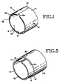
- Figure 1 is a fragmentary, perspective view of a first embodiment of the lightpipe of the present invention, showing a transverse cross section.
- Figure 2 is a transverse cross-sectional close-up view of a first embodiment of a longitudinally grooved ribbon, before it is bent transversely.
- Figure 3 is a transverse cross-sectional close-up view of the first embodiment of a longitudinally grooved ribbon shown in Figure 2, after the ribbon has been bent transversely.
- Figure 5 is a perspective view of a second embodiment of the lightpipe of the present invention, showing a transverse cross section.
- Figure 6 is a schematic depiction of one step of a first method of the present invention.
- Figure 7 is a schematic depiction of another step of the first method of the present invention.
- Figure 8 is a schematic depiction of yet another step of the first method of the present invention.
- Figure 9A is an isometric drawing of another step of a second method of the present invention.
- Figure 10 is a schematic depiction of a step in a third method of the present invention.
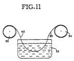
- Figure 11 is a schematic depiction of a step in a fourth method of the present invention.
- the interior surface 16 is highly reflective.
- the surface 16 must be coated with a reflective coating to form a reflective layer or surface 20 composed of a coating material having enhanced light reflective properties.
- the reflective coating can be a material with a refractive index having a low real part or a metal with a dielectric overcoat to enhance reflectivity. Classes of such materials are described in the above mentioned patent US-4 805 987 by Katherine D. Laakmann and Peter Laakmann, as well as U.S. Patent Nos. 4,652,083, 4,688,892, and 4,688,893.
- the coating material is first applied to the elongated ribbon 11 to form the reflective layer 20 and then the elongated ribbon is transversely bent or curled to create the tubular substrate structure 12.
- a binder layer 21 can be applied to the interior surface 16 before the reflective layer 20 is formed thereon. The binder layer 21 improves the adhesion of the reflective layer 20 to the interior surface 16.
- adhesion of the reflective layer 20 to the interior surface 16 of the tubular substrate structure 12 is of great importance, particularly since the reflective coating is generally applied on the elongated ribbon 11 while flat, before the ribbon is formed into the tubular shape by transversely curling it.
- curling the coated ribbon 11 into a small diameter tube, with an inside diameter in the size range of from about 0.5 millimeter to 1.5 millimeter places the reflective coating under considerable compressive forces. These forces tend to result in delamination of the reflective layer 20 from the elongated ribbon 11 of substrate material.
- Additional forces which tend to cause the reflective layer 20 to delaminate from the elongated ribbon result if the tubular substrate structure 12 is formed by passing the elongated ribbon through a conventional series of tube forming rollers such as shown in Figure 6 and described below. Additional delaminating forces result from differential thermal expansion between the substrate material comprising the tubular substrate structure 12 and the reflective coating comprising the reflective layer 20.
- Transversely curling the elongated ribbon 11 to form the tubular substrate structure 12 defines an imaginary, cylindrical neutral surface or axis, indicated by dashed line 22 in Figure 1, contained within the tubular substrate structure 12.
- this neutral surface 22 there are no tensile or compressive forces.
- Portions of the tubular substrate structure 12 which are radially inward of the neutral surface are placed in compression while those portions of the tubular substrate structure 12 which are radially outward of the neutral surface are placed in tension.
- the compressive forces at a point located radially inside the neutral surface 22 increase the more the point is radially inward from the neutral surface 22. Therefore, the reflective layer 20 is placed under higher compressive forces than adjacent portions of the tubular substrate structure 12. The closer the reflective layer 20 is located to the neutral surface 22, the less compressive stress it realizes.
- the neutral surface 22 is less than 0.0254mm (0.001 inch) from the reflective layer 20.
- the most direct way to minimize the distance the reflective layer 20 is located from the neutral surface 22 is to make the substrate material forming the elongated ribbon 11 quite thin, such as 0.0127 (0.0005) - 0.0254mm (0.001 inch). If the elongated ribbon 11 has a thickness in this range it may be too fragile to withstand the process of being formed into the tubular substrate structure 12. As such, it may be appropriate to form the elongated ribbon from a laminated composite. Such a composite elongated ribbon 11 consists of a thin inner layer of material having a high Young's modulus bonded to a thicker outer layer of material having a much lower Young's modulus. The reflective layer 20 is applied to the thin inner layer having the high Young's modulus.
- the reflective layer 20 is positioned fairly close to the neutral surface 22 and the compressive stress is reduced.
- the high Young's modulus of the thin inner layer lends springiness or resilience to the tubular structure 12.
- the low modulus and greater thickness of the outer layer of the tubular substrate structure 12 provides structural integrity and allows the tubular substrate structure 12 to be welded along the longitudinal seam 18.
- Appropriate materials for a laminated composite are molybdenum for the thinner inner layer in a thickness of 0.0127mm (0.0005 inch) and tin for the thicker outer layer in a thickness of 0.0762mm (0.003 inch).
- the outer material can also be chosen for its weldability.
- An alternative way of reducing the compressive stress in the reflective coating 20 is to form longitudinal grooves in the ribbon 11 before it is curled into its tubular form. This technique also mitigates any optical losses due to induced stress birefringence in the reflective coating 20.
- a plurality of longitudinal grooves 24 are formed on the second side 26 of the ribbon 11.
- the reflective coating 20 is formed over the first side 28.
- the grooves 24 substantially reduce the stress in the reflective coating 20 when the ribbon 11 is curled into a longitudinally tubular shape, as shown in the transverse cross-sectional close-up view of Figure 3.
- the reflective coating 20 can be applied to the first side 28 either before or after the grooves 24 are formed in the ribbon 11 but before the ribbon 11 is curled into its longitudinally tubular shape.
- the polygonal form of the tube which results from the grooving techniques described above offers no practical performance disadvantage as compared to a cylindrical waveguide. If the reflective coating 20 tends to delaminate along the bending lines 29, and the width of the delamination zone is intolerably wide, then the ribbon 11 can be longitudinally grooved as shown in Figure 4.
- Figure 4 shows the grooved ribbon 11 after it has been transversely curled to produce the hollow lightpipe 10.
- the grooves 24' (preferably having parallel sides and square bottoms when formed) are formed either before or after the reflective coating 20 is applied to the first side 28.
- the grooves 24' are formed in the first side 28 after the reflective coating 20 is applied, resulting separate segments of the reflective coating 20 close up tightly in a butting relationship when the ribbon 11 is transversely curled.
- the reflective coating 20 can be formed after the grooves 24' are formed in the first side 28 of the ribbon 11. If desired, a low-loss thin film dielectric coating 25 can be formed over the reflective coating 20.
- Another method of forming a composite elongated ribbon is to simultaneously roll a thin coated ribbon with a thicker ribbon placed therebelow to produce a thin-walled tube within a thick-walled tube.
- the outer thick-walled tube is welded in place around the inner thin-walled tube. This creates a reflective coating residing on a very thin substrate with low compressive stress, with the thin-walled tube encased within a more mechanically robust thick-walled tube.
- the methods described above tend to isolate the reflective layer 20 from the weld heat.
- the materials composing the two tubes can also be selected separately, to optimize the weldability of the thick-walled tube, for example.
- the coating material that is selected for the reflective layer 20 will not melt at incident flux levels of 5000 watts per square centimeter at angles of incidence of greater than 75 degrees.
- the lightpipe 10 can withstand at least 50 W of laser power with or without an enhanced reflective coating 20.
- the reflective coating comprising the reflective layer 20 will consist of a number of thin layers, the effects of thermal expansion can only be partially mitigated.
- the thick outer layer/tube should have a somewhat lower melting point and thermal conductivity than the thin inner layer/tube in order to enhance its weldability.
- the substrate material comprising the tubular substrate structure 12 and the reflective coating comprising the reflective layer 20 should be chosen not only for their desired optical properties, but also for their thermal and mechanical properties.
- Appropriate substrate materials for the tubular substrate structure 12 are molybdenum, beryllium copper, stainless steel, and aluminum. Reflective coatings of two types may be used. One type of reflective coating is described in the above-mentioned patent US-4 805 987 by Katherine D. Laakmann and Peter Laakmann. It is particularly desirable that the material forming the reflective layer 20 have a refractive index with a real part less than 0.2, in which event, the reflective layer 20 is especially suitable for use with a NdYAG laser, particularly when the reflective layer is made from a metal, such as silver or copper. Other types of reflective coatings are a high reflectivity metal coating with a dielectric overcoat to enhance reflectivity, as described in the abovementioned patents. Other materials appropriate for the reflective layer 20 are As2S3, PbF2, ZnSe, ZnS, and ThF4.
- tubular substrate structure 12 is contained within an outer sleeve 30 having an outer sleeve surface 32 and inner sleeve surface 34.
- the exterior surface 14 of tubular substrate structure 12 fits in close proximity to the inner sleeve surface 34 of the sleeve 30 and holds the opposite longitudinal edges 19a and 19b of the elongated ribbon 11 without welding.
- the hollow lightpipe 10 of Figure 5 can be manufactured in a number of ways using a continuous linear process. As shown in Figure 9A, one way is to place appropriate lengths of the tubular substrate structure 12 (e.g., a one meter length) in a larger diameter sleeve 30' made of a material which can then be drawn down to a smaller diameter to form the sleeve 30. Suitable materials are stainless steel and beryllium copper. After the tubular structure 12 is loosely in place within the large sleeve 30', the sleeve is drawn down until it forms the sleeve 30 and fits snugly around the tubular substrate structure 12 as shown in Figure 9B. In this manner, the longitudinal edges 19a and 19b of the tubular substrate structure 12 are drawn into contact and held there without the need for welding or the application of the intense heat associated with welding.
- appropriate lengths of the tubular substrate structure 12 e.g., a one meter length
- Suitable materials are stainless steel and beryllium copper.
- the reflective layer 20 be applied on the elongated ribbon 11 before the elongated ribbon is transversely curled into the shape of the tubular substrate structure 12.
- Figure 6 One step in a method for accomplishing this is shown in Figure 6. It consists of longitudinally winding the elongated ribbon 11 in a helical wind onto a cylindrical drum 42 with a smooth outer surface and having a diameter much greater than the thickness of the elongated ribbon 11. In this way, a first surface (not shown) of the elongated ribbon 11 which ultimately becomes the exterior surface 14 of the tubular substrate structure 12 is placed against an exterior surface 44 of the drum 42, while a second surface 11a of the elongated ribbon which ultimately becomes the interior surface 16 is facing outwardly.
- the reflective layer 20 is applied on the elongated ribbon 11.
- the drum 42 with the elongated ribbon 11 wound around its exterior surface 44, is placed in a coating chamber 45 of conventional type.
- a conventional process such as chemical vapor deposition, vacuum evaporation, sputtering, or flame spraying can be used to apply a thin film of reflective coating to the substrate material.
- vacuum evaporation it is important that the vapor stream of the material being deposited to form the reflective layer 20 strike the exposed second surface 11a of the elongated ribbon 11 at an approximately 90 degree angle.
- Figure 10 One means to accomplish this purpose is shown in Figure 10, where the elongated ribbon 11 is formed around a drum 42' having a flattened or oval cross-section.
- the outwardly facing second surfaces 11a of the elongated ribbon 11 wound on a first half 46 of the drum 42 can first be coated using a vapor stream generated from coating material 43 positioned therebelow and, subsequently, the drum can be rotated and the outwardly facing second surfaces 11a of the elongated ribbon wound on a second half 48 of the drum 42 can be coated.
- FIG. 11 An alternative method for continuously applying the reflective layer 20 on the elongated ribbon 11 is shown in Figure 11.
- the elongated ribbon 11 with the reflective layer 20 anodised is then wound to a takeup spool 54.
- the reflective layer 20 anodized onto the elongated ribbon 11 is anodized for enhanced reflectivity coating at wavelengths of about 10.6 nanometers.
- the schematic diagram of Figure 8 shows the formation of the tubular substrate structure 12 from the elongated ribbon 11, after elongated ribbon has had the reflective layer 20 applied thereon by one of the aforementioned processes.
- the elongated ribbon 11 After the elongated ribbon 11 has been coated with the reflective layer 20, it is wound onto a supply drum 60.
- the reflective layer 20 has been formed on the elongated ribbon 11 using the drum 42 of Figure 7 or the spool 50 of Figure 11, this drum or spool can serve as the supply drum 60.
- the coated elongated ribbon 11 is passed through a series of rollers 62, 64 and 66 which cause the elongated ribbon to transversely curl to form the tubular structure 12.
- the longitudinal seam 18 can be welded by a welding tool 68.
- the hollow lightpipe 20 via a continuous linear process capable of producing hundreds of meters of hollow lightpipe at a time. This is particularly appropriate for the formation of hollow lightpipes and other tubular structures requiring an inner, applied layer, since standard tube-forming rolling apparatus require substantial lengths (i.e., 50 meters or more) of ribbon length just to bring the apparatus in proper adjustment. Accordingly, since the hollow lightpipe 10 is typically used in approximately 1 meter lengths, the cost of a manufacturing run can be apportioned among a hundred or more lengths.
Landscapes
- Physics & Mathematics (AREA)
- General Physics & Mathematics (AREA)
- Optics & Photonics (AREA)
- Light Guides In General And Applications Therefor (AREA)
- Laminated Bodies (AREA)
- Optical Fibers, Optical Fiber Cores, And Optical Fiber Bundles (AREA)
- Blow-Moulding Or Thermoforming Of Plastics Or The Like (AREA)
- Illuminated Signs And Luminous Advertising (AREA)
- Lining Or Joining Of Plastics Or The Like (AREA)
Abstract
Description
- This invention relates to a method of making waveguides for high efficiency transmission of laser light having a desired wavelength and to waveguides manufactured by that method.
- A method and a waveguide manufactured by that method are known from EP-0 195 629, which is a family member of US-A- 4 652 083.
- The ability to transmit light through thin, flexible rods has many useful applications. In the visible light region of the optical light spectrum, this has been accomplished by low cost glass filament or plastic fibers. In the mid infra-red (IR) region of the spectrum, however, suitable fibers are difficult, if not impossible, to fabricate. Many workers have, therefore, focused their attention on hollow light guides, generally known as lightpipes.
- The lightpipes should be flexible and ideally have a transmittivity greater than 90% per meter. Although, for some applications, the lightpipes may be as short as 25.4mm (1 inch), they should be manufacturable in lengths which exceed 1 meter and with an inner diameter of about 1 millimeter, and should be inexpensive, non-toxic, and easily manufactured. Lightpipes having such properties are suitable for numerous military, scientific, medical, and industrial applications.
- A variety of approaches to the problem of developing such lightpipes have been taken, some meeting with limited success. There are several existing solid-type lightpipes relying on total internal reflection, but none of these has yet reached commercial realization. In the past, the methods of fabrication were capable of producing only relatively short lengths per manufacturing cycle, thus resulting in high cost per unit length. The hollow waveguide described by Katherine D. Laakmann in the U.S. Patent No. 4,652,083 is available commercially, but suffers from limited flexibility and length. It is also more difficult than desired to manufacture because of the difficulty in depositing one or more thin film layers of precise thickness onto the interior wall of a long narrow lightpipe which may have an inside diameter of 1.0 to 1.5 millimeter.
- In order for a hollow tube of approximately one meter length to transfer useful amounts of mid-IR radiation, it is necessary that the inner wall of the tube be coated with a reflection-enhancing material. This coating consists of one or more thin dielectric layers sometimes in combination with a thin layer of metal undercoating. Lightpipes having such coatings have been described in U.S. Patent 4 805 987 by Katherine D. Laakmann and Peter Laakmann, as well as U.S. Patent Nos. 4,652,083, 4,688,892, and 4,688,893.
- None of these coating methods, however, is conducive to depositing a coating directly on the inside of a long, narrow tube. It is therefore desirable to have an economical method of manufacturing hollow lightpipes having reflection-enhancing materials coated to their inner surfaces. In order to manufacture a low cost hollow lightpipe, it will be necessary to manufacture it via a continuous, linear process capable of producing hundreds of meters at a time. The resulting lightpipe should have the desirable characteristics noted above.
- It is an object of the present invention to provide an efficient method of manufacturing a hollow lightpipe having a reflection-enhancing material coated to its inner surface.
- This object is solved by a method which comprises providing an elongated ribbon of a substrate material, said ribbon having first and second opposite longitudinal edges spaced apart by a substantially uniform width and first and second sides therebetween; forming a reflective surface on said first side; after forming said reflective surface, then bending said ribbon to position said first and second edges together to form a hollow tube, with said first side forming an interior surface of said tube; and holding said first and second edges together so as to obtain said hollow tube.
- It is an advantage of the present invention to provide a method of manufacturing a hollow lightpipe from an elongated ribbon of substrate material.
- It is yet another advantage of the present invention to provide a method of manufacturing a hollow lightpipe including applying a coating of reflection-enhancing material to one surface of an elongated ribbon of substrate material prior to forming an elongated tube from the coated substrate.
- Still another advantage of the present invention is to provide a method of manufacturing a hollow lightpipe from a very thin layer of substrate material, the substrate material being held in a tubular form by being placed within a surrounding tubular sleeve.
- Furthermore, the present invention provides waveguides for high efficiency transmission made according to the above-described methods. The waveguide comprises a hollow elongated tube made from an elongated bent ribbon having a longitudinal seam and an interior surface defining an elongated interior space through which the laser light is transmitted. The waveguide further comprises a reflective layer formed on the interior surface of the tube for reflecting the laser light incident thereon. In one embodiment the waveguide can comprise a hollow elongated bendable metal tube.
- Figure 1 is a fragmentary, perspective view of a first embodiment of the lightpipe of the present invention, showing a transverse cross section.
- Figure 2 is a transverse cross-sectional close-up view of a first embodiment of a longitudinally grooved ribbon, before it is bent transversely.
- Figure 3 is a transverse cross-sectional close-up view of the first embodiment of a longitudinally grooved ribbon shown in Figure 2, after the ribbon has been bent transversely.
- Figure 4 is a transverse cross-sectional close-up view of a second embodiment of a longitudinally grooved ribbon, after the ribbon has been bent transversely.
- Figure 5 is a perspective view of a second embodiment of the lightpipe of the present invention, showing a transverse cross section.
- Figure 6 is a schematic depiction of one step of a first method of the present invention.
- Figure 7 is a schematic depiction of another step of the first method of the present invention.
- Figure 8 is a schematic depiction of yet another step of the first method of the present invention.
- Figure 9A is an isometric drawing of another step of a second method of the present invention.
- Figure 9B is an isometric drawing of a further step according to a second method of the present invention.
- Figure 10 is a schematic depiction of a step in a third method of the present invention.
- Figure 11 is a schematic depiction of a step in a fourth method of the present invention.
- Figure 1 is an isometric drawing of a first embodiment of a
hollow lightpipe 10 made according to the method of the present invention. Thehollow lightpipe 10 is made from a narrow, elongated flat foil or ribbon 11 (shown as such in the step of the manufacturing method illustrated in Figure 6) of a substrate material that has been formed into a cylindrical ortubular substrate structure 12 having anexterior surface 14 and aninterior surface 16. Thetubular substrate structure 12 can have any convenient cross-section, including circular and polygonal cross-sections. In one preferred embodiment, theelongated ribbon 11 has a thickness of about 0.0762mm (0.003 inch) or less. Thetubular substrate structure 12 includes alongitudinal seam 18 formed from an abutting arrangement of the oppositelongitudinal edges elongated ribbon 11 which are welded together. - The
interior surface 16 is highly reflective. In general, thesurface 16 must be coated with a reflective coating to form a reflective layer orsurface 20 composed of a coating material having enhanced light reflective properties. The reflective coating can be a material with a refractive index having a low real part or a metal with a dielectric overcoat to enhance reflectivity. Classes of such materials are described in the above mentioned patent US-4 805 987 by Katherine D. Laakmann and Peter Laakmann, as well as U.S. Patent Nos. 4,652,083, 4,688,892, and 4,688,893. In accordance with the inventive method, the coating material is first applied to theelongated ribbon 11 to form thereflective layer 20 and then the elongated ribbon is transversely bent or curled to create thetubular substrate structure 12. If desired, abinder layer 21 can be applied to theinterior surface 16 before thereflective layer 20 is formed thereon. Thebinder layer 21 improves the adhesion of thereflective layer 20 to theinterior surface 16. - In order to successfully manufacture the
hollow lightpipe 10 with thetubular substrate structure 12 shown in Figure 1, adhesion of thereflective layer 20 to theinterior surface 16 of thetubular substrate structure 12 is of great importance, particularly since the reflective coating is generally applied on theelongated ribbon 11 while flat, before the ribbon is formed into the tubular shape by transversely curling it. For use with mid-IR region light, curling thecoated ribbon 11 into a small diameter tube, with an inside diameter in the size range of from about 0.5 millimeter to 1.5 millimeter, places the reflective coating under considerable compressive forces. These forces tend to result in delamination of thereflective layer 20 from theelongated ribbon 11 of substrate material. Additional forces which tend to cause thereflective layer 20 to delaminate from the elongated ribbon result if thetubular substrate structure 12 is formed by passing the elongated ribbon through a conventional series of tube forming rollers such as shown in Figure 6 and described below. Additional delaminating forces result from differential thermal expansion between the substrate material comprising thetubular substrate structure 12 and the reflective coating comprising thereflective layer 20. - Transversely curling the
elongated ribbon 11 to form thetubular substrate structure 12 defines an imaginary, cylindrical neutral surface or axis, indicated bydashed line 22 in Figure 1, contained within thetubular substrate structure 12. Along thisneutral surface 22, there are no tensile or compressive forces. Portions of thetubular substrate structure 12 which are radially inward of the neutral surface are placed in compression while those portions of thetubular substrate structure 12 which are radially outward of the neutral surface are placed in tension. The compressive forces at a point located radially inside theneutral surface 22 increase the more the point is radially inward from theneutral surface 22. Therefore, thereflective layer 20 is placed under higher compressive forces than adjacent portions of thetubular substrate structure 12. The closer thereflective layer 20 is located to theneutral surface 22, the less compressive stress it realizes. In one preferred embodiment, theneutral surface 22 is less than 0.0254mm (0.001 inch) from thereflective layer 20. - The most direct way to minimize the distance the
reflective layer 20 is located from theneutral surface 22 is to make the substrate material forming theelongated ribbon 11 quite thin, such as 0.0127 (0.0005) - 0.0254mm (0.001 inch). If theelongated ribbon 11 has a thickness in this range it may be too fragile to withstand the process of being formed into thetubular substrate structure 12. As such, it may be appropriate to form the elongated ribbon from a laminated composite. Such a compositeelongated ribbon 11 consists of a thin inner layer of material having a high Young's modulus bonded to a thicker outer layer of material having a much lower Young's modulus. Thereflective layer 20 is applied to the thin inner layer having the high Young's modulus. Under these circumstances, when theelongated ribbon 11 is formed into thetubular substrate structure 12, thereflective layer 20 is positioned fairly close to theneutral surface 22 and the compressive stress is reduced. Also, the high Young's modulus of the thin inner layer lends springiness or resilience to thetubular structure 12. At the same time, the low modulus and greater thickness of the outer layer of thetubular substrate structure 12 provides structural integrity and allows thetubular substrate structure 12 to be welded along thelongitudinal seam 18. Appropriate materials for a laminated composite are molybdenum for the thinner inner layer in a thickness of 0.0127mm (0.0005 inch) and tin for the thicker outer layer in a thickness of 0.0762mm (0.003 inch). The outer material can also be chosen for its weldability. - An alternative way of reducing the compressive stress in the
reflective coating 20 is to form longitudinal grooves in theribbon 11 before it is curled into its tubular form. This technique also mitigates any optical losses due to induced stress birefringence in thereflective coating 20. As shown in the transverse cross-sectional close-up view of Figure 2, a plurality of longitudinal grooves 24 (for example, V-shaped grooves) are formed on thesecond side 26 of theribbon 11. Thereflective coating 20 is formed over thefirst side 28. Thegrooves 24 substantially reduce the stress in thereflective coating 20 when theribbon 11 is curled into a longitudinally tubular shape, as shown in the transverse cross-sectional close-up view of Figure 3. The reason is that all of the bending occurs at thegrooves 24 along bendinglines 29, sparing thereflective coating 20 from the compressive forces of the curling process. Thereflective coating 20 can be applied to thefirst side 28 either before or after thegrooves 24 are formed in theribbon 11 but before theribbon 11 is curled into its longitudinally tubular shape. - The polygonal form of the tube which results from the grooving techniques described above offers no practical performance disadvantage as compared to a cylindrical waveguide. If the
reflective coating 20 tends to delaminate along the bending lines 29, and the width of the delamination zone is intolerably wide, then theribbon 11 can be longitudinally grooved as shown in Figure 4. Figure 4 shows thegrooved ribbon 11 after it has been transversely curled to produce thehollow lightpipe 10. In this case, the grooves 24' (preferably having parallel sides and square bottoms when formed) are formed either before or after thereflective coating 20 is applied to thefirst side 28. If, as shown in Figure 4, the grooves 24' are formed in thefirst side 28 after thereflective coating 20 is applied, resulting separate segments of thereflective coating 20 close up tightly in a butting relationship when theribbon 11 is transversely curled. Alternatively, thereflective coating 20 can be formed after the grooves 24' are formed in thefirst side 28 of theribbon 11. If desired, a low-loss thinfilm dielectric coating 25 can be formed over thereflective coating 20. - Another method of forming a composite elongated ribbon is to simultaneously roll a thin coated ribbon with a thicker ribbon placed therebelow to produce a thin-walled tube within a thick-walled tube. As the tubes exit the forming rollers the outer thick-walled tube is welded in place around the inner thin-walled tube. This creates a reflective coating residing on a very thin substrate with low compressive stress, with the thin-walled tube encased within a more mechanically robust thick-walled tube. The methods described above tend to isolate the
reflective layer 20 from the weld heat. As described above, the materials composing the two tubes can also be selected separately, to optimize the weldability of the thick-walled tube, for example. - Other properties of the
elongated ribbon 11 that will affect the reflective coating adhesion, overall durability, and/or manufacturability of thehollow lightpipe 10 are: thermal conductivity, melting point, and coefficient of thermal expansion. The substrate material of thetubular substrate structure 12 adjacent to thereflective layer 20 should have good thermal conductivity for efficient heat dissipation, a high melting point to resist the effects of heating by a beam of laser light, and a coefficient of thermal expansion to optimize adhesion of the reflective coating comprising thereflective layer 20. Thehollow lightpipe 10 will be subjected to elevated temperatures during the process of forming thereflective layer 20, during any welding process used, and to a lesser extent, during use. In one preferred embodiment, the coating material that is selected for thereflective layer 20 will not melt at incident flux levels of 5000 watts per square centimeter at angles of incidence of greater than 75 degrees. In this embodiment, thelightpipe 10 can withstand at least 50 W of laser power with or without an enhancedreflective coating 20. - Differential thermal expansion between the
reflective layer 20 and the substrate material comprising thetubular substrate structure 12 will produce stresses. Since the reflective coating comprising thereflective layer 20 will consist of a number of thin layers, the effects of thermal expansion can only be partially mitigated. When using a composite structure as described previously, the thick outer layer/tube should have a somewhat lower melting point and thermal conductivity than the thin inner layer/tube in order to enhance its weldability. Also, since great differences exist among the optical coating materials and their ability to handle tensile and compressive forces, the substrate material comprising thetubular substrate structure 12 and the reflective coating comprising thereflective layer 20 should be chosen not only for their desired optical properties, but also for their thermal and mechanical properties. - Some relief from these undesired stresses within the structure of the
hollow lightpipe 10 can be had by fabricating thehollow lightpipe 10 to have somewhat larger inside diameter, such as in the size range of from 1.0 millimeter to 1.5 millimeter. While this is a practical solution since thereflective material 20 is not curled so tightly when thetubular substrate structure 12 is formed, it may only be used within certain limits, since beyond a certain size thehollow lightpipe 10 may not be usable for its intended purpose. The preferred range of outside diameters for thetubular substrate structure 12 is from 0.5 to 2.0 millimeters. - Appropriate substrate materials for the
tubular substrate structure 12 are molybdenum, beryllium copper, stainless steel, and aluminum. Reflective coatings of two types may be used. One type of reflective coating is described in the above-mentioned patent US-4 805 987 by Katherine D. Laakmann and Peter Laakmann. It is particularly desirable that the material forming thereflective layer 20 have a refractive index with a real part less than 0.2, in which event, thereflective layer 20 is especially suitable for use with a NdYAG laser, particularly when the reflective layer is made from a metal, such as silver or copper. Other types of reflective coatings are a high reflectivity metal coating with a dielectric overcoat to enhance reflectivity, as described in the abovementioned patents. Other materials appropriate for thereflective layer 20 are As₂S₃, PbF₂, ZnSe, ZnS, and ThF₄. - Referring now to the perspective view of Figure 5, an alternative structure for the
hollow lightpipe 10 is shown wherein it is not necessary to weld thelongitudinal seam 18. In thehollow lightpipe 10 of Figure 5, thetubular substrate structure 12 is contained within anouter sleeve 30 having anouter sleeve surface 32 andinner sleeve surface 34. Theexterior surface 14 oftubular substrate structure 12 fits in close proximity to theinner sleeve surface 34 of thesleeve 30 and holds the oppositelongitudinal edges elongated ribbon 11 without welding. - The
hollow lightpipe 10 of Figure 5 can be manufactured in a number of ways using a continuous linear process. As shown in Figure 9A, one way is to place appropriate lengths of the tubular substrate structure 12 (e.g., a one meter length) in a larger diameter sleeve 30' made of a material which can then be drawn down to a smaller diameter to form thesleeve 30. Suitable materials are stainless steel and beryllium copper. After thetubular structure 12 is loosely in place within the large sleeve 30', the sleeve is drawn down until it forms thesleeve 30 and fits snugly around thetubular substrate structure 12 as shown in Figure 9B. In this manner, thelongitudinal edges tubular substrate structure 12 are drawn into contact and held there without the need for welding or the application of the intense heat associated with welding. - The
hollow lightpipe 10 shown in Figure 5 can also be manufactured by first transversely curling thetubular substrate structure 12 so that it has a diameter smaller than that of thesleeve 30, then placing the tightly curledtubular substrate structure 12 into thesleeve 30, and allowing thetubular substrate structure 12 to relax and uncurl until itsexterior surface 14 is in close proximity to theinner sleeve surface 34 ofsleeve 30. - As mentioned above, it is necessary that the
reflective layer 20 be applied on theelongated ribbon 11 before the elongated ribbon is transversely curled into the shape of thetubular substrate structure 12. One step in a method for accomplishing this is shown in Figure 6. It consists of longitudinally winding theelongated ribbon 11 in a helical wind onto acylindrical drum 42 with a smooth outer surface and having a diameter much greater than the thickness of theelongated ribbon 11. In this way, a first surface (not shown) of theelongated ribbon 11 which ultimately becomes theexterior surface 14 of thetubular substrate structure 12 is placed against anexterior surface 44 of thedrum 42, while a second surface 11a of the elongated ribbon which ultimately becomes theinterior surface 16 is facing outwardly. By providing thedrum 42 with a diameter and axial length which are relatively large compared to the thickness and width of theelongated ribbon 11, long lengths of theelongated ribbon 11 can be wound onto theexterior surface 44 of even a moderately sized drum by turning the drum about an axis (not shown). Thedrum 42 can have a circular cross-section, as shown in Figure 8, or an oval cross-section, as shown in Figure 10. - Once the
elongated ribbon 11 is wound onto thedrum 42, thereflective layer 20 is applied on theelongated ribbon 11. As shown in Figure 7, thedrum 42, with theelongated ribbon 11 wound around itsexterior surface 44, is placed in acoating chamber 45 of conventional type. A conventional process such as chemical vapor deposition, vacuum evaporation, sputtering, or flame spraying can be used to apply a thin film of reflective coating to the substrate material. In some processes, such as vacuum evaporation, it is important that the vapor stream of the material being deposited to form thereflective layer 20 strike the exposed second surface 11a of theelongated ribbon 11 at an approximately 90 degree angle. One means to accomplish this purpose is shown in Figure 10, where theelongated ribbon 11 is formed around a drum 42' having a flattened or oval cross-section. In this way, the outwardly facing second surfaces 11a of theelongated ribbon 11 wound on a first half 46 of thedrum 42 can first be coated using a vapor stream generated from coatingmaterial 43 positioned therebelow and, subsequently, the drum can be rotated and the outwardly facing second surfaces 11a of the elongated ribbon wound on asecond half 48 of thedrum 42 can be coated. - An alternative method for continuously applying the
reflective layer 20 on theelongated ribbon 11 is shown in Figure 11. An uncoatedelongated ribbon 11 wound on asupply spool 50, is unwound and passed through ananodizing bath 52. Theelongated ribbon 11 with thereflective layer 20 anodised is then wound to atakeup spool 54. In one preferred embodiment, thereflective layer 20 anodized onto theelongated ribbon 11 is anodized for enhanced reflectivity coating at wavelengths of about 10.6 nanometers. - The schematic diagram of Figure 8 shows the formation of the
tubular substrate structure 12 from theelongated ribbon 11, after elongated ribbon has had thereflective layer 20 applied thereon by one of the aforementioned processes. After theelongated ribbon 11 has been coated with thereflective layer 20, it is wound onto asupply drum 60. Of course, if thereflective layer 20 has been formed on theelongated ribbon 11 using thedrum 42 of Figure 7 or thespool 50 of Figure 11, this drum or spool can serve as thesupply drum 60. The coatedelongated ribbon 11 is passed through a series ofrollers tubular structure 12. If desired, thelongitudinal seam 18 can be welded by awelding tool 68. Using the method shown in Figure 8, it is possible to fabricate thehollow lightpipe 20 via a continuous linear process capable of producing hundreds of meters of hollow lightpipe at a time. This is particularly appropriate for the formation of hollow lightpipes and other tubular structures requiring an inner, applied layer, since standard tube-forming rolling apparatus require substantial lengths (i.e., 50 meters or more) of ribbon length just to bring the apparatus in proper adjustment. Accordingly, since thehollow lightpipe 10 is typically used in approximately 1 meter lengths, the cost of a manufacturing run can be apportioned among a hundred or more lengths. - While several forms of the preferred embodiments of the hollow lightpipe of the invention and its inventive method of manufacture have been described in the foregoing, it will be understood by those skilled in the art that many modifications to the described process can be used without departing from the scope of the invention.
Claims (31)
- A method of making a hollow waveguide for high efficiency transmission of laser light having a desired wavelength, comprising the steps of:
providing an elongated ribbon (11) of a substrate material, said ribbon (11) having first and second opposite longitudinal edges (19a,19b) spaced apart by a substantially uniform width and first and second sides (16,14) therebetween;
forming a reflective surface (20) on said first side (16);
after forming said reflective surface (20), then bending said ribbon (11) to position said first and second edges (19a,19b) together to form a hollow tube, with said first side (16) forming an interior surface of said tube (12); and
holding said first and second edges (19a,19b) together so as to obtain said hollow tube. - The method of claim 1, further comprising the steps of:
providing a longitudinal sleeve (30); and
after bending said ribbon (11), positioning said bent ribbon (11) in said longitudinal sleeve (30) with an inside surface (34) of said longitudinal sleeve (30) engaging said second side (14) of said bent ribbon (11) to hold said first and second ribbon longitudinal edges (19a,19b) together. - The method of claim 2, wherein said longitudinal sleeve (30) initially has an interior diameter greater than an outer diameter of said bent ribbon (11), and the method further comprises the step of:
after positioning said bent ribbon (11) in said longitudinal sleeve (30), reducing the interior diameter of said longitudinal sleeve (30) to form a closely-fitting enclosure around said ribbon (11). - The method of claim 3, wherein said interior diameter of said longitudinal sleeve (30) is reduced by drawing down said longitudinal sleeve (30).
- The method of claim 1, wherein the step of forming said reflective surface comprises the steps of:
providing a support means;
placing said second side (14) of said ribbon (11) against said support means; and
applying a reflective coating (20) to said first side (16). - The method of claim 5, wherein said support means is a drum (42) having an axis which is larger than said width of said ribbon (11) and the step of applying said reflective coating (20) further comprises the step of turning said drum (42) about said axis, thereby winding said ribbon (11) longitudinally around said drum (42), thereby exposing said first side (16) of said ribbon (11) outwardly from said drum (42).
- The method of claim 6, wherein said drum (42) has two flattened sides and the step of applying said reflective coating (20) to said first side (16) is accomplished by vacuum deposition from a vapor stream having a direction that is substantially perpendicular to said sides (16).
- The method of claim 6, wherein said reflective surface (20) is formed by a high-reflectivity metal and a dielectric overcoat from one of a group of materials comprising As₂S₃, PbF₂, ZnSe, ZnS, and ThF₄, and the step of applying said reflective surface (20) to said first side further comprises the step of forming said reflective layer (20) with a thickness of approximately one-eighth of said wavelength of light.
- The method of claim 1, wherein said substrate material is made from molybdenum, beryllium copper, or stainless steel.
- The method of claim 1, wherein said substrate material has a thickness that is less than about 0.0762mm (0.003 inch).
- The method of claim 1, wherein the step of forming said reflective surface (20) comprises the steps of:
forming a binder coating on said first side (16); and
forming said reflective surface (20) over said binder coating. - The method of claim 1, further comprising the step of:
welding said first and second edges (19a,19b) together. - The method of claim 1, wherein the step of forming said reflective surface (20) is accomplished by anodizing said first side (16) for enhanced reflectivity at optical wavelengths of approximately 10.4 micrometers.
- The method of claim 1, further comprising the step of:
after forming said reflective surface (20), and prior to bending said ribbon (11), forming a plurality of longitudinal grooves (24) in said first side (16) of said ribbon (11), said grooves (24) extending through said reflective surface (20) and into said substrate material. - The method of claim 1, further comprising the step of:
after forming said reflective surface (20), and prior to bending said ribbon (11), forming a plurality of longitudinal grooves (24) in said second side (14) of said ribbon (11), said grooves (24) extending into said substrate material. - The method of claim 1, wherein the step of bending said ribbon (11) comprises the steps of:
providing a sleeve having a circular cross-section having a minimum inner diameter;
rolling said ribbon (11) into a tube (12) with a diameter less than said minimum inner diameter of said sleeve (30);
feeding said rolled elongated ribbon (11) into said sleeve (30); and
allowing said elongated ribbon (11) to expand within said sleeve (30). - A hollow waveguide for high efficiency transmission of laser light manufactured by a method according to one of claims 1 to 16, comprising:
a hollow elongated tube (12) made from an elongated ribbon (11) of a substrate material, said ribbon (11) having opposite longitudinal edges (19a,19b) and being transversely bent to place said opposite edges (19a,19b) in edge-to-edge relation to define a seam (18), said tube (12) also having an interior surface (16) defining an elongated interior space through which the laser light is to be transmitted; and
a reflective surface (20), formed on said interior surface (11) of said tube (12) for reflecting the laser light incident thereon. - The waveguide of claim 17, wherein said seam (18) is welded.
- The waveguide of claim 17, wherein said reflective layer (20) is a vacuum-deposited thin film coating.
- The waveguide of claim 17, wherein said reflective layer (20) includes a high reflectivity metal and a dielectric overcoat having one or more layers formed over said reflective layer (20).
- The waveguide of claim 20, wherein said dielectric overcoat has a thickness which is approximately one-eighth of said wavelength of said light incident on said reflective layer (20).
- The waveguide of claim 21, wherein said dielectric overcoat is formed from one of a group of materials comprising As₂S₃, PbF₂, ZnSe, ZnS, and ThF₄.
- The waveguide of claim 17, wherein said tube (12) has an exterior surface (14), the waveguide further comprising a housing having a first transverse cross section and surrounding said tube (12) in proximity to said exterior surface (14).
- The waveguide of claim 23, wherein said housing is a longitudinal sleeve (30) engaging said exterior surface (14) to hold said opposite edges (19a,19b) in said edge-to-edge relation.
- The waveguide of claim 23, wherein said housing has been drawn down to said first transverse cross section from a second transverse cross section larger than said first transverse cross section.
- The waveguide of claim 17, wherein said tube (12) is made from a foil having a thickness of less than about 0.0762mm (0.003 inch).
- The waveguide of claim 26, wherein said tube (12) is made from a material having a neutral surface which is less than approximately 0.0254mm (0.001 inch) from said reflective layer (30).
- The waveguide of claim 17, wherein said interior surface (16) has a transverse cross section which is substantially circular.
- The waveguide of claim 17, wherein said ribbon (11) comprises a metal and said reflective layer (20) consists of a dielectric overcoat on said metal to enhance reflectivity.
- The waveguide of claim 29, wherein said metal is selected from a group comprising molybdenum, beryllium copper, and stainless steel.
- The waveguide of claim 17, wherein said reflective layer of material has a complex index of refractivity with a real part (n) less than about 0.2.
Applications Claiming Priority (3)
| Application Number | Priority Date | Filing Date | Title |
|---|---|---|---|
| US277892 | 1988-11-29 | ||
| US07/277,892 US4913505A (en) | 1988-11-29 | 1988-11-29 | Hollow lightpipe and method for its manufacture |
| PCT/US1989/005383 WO1990006528A1 (en) | 1988-11-29 | 1989-11-28 | Hollow lightpipe and method for its manufacture |
Publications (2)
| Publication Number | Publication Date |
|---|---|
| EP0451169A1 EP0451169A1 (en) | 1991-10-16 |
| EP0451169B1 true EP0451169B1 (en) | 1994-06-08 |
Family
ID=23062824
Family Applications (1)
| Application Number | Title | Priority Date | Filing Date |
|---|---|---|---|
| EP90900557A Expired - Lifetime EP0451169B1 (en) | 1988-11-29 | 1989-11-28 | Hollow lightpipe and method for its manufacture |
Country Status (7)
| Country | Link |
|---|---|
| US (1) | US4913505A (en) |
| EP (1) | EP0451169B1 (en) |
| JP (1) | JPH04502070A (en) |
| AT (1) | ATE107040T1 (en) |
| CA (1) | CA2004087C (en) |
| DE (1) | DE68916039T2 (en) |
| WO (1) | WO1990006528A1 (en) |
Families Citing this family (29)
| Publication number | Priority date | Publication date | Assignee | Title |
|---|---|---|---|---|
| US5071222A (en) * | 1987-12-29 | 1991-12-10 | Luxar Corporation | Lightpipe tip for contact laser surgery |
| US5325458A (en) * | 1992-02-07 | 1994-06-28 | Surgilase, Inc. | Monolithic hollow waveguide and method and apparatus for making the same |
| IL105956A (en) * | 1993-06-08 | 1996-10-16 | Univ Ramot | Laser beam waveguide and laser beam delivery system including same |
| IL106302A (en) * | 1993-07-09 | 1996-12-05 | Univ Ramot | Hollow waveguide tips for controlling beam divergency and methods of making such tips |
| US5440664A (en) * | 1994-01-13 | 1995-08-08 | Rutgers, The State University Of New Jersey | Coherent, flexible, coated-bore hollow-fiber waveguide |
| US5815627A (en) * | 1994-01-13 | 1998-09-29 | Rutgers, The State University Of New Jersey | Co-axial hollow core waveguide |
| US6080467A (en) * | 1995-06-26 | 2000-06-27 | 3M Innovative Properties Company | High efficiency optical devices |
| US6117128A (en) * | 1997-04-30 | 2000-09-12 | Kenton W. Gregory | Energy delivery catheter and method for the use thereof |
| US6141476A (en) * | 1998-01-05 | 2000-10-31 | Matsuura; Yuji | Hollow waveguide for ultraviolet light and making the same |
| US6290668B1 (en) | 1998-04-30 | 2001-09-18 | Kenton W. Gregory | Light delivery catheter and methods for the use thereof |
| US6646635B2 (en) * | 2001-01-19 | 2003-11-11 | 3Com Corporation | Stylus apparatus and method for transmitting light |
| DE10143134A1 (en) * | 2001-09-03 | 2003-04-03 | Schott Glas | light integrator |
| US6870128B2 (en) | 2002-06-10 | 2005-03-22 | Japan Drilling Co., Ltd. | Laser boring method and system |
| US7079739B1 (en) | 2003-11-28 | 2006-07-18 | Peter Vitruk | Flexible hollow waveguide and method for its manufacture |
| US7331954B2 (en) | 2004-04-08 | 2008-02-19 | Omniguide, Inc. | Photonic crystal fibers and medical systems including photonic crystal fibers |
| US7349589B2 (en) * | 2004-04-08 | 2008-03-25 | Omniguide, Inc. | Photonic crystal fibers and medical systems including photonic crystal fibers |
| US7167622B2 (en) * | 2004-04-08 | 2007-01-23 | Omniguide, Inc. | Photonic crystal fibers and medical systems including photonic crystal fibers |
| US7664356B2 (en) * | 2004-05-21 | 2010-02-16 | Hitachi Cable, Ltd. | Hollow waveguide and method of manufacturing the same |
| US7180779B2 (en) * | 2005-07-11 | 2007-02-20 | Atmel Corporation | Memory architecture with enhanced over-erase tolerant control gate scheme |
| TW200827852A (en) * | 2006-12-28 | 2008-07-01 | Ind Tech Res Inst | Coupling device |
| TW200841512A (en) * | 2007-04-12 | 2008-10-16 | Univ Nat Central | Hollow waveguide formed by cyclic polygonal and circular structure |
| US8601815B2 (en) * | 2007-08-06 | 2013-12-10 | University Of Central Florida Research Foundation, Inc. | Method for generating, transmitting and receiving power |
| US8324543B2 (en) * | 2009-12-02 | 2012-12-04 | Raytheon Company | Lightpipe for semi-active laser target designation |
| US9063299B2 (en) | 2009-12-15 | 2015-06-23 | Omni Guide, Inc. | Two-part surgical waveguide |
| BR112015011876A2 (en) * | 2013-03-26 | 2017-07-11 | Halliburton Energy Services Inc | optical light tube and method for transmitting electromagnetic radiation in an optical light tube |
| WO2018045461A1 (en) * | 2016-09-07 | 2018-03-15 | Atomic Energy Of Canada Limited / Énergie Atomique Du Canada Limitée | Detection apparatus and method |
| US11491048B2 (en) | 2018-06-07 | 2022-11-08 | 3M Innovative Properties Company | Radiative warming system |
| WO2021029855A1 (en) * | 2019-08-09 | 2021-02-18 | Halliburton Energy Services, Inc. | Light pipe for logging-while-drilling communications |
| JP7686271B2 (en) * | 2021-07-01 | 2025-06-02 | 株式会社ニューロライテック | How to make a light irradiation device |
Family Cites Families (8)
| Publication number | Priority date | Publication date | Assignee | Title |
|---|---|---|---|---|
| GB984482A (en) * | 1963-01-03 | 1965-02-24 | Lucas Industries Ltd | Method of manufacturing waveguides |
| US4068920A (en) * | 1976-08-20 | 1978-01-17 | University Of Southern California | Flexible wave guide for laser light transmission |
| US4652083A (en) * | 1985-03-18 | 1987-03-24 | Laakmann Electro-Optics, Inc. | Hollow waveguide |
| US4688892A (en) * | 1985-03-18 | 1987-08-25 | Laakmann Electro-Optics, Inc. | Hollow waveguides having disparate dielectric overcoatings |
| US4688893A (en) * | 1985-03-18 | 1987-08-25 | Laakmann Electro-Optics, Inc. | Hollow waveguide having plural layer dielectric |
| GB2199960B (en) * | 1986-10-09 | 1990-06-06 | Medical Laser Unit | A flexible guide for infra-red energy |
| US4806289A (en) * | 1987-01-16 | 1989-02-21 | The Dow Chemical Company | Method of making a hollow light pipe |
| US4805987A (en) * | 1987-12-29 | 1989-02-21 | Laakmann Katherine D | Hollow lightpipe using a low refractive index inner layer |
-
1988
- 1988-11-29 US US07/277,892 patent/US4913505A/en not_active Expired - Lifetime
-
1989
- 1989-11-28 AT AT90900557T patent/ATE107040T1/en not_active IP Right Cessation
- 1989-11-28 JP JP2500773A patent/JPH04502070A/en active Pending
- 1989-11-28 EP EP90900557A patent/EP0451169B1/en not_active Expired - Lifetime
- 1989-11-28 WO PCT/US1989/005383 patent/WO1990006528A1/en not_active Ceased
- 1989-11-28 CA CA002004087A patent/CA2004087C/en not_active Expired - Fee Related
- 1989-11-28 DE DE68916039T patent/DE68916039T2/en not_active Expired - Fee Related
Also Published As
| Publication number | Publication date |
|---|---|
| JPH04502070A (en) | 1992-04-09 |
| DE68916039T2 (en) | 1994-09-29 |
| CA2004087A1 (en) | 1990-05-29 |
| ATE107040T1 (en) | 1994-06-15 |
| DE68916039D1 (en) | 1994-07-14 |
| CA2004087C (en) | 1994-05-17 |
| WO1990006528A1 (en) | 1990-06-14 |
| US4913505A (en) | 1990-04-03 |
| EP0451169A1 (en) | 1991-10-16 |
Similar Documents
| Publication | Publication Date | Title |
|---|---|---|
| US4913505A (en) | Hollow lightpipe and method for its manufacture | |
| Matsuura et al. | Optical properties of small-bore hollow glass waveguides | |
| US4652083A (en) | Hollow waveguide | |
| Fink et al. | Guiding optical light in air using an all-dielectric structure | |
| US5005944A (en) | Hollow lightpipe and lightpipe tip using a low refractive index inner layer | |
| Hongo et al. | Transmission of kilowatt-class CO2 laser light through dielectric-coated metallic hollow waveguides for material processing | |
| GB2288469A (en) | Optical hollow waveguide, its fabrication and laser transmission apparatus using it | |
| US4805987A (en) | Hollow lightpipe using a low refractive index inner layer | |
| Kozodoy et al. | Small-bore hollow waveguides for delivery of 3-μm laser radiation | |
| CN113376732B (en) | Intermediate infrared hollow waveguide and manufacturing method thereof | |
| Hongo et al. | Fabrication of dielectric-coated silver hollow glass waveguides for the infrared by liquid-flow coating method | |
| US7079739B1 (en) | Flexible hollow waveguide and method for its manufacture | |
| Machida et al. | Transmission properties of rectangular hollow waveguides for CO2 laser light | |
| Kato et al. | Fabrication of nontoxic and durable fluorocarbon-coated silver waveguides for the infrared: a new approach | |
| Kato et al. | New fabrication technique of fluorocarbon polymer-coated hollow waveguides by liquid-phase coating for medical applications | |
| Kato et al. | Transmission characteristics of polyimide-coated silver hollow glass waveguides for medical applications | |
| JP2021132755A (en) | Optical fiber probe | |
| US12196951B2 (en) | Optomechanical fiber actuator | |
| EP0903593B1 (en) | Striated light diffuser and method of forming the same | |
| AU619103B2 (en) | Striated light diffuser and method of forming the same | |
| RU1770936C (en) | Flexible hollow light guide manufacturing method | |
| Matsuura et al. | Infrared hollow glass fiber produced by fiber drawing technique | |
| Komachi et al. | Fabrication of hollow waveguides for CO2 lasers | |
| Matsuura et al. | Hollow fiber beam delivery systems | |
| Matsuura et al. | ZnSe-coated Ag waveguide for CO2 laser light transmission |
Legal Events
| Date | Code | Title | Description |
|---|---|---|---|
| PUAI | Public reference made under article 153(3) epc to a published international application that has entered the european phase |
Free format text: ORIGINAL CODE: 0009012 |
|
| 17P | Request for examination filed |
Effective date: 19910529 |
|
| AK | Designated contracting states |
Kind code of ref document: A1 Designated state(s): AT BE CH DE ES FR GB IT LI LU NL SE |
|
| 17Q | First examination report despatched |
Effective date: 19921120 |
|
| GRAA | (expected) grant |
Free format text: ORIGINAL CODE: 0009210 |
|
| AK | Designated contracting states |
Kind code of ref document: B1 Designated state(s): AT BE CH DE ES FR GB IT LI LU NL SE |
|
| PG25 | Lapsed in a contracting state [announced via postgrant information from national office to epo] |
Ref country code: NL Effective date: 19940608 Ref country code: LI Effective date: 19940608 Ref country code: ES Free format text: THE PATENT HAS BEEN ANNULLED BY A DECISION OF A NATIONAL AUTHORITY Effective date: 19940608 Ref country code: CH Effective date: 19940608 Ref country code: BE Effective date: 19940608 Ref country code: AT Effective date: 19940608 |
|
| REF | Corresponds to: |
Ref document number: 107040 Country of ref document: AT Date of ref document: 19940615 Kind code of ref document: T |
|
| ITF | It: translation for a ep patent filed | ||
| REF | Corresponds to: |
Ref document number: 68916039 Country of ref document: DE Date of ref document: 19940714 |
|
| PG25 | Lapsed in a contracting state [announced via postgrant information from national office to epo] |
Ref country code: SE Effective date: 19940908 |
|
| REG | Reference to a national code |
Ref country code: CH Ref legal event code: PL |
|
| ET | Fr: translation filed | ||
| NLV1 | Nl: lapsed or annulled due to failure to fulfill the requirements of art. 29p and 29m of the patents act | ||
| PG25 | Lapsed in a contracting state [announced via postgrant information from national office to epo] |
Ref country code: LU Free format text: LAPSE BECAUSE OF NON-PAYMENT OF DUE FEES Effective date: 19941130 |
|
| PLBE | No opposition filed within time limit |
Free format text: ORIGINAL CODE: 0009261 |
|
| STAA | Information on the status of an ep patent application or granted ep patent |
Free format text: STATUS: NO OPPOSITION FILED WITHIN TIME LIMIT |
|
| 26N | No opposition filed | ||
| PGFP | Annual fee paid to national office [announced via postgrant information from national office to epo] |
Ref country code: FR Payment date: 19981030 Year of fee payment: 10 |
|
| PGFP | Annual fee paid to national office [announced via postgrant information from national office to epo] |
Ref country code: GB Payment date: 19981102 Year of fee payment: 10 |
|
| PGFP | Annual fee paid to national office [announced via postgrant information from national office to epo] |
Ref country code: DE Payment date: 19981103 Year of fee payment: 10 |
|
| PG25 | Lapsed in a contracting state [announced via postgrant information from national office to epo] |
Ref country code: GB Free format text: LAPSE BECAUSE OF NON-PAYMENT OF DUE FEES Effective date: 19991128 |
|
| GBPC | Gb: european patent ceased through non-payment of renewal fee |
Effective date: 19991128 |
|
| PG25 | Lapsed in a contracting state [announced via postgrant information from national office to epo] |
Ref country code: FR Free format text: LAPSE BECAUSE OF NON-PAYMENT OF DUE FEES Effective date: 20000731 |
|
| PG25 | Lapsed in a contracting state [announced via postgrant information from national office to epo] |
Ref country code: DE Free format text: LAPSE BECAUSE OF NON-PAYMENT OF DUE FEES Effective date: 20000901 |
|
| REG | Reference to a national code |
Ref country code: FR Ref legal event code: ST |
|
| PG25 | Lapsed in a contracting state [announced via postgrant information from national office to epo] |
Ref country code: IT Free format text: LAPSE BECAUSE OF NON-PAYMENT OF DUE FEES;WARNING: LAPSES OF ITALIAN PATENTS WITH EFFECTIVE DATE BEFORE 2007 MAY HAVE OCCURRED AT ANY TIME BEFORE 2007. THE CORRECT EFFECTIVE DATE MAY BE DIFFERENT FROM THE ONE RECORDED. Effective date: 20051128 |