EP0451122A2 - Roll angle determination - Google Patents
Roll angle determination Download PDFInfo
- Publication number
- EP0451122A2 EP0451122A2 EP91850054A EP91850054A EP0451122A2 EP 0451122 A2 EP0451122 A2 EP 0451122A2 EP 91850054 A EP91850054 A EP 91850054A EP 91850054 A EP91850054 A EP 91850054A EP 0451122 A2 EP0451122 A2 EP 0451122A2
- Authority
- EP
- European Patent Office
- Prior art keywords
- projectile
- windings
- arrangement according
- barrel
- roll angle
- Prior art date
- Legal status (The legal status is an assumption and is not a legal conclusion. Google has not performed a legal analysis and makes no representation as to the accuracy of the status listed.)
- Granted
Links
- 238000004804 winding Methods 0.000 claims abstract description 29
- 238000011156 evaluation Methods 0.000 claims abstract description 8
- 238000010304 firing Methods 0.000 claims abstract description 4
- 238000005096 rolling process Methods 0.000 claims description 2
- 230000005855 radiation Effects 0.000 description 5
- 230000001419 dependent effect Effects 0.000 description 3
- 238000005259 measurement Methods 0.000 description 3
- 230000001133 acceleration Effects 0.000 description 2
- 230000005540 biological transmission Effects 0.000 description 2
- 238000012937 correction Methods 0.000 description 2
- 239000002360 explosive Substances 0.000 description 2
- 239000000463 material Substances 0.000 description 2
- 230000004075 alteration Effects 0.000 description 1
- 239000003990 capacitor Substances 0.000 description 1
- 230000008878 coupling Effects 0.000 description 1
- 238000010168 coupling process Methods 0.000 description 1
- 238000005859 coupling reaction Methods 0.000 description 1
- 238000009795 derivation Methods 0.000 description 1
- 238000013461 design Methods 0.000 description 1
- 238000006073 displacement reaction Methods 0.000 description 1
- 230000005670 electromagnetic radiation Effects 0.000 description 1
- 230000004907 flux Effects 0.000 description 1
- 239000000696 magnetic material Substances 0.000 description 1
- 238000000034 method Methods 0.000 description 1
- 238000012545 processing Methods 0.000 description 1
- 238000005070 sampling Methods 0.000 description 1
- 230000035939 shock Effects 0.000 description 1
- 229910000859 α-Fe Inorganic materials 0.000 description 1
Images


Classifications
-
- F—MECHANICAL ENGINEERING; LIGHTING; HEATING; WEAPONS; BLASTING
- F41—WEAPONS
- F41G—WEAPON SIGHTS; AIMING
- F41G7/00—Direction control systems for self-propelled missiles
- F41G7/20—Direction control systems for self-propelled missiles based on continuous observation of target position
- F41G7/30—Command link guidance systems
- F41G7/301—Details
- F41G7/305—Details for spin-stabilized missiles
Definitions
- the present invention relates to an arrangement for determining the roll angle of a rotating projectile, missile or the like by magnetic means as it leaves the barrel, launch tube or the like.
- the invention is applicable to all types of projectiles, missiles or the like which are fired from a barrel or launch tube and which rotate in their trajectory.
- the invention can be used in particular in so-called terminal-stage-guided ammunition, i.e. projectiles which are fired in a conventional manner in a ballistic trajectory to the immediate vicinity of the target, where they receive a command for necessary correction. Due to the fact that the projectile rotates in its trajectory, its roll position must be determined when the command is executed. In the absence of members for determining the roll position, an error otherwise occurs in the course correction.
- the abovementioned arrangement presupposes that a transmitter is placed in connection with the launching position of the projectile and that the projectile is provided with a rearward-directed receiving antenna in order to receive the transmitted radiation.
- the aim of this invention is to provide an alternative to the methods described above for roll angle determination, in which the determination is carried out by magnetic means instead of with transmitted microwave radiation, and without being dependent on the earth's magnetic field.
- the way this has been achieved emerges from the characterising clause of Patent Claim 1.
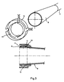
- Figure 1 shows a projectile (ballistic high-explosive shell) provided with a permanent magnet
- Figure 2 shows the magnetic field orientation
- Figure 3 shows a gun barrel with muzzle bell provided with two pairs of windings
- Figure 4 shows diagrammatically how an induced voltage is generated as the projectile passes the windings
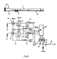
- Figure 5 shows an example of an evaluation unit for the sensor signals.
- Figure 1 shows a projectile in the form of a ballistic high-explosive shell 1, intended to be fired in a conventional manner from a barrel.
- a circular permanent magnet 2 is mounted in a wedge-shaped groove 3 in the nose cone casing of the shell in such a way that the magnetic field is oriented transverse to the longitudinal direction 4 of the shell, see Figure 2.
- the position of the permanent magnet 2 is chosen by taking into consideration the temperature stresses and acceleration stresses.
- the magnet can be of ferrite material and magnetised upon assembly. The magnet is assembled in a fixed position in the rolling plane so that correct angle information will be obtained (see below), in which respect an antenna in the rear plane of the shell may constitute a reference.
- Two non-magnetic rings 5, 6 are arranged in front of and behind the permanent magnet.
- the shell is in other respects conventional and is therefore not described in greater detail.
- the mouth of the gun barrel 7 is equipped with a muzzle bell 8 in the form of a truncated cone.
- Two pairs of windings 9, 10 are mounted on the outermost part of the muzzle bell, each pair of windings consisting of two series-coupled windings placed on each side of the projectile trajectory.
- a voltage is induced in the windings and, by means of suitable signal processing, the roll angle of the shell upon passage through the mouth can be determined.
- the roll angle is conveyed to a central unit, from which the angle information and time after firing can be conveyed to the projectile via a command link.
- the projectile can then calculate the actual rotation position from this information.
- the pairs of windings are expediently arranged in their respective grooves 11 in a circular retainer 12 mounted at the very front of the muzzle bell.
- the windings themselves are designed as rectangular coils 14, 15 which follow the curve of the muzzle bell, see Figure 3.
- Non-conductive and non-magnetic material is used as a base for the mounting of the windings, and the material will additionally be resistant to temperature and acceleration shocks.
- ⁇ angle to the centre line of the windings.
- N the number of turns in a pair of windings.
- the voltages ê (sensor signals) induced in the windings 9, 10 are conveyed via cabling 16 to an evaluation unit 17 (see Figure 5) situated on the barrel 7 in the vicinity of the mouth and advantageously suspended in a shock-absorbing manner. Voltage feed and two-way transmission to a central unit (not shown) is via a common coaxial cable 18, adapted for high transmission speed.
- the evaluation unit 17 comprises two A-D converters 19, 20, registers 21, 22 and comparators 23, 24 connected to a microprocessor 25 for calculating the angle value ⁇ .
- the microprocessor 25 is connected via a MODulator 26 to the central unit via the said coaxial cable 18.
- the function of the evaluation unit is as follows. Immediately before firing, the A-D converters 19, 20 and the registers 21, 22 are reset. Clock signals CLOCK A and CLOCK B sample the A-D converters at a considerably higher frequency than the highest component frequency in the measurement signal (over-sampling). When the measurement signals appear, the analog signals are converted to digital quantities and are clocked over to the digital registers 21, 22 with a clock pulse displacement. When the comparators 23 and 24 detect that the register values are greater than the value just converted in the A-D converter 19 and 20, CLOCK A or CLOCK B is blocked. The peak value now lies stored in register 21 or 22 and can be input to the microprocessor 25 for evaluation.
- the calculated value in the microprocessor 25 is transmitted in serial form via the MODulator 26 to the central unit (not shown) via the coaxial cable 18.
- the control command to the microprocessor 25 can also be transmitted from the central unit via a DEModulator 27.
- the supply voltage to the measurement unit 17 is dealt with by the central unit with the aid of the cable 18.
- the voltage is applied to the electronics with the aid of a choke 28.
- the modulated signal is blocked at its frequency by the choke, and the coupling capacitors 29 and 30 on DEM and MOD block the d.c. level on cable 18.
Abstract
Description
- The present invention relates to an arrangement for determining the roll angle of a rotating projectile, missile or the like by magnetic means as it leaves the barrel, launch tube or the like.
- The invention is applicable to all types of projectiles, missiles or the like which are fired from a barrel or launch tube and which rotate in their trajectory. The invention can be used in particular in so-called terminal-stage-guided ammunition, i.e. projectiles which are fired in a conventional manner in a ballistic trajectory to the immediate vicinity of the target, where they receive a command for necessary correction. Due to the fact that the projectile rotates in its trajectory, its roll position must be determined when the command is executed. In the absence of members for determining the roll position, an error otherwise occurs in the course correction.
- It is already known from Swedish Patent Application 8801831-2 to determine the roll angle position with the aid of polarised electromagnetic radiation, comprising a transmitter arranged to emit a polarised radiation in the direction towards the projectile and a polarisation-sensitive receiver arranged in the projectile. By having the emitted polarised radiation consist of at least two mutually phase-locked radiation components with a wavelength ratio of 2:1 and/or multiples thereof, which are superposed and form an asymmetrical curve shape, the roll position of the projectile can be unambiguously determined.
- The abovementioned arrangement presupposes that a transmitter is placed in connection with the launching position of the projectile and that the projectile is provided with a rearward-directed receiving antenna in order to receive the transmitted radiation.
- Although an arrangement of the type described permits an unequivocal determination of the roll position with satisfactory precision and without ambiguity, it can be a disadvantage to be dependent on two mutually phase-locked frequencies since both the transmitter and receiver are more complicated.
- It is also already known to determine the roll angle position by magnetic means by sensing the earth's magnetic field, see EP 0 319 649. Such a system is, however, latitude-dependent and sensitive to interference.
- The aim of this invention is to provide an alternative to the methods described above for roll angle determination, in which the determination is carried out by magnetic means instead of with transmitted microwave radiation, and without being dependent on the earth's magnetic field. The way this has been achieved emerges from the characterising clause of Patent Claim 1.
- An embodiment of the invention is shown diagrammatically in the attached drawings, in which Figure 1 shows a projectile (ballistic high-explosive shell) provided with a permanent magnet, Figure 2 shows the magnetic field orientation, Figure 3 shows a gun barrel with muzzle bell provided with two pairs of windings, Figure 4 shows diagrammatically how an induced voltage is generated as the projectile passes the windings, and Figure 5 shows an example of an evaluation unit for the sensor signals.
- Figure 1 shows a projectile in the form of a ballistic high-explosive shell 1, intended to be fired in a conventional manner from a barrel. A circular
permanent magnet 2 is mounted in a wedge-shaped groove 3 in the nose cone casing of the shell in such a way that the magnetic field is oriented transverse to the longitudinal direction 4 of the shell, see Figure 2. The position of thepermanent magnet 2 is chosen by taking into consideration the temperature stresses and acceleration stresses. The magnet can be of ferrite material and magnetised upon assembly. The magnet is assembled in a fixed position in the rolling plane so that correct angle information will be obtained (see below), in which respect an antenna in the rear plane of the shell may constitute a reference. Twonon-magnetic rings 5, 6 are arranged in front of and behind the permanent magnet. The shell is in other respects conventional and is therefore not described in greater detail. - The mouth of the
gun barrel 7 is equipped with a muzzle bell 8 in the form of a truncated cone. Two pairs ofwindings - As the shell passes the two pairs of windings, a voltage is induced in the windings and, by means of suitable signal processing, the roll angle of the shell upon passage through the mouth can be determined. The roll angle is conveyed to a central unit, from which the angle information and time after firing can be conveyed to the projectile via a command link. By means of suitable electronics, the projectile can then calculate the actual rotation position from this information. These parts - central unit, command link and projectile electronics - do not however constitute part of this invention and are therefore not described in greater detail.
- The pairs of windings are expediently arranged in their
respective grooves 11 in acircular retainer 12 mounted at the very front of the muzzle bell. The windings themselves are designed asrectangular coils - When the projectile with its magnet passes the windings, e.m.f.'s in accordance with Fig. 4 are induced according to the formula:

- ê = induced voltage in volts
- N = number of turns on winding

- For winding 1 and 2, the following applies:

- vo = initial velocity of projectile

- α = angle to the centre line of the windings.
- As the windings are turned 90° relative to each other, the induced voltage peaks lie in relation to each other in the ratio sinα/cosα, which gives:


- The following derivation shows how K and Vo are eliminated:

- The ambiguity in the arc cos function is eliminated by studying the signs of e₁ and e₂.
- An estimate of the voltage induced in a winding has been made, in which ê = 2.6 mV/turn.
- For an A-D converter with 8 bits and 5 mV resolution the following is required:

where N = the number of turns in a pair of windings. - The voltages ê (sensor signals) induced in the
windings cabling 16 to an evaluation unit 17 (see Figure 5) situated on thebarrel 7 in the vicinity of the mouth and advantageously suspended in a shock-absorbing manner. Voltage feed and two-way transmission to a central unit (not shown) is via a commoncoaxial cable 18, adapted for high transmission speed. - The evaluation unit 17 comprises two
A-D converters registers comparators microprocessor 25 for calculating the angle value α. Themicroprocessor 25 is connected via a MODulator 26 to the central unit via the saidcoaxial cable 18. - The function of the evaluation unit is as follows. Immediately before firing, the
A-D converters registers digital registers comparators A-D converter register microprocessor 25 for evaluation. - The calculated value in the
microprocessor 25 is transmitted in serial form via theMODulator 26 to the central unit (not shown) via thecoaxial cable 18. The control command to themicroprocessor 25 can also be transmitted from the central unit via aDEModulator 27. The supply voltage to the measurement unit 17 is dealt with by the central unit with the aid of thecable 18. The voltage is applied to the electronics with the aid of a choke 28. The modulated signal is blocked at its frequency by the choke, and thecoupling capacitors cable 18.
Claims (7)
- Arrangement for determining the roll angle of a rotating projectile, missile or the like as it leaves the barrel, launch tube or the like, characterised in that the projectile comprises a magnetised part (2) with a known polarisation direction, in that at least two pairs of windings (9, 10) are assembled in connection with the barrel or the launch tube in such a way that a voltage is induced in the windings when the projectile passes the mouth and an evaluation unit (17) designed to calculate, with the aid of the said voltage signals, the roll angle position of the projectile upon firing.
- Arrangement according to Patent Claim 1, characterised in that the projectile comprises a permanent magnet (2) which is assembled in such a way that its magnetic field is oriented transverse to the longitudinal direction (4) of the projectile and in a fixed position in the rolling plane.
- Arrangement according to Patent Claim 2, characterised in that the permanent magnet (2) is circular and arranged in a groove (3) in the nose cone casing of the projectile in a plane perpendicular to the longitudinal direction (4) of the projectile.
- Arrangement according to Patent Claim 1, characterised in that each pair of windings (9, 10) consists of two series-coupled windings placed on each side of the projectile trajectory and at 90° relative to each other.
- Arrangement according to Patent Claim 4, characterised in that the windings in each pair of windings (9, 10) are designed as rectangular coils (14, 15) which follow the curve of the muzzle bell.
- Arrangement according to Patent Claim 5, characterised in that the pairs of windings (9, 10) are arranged in a respective groove (11) in a circular retainer (12) mounted at the very front of the muzzle bell of the barrel.
- Arrangement according to Patent Claim 1, characterised in that the voltages (e) (the sensor signals) induced in the pairs of windings (9, 10) are conveyed to the evaluation unit (17), sampled by the A-D converter (19, 20) and evaluated digitally in comparators (23, 24) and thereafter conveyed to a microprocessor (25) for calculation of the angle value.
Applications Claiming Priority (2)
| Application Number | Priority Date | Filing Date | Title |
|---|---|---|---|
| SE9000917 | 1990-03-15 | ||
| SE9000917A SE465794B (en) | 1990-03-15 | 1990-03-15 | DEVICE FOR DETERMINING THE ROLLING ANGLE |
Publications (3)
| Publication Number | Publication Date |
|---|---|
| EP0451122A2 true EP0451122A2 (en) | 1991-10-09 |
| EP0451122A3 EP0451122A3 (en) | 1993-01-13 |
| EP0451122B1 EP0451122B1 (en) | 1995-08-30 |
Family
ID=20378865
Family Applications (1)
| Application Number | Title | Priority Date | Filing Date |
|---|---|---|---|
| EP91850054A Expired - Lifetime EP0451122B1 (en) | 1990-03-15 | 1991-03-05 | Roll angle determination |
Country Status (10)
| Country | Link |
|---|---|
| US (1) | US5233901A (en) |
| EP (1) | EP0451122B1 (en) |
| JP (1) | JPH0618207A (en) |
| AU (1) | AU637207B2 (en) |
| CA (1) | CA2038157A1 (en) |
| DE (1) | DE69112472T2 (en) |
| ES (1) | ES2077211T3 (en) |
| FI (1) | FI911266A (en) |
| NO (1) | NO175504C (en) |
| SE (1) | SE465794B (en) |
Cited By (1)
| Publication number | Priority date | Publication date | Assignee | Title |
|---|---|---|---|---|
| DE19520115A1 (en) * | 1995-06-01 | 1996-12-05 | Contraves Gmbh | Method for determining the roll position of a rolling flying object |
Families Citing this family (13)
| Publication number | Priority date | Publication date | Assignee | Title |
|---|---|---|---|---|
| SE468726B (en) * | 1991-07-02 | 1993-03-08 | Bofors Ab | DEVICE FOR ROLL ANGLE DETERMINATION |
| US6041688A (en) * | 1996-06-25 | 2000-03-28 | Raytheon Company | Wireless guided missile launch container |
| US5723782A (en) * | 1996-11-29 | 1998-03-03 | Bolles, Jr.; Robert C. | Method of land vehicle suspension evaluation and design through roll angle analysis |
| SE513028C2 (en) * | 1998-10-29 | 2000-06-19 | Bofors Missiles Ab | Method and apparatus for determining roll angle |
| US7193556B1 (en) * | 2002-09-11 | 2007-03-20 | The United States Of America As Represented By The Secretary Of The Army | System and method for the measurement of full relative position and orientation of objects |
| US7182015B2 (en) * | 2004-07-02 | 2007-02-27 | Li Young | Multi-variable, multi-parameter projectile launching and testing device |
| US7249730B1 (en) | 2004-09-23 | 2007-07-31 | United States Of America As Represented By The Secretary Of The Army | System and method for in-flight trajectory path synthesis using the time sampled output of onboard sensors |
| US7589663B1 (en) * | 2006-01-20 | 2009-09-15 | The United States Of America As Represented By The Secretary Of The Army | System and method for the measurement of the unambiguous roll angle of a projectile |
| FR2979995B1 (en) * | 2011-09-09 | 2013-10-11 | Thales Sa | SYSTEM FOR LOCATING A FLYING DEVICE |
| US11933585B2 (en) | 2013-03-27 | 2024-03-19 | Nostromo Holdings, Llc | Method and apparatus for improving the aim of a weapon station, firing a point-detonating or an air-burst projectile |
| US10514234B2 (en) | 2013-03-27 | 2019-12-24 | Nostromo Holdings, Llc | Method and apparatus for improving the aim of a weapon station, firing a point-detonating or an air-burst projectile |
| US9600900B2 (en) | 2013-03-27 | 2017-03-21 | Nostromo Holdings, Llc | Systems to measure yaw, spin and muzzle velocity of projectiles, improve fire control fidelity, and reduce shot-to-shot dispersion in both conventional and air-bursting programmable projectiles |
| US9879963B2 (en) | 2013-03-27 | 2018-01-30 | Nostromo Holdings, Llc | Systems to measure yaw, spin and muzzle velocity of projectiles, improve fire control fidelity, and reduce shot-to-shot dispersion in both conventional and airbursting programmable projectiles |
Citations (5)
| Publication number | Priority date | Publication date | Assignee | Title |
|---|---|---|---|---|
| US4142442A (en) * | 1971-12-08 | 1979-03-06 | Avco Corporation | Digital fuze |
| DE3131394A1 (en) * | 1981-08-07 | 1983-03-03 | Messerschmitt-Bölkow-Blohm GmbH, 8000 München | Method for determining the rotational position of a rotating missile with the aid of the earth's magnetic field |
| US4649796A (en) * | 1986-06-18 | 1987-03-17 | The United States Of America As Represented By The Secretary Of The Army | Method and apparatus for setting a projectile fuze during muzzle exit |
| EP0300255A1 (en) * | 1987-07-20 | 1989-01-25 | Werkzeugmaschinenfabrik Oerlikon-Bührle AG | Digital counter setting apparatus for the initiation of a timed-detonator in a projectile |
| EP0319649A1 (en) * | 1987-12-08 | 1989-06-14 | Rheinmetall GmbH | Device for the determination of a roll angle |
Family Cites Families (11)
| Publication number | Priority date | Publication date | Assignee | Title |
|---|---|---|---|---|
| FR890521A (en) * | 1942-06-29 | 1944-02-10 | Method and device for enabling rocket-driven aerial torpedoes to automatically move towards their target | |
| US2603970A (en) * | 1949-04-11 | 1952-07-22 | Silas J Metzler | Apparatus for testing projectile fuse safety devices |
| BE754626A (en) * | 1969-08-12 | 1971-01-18 | Oerlikon Buehrle Ag | INSTALLATION DETERMINING THE INITIAL SPEED OF A PROJECTILE |
| JPS537720B1 (en) * | 1970-07-29 | 1978-03-20 | ||
| CH589838A5 (en) * | 1975-03-10 | 1977-07-15 | Oerlikon Buehrle Ag | |
| CH598564A5 (en) * | 1976-03-09 | 1978-04-28 | Oerlikon Buehrle Ag | |
| US4457206A (en) * | 1979-07-31 | 1984-07-03 | Ares, Inc. | Microwave-type projectile communication apparatus for guns |
| US4483190A (en) * | 1982-09-24 | 1984-11-20 | Fmc Corporation | Muzzle velocimeter |
| NL8600710A (en) * | 1986-03-20 | 1987-10-16 | Hollandse Signaalapparaten Bv | DEVICE FOR DETERMINING THE ROTATION POSITION OF AN OBJECT ROTATING ON AN AXIS. |
| NL8900118A (en) * | 1988-05-09 | 1989-12-01 | Hollandse Signaalapparaten Bv | SYSTEM FOR DETERMINING THE ROTATION POSITION OF AN ARTICLE ROTATABLE ON AN AXLE. |
| SE463579B (en) * | 1988-05-17 | 1990-12-10 | Bofors Ab | DEVICE FOR DETERMINING THE ROLE OF A ROTATING PROJECTILE, ROBOT AND D WITH THE POLARIZED ELECTROMAGNETIC RADIATION |
-
1990
- 1990-03-15 SE SE9000917A patent/SE465794B/en not_active IP Right Cessation
-
1991
- 1991-03-05 EP EP91850054A patent/EP0451122B1/en not_active Expired - Lifetime
- 1991-03-05 ES ES91850054T patent/ES2077211T3/en not_active Expired - Lifetime
- 1991-03-05 DE DE69112472T patent/DE69112472T2/en not_active Expired - Fee Related
- 1991-03-13 CA CA002038157A patent/CA2038157A1/en not_active Abandoned
- 1991-03-14 AU AU72934/91A patent/AU637207B2/en not_active Ceased
- 1991-03-14 FI FI911266A patent/FI911266A/en unknown
- 1991-03-14 JP JP3075592A patent/JPH0618207A/en active Pending
- 1991-03-14 NO NO911029A patent/NO175504C/en unknown
- 1991-03-26 US US07/674,958 patent/US5233901A/en not_active Expired - Fee Related
Patent Citations (5)
| Publication number | Priority date | Publication date | Assignee | Title |
|---|---|---|---|---|
| US4142442A (en) * | 1971-12-08 | 1979-03-06 | Avco Corporation | Digital fuze |
| DE3131394A1 (en) * | 1981-08-07 | 1983-03-03 | Messerschmitt-Bölkow-Blohm GmbH, 8000 München | Method for determining the rotational position of a rotating missile with the aid of the earth's magnetic field |
| US4649796A (en) * | 1986-06-18 | 1987-03-17 | The United States Of America As Represented By The Secretary Of The Army | Method and apparatus for setting a projectile fuze during muzzle exit |
| EP0300255A1 (en) * | 1987-07-20 | 1989-01-25 | Werkzeugmaschinenfabrik Oerlikon-Bührle AG | Digital counter setting apparatus for the initiation of a timed-detonator in a projectile |
| EP0319649A1 (en) * | 1987-12-08 | 1989-06-14 | Rheinmetall GmbH | Device for the determination of a roll angle |
Cited By (1)
| Publication number | Priority date | Publication date | Assignee | Title |
|---|---|---|---|---|
| DE19520115A1 (en) * | 1995-06-01 | 1996-12-05 | Contraves Gmbh | Method for determining the roll position of a rolling flying object |
Also Published As
| Publication number | Publication date |
|---|---|
| AU7293491A (en) | 1991-09-19 |
| EP0451122A3 (en) | 1993-01-13 |
| JPH0618207A (en) | 1994-01-25 |
| NO911029L (en) | 1991-09-16 |
| EP0451122B1 (en) | 1995-08-30 |
| SE465794B (en) | 1991-10-28 |
| ES2077211T3 (en) | 1995-11-16 |
| NO175504C (en) | 1994-10-19 |
| NO911029D0 (en) | 1991-03-14 |
| FI911266A0 (en) | 1991-03-14 |
| US5233901A (en) | 1993-08-10 |
| DE69112472T2 (en) | 1996-04-04 |
| CA2038157A1 (en) | 1994-01-09 |
| DE69112472D1 (en) | 1995-10-05 |
| SE9000917D0 (en) | 1990-03-15 |
| SE9000917L (en) | 1991-09-16 |
| AU637207B2 (en) | 1993-05-20 |
| FI911266A (en) | 1991-09-16 |
| NO175504B (en) | 1994-07-11 |
Similar Documents
| Publication | Publication Date | Title |
|---|---|---|
| EP0451122B1 (en) | Roll angle determination | |
| EP0783095B1 (en) | Passive velocity data system | |
| CA2271766C (en) | Impulse radar guidance apparatus and method for use with guided projectiles | |
| US8288698B2 (en) | Method for correcting the trajectory of terminally guided ammunition | |
| US8800359B2 (en) | Determination of the muzzle velocity of a projectile | |
| AU619290B2 (en) | An apparatus for determining roll position | |
| US6345785B1 (en) | Drag-brake deployment method and apparatus for range error correction of spinning, gun-launched artillery projectiles | |
| US5163637A (en) | Roll angle determination | |
| AU8320587A (en) | Apparatus for transmitting data to a projectile positioned within a gun tube | |
| US5834675A (en) | Method for determining the disaggregation time of a programmable projectile | |
| JP3891618B2 (en) | How to determine the explosion time of a programmable projectile | |
| US6629668B1 (en) | Jump correcting projectile system | |
| GB2289588A (en) | Determining missile roll angle | |
| JP4008520B2 (en) | How to determine the explosion time of a programmable projectile | |
| US6572052B1 (en) | Process and device for determining roll angle | |
| US3353487A (en) | Device for measuring flight distance of a missile | |
| US20200278186A1 (en) | Activating a fuse | |
| US6488231B1 (en) | Missile-guidance method | |
| RU2226715C2 (en) | Tank ballistic computer | |
| RU2738102C2 (en) | Barrel firearm system with contactless data transmission |
Legal Events
| Date | Code | Title | Description |
|---|---|---|---|
| PUAI | Public reference made under article 153(3) epc to a published international application that has entered the european phase |
Free format text: ORIGINAL CODE: 0009012 |
|
| AK | Designated contracting states |
Kind code of ref document: A2 Designated state(s): BE CH DE ES FR LI NL |
|
| PUAL | Search report despatched |
Free format text: ORIGINAL CODE: 0009013 |
|
| AK | Designated contracting states |
Kind code of ref document: A3 Designated state(s): BE CH DE ES FR LI NL |
|
| 17P | Request for examination filed |
Effective date: 19930330 |
|
| 17Q | First examination report despatched |
Effective date: 19941213 |
|
| GRAA | (expected) grant |
Free format text: ORIGINAL CODE: 0009210 |
|
| AK | Designated contracting states |
Kind code of ref document: B1 Designated state(s): BE CH DE ES FR LI NL |
|
| ET | Fr: translation filed | ||
| REF | Corresponds to: |
Ref document number: 69112472 Country of ref document: DE Date of ref document: 19951005 |
|
| REG | Reference to a national code |
Ref country code: ES Ref legal event code: FG2A Ref document number: 2077211 Country of ref document: ES Kind code of ref document: T3 |
|
| PLBE | No opposition filed within time limit |
Free format text: ORIGINAL CODE: 0009261 |
|
| STAA | Information on the status of an ep patent application or granted ep patent |
Free format text: STATUS: NO OPPOSITION FILED WITHIN TIME LIMIT |
|
| 26N | No opposition filed | ||
| PGFP | Annual fee paid to national office [announced via postgrant information from national office to epo] |
Ref country code: FR Payment date: 19980216 Year of fee payment: 8 |
|
| PGFP | Annual fee paid to national office [announced via postgrant information from national office to epo] |
Ref country code: CH Payment date: 19980220 Year of fee payment: 8 |
|
| PGFP | Annual fee paid to national office [announced via postgrant information from national office to epo] |
Ref country code: ES Payment date: 19980304 Year of fee payment: 8 |
|
| PGFP | Annual fee paid to national office [announced via postgrant information from national office to epo] |
Ref country code: BE Payment date: 19980318 Year of fee payment: 8 |
|
| PGFP | Annual fee paid to national office [announced via postgrant information from national office to epo] |
Ref country code: NL Payment date: 19980331 Year of fee payment: 8 |
|
| PGFP | Annual fee paid to national office [announced via postgrant information from national office to epo] |
Ref country code: DE Payment date: 19980519 Year of fee payment: 8 |
|
| PG25 | Lapsed in a contracting state [announced via postgrant information from national office to epo] |
Ref country code: ES Free format text: LAPSE BECAUSE OF NON-PAYMENT OF DUE FEES Effective date: 19990306 |
|
| PG25 | Lapsed in a contracting state [announced via postgrant information from national office to epo] |
Ref country code: LI Free format text: LAPSE BECAUSE OF NON-PAYMENT OF DUE FEES Effective date: 19990331 Ref country code: CH Free format text: LAPSE BECAUSE OF NON-PAYMENT OF DUE FEES Effective date: 19990331 Ref country code: BE Free format text: LAPSE BECAUSE OF NON-PAYMENT OF DUE FEES Effective date: 19990331 |
|
| BERE | Be: lapsed |
Owner name: BOFORS A.B. Effective date: 19990331 |
|
| PG25 | Lapsed in a contracting state [announced via postgrant information from national office to epo] |
Ref country code: NL Free format text: LAPSE BECAUSE OF NON-PAYMENT OF DUE FEES Effective date: 19991001 |
|
| REG | Reference to a national code |
Ref country code: CH Ref legal event code: PL |
|
| PG25 | Lapsed in a contracting state [announced via postgrant information from national office to epo] |
Ref country code: FR Free format text: LAPSE BECAUSE OF NON-PAYMENT OF DUE FEES Effective date: 19991130 |
|
| NLV4 | Nl: lapsed or anulled due to non-payment of the annual fee |
Effective date: 19991001 |
|
| REG | Reference to a national code |
Ref country code: FR Ref legal event code: ST |
|
| PG25 | Lapsed in a contracting state [announced via postgrant information from national office to epo] |
Ref country code: DE Free format text: LAPSE BECAUSE OF NON-PAYMENT OF DUE FEES Effective date: 20000101 |
|
| REG | Reference to a national code |
Ref country code: ES Ref legal event code: FD2A Effective date: 20010910 |