EP0451121A1 - An apparatus for grinding mineral products - Google Patents
An apparatus for grinding mineral products Download PDFInfo
- Publication number
- EP0451121A1 EP0451121A1 EP91850053A EP91850053A EP0451121A1 EP 0451121 A1 EP0451121 A1 EP 0451121A1 EP 91850053 A EP91850053 A EP 91850053A EP 91850053 A EP91850053 A EP 91850053A EP 0451121 A1 EP0451121 A1 EP 0451121A1
- Authority
- EP
- European Patent Office
- Prior art keywords
- rotor
- pins
- grinding
- pin
- anchored
- Prior art date
- Legal status (The legal status is an assumption and is not a legal conclusion. Google has not performed a legal analysis and makes no representation as to the accuracy of the status listed.)
- Granted
Links
Images

Classifications
-
- B—PERFORMING OPERATIONS; TRANSPORTING
- B02—CRUSHING, PULVERISING, OR DISINTEGRATING; PREPARATORY TREATMENT OF GRAIN FOR MILLING
- B02C—CRUSHING, PULVERISING, OR DISINTEGRATING IN GENERAL; MILLING GRAIN
- B02C17/00—Disintegrating by tumbling mills, i.e. mills having a container charged with the material to be disintegrated with or without special disintegrating members such as pebbles or balls
- B02C17/16—Mills in which a fixed container houses stirring means tumbling the charge
- B02C17/163—Stirring means
-
- Y—GENERAL TAGGING OF NEW TECHNOLOGICAL DEVELOPMENTS; GENERAL TAGGING OF CROSS-SECTIONAL TECHNOLOGIES SPANNING OVER SEVERAL SECTIONS OF THE IPC; TECHNICAL SUBJECTS COVERED BY FORMER USPC CROSS-REFERENCE ART COLLECTIONS [XRACs] AND DIGESTS
- Y02—TECHNOLOGIES OR APPLICATIONS FOR MITIGATION OR ADAPTATION AGAINST CLIMATE CHANGE
- Y02P—CLIMATE CHANGE MITIGATION TECHNOLOGIES IN THE PRODUCTION OR PROCESSING OF GOODS
- Y02P40/00—Technologies relating to the processing of minerals
- Y02P40/10—Production of cement, e.g. improving or optimising the production methods; Cement grinding
Definitions
- the invention relates to apparatus for grinding mineral products and similar hard materials with the aid of a medium agitated by a pin rotor, i.e a rotor equipped with pins.
- EP-A-0 267 170 described the re-grinding of a return product in the processing or enrichment of mineral products, wherein the return product is re-ground with the intention of crushing individual half-grains (i.e. in principle particles which contain both ore and gangue) and with the intention of separating valuable mineral.
- This hard metal protective coating may also have the form of a sleeve fitted onto the pin and screwed firmly thereto, or in the form of a surface hardened coating applied directly to the steel surface, as proposed in GB-A-1 197 582 for instance.
- One object of the present invention is to provide apparatus which will enable the aforedescribed grinding technique to be applied effectively in ore processing operations.
- mills in which a grinding medium is agitated with a pin rotor are able to withstand higher power inputs and harder input material under substantially longer operating times without needing to stop for repairs when the rotor pins are made of cemented metal carbide.
- the pins are preferably detachable from the rotor, or may also be detachably anchored to the rotor, which is normally made of an alloyed steel, for instance a chromiumnickel-steel. It has been found particularly advantageous when two pins form a pin pair with the aid of a holder which is anchored throughout in the rotor.
- This preferred embodiment provides a simpler technique for anchoring the pins in the rotor, and also reduces the risk of a pin loosening from its anchorage.
- the pin-pairs are preferably anchored in said holder with the aid of devices which extend into the rotor, essentially in the longitudinal extension thereof.
- the anchoring devices may, for instance, have the form of rods or tubes of cylindrical profile or some other profile.
- the holder part of the pin pairs located inside the rotor may be substantially flat, in order to enable the pins-pairs to be positioned close together on the rotor in the direction of the longitudinal axis thereof.
- the pins are preferably anchored in the rotor diametrically in different directions along the rotor and preferably so that two or more pins or pins-pairs are anchored at substantially the same distance from the ends of the rotor.
- the pins are suitably configured so that those parts of the pins which are not anchored in the rotor will have a substantially circular cross-section.
- the cross-sectional diameter of the circular pins will be within the range of 20-50 mm, preferably about 30 mm.
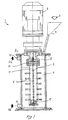
- Figure 1 illustrates schematically and in section a mill which is provided with a pin rotor
- Figure 2 illustrates a preferred embodiment of pins arranged in pairs.
- FIG. 1 is a sectional view of a mill 1 having a rotor 3 by means of which a grinding medium is agitated.
- the mill 1 includes a grinding chamber 2 in which the rotor 3 is mounted in the vertical extension of the chamber.
- the grinding chamber 2 contains a grinding medium 4 in the form of a particulate, hard material, mineral or metal alloy, having a particle size of between 0.2 and 12 mm. It is also possible to use coarser particles of the material being ground as grinding medium or bodies, in which case the process will be a so-called autogenous grinding process.
- the grinding medium 4 is introduced through a funnel 5, as indicated by the arrow 6, until there is reached in the grinding chamber 2 a level which corresponds approximately to 75-80% of the volumetric capacity of the chamber.
- the rotor 3 located in the chamber 2 is driven by a motor 7 which is mounted above the chamber 2 and which supplies power to the chamber 2 through the intermediary of a coupling arrangement 12 and a bolt joint 13, which secures the rotor 3 axially.
- the rotor 3 has a number of pins 8 disposed along its longitudinal axis. The pins 8 are arranged in pairs, partly in the section plane and partly in a plane transversal to this section plane. These latter pins 8 are therefore shown as circles in the drawing.
- the pins 8 are anchored in the rotor 3 by means of an anchoring device 11 which extends through a pin holder, not shown.
- the material to be ground is introduced through an inlet aperture 9, as indicated by the arrow 9a, and is caused to pass upwardly through the agitated medium 4 in the grinding chamber 2.
- the material may be introduced in the form of an aqueous suspension or slurry for wet grinding purposes, or in a dry form for dry grinding purposes.
- the finished ground material is removed through an outlet 10, as indicated by the arrow 10a.
- the mill 1 can operate with or without cooling. When cooling is desired, for instance when dry grinding, a coolant is delivered to a cooling jacket (not shown) said coolant being introduced to the upper part of the grinding chamber 2 and removed at or close to the bottom thereof.
- Figure 2 illustrates from one side and from above a preferred embodiment of a pin pair, generally referenced 21.
- the pin pair 21 is produced in several, mutually joined pieces and comprises cylindrical pin parts 22 and a holder 23 which joins said pin parts and which has cylindrical abutment parts 24 and an intermediate holder part, here shown to have a rectangular cross-section.
- Located centrally in the holder 23 is a circular hole 25 which is intended to receive an anchoring device, in the manner illustrated in Figure 1.
- the holder 23 may alternatively have a circular configuration although the flat rectangular configuration of the illustrated embodiment enables adjacent pin-pairs 21 to be anchored close together, therewith enabling more pin-pairs to be mounted on the rotor for each unit of rotor length.
- the inventive apparatus enables minerals to be ground to extremely fine grain sizes with a considerable saving in energy as compared with conventional grinding techniques.
- a typical figure in this respect is an energy consumption in kWh/tonne which is only 0.50-0.66 of the amount of energy consumed in a conventional grinding process.
- Another important advantage afforded by the invention is that the mills become much smaller volumetrically, therewith enabling the mills to be positioned more readily and to be made more flexible, for instance the mills can be readily placed in the proximity of those units from which the material arrives, without needing to pump the material over long distances, which requires a large energy input.
- the inventive cemented metal carbide pins had an effective life span of between 3000 and 5000 hours. This life span is expressed as the number of hours over which the pins carried out their intended function in a grinding process. Pins provided with outer, hard layers or coatings in accordance with the earlier standpoint of techniques were also tested.
- pins provided with hard metal sleeves had a much shorter effective life, less than 100 hours, due to the fact that the anchoring devices, the screws, were worn down quickly, therewith causing the sleeves to loosen and be quickly destroyed in the mill.
- Pins coated with tungsten carbide to a thickness of 0.10-0.12 mm had an effective life of between 100 and 150 hours. This result was taken to indicate that the effective life of surface hardened pins is, at best, substantially proportional to the thickness of the surface hardened casing. In several instances, however, the effective life of the pins was shorter due to local erosion and exposure of the underlying steel pins which apparently resulted in rapid immediate wear of the pins, causing the pins to break off.
Abstract
Description
- The invention relates to apparatus for grinding mineral products and similar hard materials with the aid of a medium agitated by a pin rotor, i.e a rotor equipped with pins.
- The technique of grinding or milling material with the aid of an agitated medium (Stirred Ball Milling) has been known for almost 60 years. The industrial break-through with this technique was made in 1948 in conjunction with pigment milling in the paint and laquer industries. The technique has been developed progressively over recent years and has been increasingly applied. As a result, many different types of mills in which milling is effected with an agitated medium have been proposed, as is evident, for instance, from an article in International Journal of Mineral Processing, 22 (1988), pages 431-444. One of these mills includes pin-agitator rotors by means of which the necessary milling energy is introduced by forced displacement of the grinding medium.
- Due to the ability of the mills to grind or comminute material rapidly to very fine grain sizes, normally within a range of 1-10 microns, grinding with agitated media has been utilized to progressively greater extents with various types of material. Such fine grinding processes are thus employed in the production of fine grain products within the paint and laquer industry, the pharmacological industry, the electronic industry, the agrochemical industry, the food industry, the biotechnical industry, and the rubber, coal and energy industries. Coal-oil-mixtures and coal-water-suspensions are examples of this latter use. The technique of grinding with an agitated medium is also beginning to be applied in mineral technology. For instance, the technique is applied for grinding lime-stone, kaolin, gypsum, aluminium hydroxide and in the manufacture of paper fillers and paper coating materials. It is evident from this recitation that the majority of applications within the mineral field are concerned solely with "soft" material which is milled relatively easily. One such mill is described in US-A-4 244 531 with particular reference to milling aluminium powder and cocoa powder, among other things.
- In recent time, the use of this technique has been reported in South Africa for the recovery of the precious metal content of pyrites and roasted pyrites, wherein it is found that leaching of extremely small amounts of gold and other precious metals from these products is highly enhanced with particle fineness. It is found, however, that grinding for maximum recovery requires a grinding time of 6-8 hours. EP-A-0 267 170 described the re-grinding of a return product in the processing or enrichment of mineral products, wherein the return product is re-ground with the intention of crushing individual half-grains (i.e. in principle particles which contain both ore and gangue) and with the intention of separating valuable mineral. The re-grinding process is carried out in a mill with the aid of an agitated grinding medium and the material is ground to a particle size smaller than K₈₀ = 100 microns. According to the publication, re-grinding is effected with a limited energy input.
- The results of the research carried out in recent years show that the fineness of the ground material achieved when grinding with agitated grinding media is contingent solely on the specific energy supply, which can be expressed kwh/tonne of ground material. The results also show that the advantages afforded by this grinding technique over alternative techniques are greatly enhanced with increased fineness of the ground material, i.e. grinding with an agitated grinding medium becomes progressively more attractive with the fineness desired of the final product. Thus, a finer end product requires a higher specific energy input, i.e. a higher specific power input and/or longer grinding time. Obviously, an attempt to achieve greater fineness is initially made with a higher power input, so as not to negatively influence the productivity of the mills. Grinding times of 6-8 hours, as mentioned for instance in connection with pyrite grinding in South Africa, is naturally not as attractive, although in many cases necessary since an increase in power input would place unduly large demands on the ability of the mill to withstand a hard wearing environment, particularly when grinding such hard materials as ores. It has been found that the pin rotor of the mills is primarily subjected to wear much more quickly when the power input is increased. These pins normally consist of non-alloyed steel, although there have been tested steel pins provided with an external hard metal coating with the intention of increasing wear resistance. This hard metal protective coating may also have the form of a sleeve fitted onto the pin and screwed firmly thereto, or in the form of a surface hardened coating applied directly to the steel surface, as proposed in GB-A-1 197 582 for instance.
- Hitherto, efforts to increase the power in mills which use pin rotors have failed because of the excessively rapid wear of the pins or because the pins loosen from the rotor, this drawback presenting a serious obstacle which in practice makes it impossible to use this technique for the purpose of processing ores.
- There is a progressively increasing need for enabling the power input to be increased when grinding progressively harder materials, for the purpose of producing a progressively finer grinding product when grinding with a grinding medium which is agitated by a pin rotor.
- One object of the present invention is to provide apparatus which will enable the aforedescribed grinding technique to be applied effectively in ore processing operations.
- This object is achieved by the inventive apparatus having the characteristic features set forth in the accompanying claims.
- Thus, it is surprisingly found that mills in which a grinding medium is agitated with a pin rotor are able to withstand higher power inputs and harder input material under substantially longer operating times without needing to stop for repairs when the rotor pins are made of cemented metal carbide. The pins are preferably detachable from the rotor, or may also be detachably anchored to the rotor, which is normally made of an alloyed steel, for instance a chromiumnickel-steel. It has been found particularly advantageous when two pins form a pin pair with the aid of a holder which is anchored throughout in the rotor. This preferred embodiment provides a simpler technique for anchoring the pins in the rotor, and also reduces the risk of a pin loosening from its anchorage. In the case of this preferred embodiment comprising pairs of pins, the pin-pairs are preferably anchored in said holder with the aid of devices which extend into the rotor, essentially in the longitudinal extension thereof. The anchoring devices may, for instance, have the form of rods or tubes of cylindrical profile or some other profile.
- The holder part of the pin pairs located inside the rotor may be substantially flat, in order to enable the pins-pairs to be positioned close together on the rotor in the direction of the longitudinal axis thereof. The pins are preferably anchored in the rotor diametrically in different directions along the rotor and preferably so that two or more pins or pins-pairs are anchored at substantially the same distance from the ends of the rotor.
- The pins are suitably configured so that those parts of the pins which are not anchored in the rotor will have a substantially circular cross-section. In normal cases, the cross-sectional diameter of the circular pins will be within the range of 20-50 mm, preferably about 30 mm.
- The invention will now be described in more detail with reference to the accompanying Figures, in which Figure 1 illustrates schematically and in section a mill which is provided with a pin rotor, and Figure 2 illustrates a preferred embodiment of pins arranged in pairs.
- Figure 1 is a sectional view of a mill 1 having a rotor 3 by means of which a grinding medium is agitated. The mill 1 includes a
grinding chamber 2 in which the rotor 3 is mounted in the vertical extension of the chamber. Thegrinding chamber 2 contains agrinding medium 4 in the form of a particulate, hard material, mineral or metal alloy, having a particle size of between 0.2 and 12 mm. It is also possible to use coarser particles of the material being ground as grinding medium or bodies, in which case the process will be a so-called autogenous grinding process. Thegrinding medium 4 is introduced through afunnel 5, as indicated by the arrow 6, until there is reached in the grinding chamber 2 a level which corresponds approximately to 75-80% of the volumetric capacity of the chamber. The rotor 3 located in thechamber 2 is driven by amotor 7 which is mounted above thechamber 2 and which supplies power to thechamber 2 through the intermediary of a coupling arrangement 12 and abolt joint 13, which secures the rotor 3 axially. The rotor 3 has a number ofpins 8 disposed along its longitudinal axis. Thepins 8 are arranged in pairs, partly in the section plane and partly in a plane transversal to this section plane. Theselatter pins 8 are therefore shown as circles in the drawing. - The
pins 8 are anchored in the rotor 3 by means of ananchoring device 11 which extends through a pin holder, not shown. - The material to be ground is introduced through an inlet aperture 9, as indicated by the arrow 9a, and is caused to pass upwardly through the
agitated medium 4 in thegrinding chamber 2. The material may be introduced in the form of an aqueous suspension or slurry for wet grinding purposes, or in a dry form for dry grinding purposes. The finished ground material is removed through anoutlet 10, as indicated by the arrow 10a. The mill 1 can operate with or without cooling. When cooling is desired, for instance when dry grinding, a coolant is delivered to a cooling jacket (not shown) said coolant being introduced to the upper part of thegrinding chamber 2 and removed at or close to the bottom thereof. - Figure 2 illustrates from one side and from above a preferred embodiment of a pin pair, generally referenced 21.
- The
pin pair 21 is produced in several, mutually joined pieces and comprisescylindrical pin parts 22 and aholder 23 which joins said pin parts and which hascylindrical abutment parts 24 and an intermediate holder part, here shown to have a rectangular cross-section. Located centrally in theholder 23 is acircular hole 25 which is intended to receive an anchoring device, in the manner illustrated in Figure 1. Theholder 23 may alternatively have a circular configuration although the flat rectangular configuration of the illustrated embodiment enables adjacent pin-pairs 21 to be anchored close together, therewith enabling more pin-pairs to be mounted on the rotor for each unit of rotor length. - The inventive apparatus enables minerals to be ground to extremely fine grain sizes with a considerable saving in energy as compared with conventional grinding techniques. A typical figure in this respect is an energy consumption in kWh/tonne which is only 0.50-0.66 of the amount of energy consumed in a conventional grinding process. Another important advantage afforded by the invention is that the mills become much smaller volumetrically, therewith enabling the mills to be positioned more readily and to be made more flexible, for instance the mills can be readily placed in the proximity of those units from which the material arrives, without needing to pump the material over long distances, which requires a large energy input.
- When carrying out tests for grinding minerals down to grain sizes smaller than 0.1 mm, it was found that the inventive cemented metal carbide pins had an effective life span of between 3000 and 5000 hours. This life span is expressed as the number of hours over which the pins carried out their intended function in a grinding process. Pins provided with outer, hard layers or coatings in accordance with the earlier standpoint of techniques were also tested.
- Thus, pins provided with hard metal sleeves had a much shorter effective life, less than 100 hours, due to the fact that the anchoring devices, the screws, were worn down quickly, therewith causing the sleeves to loosen and be quickly destroyed in the mill. Pins coated with tungsten carbide to a thickness of 0.10-0.12 mm had an effective life of between 100 and 150 hours. This result was taken to indicate that the effective life of surface hardened pins is, at best, substantially proportional to the thickness of the surface hardened casing. In several instances, however, the effective life of the pins was shorter due to local erosion and exposure of the underlying steel pins which apparently resulted in rapid immediate wear of the pins, causing the pins to break off.
Claims (8)
- Apparatus for grinding mineral products and similar hard materials with the aid of a grinding medium (4) agitated by a pin rotor (3), characterized in that the pins (8) of the rotor (3) are made of cemented metal carbide.
- Apparatus according to Claim 1, characterized in that the pins (8) are detachably anchored in the rotor (3).
- Apparatus according to Claim 1 or 2, characterized in that two pins (8, 22) form a pin-pair (21) with the aid of a holder (23) which is anchored in the rotor (3) throughout.
- Apparatus according to Claim 3, characterized in that the pin-pairs (21) are anchored in the rotor (3) with the aid of devices (11) which extend into the rotor (3), substantially in its longitudinal direction.
- Apparatus according to Claim 3 or 4, characterized in that the pin-pair holder (23) located in the rotor (3) is substantially flat.
- Apparatus according to any one of Claims 1-5, characterized in that the pins (8, 22) are anchored diametrically in different directions along the rotor (3).
- Apparatus according to Claim 6, characterized in that two or more pins (8) or pin-pairs (21) are anchored at substantially the same distance from the ends of the rotor (3).
- Apparatus according Claims 1-7, characterized in that the part of the pins (8, 22) not anchored in the rotor (3) has a substantially circular cross-section.
Applications Claiming Priority (2)
| Application Number | Priority Date | Filing Date | Title |
|---|---|---|---|
| SE9000797A SE9000797L (en) | 1990-03-07 | 1990-03-07 | DEVICE FOR MILLING OF MINERAL PRODUCTS |
| SE9000797 | 1990-03-07 |
Publications (2)
| Publication Number | Publication Date |
|---|---|
| EP0451121A1 true EP0451121A1 (en) | 1991-10-09 |
| EP0451121B1 EP0451121B1 (en) | 1994-08-31 |
Family
ID=20378782
Family Applications (1)
| Application Number | Title | Priority Date | Filing Date |
|---|---|---|---|
| EP91850053A Expired - Lifetime EP0451121B1 (en) | 1990-03-07 | 1991-03-05 | An apparatus for grinding mineral products |
Country Status (10)
| Country | Link |
|---|---|
| US (1) | US5133506A (en) |
| EP (1) | EP0451121B1 (en) |
| AT (1) | ATE110590T1 (en) |
| AU (1) | AU628716B2 (en) |
| CA (1) | CA2037196C (en) |
| DE (1) | DE69103662T2 (en) |
| DK (1) | DK0451121T3 (en) |
| ES (1) | ES2063486T3 (en) |
| SE (1) | SE9000797L (en) |
| ZA (1) | ZA911208B (en) |
Cited By (3)
| Publication number | Priority date | Publication date | Assignee | Title |
|---|---|---|---|---|
| EP0665060A1 (en) * | 1994-01-26 | 1995-08-02 | Sala International AB | An arrangement for milling mineral products |
| WO1998001225A1 (en) * | 1996-07-04 | 1998-01-15 | Lidstroem Lars | A grinding method and apparatus therefor |
| CN106391197A (en) * | 2016-10-09 | 2017-02-15 | 芜湖瑞德机械科技有限公司 | Homogenizing device for putty powder for building decoration and operation method of homogenizing device |
Families Citing this family (8)
| Publication number | Priority date | Publication date | Assignee | Title |
|---|---|---|---|---|
| SE466485B (en) * | 1991-03-25 | 1992-02-24 | Sala International Ab | PROCEDURE FOR MILLING OF FOOD FILLER DAMA USING MATERIAL IN SUBSTANTALLY DRY CONDITION UNDER APPLICATION OF A MILLED MEDIUM MILLED MEDIUM AND DEVICE FOR IMPLEMENTATION OF THE PROCEDURE |
| SE469417B (en) * | 1991-12-20 | 1993-07-05 | Sala International Ab | SETTING AND DEVICE FOR FINAL PAINTING OF FOOD FILLER DAMAGES APPLICABLE MINERALS IN DRY CONDITION |
| US5433899A (en) * | 1992-08-17 | 1995-07-18 | Trw Vehicle Safety Systems Inc. | Process of manufacturing a gas generating material |
| ATE271922T1 (en) | 1999-06-01 | 2004-08-15 | Elan Pharma Int Ltd | SMALL MILL AND METHOD THEREOF |
| US6264039B1 (en) | 1999-10-21 | 2001-07-24 | The University Of Akron | Method for precious metal recovery from slag |
| US7731111B2 (en) * | 2006-04-13 | 2010-06-08 | Mill Creek Enterprises, Inc. | Apparatus and method for processing vegetative material |
| CN104226427B (en) * | 2014-08-15 | 2017-03-29 | 广东派勒智能纳米科技股份有限公司 | The big flow pin-connected panel lapping device of nanometer sand mill |
| CN105032563B (en) * | 2015-07-13 | 2018-07-17 | 内蒙古超牌建材科技有限公司 | Vertical wet-process ball mill |
Citations (3)
| Publication number | Priority date | Publication date | Assignee | Title |
|---|---|---|---|---|
| GB1197582A (en) * | 1967-03-23 | 1970-07-08 | Andrew Szegvari | Grinding and Dispersing Apparatus |
| SE401618B (en) * | 1972-09-21 | 1978-05-22 | Ver Edelstahlwerke Ag | BATTLE LIST FOR BATTLES |
| US4244531A (en) * | 1978-10-31 | 1981-01-13 | Union Process, Inc. | Agitated-media mill with a baffled inner wall |
Family Cites Families (7)
| Publication number | Priority date | Publication date | Assignee | Title |
|---|---|---|---|---|
| US3149789A (en) * | 1960-10-28 | 1964-09-22 | Szegvari Andrew | Continuous process of grinding particulate material |
| DE1607476A1 (en) * | 1967-10-10 | 1969-09-18 | Draiswerke Gmbh | Continuously operated agitator mill |
| DE1757953C3 (en) * | 1968-07-01 | 1979-09-27 | Veb Maschinenfabrik Heidenau, Ddr 8312 Heidenau | Agitator mill |
| DE3440993A1 (en) * | 1984-11-09 | 1986-05-22 | Omya GmbH, 5000 Köln | AGITATOR MILL, ESPECIALLY AGITATOR BALL MILL |
| SE8604241D0 (en) * | 1986-10-06 | 1986-10-06 | Lars Jorgen Lidstrom | RETURN MATERIALS PROCESSING |
| US4850541A (en) * | 1987-08-24 | 1989-07-25 | Hagy John T | Comminution apparatus |
| US4979686A (en) * | 1989-10-03 | 1990-12-25 | Union Process, Inc. | High speed dry grinder |
-
1990
- 1990-03-07 SE SE9000797A patent/SE9000797L/en not_active Application Discontinuation
-
1991
- 1991-02-12 AU AU70984/91A patent/AU628716B2/en not_active Ceased
- 1991-02-19 ZA ZA911208A patent/ZA911208B/en unknown
- 1991-02-27 CA CA002037196A patent/CA2037196C/en not_active Expired - Fee Related
- 1991-02-28 US US07/662,228 patent/US5133506A/en not_active Expired - Fee Related
- 1991-03-05 ES ES91850053T patent/ES2063486T3/en not_active Expired - Lifetime
- 1991-03-05 EP EP91850053A patent/EP0451121B1/en not_active Expired - Lifetime
- 1991-03-05 DE DE69103662T patent/DE69103662T2/en not_active Expired - Fee Related
- 1991-03-05 DK DK91850053.9T patent/DK0451121T3/en active
- 1991-03-05 AT AT91850053T patent/ATE110590T1/en not_active IP Right Cessation
Patent Citations (3)
| Publication number | Priority date | Publication date | Assignee | Title |
|---|---|---|---|---|
| GB1197582A (en) * | 1967-03-23 | 1970-07-08 | Andrew Szegvari | Grinding and Dispersing Apparatus |
| SE401618B (en) * | 1972-09-21 | 1978-05-22 | Ver Edelstahlwerke Ag | BATTLE LIST FOR BATTLES |
| US4244531A (en) * | 1978-10-31 | 1981-01-13 | Union Process, Inc. | Agitated-media mill with a baffled inner wall |
Cited By (3)
| Publication number | Priority date | Publication date | Assignee | Title |
|---|---|---|---|---|
| EP0665060A1 (en) * | 1994-01-26 | 1995-08-02 | Sala International AB | An arrangement for milling mineral products |
| WO1998001225A1 (en) * | 1996-07-04 | 1998-01-15 | Lidstroem Lars | A grinding method and apparatus therefor |
| CN106391197A (en) * | 2016-10-09 | 2017-02-15 | 芜湖瑞德机械科技有限公司 | Homogenizing device for putty powder for building decoration and operation method of homogenizing device |
Also Published As
| Publication number | Publication date |
|---|---|
| DE69103662T2 (en) | 1994-12-22 |
| ATE110590T1 (en) | 1994-09-15 |
| ES2063486T3 (en) | 1995-01-01 |
| EP0451121B1 (en) | 1994-08-31 |
| AU7098491A (en) | 1991-09-26 |
| ZA911208B (en) | 1991-11-27 |
| SE9000797D0 (en) | 1990-03-07 |
| CA2037196A1 (en) | 1991-09-08 |
| DE69103662D1 (en) | 1994-10-06 |
| DK0451121T3 (en) | 1994-10-31 |
| SE9000797L (en) | 1991-09-08 |
| US5133506A (en) | 1992-07-28 |
| CA2037196C (en) | 1996-09-03 |
| AU628716B2 (en) | 1992-09-17 |
Similar Documents
| Publication | Publication Date | Title |
|---|---|---|
| EP0451121B1 (en) | An apparatus for grinding mineral products | |
| Shi et al. | Comparison of energy efficiency between ball mills and stirred mills in coarse grinding | |
| Orumwense et al. | Superfine and ultrafine grinding—a literature survey | |
| CN101282790B (en) | Method for increasing efficiency of grinding of ores, minerals and concentrates | |
| CA2081177C (en) | Beneficiation process | |
| Stehr | Recent developments in stirred ball milling | |
| Gao et al. | IsaMill fine grinding technology and its industrial applications at Mount Isa Mines | |
| EP1078107B1 (en) | Ore comminution process using bed-compression method at low pressures and installation therefor | |
| US20190329262A1 (en) | Rock Mill Lifter | |
| JPH09150072A (en) | Manufacture of slurry and device therefor | |
| CN108452875B (en) | A kind of high accuracy circular conic crusher | |
| AU681201B2 (en) | An arrangement for milling mineral products | |
| Clarke et al. | Technical note Enhancement of cassiterite liberation by high pressure roller comminution | |
| US6436523B1 (en) | Delaminated sedimentary mica | |
| US5333798A (en) | Method and system for pounding brittle material | |
| Lofthouse et al. | The Svedala (ECC International) detritor and the metals industry | |
| Jankovic et al. | Fine grinding in the Australian mining industry | |
| Orumwense | Effect of media type on regrinding with stirred mills | |
| US6032882A (en) | Method for circulation grinding of brittle grinding stock and grinding apparatus therefor | |
| Fuerstenau et al. | A new approach to assessing the grindability of solids and the energy efficiency of grinding mills | |
| CN2249636Y (en) | Fine wet mill with bar-plate agitater | |
| US3162379A (en) | Method for delaminating sized laminar mineral particles | |
| KR20020044622A (en) | Producing Process for Industrial Fillers from Sericitic Pottery-stone | |
| Balasubramanian | Size Reduction by grinding methods | |
| Johnson | Review of existing eco-efficient comminution devices |
Legal Events
| Date | Code | Title | Description |
|---|---|---|---|
| PUAI | Public reference made under article 153(3) epc to a published international application that has entered the european phase |
Free format text: ORIGINAL CODE: 0009012 |
|
| AK | Designated contracting states |
Kind code of ref document: A1 Designated state(s): AT BE CH DE DK ES FR GB GR IT LI NL SE |
|
| 17P | Request for examination filed |
Effective date: 19920330 |
|
| 17Q | First examination report despatched |
Effective date: 19930616 |
|
| GRAA | (expected) grant |
Free format text: ORIGINAL CODE: 0009210 |
|
| AK | Designated contracting states |
Kind code of ref document: B1 Designated state(s): AT BE CH DE DK ES FR GB GR IT LI NL SE |
|
| PG25 | Lapsed in a contracting state [announced via postgrant information from national office to epo] |
Ref country code: NL Effective date: 19940831 Ref country code: LI Effective date: 19940831 Ref country code: GR Free format text: LAPSE BECAUSE OF FAILURE TO SUBMIT A TRANSLATION OF THE DESCRIPTION OR TO PAY THE FEE WITHIN THE PRESCRIBED TIME-LIMIT Effective date: 19940831 Ref country code: CH Effective date: 19940831 Ref country code: BE Effective date: 19940831 Ref country code: AT Effective date: 19940831 |
|
| REF | Corresponds to: |
Ref document number: 110590 Country of ref document: AT Date of ref document: 19940915 Kind code of ref document: T |
|
| REF | Corresponds to: |
Ref document number: 69103662 Country of ref document: DE Date of ref document: 19941006 |
|
| REG | Reference to a national code |
Ref country code: DK Ref legal event code: T3 |
|
| ET | Fr: translation filed | ||
| ITF | It: translation for a ep patent filed |
Owner name: UFFICIO BREVETTI RICCARDI & C. |
|
| REG | Reference to a national code |
Ref country code: CH Ref legal event code: PL |
|
| REG | Reference to a national code |
Ref country code: ES Ref legal event code: FG2A Ref document number: 2063486 Country of ref document: ES Kind code of ref document: T3 |
|
| EAL | Se: european patent in force in sweden |
Ref document number: 91850053.9 |
|
| NLV1 | Nl: lapsed or annulled due to failure to fulfill the requirements of art. 29p and 29m of the patents act | ||
| PLBI | Opposition filed |
Free format text: ORIGINAL CODE: 0009260 |
|
| 26 | Opposition filed |
Opponent name: OMYA GMBH Effective date: 19950530 |
|
| APAC | Appeal dossier modified |
Free format text: ORIGINAL CODE: EPIDOS NOAPO |
|
| APAA | Appeal reference recorded |
Free format text: ORIGINAL CODE: EPIDOS REFN |
|
| APCC | Communication from the board of appeal sent |
Free format text: ORIGINAL CODE: EPIDOS OBAPO |
|
| APCC | Communication from the board of appeal sent |
Free format text: ORIGINAL CODE: EPIDOS OBAPO |
|
| APAC | Appeal dossier modified |
Free format text: ORIGINAL CODE: EPIDOS NOAPO |
|
| PLBO | Opposition rejected |
Free format text: ORIGINAL CODE: EPIDOS REJO |
|
| PLBN | Opposition rejected |
Free format text: ORIGINAL CODE: 0009273 |
|
| STAA | Information on the status of an ep patent application or granted ep patent |
Free format text: STATUS: OPPOSITION REJECTED |
|
| 27O | Opposition rejected |
Effective date: 19971017 |
|
| PGFP | Annual fee paid to national office [announced via postgrant information from national office to epo] |
Ref country code: DE Payment date: 19991231 Year of fee payment: 10 |
|
| PGFP | Annual fee paid to national office [announced via postgrant information from national office to epo] |
Ref country code: GB Payment date: 20000301 Year of fee payment: 10 |
|
| PGFP | Annual fee paid to national office [announced via postgrant information from national office to epo] |
Ref country code: SE Payment date: 20000307 Year of fee payment: 10 |
|
| PGFP | Annual fee paid to national office [announced via postgrant information from national office to epo] |
Ref country code: FR Payment date: 20000310 Year of fee payment: 10 |
|
| PGFP | Annual fee paid to national office [announced via postgrant information from national office to epo] |
Ref country code: DK Payment date: 20000313 Year of fee payment: 10 |
|
| PGFP | Annual fee paid to national office [announced via postgrant information from national office to epo] |
Ref country code: ES Payment date: 20000322 Year of fee payment: 10 |
|
| PG25 | Lapsed in a contracting state [announced via postgrant information from national office to epo] |
Ref country code: GB Free format text: LAPSE BECAUSE OF NON-PAYMENT OF DUE FEES Effective date: 20010305 Ref country code: DK Free format text: LAPSE BECAUSE OF NON-PAYMENT OF DUE FEES Effective date: 20010305 |
|
| PG25 | Lapsed in a contracting state [announced via postgrant information from national office to epo] |
Ref country code: SE Free format text: LAPSE BECAUSE OF NON-PAYMENT OF DUE FEES Effective date: 20010306 Ref country code: ES Free format text: LAPSE BECAUSE OF NON-PAYMENT OF DUE FEES Effective date: 20010306 |
|
| GBPC | Gb: european patent ceased through non-payment of renewal fee |
Effective date: 20010305 |
|
| EUG | Se: european patent has lapsed |
Ref document number: 91850053.9 |
|
| PG25 | Lapsed in a contracting state [announced via postgrant information from national office to epo] |
Ref country code: FR Free format text: LAPSE BECAUSE OF NON-PAYMENT OF DUE FEES Effective date: 20011130 |
|
| REG | Reference to a national code |
Ref country code: DK Ref legal event code: EBP |
|
| REG | Reference to a national code |
Ref country code: FR Ref legal event code: ST |
|
| PG25 | Lapsed in a contracting state [announced via postgrant information from national office to epo] |
Ref country code: DE Free format text: LAPSE BECAUSE OF NON-PAYMENT OF DUE FEES Effective date: 20020101 |
|
| REG | Reference to a national code |
Ref country code: ES Ref legal event code: FD2A Effective date: 20030203 |
|
| PG25 | Lapsed in a contracting state [announced via postgrant information from national office to epo] |
Ref country code: IT Free format text: LAPSE BECAUSE OF NON-PAYMENT OF DUE FEES;WARNING: LAPSES OF ITALIAN PATENTS WITH EFFECTIVE DATE BEFORE 2007 MAY HAVE OCCURRED AT ANY TIME BEFORE 2007. THE CORRECT EFFECTIVE DATE MAY BE DIFFERENT FROM THE ONE RECORDED. Effective date: 20050305 |
|
| APAH | Appeal reference modified |
Free format text: ORIGINAL CODE: EPIDOSCREFNO |