EP0450861B1 - Process for hydrocarbon synthesis using slurry Fischer-Tropsch process with Co/TiO2 catalyst - Google Patents
Process for hydrocarbon synthesis using slurry Fischer-Tropsch process with Co/TiO2 catalyst Download PDFInfo
- Publication number
- EP0450861B1 EP0450861B1 EP91302711A EP91302711A EP0450861B1 EP 0450861 B1 EP0450861 B1 EP 0450861B1 EP 91302711 A EP91302711 A EP 91302711A EP 91302711 A EP91302711 A EP 91302711A EP 0450861 B1 EP0450861 B1 EP 0450861B1
- Authority
- EP
- European Patent Office
- Prior art keywords
- cobalt
- catalyst
- reactor
- titania
- productivity
- Prior art date
- Legal status (The legal status is an assumption and is not a legal conclusion. Google has not performed a legal analysis and makes no representation as to the accuracy of the status listed.)
- Expired - Lifetime
Links
Images

Classifications
-
- C—CHEMISTRY; METALLURGY
- C07—ORGANIC CHEMISTRY
- C07C—ACYCLIC OR CARBOCYCLIC COMPOUNDS
- C07C1/00—Preparation of hydrocarbons from one or more compounds, none of them being a hydrocarbon
- C07C1/02—Preparation of hydrocarbons from one or more compounds, none of them being a hydrocarbon from oxides of a carbon
- C07C1/04—Preparation of hydrocarbons from one or more compounds, none of them being a hydrocarbon from oxides of a carbon from carbon monoxide with hydrogen
- C07C1/0455—Reaction conditions
- C07C1/046—Numerical values of parameters
-
- C—CHEMISTRY; METALLURGY
- C07—ORGANIC CHEMISTRY
- C07C—ACYCLIC OR CARBOCYCLIC COMPOUNDS
- C07C1/00—Preparation of hydrocarbons from one or more compounds, none of them being a hydrocarbon
- C07C1/02—Preparation of hydrocarbons from one or more compounds, none of them being a hydrocarbon from oxides of a carbon
- C07C1/04—Preparation of hydrocarbons from one or more compounds, none of them being a hydrocarbon from oxides of a carbon from carbon monoxide with hydrogen
- C07C1/06—Preparation of hydrocarbons from one or more compounds, none of them being a hydrocarbon from oxides of a carbon from carbon monoxide with hydrogen in the presence of organic compounds, e.g. hydrocarbons
- C07C1/063—Preparation of hydrocarbons from one or more compounds, none of them being a hydrocarbon from oxides of a carbon from carbon monoxide with hydrogen in the presence of organic compounds, e.g. hydrocarbons the organic compound being the catalyst or a part of the catalyst system
- C07C1/066—Preparation of hydrocarbons from one or more compounds, none of them being a hydrocarbon from oxides of a carbon from carbon monoxide with hydrogen in the presence of organic compounds, e.g. hydrocarbons the organic compound being the catalyst or a part of the catalyst system used for dissolving, suspending or transporting the catalyst
-
- C—CHEMISTRY; METALLURGY
- C07—ORGANIC CHEMISTRY
- C07C—ACYCLIC OR CARBOCYCLIC COMPOUNDS
- C07C2521/00—Catalysts comprising the elements, oxides or hydroxides of magnesium, boron, aluminium, carbon, silicon, titanium, zirconium or hafnium
- C07C2521/06—Silicon, titanium, zirconium or hafnium; Oxides or hydroxides thereof
-
- C—CHEMISTRY; METALLURGY
- C07—ORGANIC CHEMISTRY
- C07C—ACYCLIC OR CARBOCYCLIC COMPOUNDS
- C07C2523/00—Catalysts comprising metals or metal oxides or hydroxides, not provided for in group C07C2521/00
- C07C2523/16—Catalysts comprising metals or metal oxides or hydroxides, not provided for in group C07C2521/00 of arsenic, antimony, bismuth, vanadium, niobium, tantalum, polonium, chromium, molybdenum, tungsten, manganese, technetium or rhenium
- C07C2523/32—Manganese, technetium or rhenium
- C07C2523/36—Rhenium
-
- C—CHEMISTRY; METALLURGY
- C07—ORGANIC CHEMISTRY
- C07C—ACYCLIC OR CARBOCYCLIC COMPOUNDS
- C07C2523/00—Catalysts comprising metals or metal oxides or hydroxides, not provided for in group C07C2521/00
- C07C2523/70—Catalysts comprising metals or metal oxides or hydroxides, not provided for in group C07C2521/00 of the iron group metals or copper
- C07C2523/74—Iron group metals
- C07C2523/75—Cobalt
-
- C—CHEMISTRY; METALLURGY
- C07—ORGANIC CHEMISTRY
- C07C—ACYCLIC OR CARBOCYCLIC COMPOUNDS
- C07C2523/00—Catalysts comprising metals or metal oxides or hydroxides, not provided for in group C07C2521/00
- C07C2523/70—Catalysts comprising metals or metal oxides or hydroxides, not provided for in group C07C2521/00 of the iron group metals or copper
- C07C2523/76—Catalysts comprising metals or metal oxides or hydroxides, not provided for in group C07C2521/00 of the iron group metals or copper combined with metals, oxides or hydroxides provided for in groups C07C2523/02 - C07C2523/36
- C07C2523/84—Catalysts comprising metals or metal oxides or hydroxides, not provided for in group C07C2521/00 of the iron group metals or copper combined with metals, oxides or hydroxides provided for in groups C07C2523/02 - C07C2523/36 with arsenic, antimony, bismuth, vanadium, niobium, tantalum, polonium, chromium, molybdenum, tungsten, manganese, technetium or rhenium
- C07C2523/889—Manganese, technetium or rhenium
Definitions
- This invention relates to a hydrocarbon synthesis process.
- the hydrocarbon synthesis process involves the catalytic hydrogenation of carbon monoxide with hydrogen to form higher hydrocarbons, preferably C5+ hydrocarbons. Hydrogen and carbon monoxide, synthesis gas, are contacted with a suitable catalyst at appropriate reaction conditions, usually elevated temperatures and pressures, to produce the desired hydrocarbons.
- Catalytic materials usually include Group VIII metals, particularly iron, cobalt, ruthenium, and nickel supported on a porous inorganic oxide support, such as the oxides of Group IIIA, IV, VA.
- Promoter materials can be employed, e.g., rhenium, hafnium and other lanthanide metals, zirconium and other Group VIII metals, as well as the metals of Groups IA, IB and IIA.
- the results obtained with a particular catalyst may vary considerably from results obtained from any other catalyst system.
- the type of reaction system in which the catalyst is placed can affect the results.
- the two extremes or poles of reaction system are the plug flow system, exemplified by a fixed catalyst bed where back mixing is either non-existent or considerably minimized, and the well stirred system where complete back mixing is effected, exemplified by fluidized beds and in liquid phase systems by the well stirred or fully back mixed reactor system.
- the rate of CO conversion and product selectivity depends on the partial pressure of the reactants, hydrogen and carbon monoxide, and in some cases the products, e.g., water, olefins, in contact with the catalyst.
- the mixing characteristics of the reactor become critical in determining catalyst performance since these characteristics will determine the gas phase composition (and therefore, the partial pressure of the reactants) at any particular point in the reactor.
- the composition of reactants (gaseous) and products (liquids and gases) and condition of the catalyst at any one point in the reactor is the same as that at any other point in the reactor. Achieving this ideal state of mixing can be accomplished with mechanical stirring devices.
- the reactant concentration or gas partial pressure of hydrogen and carbon monoxide govern catalyst performance by providing the driving force of the reaction and sets the carbon monoxide conversion occurring in the reactor.
- catalyst performance is driven by the reactant gas phase concentration corresponding to the reactant gas phase concentration exiting the reactor.
- the other extreme of reactor mixing occurs in the plug flow reactor where the catalyst is stationary or relatively stationary relative to the flow of reactants (gaseous) and products (liquids and gases).
- the synthesis gas feed undergoes reaction as it enters the reactor and the reaction continues as the unreacted synthesis gas proceeds through the reactor.
- the concentration of, and partial pressure of hydrogen and carbon monoxide decreases along the path of the reactor and, therefore, the driving force of the reaction also decreases as the concentration of liquid and gaseous hydrocarbon products as well as H2O by-product increases.
- the catalyst at the exit portion of the plug flow reactor never sees fresh feed.
- the plug flow system provides maximum productivity at the expense of selectivity.
- the important difference between the fully backed mixed (CSTR) and plug flow systems is the difference in the gas phase reactant concentration that provides the kinetic driving force for the reaction.
- the reactant concentration is the same at any point in the reactor; in the plug flow system the reactant concentration steadily decreases along the path of the catalyst bed from inlet to outlet and the reaction rate is obtained by integrating the rate function from inlet to outlet.
- Reactor systems exhibiting plug flow and well stirred characteristics are the extremes of reactor performance.
- plug flow reactors may exhibit some back mixed traits and back mixed reactors may exhibit some plug flow traits. Deviations from the ideal systems are due to the dispersion of the reactant gases in the reactor. Insuring complete back mixing is a function of the mechanical energy imparted to the system.
- Reactor geometry can affect back mixing and low length to diameter ratios, less than about 3, promote back mixing in plug flow reactors. However, with higher energy inputs reactors with greater length to diameter ratios can achieve complete back mixing, too. Conversely, plug flow is favored by high length to diameter ratios.
- the degree of non-ideal back mixing that can occur in a plug flow reactor can be represented by the Peclet Number, N pe which is equal to LU/ ⁇ , where L is the reactor length (or catalyst size), U is the gas velocity, and ⁇ is the dispersion coefficient.* * Dispersion coefficient is described by Kobel and Ralek in "The Fischer-Tropsch Synthesis in the Liquid Phase", Catal.Rev.Sci.Eng., 21(2), 225-274 (1980).
- plug flow and CSTR represent the ideal extremes of reactor systems
- classical chemical engineering principles define a continuous function between plug flow and CSTR. That is, as a system is less and less ideal plug flow it will move in a continuous fashion towards CSTR; similarly, a system exhibiting less and less back mixing will move in a continuous fashion towards plug flow. Therefore, in accordance with classical chemical engineering principles, a given reactor system must follow the continuous function between ideal plug flow and ideal CSTR and cannot fall outside this function.
- productivity reactor with decreasing plug flow characteristics can be no higher than the productivity in the starting point plug flow reactor.
- the selectivity in a reactor with decreasing back mixed characteristics can be no greater than the starting point back mixed reactor.
- Patent #4,619,910 Fujimoto, Faud Kajaka, M, Bull. Chem. Soc. Jpn. 60 2237 (1987); Satterfield, C.N. et al Ind. Eng. Chem. Fund. 1985 , 24, 450-454; Dry, M.E. Catalysis Sci & Tech., Vol 1, ed. J.R. Anderson & M. Boudart, Springer Verlag (1981); Van Vuuren, Council for Scientific & Ind. Res. Rep; LENG 432 (1982).
- US-A-4 279 830 discloses carrying out a Fisher-Tropsch synthesis gas conversion in a liquid phase bubble column reactor with suspended catalyst particles. No details are given of the nature of the reactor.
- the catalyst particles employed are iron with or without an alkali metal promoter.
- EP-A-220 343 an earlier document of the present Applicants, discloses a catalyst suitable for synthesis gas conversion comprising cobalt, or cobalt/rhenium, on a titania support. Syngas conversion employs the catalyst in powdered form in fixed beds.
- a hydrocarbon synthesis process comprising reacting hydrogen and carbon monoxide, in the presence of catalyst containing cobalt on a titania support or a titania-containing support, in a slurry bubble column with the Peclet number being at least 3 but not greater than 10.
- This invention provides a process wherein catalyst stability is virtually constant (i.e., there is little if any catalyst deactivation with time), CH4 selectivity is quite low, while at the same time CO productivity is quite high, and CO2 selectivity is low.
- CO productivity is the moles CO converted per gram of catalyst - hour
- CO2 selectivity is the moles CO2 produced per 100 moles CO converted
- CH4 selectivity is the moles CH4 produced per 100 moles CO converted
- C5+ selectivity is the moles C5+ produced per 100 moles CO converted
- Catalyst stability is the percent loss in CO productivity per day.
- the invention provides a hydrocarbon synthesis system that allows the productivity of fixed bed reactors and the selectivity of back mixed reactors.
- the invention requires the combination of a cobalt/titania catalyst system and a defined bubble column reactor.
- a bubble column reactor is a slurry system: it operates in the liquid phase, but it is not a well stirred reactor. Therefore, the results, according to engineering principles should show lower productivity than a fixed bed and selectivity approaching that of a well stirred reactor.
- the defined bubble column in combination with with a cobalt/titania reactor system shows essentially at least the productivity of fixed bed reactors and the selectivity of well stirred reactors.
- the catalyst is slurried in a liquid medium, preferably the indigenous hydrocarbon wax produced by the hydrocarbon synthesis process, and the reaction takes place in a bubble column that is not a well stirred reactor, that is, N pe is greater than 3 but less than 10.
- the catalyst is promoted with rhenium.
- the slurry liquid comprises hydrocarbon synthesis waxes boiling, at atmospheric pressure, above about 700°F (371°C), more preferably between 700°F and 1025°F (371 to 551°C).
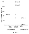
- Figure 1 shows the relationship between relative CO productivity and increasing degree of back mixing, that is from 0% back mixing in a plug flow reactor to 100% back mixing in a fully back mixed reactor. Bubble column results with a cobalt-rhenium/titania catalyst are far in excess of predicted results.
- Figure 2 shows the same relationship for a cobalt-rhenium/titania-alumina binder catalyst.
- temperatures may range from 160°C to 360°C, preferably 190°C to 230°C, and more preferably 190°C to 220°C.
- Pressures are normally above about 80 psig (0.55 MPa), preferably 80-600 psig (0.55 to 4.14 MPa), more preferably 150 psig to 350 psig (1.03 to 2.41 MPa).
- Increasing temperature generally increases CO productivity, all other things being equal, however, methane selectivity also tends to increase and catalyst stability diminishes.
- the yield of desirable liquid products e.g., C5+, C10+, may not be as great.
- Hydrogen to carbon monoxide ratios may vary widely, also. Although the stoichiometric H2:CO ratio for Fischer-Tropsch reactions approaches 2.1:1, most slurry phase processes use relatively low H2:CO ratios. For example, U.S. 4,681,867 discloses preferred hydrogen: carbon monoxide operating ratios of 1:2 to 1:1.4. Slurry-type processes generally employ H2:CO ratios of 1.0 or less and is evidence of either a less active catalyst or mass transfer limitations on CO entering the liquid phase. This invention is not limited to low ratios of H2:CO and, in fact, H2:CO ratios at or near the stoichiometric ratio are preferred. Thus, H2:CO ratios may range from 1.5:1.0 to 2.5:1, more preferably 1.2:1 to 2.2:1.
- bubble columns has been described generally in several prior art references, e.g., the Van Vuuren and Kolbel and Ralek references mentioned above, South African patent application 85/5317, U.S. patent 4,681,867, and EP-A-313 375.
- the bubble column is operated within a particular Peclet number range, i.e., greater than about 3 and less than about 10.
- a bubble column reactor the catalyst is suspended and mixed by the motion induced by the rising gas bubbles. Feed gas is introduced into the bottom of the reactor and rises through the suspended catalyst as individual bubbles, thereby creating mixing by displacing both liquid and solids.
- Hydrocarbon synthesis is a positive order reaction for hydrogen and at best zero order for carbon monoxide. Kinetics of the reaction and product selectivity then depend on the partial pressure of the reactants, hydrogen and carbon monoxide.
- the table below depicts a qualitative assessment of experimental facts, predictions based on engineering kinetics, and actual observance.
- P' denotes productivity
- S denotes selectivity to C5+ hydrocarbons
- ⁇ dispersion
- 1 is back mixed
- 2 is fixed bed
- 3 bubble column
- PP partial pressure
- P total pressure.
- the liquid medium used for slurrying the catalyst can be generally any material that will be liquid at operating temperatures and pressures, maintain the catalyst in suspension, relatively or largely inert at reaction conditions, and a good solvent for carbon monoxide and hydrogen.
- Suitable materials can be saturated paraffins or olefinic polymers boiling above about 300°F (149°C), preferably at least about 550°F (288°C).
- suitable slurry media can be Fischer-Tropsch waxes produced by any Fischer-Tropsch catalyst but particularly hydrocarbon materials produced using a cobalt on titania supported catalyst, and most preferably those liquids that boil above between about 700°F (371°C), still more preferably at 700°F-1025°F (371 to 552°C).
- the indigenous wax that is, the wax produced by the process of this invention will replace the material used for startup purposes, and eventually the slurry medium is most preferably substantially completely, e.g., at least 90%, indigenous wax.
- Oxygenates tend to promote foaming and the slurry medium should contain no more than about 2 wt% oxygenates.
- Catalysts such as cobalt or cobalt-rhenium on titania or a titania containing support produce very low levels of oxygenates and are ideally suited for operation in this process.
- the solids loading that is, volume of catalyst per volume of slurry or diluent is up to about 50% and preferably ranges from 10% to 40%.
- the solids may range from powders to discreet particles, for example, from 5 microns to 1 mm, preferably 10 microns to 200 microns, more preferably from 20 to 100 microns. (Sizes are expressed as mean particle size, e.g., because particles usually have a size distribution.)
- Feed gas which may be diluted with some inert gas, i.e., less than about 30 vol%, preferably less than about 20 vol%, such as nitrogen or CO2, is usually introduced into the bottom of the reactor and bubbles,through to the top of the reactor.
- some inert gas i.e., less than about 30 vol%, preferably less than about 20 vol%, such as nitrogen or CO2
- Feed gas velocity is usually as high as possible while avoiding foaming which results when gas bubbles do not disengage from the liquid.
- stable operation occurs when the gas contained in the slurry does not increase with time or increases only slightly. Foaming occurs when gas holdup time increases with time.
- Gas holdup can be defined as the fraction of gas in the three phase slurry mixture.
- Suitable gas velocities are those that result in suspending the particles in the liquid medium and are usually greater than about 2 cm/sec.
- a disengagement zone where catalyst and product are separated. Separation may be effected in a quiescent zone where catalyst settles out of the slurry and product. Filtration can also be used and may be external or internal. With external filtration, the catalyst and slurry medium are recovered and recycled to the reaction zone. With internal filtration, liquid is removed as quickly as it is formed maintaining the liquid level at a somewhat constant volume in the reactor. Magnetic separation of catalyst from liquid may also be used.
- the catalyst comprises cobalt on a primarily titania support.
- Cobalt is present in amounts sufficient to be catalytically active for Fischer-Tropsch synthesis.
- cobalt concentrations may be at least about 5 wt%, preferably 5 to 45 wt%, more preferably about 10-30 wt%.
- the cobalt or cobalt and promoter is dispersed on titania or a primarily titania support.
- the titania is in the rutile phase, that is the rutile/anatase ratio is at least about 2:3, preferably 3:2, more preferably at least 4:1 to completely rutile.
- the ratio is determined in accordance with ASTM D 3720-78: Standard Test Method for Ratio of Anatase to Rutile in Titanium Dioxide Pigments By Use of X-Ray Diffraction.
- the support is at least about 50% titania, preferably about 80% titania and may contain other inorganic oxides suitable as catalyst supports. Materials such as alumina, silica, and zirconia may be employed in amounts ranging from 0.5 to 10 wt% as a binder material. Alumina and silica are preferred, alumina is most preferred.
- the catalyst may also contain another metal that is either active as a Fischer-Tropsch catalyst, e.g., Group VIII non-noble metals, such as ruthenium, or a promoter metal, such as, rhenium, hafnium, zirconium, cerium, thorium or thoria, and uranium.
- Promoter metals are usually present in amount of at least 0.05:1 relative to cobalt, preferably at least 0.1:1, and most preferably 0.1:1 to 1:1. Rhenium is a preferred promoter.
- the catalytically active metal, or metals preferably cobalt or cobalt promoted or modified with an additional metal, or metals, can be dispersed upon a calcined titania or titania-binder support in a manner which will distribute the metal, or metals, essentially uniformly throughout the support particles from the center outwardly, or essentially upon the peripheral surface of the particle.
- Catalysts can be prepared by the several techniques known in the art for the preparation of catalysts, generally. In distributing the metal, or metals, uniformly throughout the support, the metal, or metals, can be deposited on the support from solution in preselected amounts to provide the desired absolute amounts, and weight ratio of the respective metal, or metals.
- cobalt, or cobalt and ruthenium or cobalt and rhenium are composited with support by contacting the support with a solution of a cobalt-containing compound, or salt, or a rhenium-containing compound, or salt, followed by impregnation of the other component.
- the cobalt, or cobalt and rhenium can be co-impregnated upon the support.
- the cobalt used in the impregnation can be any organometallic or inorganic compound which decomposes to give cobalt oxides upon calcination, or can be reduced directly to cobalt with hydrogen, such as cobalt nitrate, acetate, acetylacetonate, naphthente or carbonyl.
- the rhenium compound used in the impregnation can be any organometallic or inorganic compound which similarly decomposes, e.g., perrhenic acid, ammonium perrhenate.
- the amount of impregnation solution used should be sufficient to completely immerse the carrier, usually within the range from 1 to 20 times of the carrier by volume, depending on the metal, or metals, concentration in the impregnation solution.
- the impregnation treatment can be carried out under a wide range of conditions including ambient or elevated temperatures.
- the catalytically active cobalt component is most preferably dispersed and supported upon the peripheral or outer surface of calcined titania-binder particles as a thin catalytically active surface layer ranging in average thickness from 20 microns to 200 microns when employing particles of about 1 mm or above.
- slurry catalysts are usually powders as discribed above (even though larger particles can be slurried) and in that case the active surface layer may be 2 to 20 microns, preferably 2-10 microns.
- the feature of a high cobalt metal loading in a thin catalytically active layer located at the surface of the particles can optimize the activity, selectivity and productivity of the catalyst in producing liquid hydrocarbons from synthesis gas, while minimizing methane formation in fixed bed or plug flow reactors.
- the surface impregnated catalysts can be prepared by spray techniques where a dilute solution of a cobalt compound, alone or in admixture with a promoter metal compound, or compounds, as a spray is repetitively contacted with hot support particles.
- the support particles are maintained at temperatures equal to or above about 140°C when contacted with the spray, and suitably the temperature of the support particles ranges from about 140°C up to the decomposition temperature of the cobalt compound, or compounds in admixture therewith; preferably from 140°C to 190°C.
- the cobalt compound employed in the solution can be any organometallic or inorganic compound which decomposes to give cobalt oxide upon initial contact or upon calcination, such as cobalt nitrate, cobalt acetate, cobalt acetylacetonate, cobalt naphthenate or cobalt carbonyl.
- Cobalt nitrate is especially preferred while cobalt halide and sulfate salts should generally be avoided.
- the cobalt salts may be dissolved in a suitable solvent, e.g., water, organic or hydrocarbon solvent such as acetone, methanol, pentane.
- the total amount of solution used should be sufficient to supply the proper catalyst loading, with the film being built up by repetitive contacts between the support and the solvent.
- the preferred catalyst is one which consists essentially of cobalt, or cobalt and promoter, dispersed upon the support, especially a support the titania portion of which is comprised of rutile.
- the hot support particles are contacted with a spray which contains from 0.05 g/ml to 0.25 g/ml, preferably from 0.10 g/ml to 0.20 g/ml, of the cobalt compound or cobalt compound plus the compound containing the promoter metal, generally from at least 3 to 12 contacts, preferably from 5 to 8 contacts, with intervening drying and calcination steps being required to form surface films of the required thicknesses.
- the drying step is generally conducted at temperatures ranging above about 20°C, preferably from 20°C to 125°C, and the calcination steps at temperatures ranging above 150°C to 500°C.
- bubble column operation should have CO conversions of at least about 40%, preferably at least 50%, and C5+ selectivities of at least 70%, preferably at least 85%.
- the Peclet Number of the fixed bed runs were all well above 10 and usually above about 30.
- the back mixed reactor runs had Peclet Numbers approaching 0.
- the bubble column runs all had Peclet Numbers ranging between 3 and 10.
- Run 4 shows the best productivity for a fixed bed reactor but methane selectivity remains relatively high.
- Runs 5 and 6 represent a fully back mixed reactor system and productivities are relatively low. In fact, the productivity for Runs 1-3 even with a used catalyst, is higher than that for a back mixed reactor with fresh catalyst, thereby highlighting the effect of classical engineering principles.
- bubble column Runs 7, 8, and 9 all exhibit a productivity at least as high as that for the fixed bed Runs 1-4.
- C5+ selectivities are higher than for plug flow/fixed bed systems and methane selectivities are in the range of the back mixed systems.
- Run 9 shows high productivity with equivalent C5+ relative to runs 1-4.
- the methane selectivity is relatively high as well. This can be readily accounted for by the temperature of Run 9 which was 230°C. While higher temperatures generally favor increased productivity, the selectivity is generally more to gases, e.g., methane, than to higher hydrocarbons.
- the productivity of the bubble column reactors was much higher than the productivity of the CSTR runs.
- the bubble column exhibited fully back mixed selectivity with increased productivity.
- the plug flow (fixed bed) reactor productivity of Run 2 is shown on Figure 1 above the fixed bed point.*
- the fully back mixed points are Runs 5 and 6. Because slurry phase hydrocarbon synthesis reactions are negative order with respect to CO, or at best, zero order, the best possible result in a bubble column would be equivalent productivity or a horizontal line from point 2 (zero order reaction).
- chemical engineering principles predict a line of negative slope from fixed bed (point 2) to fully back mixed (point 4 or point 5) with bubble column productivity falling on the lines of negative slope.
- the dotted circle represents the predicted point for bubble column operation for averaging Runs 5 and 6. However, actual bubble column results are shown by points 7 and 8, both of which have methane selectivities of the same order as back mixed Runs 5 and 6. *
- the graphs of the drawings show relative productivity values (productivity normalized to weight of catalyst), since productivity-comparisons with different processes cannot easily be made.
- Figure 2 shows actual results for a plug flow (fixed bed) reactor at 215°C using 12 wt% CO, 1 wt% rhenium on a titania-3 wt% alumina binder support.
- the negative or zero order reaction rate for a fully back mixed system suggests a predicted value shown by the dotted circle above "CSTR", and therefore, bubble column results should be no greater than that shown by the dotted circles above "Bubble Column”.
- the actual result showed a higher productivity than for plug flow with a methane selectivity of only 2.9 wt% versus a methane selectivity of 9.2 wt% for the plug flow reactor.
- the six hour period was selected to allow the gas phase composition to reach steady state; after 48 hours the initial liquid was diluted with about 25 wt% of liquids produced by hydrocarbon synthesis.
Landscapes
- Chemical & Material Sciences (AREA)
- Organic Chemistry (AREA)
- Chemical Kinetics & Catalysis (AREA)
- Engineering & Computer Science (AREA)
- General Chemical & Material Sciences (AREA)
- Oil, Petroleum & Natural Gas (AREA)
- Organic Low-Molecular-Weight Compounds And Preparation Thereof (AREA)
- Catalysts (AREA)
- Low-Molecular Organic Synthesis Reactions Using Catalysts (AREA)
Description
- This invention relates to a hydrocarbon synthesis process.
- The hydrocarbon synthesis process involves the catalytic hydrogenation of carbon monoxide with hydrogen to form higher hydrocarbons, preferably C₅+ hydrocarbons. Hydrogen and carbon monoxide, synthesis gas, are contacted with a suitable catalyst at appropriate reaction conditions, usually elevated temperatures and pressures, to produce the desired hydrocarbons. Catalytic materials usually include Group VIII metals, particularly iron, cobalt, ruthenium, and nickel supported on a porous inorganic oxide support, such as the oxides of Group IIIA, IV, VA. Promoter materials can be employed, e.g., rhenium, hafnium and other lanthanide metals, zirconium and other Group VIII metals, as well as the metals of Groups IA, IB and IIA.
- The results obtained with a particular catalyst may vary considerably from results obtained from any other catalyst system. Also, the type of reaction system in which the catalyst is placed can affect the results. The two extremes or poles of reaction system are the plug flow system, exemplified by a fixed catalyst bed where back mixing is either non-existent or considerably minimized, and the well stirred system where complete back mixing is effected, exemplified by fluidized beds and in liquid phase systems by the well stirred or fully back mixed reactor system.
- In any hydrocarbon synthesis reaction the rate of CO conversion and product selectivity depends on the partial pressure of the reactants, hydrogen and carbon monoxide, and in some cases the products, e.g., water, olefins, in contact with the catalyst. Thus, the mixing characteristics of the reactor become critical in determining catalyst performance since these characteristics will determine the gas phase composition (and therefore, the partial pressure of the reactants) at any particular point in the reactor.
- In the fully back mixed reactor or CSTR, the composition of reactants (gaseous) and products (liquids and gases) and condition of the catalyst at any one point in the reactor is the same as that at any other point in the reactor. Achieving this ideal state of mixing can be accomplished with mechanical stirring devices. The reactant concentration or gas partial pressure of hydrogen and carbon monoxide govern catalyst performance by providing the driving force of the reaction and sets the carbon monoxide conversion occurring in the reactor. Thus, even though pure synthesis gas feed is entering the reactor, catalyst performance is driven by the reactant gas phase concentration corresponding to the reactant gas phase concentration exiting the reactor. This system, fully back mixed, provides maximum selectivity to desired products at the expense of productivity.
- The other extreme of reactor mixing occurs in the plug flow reactor where the catalyst is stationary or relatively stationary relative to the flow of reactants (gaseous) and products (liquids and gases). The synthesis gas feed undergoes reaction as it enters the reactor and the reaction continues as the unreacted synthesis gas proceeds through the reactor. Thus, the concentration of, and partial pressure of hydrogen and carbon monoxide, decreases along the path of the reactor and, therefore, the driving force of the reaction also decreases as the concentration of liquid and gaseous hydrocarbon products as well as H₂O by-product increases. Thus, the catalyst at the exit portion of the plug flow reactor never sees fresh feed. The plug flow system provides maximum productivity at the expense of selectivity.
- The important difference between the fully backed mixed (CSTR) and plug flow systems is the difference in the gas phase reactant concentration that provides the kinetic driving force for the reaction. In the fully back mixed system the reactant concentration is the same at any point in the reactor; in the plug flow system the reactant concentration steadily decreases along the path of the catalyst bed from inlet to outlet and the reaction rate is obtained by integrating the rate function from inlet to outlet.
- Now, because the reactant concentration at any point in a CSTR system always corresponds to outlet conditions the productivity in a fully back mixed system will always be lower than the productivity in a plug flow system particularly in hydrocarbon synthesis where catalysts frequently have a positive rate dependence on hydrogen partial pressure and lesser or negative rate dependent on CO partial pressure. This is axiomatic because the outlet reactant concentration of a plug flow reactor is always the lowest reactant concentration in the reactor. Reactant concentrations at any point upstream of the outlet will be higher than at the outlet and the kinetic driving force will, therefore, be higher upstream of the outlet.
- Reactor systems exhibiting plug flow and well stirred characteristics are the extremes of reactor performance. In practice, plug flow reactors may exhibit some back mixed traits and back mixed reactors may exhibit some plug flow traits. Deviations from the ideal systems are due to the dispersion of the reactant gases in the reactor. Insuring complete back mixing is a function of the mechanical energy imparted to the system. Reactor geometry can affect back mixing and low length to diameter ratios, less than about 3, promote back mixing in plug flow reactors. However, with higher energy inputs reactors with greater length to diameter ratios can achieve complete back mixing, too. Conversely, plug flow is favored by high length to diameter ratios. The degree of non-ideal back mixing that can occur in a plug flow reactor can be represented by the Peclet Number, Npe which is equal to LU/Δ, where L is the reactor length (or catalyst size), U is the gas velocity, and Δ is the dispersion coefficient.*
* Dispersion coefficient is described by Kobel and Ralek in "The Fischer-Tropsch Synthesis in the Liquid Phase", Catal.Rev.Sci.Eng., 21(2), 225-274 (1980). - High Npe indicates plug flow while low Npe indicates CSTR. By definition, the dispersion coefficient for an ideal CSTR is infinity and Npe approaches zero.
- While plug flow and CSTR represent the ideal extremes of reactor systems, classical chemical engineering principles define a continuous function between plug flow and CSTR. That is, as a system is less and less ideal plug flow it will move in a continuous fashion towards CSTR; similarly, a system exhibiting less and less back mixing will move in a continuous fashion towards plug flow. Therefore, in accordance with classical chemical engineering principles, a given reactor system must follow the continuous function between ideal plug flow and ideal CSTR and cannot fall outside this function. Thus, classical chemical engineering principles teach that productivity reactor with decreasing plug flow characteristics can be no higher than the productivity in the starting point plug flow reactor. Conversely, the selectivity in a reactor with decreasing back mixed characteristics can be no greater than the starting point back mixed reactor.
- A number of review articles and patents have been published in which both slurry and fixed bed hydrocarbon synthesis reactions with various catalysts have been prepared. Among the articles are: Carrol, E.E. et al, Quarterly Tech. Prog. Report for Period 4/1-6/30/86, DDE Report #DE87 006115, Contract No. DE-AC22-84 PC 70030; Hall, C.C. et al J. Inst. Pet. 38 845 (1952); Results from the Rheinpreussen-Koppers Demonstration Plant, presented by Kolbel, N. and Ralek, M., Catalyst Rev. Sci. Eng. 21 (2) 225 (1980); European Patent Application 0-194-552; U.S. Patent #4,619,910; Fujimoto, Faud Kajaka, M, Bull. Chem. Soc. Jpn. 60 2237 (1987); Satterfield, C.N. et al Ind. Eng. Chem. Fund. 1985, 24, 450-454; Dry, M.E. Catalysis Sci & Tech., Vol 1, ed. J.R. Anderson & M. Boudart, Springer Verlag (1981); Van Vuuren, Council for Scientific & Ind. Res. Rep; LENG 432 (1982).
- US-A-4 279 830 discloses carrying out a Fisher-Tropsch synthesis gas conversion in a liquid phase bubble column reactor with suspended catalyst particles. No details are given of the nature of the reactor. The catalyst particles employed are iron with or without an alkali metal promoter.
- EP-A-220 343, an earlier document of the present Applicants, discloses a catalyst suitable for synthesis gas conversion comprising cobalt, or cobalt/rhenium, on a titania support. Syngas conversion employs the catalyst in powdered form in fixed beds.
- According to the present invention there is provided a hydrocarbon synthesis process comprising reacting hydrogen and carbon monoxide, in the presence of catalyst containing cobalt on a titania support or a titania-containing support, in a slurry bubble column with the Peclet number being at least 3 but not greater than 10.
- This invention provides a process wherein catalyst stability is virtually constant (i.e., there is little if any catalyst deactivation with time), CH₄ selectivity is quite low, while at the same time CO productivity is quite high, and CO₂ selectivity is low.
- For purpose of this invention, the following definitions apply:
CO productivity is the moles CO converted per gram of catalyst - hour;
CO₂ selectivity is the moles CO₂ produced per 100 moles CO converted;
CH₄ selectivity is the moles CH₄ produced per 100 moles CO converted;
C₅+ selectivity is the moles C₅+ produced per 100 moles CO converted; and
Catalyst stability is the percent loss in CO productivity per day. - The invention provides a hydrocarbon synthesis system that allows the productivity of fixed bed reactors and the selectivity of back mixed reactors. The invention requires the combination of a cobalt/titania catalyst system and a defined bubble column reactor. A bubble column reactor is a slurry system: it operates in the liquid phase, but it is not a well stirred reactor. Therefore, the results, according to engineering principles should show lower productivity than a fixed bed and selectivity approaching that of a well stirred reactor. In fact, the defined bubble column in combination with with a cobalt/titania reactor system shows essentially at least the productivity of fixed bed reactors and the selectivity of well stirred reactors.
- The catalyst is slurried in a liquid medium, preferably the indigenous hydrocarbon wax produced by the hydrocarbon synthesis process, and the reaction takes place in a bubble column that is not a well stirred reactor, that is, Npe is greater than 3 but less than 10. In a preferred embodiment, the catalyst is promoted with rhenium. In another preferred embodiment the slurry liquid comprises hydrocarbon synthesis waxes boiling, at atmospheric pressure, above about 700°F (371°C), more preferably between 700°F and 1025°F (371 to 551°C). Following this invention allows obtaining a relative productivity in a slurry bubble column at least as great as that obtained in a plug flow system, and ideally, a selectivity to C₅+ hydrocarbons at least as great as that obtained in a fully back mixed system.
- Figure 1 shows the relationship between relative CO productivity and increasing degree of back mixing, that is from 0% back mixing in a plug flow reactor to 100% back mixing in a fully back mixed reactor. Bubble column results with a cobalt-rhenium/titania catalyst are far in excess of predicted results.
- Figure 2 shows the same relationship for a cobalt-rhenium/titania-alumina binder catalyst.
- Reaction conditions for hydrocarbon synthesis processes are generally well known. However, for this invention temperatures may range from 160°C to 360°C, preferably 190°C to 230°C, and more preferably 190°C to 220°C. Pressures are normally above about 80 psig (0.55 MPa), preferably 80-600 psig (0.55 to 4.14 MPa), more preferably 150 psig to 350 psig (1.03 to 2.41 MPa). Increasing temperature generally increases CO productivity, all other things being equal, however, methane selectivity also tends to increase and catalyst stability diminishes. Thus, while CO conversion increases, the yield of desirable liquid products, e.g., C₅+, C₁₀+, may not be as great.
- Hydrogen to carbon monoxide ratios may vary widely, also. Although the stoichiometric H₂:CO ratio for Fischer-Tropsch reactions approaches 2.1:1, most slurry phase processes use relatively low H₂:CO ratios. For example, U.S. 4,681,867 discloses preferred hydrogen: carbon monoxide operating ratios of 1:2 to 1:1.4. Slurry-type processes generally employ H₂:CO ratios of 1.0 or less and is evidence of either a less active catalyst or mass transfer limitations on CO entering the liquid phase. This invention is not limited to low ratios of H₂:CO and, in fact, H₂:CO ratios at or near the stoichiometric ratio are preferred. Thus, H₂:CO ratios may range from 1.5:1.0 to 2.5:1, more preferably 1.2:1 to 2.2:1.
- The operation of bubble columns has been described generally in several prior art references, e.g., the Van Vuuren and Kolbel and Ralek references mentioned above, South African patent application 85/5317, U.S. patent 4,681,867, and EP-A-313 375. However, as previously mentioned, and in accordance with this invention, the bubble column is operated within a particular Peclet number range, i.e., greater than about 3 and less than about 10.
- Peclet numbers were calculated, where possible and making reasonable assumptions where appropriate, from several prior art references regarding bubble column operation as shown below:
Deckwer et al, Chem. Eng. Sci., 29 2177 (1974) Npe = 0.39 Kato et al, J. Chem. Eng. Japan, 5 112 (1972) Npe = 0.35 Joshi, Chem. Eng. J., 24 213 (1982) Npe = 20 Field et al, Trans. Inst. Chem. Engrs., 58 228 (1980) Npe = 32 Mangartz et al, Verfahreustechnik, 14 40 (1980) Npe = 20.7 EP-A-313 375 Npe = 94 - In a bubble column reactor the catalyst is suspended and mixed by the motion induced by the rising gas bubbles. Feed gas is introduced into the bottom of the reactor and rises through the suspended catalyst as individual bubbles, thereby creating mixing by displacing both liquid and solids.
- Hydrocarbon synthesis is a positive order reaction for hydrogen and at best zero order for carbon monoxide. Kinetics of the reaction and product selectivity then depend on the partial pressure of the reactants, hydrogen and carbon monoxide. The table below depicts a qualitative assessment of experimental facts, predictions based on engineering kinetics, and actual observance. P' denotes productivity, S denotes selectivity to C₅+ hydrocarbons, Δ is dispersion, and 1 is back mixed, 2 is fixed bed, and 3 is bubble column, PP is partial pressure, and P is total pressure.

- Operation of bubble columns requires controlling variables other than temperature, pressure, and synthesis gas ratio. Thus, the liquid medium used for slurrying the catalyst can be generally any material that will be liquid at operating temperatures and pressures, maintain the catalyst in suspension, relatively or largely inert at reaction conditions, and a good solvent for carbon monoxide and hydrogen. Suitable materials can be saturated paraffins or olefinic polymers boiling above about 300°F (149°C), preferably at least about 550°F (288°C). Additionally, suitable slurry media can be Fischer-Tropsch waxes produced by any Fischer-Tropsch catalyst but particularly hydrocarbon materials produced using a cobalt on titania supported catalyst, and most preferably those liquids that boil above between about 700°F (371°C), still more preferably at 700°F-1025°F (371 to 552°C). As the reaction proceeds, the indigenous wax, that is, the wax produced by the process of this invention will replace the material used for startup purposes, and eventually the slurry medium is most preferably substantially completely, e.g., at least 90%, indigenous wax.
- Oxygenates tend to promote foaming and the slurry medium should contain no more than about 2 wt% oxygenates. Catalysts such as cobalt or cobalt-rhenium on titania or a titania containing support produce very low levels of oxygenates and are ideally suited for operation in this process.
- The solids loading, that is, volume of catalyst per volume of slurry or diluent is up to about 50% and preferably ranges from 10% to 40%. The solids may range from powders to discreet particles, for example, from 5 microns to 1 mm, preferably 10 microns to 200 microns, more preferably from 20 to 100 microns. (Sizes are expressed as mean particle size, e.g., because particles usually have a size distribution.)
- Feed gas, which may be diluted with some inert gas, i.e., less than about 30 vol%, preferably less than about 20 vol%, such as nitrogen or CO₂, is usually introduced into the bottom of the reactor and bubbles,through to the top of the reactor. Use of higher levels of diluent gas will not only limit the maximum amount of product formed per total volume of gas fed to the reactor, but also require costly separation steps to remove the diluent from valuable H₂ and CO reactants. Feed gas velocity is usually as high as possible while avoiding foaming which results when gas bubbles do not disengage from the liquid. Thus, stable operation occurs when the gas contained in the slurry does not increase with time or increases only slightly. Foaming occurs when gas holdup time increases with time. Gas holdup can be defined as the fraction of gas in the three phase slurry mixture.
- Suitable gas velocities are those that result in suspending the particles in the liquid medium and are usually greater than about 2 cm/sec.
- Generally, a disengagement zone is provided where catalyst and product are separated. Separation may be effected in a quiescent zone where catalyst settles out of the slurry and product. Filtration can also be used and may be external or internal. With external filtration, the catalyst and slurry medium are recovered and recycled to the reaction zone. With internal filtration, liquid is removed as quickly as it is formed maintaining the liquid level at a somewhat constant volume in the reactor. Magnetic separation of catalyst from liquid may also be used.
- As mentioned earlier, length to diameter ratios have an effect on determining the Peclet number, and greater length/diameter ratios tend toward plug flow as smaller length/diameter ratios tend toward increased back mixing. One skilled in the art can design suitable bubble columns by using the Peclet Number equation:

wherein Δ/uL is the reciprocal of the Peclet Number and L is the length of the reactor. - u
- is the feed gas velocity
- Δ
- is the dispersion coefficient
- Xco
- is the mol fraction CO or CO partial pressure
- CA
- is
- Z
- is
- -r
- is the molar rate of CO consumption
- Q
- is gas flow rate, i.e., H₂ + CO + diluent per unit time
- V
- is reactor volume
- We have found that only the catalyst of this invention provides results which have the attributes of plug flow productivity and fully back mixed selectivity.
- The catalyst comprises cobalt on a primarily titania support. Cobalt is present in amounts sufficient to be catalytically active for Fischer-Tropsch synthesis. Usually cobalt concentrations may be at least about 5 wt%, preferably 5 to 45 wt%, more preferably about 10-30 wt%. The cobalt or cobalt and promoter is dispersed on titania or a primarily titania support. Preferably the titania is in the rutile phase, that is the rutile/anatase ratio is at least about 2:3, preferably 3:2, more preferably at least 4:1 to completely rutile. The ratio is determined in accordance with ASTM D 3720-78: Standard Test Method for Ratio of Anatase to Rutile in Titanium Dioxide Pigments By Use of X-Ray Diffraction. The support is at least about 50% titania, preferably about 80% titania and may contain other inorganic oxides suitable as catalyst supports. Materials such as alumina, silica, and zirconia may be employed in amounts ranging from 0.5 to 10 wt% as a binder material. Alumina and silica are preferred, alumina is most preferred.
- The catalyst may also contain another metal that is either active as a Fischer-Tropsch catalyst, e.g., Group VIII non-noble metals, such as ruthenium, or a promoter metal, such as, rhenium, hafnium, zirconium, cerium, thorium or thoria, and uranium. Promoter metals are usually present in amount of at least 0.05:1 relative to cobalt, preferably at least 0.1:1, and most preferably 0.1:1 to 1:1. Rhenium is a preferred promoter.
- The catalytically active metal, or metals, preferably cobalt or cobalt promoted or modified with an additional metal, or metals, can be dispersed upon a calcined titania or titania-binder support in a manner which will distribute the metal, or metals, essentially uniformly throughout the support particles from the center outwardly, or essentially upon the peripheral surface of the particle. Catalysts can be prepared by the several techniques known in the art for the preparation of catalysts, generally. In distributing the metal, or metals, uniformly throughout the support, the metal, or metals, can be deposited on the support from solution in preselected amounts to provide the desired absolute amounts, and weight ratio of the respective metal, or metals. Suitably, e.g., cobalt, or cobalt and ruthenium or cobalt and rhenium, are composited with support by contacting the support with a solution of a cobalt-containing compound, or salt, or a rhenium-containing compound, or salt, followed by impregnation of the other component. Optionally, the cobalt, or cobalt and rhenium can be co-impregnated upon the support. The cobalt used in the impregnation can be any organometallic or inorganic compound which decomposes to give cobalt oxides upon calcination, or can be reduced directly to cobalt with hydrogen, such as cobalt nitrate, acetate, acetylacetonate, naphthente or carbonyl. Likewise the rhenium compound used in the impregnation can be any organometallic or inorganic compound which similarly decomposes, e.g., perrhenic acid, ammonium perrhenate. The amount of impregnation solution used should be sufficient to completely immerse the carrier, usually within the range from 1 to 20 times of the carrier by volume, depending on the metal, or metals, concentration in the impregnation solution. The impregnation treatment can be carried out under a wide range of conditions including ambient or elevated temperatures. On the other hand, the catalytically active cobalt component is most preferably dispersed and supported upon the peripheral or outer surface of calcined titania-binder particles as a thin catalytically active surface layer ranging in average thickness from 20 microns to 200 microns when employing particles of about 1 mm or above. However, slurry catalysts are usually powders as discribed above (even though larger particles can be slurried) and in that case the active surface layer may be 2 to 20 microns, preferably 2-10 microns. The feature of a high cobalt metal loading in a thin catalytically active layer located at the surface of the particles can optimize the activity, selectivity and productivity of the catalyst in producing liquid hydrocarbons from synthesis gas, while minimizing methane formation in fixed bed or plug flow reactors.
- The surface impregnated catalysts can be prepared by spray techniques where a dilute solution of a cobalt compound, alone or in admixture with a promoter metal compound, or compounds, as a spray is repetitively contacted with hot support particles. The support particles are maintained at temperatures equal to or above about 140°C when contacted with the spray, and suitably the temperature of the support particles ranges from about 140°C up to the decomposition temperature of the cobalt compound, or compounds in admixture therewith; preferably from 140°C to 190°C. The cobalt compound employed in the solution can be any organometallic or inorganic compound which decomposes to give cobalt oxide upon initial contact or upon calcination, such as cobalt nitrate, cobalt acetate, cobalt acetylacetonate, cobalt naphthenate or cobalt carbonyl. Cobalt nitrate is especially preferred while cobalt halide and sulfate salts should generally be avoided. The cobalt salts may be dissolved in a suitable solvent, e.g., water, organic or hydrocarbon solvent such as acetone, methanol, pentane. The total amount of solution used should be sufficient to supply the proper catalyst loading, with the film being built up by repetitive contacts between the support and the solvent. The preferred catalyst is one which consists essentially of cobalt, or cobalt and promoter, dispersed upon the support, especially a support the titania portion of which is comprised of rutile. Suitably, the hot support particles are contacted with a spray which contains from 0.05 g/ml to 0.25 g/ml, preferably from 0.10 g/ml to 0.20 g/ml, of the cobalt compound or cobalt compound plus the compound containing the promoter metal, generally from at least 3 to 12 contacts, preferably from 5 to 8 contacts, with intervening drying and calcination steps being required to form surface films of the required thicknesses. The drying step is generally conducted at temperatures ranging above about 20°C, preferably from 20°C to 125°C, and the calcination steps at temperatures ranging above 150°C to 500°C.
- For practical operations, bubble column operation should have CO conversions of at least about 40%, preferably at least 50%, and C₅+ selectivities of at least 70%, preferably at least 85%.
- Accepted chemical engineering principles teach that a bubble column reactor must lie between the mixing regimes defined by plug flow and full back mixing. However, the cobalt or cobalt promoted, particularly with rhenium/titania, catalyst exhibits the productivity of a plug flow system without the selectivity debits that these principles predict.
- Several experiments were conducted in plug flow (fixed bed), bubble column, and fully back mixed reactors (CSTR).
- The results are shown in Table I below.

- The Peclet Number of the fixed bed runs were all well above 10 and usually above about 30. The back mixed reactor runs had Peclet Numbers approaching 0. The bubble column runs all had Peclet Numbers ranging between 3 and 10.
- In hydrocarbon synthesis, the goal is avoiding methane formation, methane being virtually useless, other than a fuel, and having the lowest product value. In the plug flow (fixed bed) reactors, methane selectivity was relatively high, 7-10 wt%, while in the fully back mixed reactors (CSTR) which favor product selectivity, methane was relatively low, 3-4 wt%. However, the bubble column reactor exhibited methane selectivities in the same order as the CSTR, when accepted principles would have predicted methane selectivites somewhere between CSTR and plug flow.
- Run 4 shows the best productivity for a fixed bed reactor but methane selectivity remains relatively high.
Runs - Now, bubble column Runs 7, 8, and 9 all exhibit a productivity at least as high as that for the fixed bed Runs 1-4. However, contrary to what would have been predicted C₅+ selectivities are higher than for plug flow/fixed bed systems and methane selectivities are in the range of the back mixed systems.
- Run 9 shows high productivity with equivalent C₅+ relative to runs 1-4. However, the methane selectivity is relatively high as well. This can be readily accounted for by the temperature of Run 9 which was 230°C. While higher temperatures generally favor increased productivity, the selectivity is generally more to gases, e.g., methane, than to higher hydrocarbons.
- Thus, the productivity of the bubble column reactors was much higher than the productivity of the CSTR runs. Thus, the bubble column exhibited fully back mixed selectivity with increased productivity.
- The plug flow (fixed bed) reactor productivity of Run 2 is shown on Figure 1 above the fixed bed point.* The fully back mixed points are
Runs Runs points mixed Runs
* The graphs of the drawings show relative productivity values (productivity normalized to weight of catalyst), since productivity-comparisons with different processes cannot easily be made. - Figure 2 shows actual results for a plug flow (fixed bed) reactor at 215°C using 12 wt% CO, 1 wt% rhenium on a titania-3 wt% alumina binder support. The negative or zero order reaction rate for a fully back mixed system suggests a predicted value shown by the dotted circle above "CSTR", and therefore, bubble column results should be no greater than that shown by the dotted circles above "Bubble Column". However, the actual result showed a higher productivity than for plug flow with a methane selectivity of only 2.9 wt% versus a methane selectivity of 9.2 wt% for the plug flow reactor.
- Experiments were conducted using different liquids as the slurry medium. Results are shown in Table II below.
- The results were obtained using a stirred autoclave reactor in a semi-batch mode wherein liquid product was periodically removed through an internal filter element. When the start-up liquid was light (700°F-) (371°C-), volumetric activity was good but methane selectivity was relatively high. At the other end of the range, with 1025°F+ (552°C+) material, the methane selectivity was low but activity was relatively poor. The intermediate liquid, 700-1025°F (371 to 552°C), gave both relatively low methane selectivity and relatively high volumetric activity.
- The six hour period was selected to allow the gas phase composition to reach steady state; after 48 hours the initial liquid was diluted with about 25 wt% of liquids produced by hydrocarbon synthesis.

Claims (10)
- A hydrocarbon synthesis process comprising reacting hydrogen and carbon monoxide, in the presence of catalyst containing cobalt on a titania support or a titania-containing support, in a slurry bubble column with the Peclet number being at least 3 but not greater than 10.
- The process of claim 1, wherein the catalyst further contains a promoter metal, preferably in a weight ratio relative to cobalt of at least 0.05/1.
- The process of claim 2, wherein the promoter is rhenium.
- The process of claim 3, wherein the weight ratio of rhenium is 0.1:1 to 1:1.
- The process of any one of claims 1 to 4, wherein the catalyst is slurried in a wax having a boiling point above 700°F (371.1°C).
- The process of claim 5, wherein the wax boils in the range of from 700-1025°F (371.1 to 551.7°C).
- The process of claim 5 or claim 6, wherein the wax is produced by a hydrocarbon synthesis process employing a cobalt or cobalt/rhenium on a titania or titania containing support.
- The process of any one of claims 1 to 7, wherein cobalt is present in an amount of at least 5 wt%.
- The process of any one of claims 1 to 8, wherein the reaction conditions include temperatures of from 160-360°C, pressures of 80-600 psig (0.5516 to 4.137 MPa), and hydrogen to carbon monoxide ratios of from 1.5/1 to 2.5/1.
- The process of any one of claims 1 to 9, wherein the reaction conditions include temperatures of 190-230°C, and pressures of from 150-350 psig (1.034 to 2.413 MPa).
Applications Claiming Priority (2)
| Application Number | Priority Date | Filing Date | Title |
|---|---|---|---|
| US50474790A | 1990-04-04 | 1990-04-04 | |
| US504747 | 1990-04-04 |
Publications (3)
| Publication Number | Publication Date |
|---|---|
| EP0450861A2 EP0450861A2 (en) | 1991-10-09 |
| EP0450861A3 EP0450861A3 (en) | 1992-07-22 |
| EP0450861B1 true EP0450861B1 (en) | 1995-07-19 |
Family
ID=24007565
Family Applications (1)
| Application Number | Title | Priority Date | Filing Date |
|---|---|---|---|
| EP91302711A Expired - Lifetime EP0450861B1 (en) | 1990-04-04 | 1991-03-27 | Process for hydrocarbon synthesis using slurry Fischer-Tropsch process with Co/TiO2 catalyst |
Country Status (5)
| Country | Link |
|---|---|
| EP (1) | EP0450861B1 (en) |
| AU (1) | AU640471B2 (en) |
| CA (1) | CA2038773C (en) |
| DE (1) | DE69111279T2 (en) |
| NO (1) | NO179864C (en) |
Cited By (5)
| Publication number | Priority date | Publication date | Assignee | Title |
|---|---|---|---|---|
| US5520890A (en) * | 1993-08-24 | 1996-05-28 | Den Norske Stats Oljeselskap A.S | Solid/liquid slurry treatment apparatus and catalytic multi-phase reactor |
| US5599849A (en) * | 1993-01-27 | 1997-02-04 | Sasol Chemical Industries (Proprietary) Limited | Process for producing liquid and, optionally, gaseous products from gaseous reactants |
| FR2806736A1 (en) * | 2000-03-27 | 2001-09-28 | Inst Francais Du Petrole | PROCESS FOR PRODUCING HYDROCARBONS FROM SYNTHESIS GAS IN A THREE-PHASE REACTOR |
| USRE39073E1 (en) | 1990-04-04 | 2006-04-18 | Exxonmobil Research And Engineering Company | Slurry bubble column (C-2391) |
| US8148292B2 (en) | 2008-07-25 | 2012-04-03 | Exxonmobil Research And Engineering Company | Preparation of high activity cobalt catalysts, the catalysts and their use |
Families Citing this family (19)
| Publication number | Priority date | Publication date | Assignee | Title |
|---|---|---|---|---|
| US5028634A (en) * | 1989-08-23 | 1991-07-02 | Exxon Research & Engineering Company | Two stage process for hydrocarbon synthesis |
| GB9203959D0 (en) * | 1992-02-25 | 1992-04-08 | Norske Stats Oljeselskap | Method of conducting catalytic converter multi-phase reaction |
| GB9203958D0 (en) * | 1992-02-25 | 1992-04-08 | Norske Stats Oljeselskap | Catalytic multi-phase reactor |
| CA2105940C (en) * | 1992-10-05 | 2001-12-25 | Robert M. Koros | Bubble column, tube side slurry process and apparatus |
| US6069179A (en) * | 1993-02-24 | 2000-05-30 | Den Norske Stats Oljeselskap As | Method of conducting catalytic converter multi-phase reaction |
| GB0023781D0 (en) | 2000-09-28 | 2000-11-08 | Kvaerner Process Tech Ltd | Process |
| JP2004534874A (en) | 2001-05-25 | 2004-11-18 | ビーピー エクスプロレーション オペレーティング カンパニー リミテッド | Fischer-Tropsch method |
| DE60214743T3 (en) | 2001-07-27 | 2011-02-24 | Sasol Technology (Proprietary) Ltd. | PROCESS FOR PRODUCING FISHER TROPSCH GROWTH |
| US7253136B2 (en) | 2003-04-11 | 2007-08-07 | Exxonmobile Research And Engineering Company | Preparation of titania and cobalt aluminate catalyst supports and their use in Fischer-Tropsch synthesis |
| AU2005321253B2 (en) | 2004-12-30 | 2009-09-17 | Air Products And Chemicals, Inc. | Improvements relating to coal to liquid processes |
| US20070225382A1 (en) | 2005-10-14 | 2007-09-27 | Van Den Berg Robert E | Method for producing synthesis gas or a hydrocarbon product |
| CN101200650B (en) | 2006-11-01 | 2012-01-18 | 国际壳牌研究有限公司 | Method of solid carbonaceous feed to liquid process |
| KR101512672B1 (en) | 2006-12-08 | 2015-04-16 | 쉘 인터내셔날 리써취 마트샤피지 비.브이. | The process of producing the purified syngas stream |
| US8048178B2 (en) | 2007-11-20 | 2011-11-01 | Shell Oil Company | Process for producing a purified synthesis gas stream |
| AU2009237307B2 (en) | 2008-04-15 | 2013-04-18 | Sasol Technology (Proprietary) Limited | Catalysts |
| US9039790B2 (en) | 2010-12-15 | 2015-05-26 | Uop Llc | Hydroprocessing of fats, oils, and waxes to produce low carbon footprint distillate fuels |
| US9193926B2 (en) | 2010-12-15 | 2015-11-24 | Uop Llc | Fuel compositions and methods based on biomass pyrolysis |
| AU2011347466B2 (en) | 2010-12-21 | 2015-07-16 | Air Products And Chemicals, Inc. | Process for producing synthesis gas |
| CN103596673B (en) * | 2011-06-07 | 2015-09-09 | 沙索技术有限公司 | Process for producing at least one product from at least one gaseous reactant in a slurry bed |
Family Cites Families (4)
| Publication number | Priority date | Publication date | Assignee | Title |
|---|---|---|---|---|
| US4279830A (en) * | 1977-08-22 | 1981-07-21 | Mobil Oil Corporation | Conversion of synthesis gas to hydrocarbon mixtures utilizing dual reactors |
| US4568663A (en) * | 1984-06-29 | 1986-02-04 | Exxon Research And Engineering Co. | Cobalt catalysts for the conversion of methanol to hydrocarbons and for Fischer-Tropsch synthesis |
| IN166813B (en) * | 1985-01-18 | 1990-07-21 | Shell Int Research | |
| US4801573A (en) * | 1987-10-23 | 1989-01-31 | 501 Den Norske Stats Oljeslenskap A.S. | Catalyst for production of hydrocarbons |
-
1991
- 1991-03-21 CA CA002038773A patent/CA2038773C/en not_active Expired - Lifetime
- 1991-03-25 NO NO911207A patent/NO179864C/en not_active IP Right Cessation
- 1991-03-27 DE DE69111279T patent/DE69111279T2/en not_active Expired - Lifetime
- 1991-03-27 EP EP91302711A patent/EP0450861B1/en not_active Expired - Lifetime
- 1991-04-03 AU AU74017/91A patent/AU640471B2/en not_active Expired
Cited By (8)
| Publication number | Priority date | Publication date | Assignee | Title |
|---|---|---|---|---|
| USRE39073E1 (en) | 1990-04-04 | 2006-04-18 | Exxonmobil Research And Engineering Company | Slurry bubble column (C-2391) |
| US5599849A (en) * | 1993-01-27 | 1997-02-04 | Sasol Chemical Industries (Proprietary) Limited | Process for producing liquid and, optionally, gaseous products from gaseous reactants |
| US5844006A (en) * | 1993-01-27 | 1998-12-01 | Sasol Chemical Industries (Proprietary) Limited | Process for producing liquid and, optionally, gaseous products from gaseous reactants |
| US5520890A (en) * | 1993-08-24 | 1996-05-28 | Den Norske Stats Oljeselskap A.S | Solid/liquid slurry treatment apparatus and catalytic multi-phase reactor |
| FR2806736A1 (en) * | 2000-03-27 | 2001-09-28 | Inst Francais Du Petrole | PROCESS FOR PRODUCING HYDROCARBONS FROM SYNTHESIS GAS IN A THREE-PHASE REACTOR |
| WO2001072928A1 (en) * | 2000-03-27 | 2001-10-04 | Institut Français Du Petrole | Method for producing hydrocarbons from syngas in a three-phase reactor |
| US6825237B2 (en) | 2000-03-27 | 2004-11-30 | Institut Francais Dupetrole | Method for producing hydrocarbons from syngas in three-phase reactor |
| US8148292B2 (en) | 2008-07-25 | 2012-04-03 | Exxonmobil Research And Engineering Company | Preparation of high activity cobalt catalysts, the catalysts and their use |
Also Published As
| Publication number | Publication date |
|---|---|
| NO179864C (en) | 1997-01-08 |
| NO911207L (en) | 1991-10-07 |
| DE69111279D1 (en) | 1995-08-24 |
| NO179864B (en) | 1996-09-23 |
| EP0450861A3 (en) | 1992-07-22 |
| CA2038773C (en) | 1999-06-08 |
| AU7401791A (en) | 1991-10-10 |
| CA2038773A1 (en) | 1991-10-05 |
| NO911207D0 (en) | 1991-03-25 |
| AU640471B2 (en) | 1993-08-26 |
| DE69111279T2 (en) | 1996-02-01 |
| EP0450861A2 (en) | 1991-10-09 |
Similar Documents
| Publication | Publication Date | Title |
|---|---|---|
| EP0450861A2 (en) | Process for hydrocarbon synthesis using slurry Fischer-Tropsch process with Co/TiO2 catalyst | |
| EP0833807B1 (en) | Catalyst and process for the preparation of hydrocarbons | |
| US5348982A (en) | Slurry bubble column (C-2391) | |
| US5939350A (en) | Processes and catalysts for conducting fischer-tropsch synthesis in a slurry bubble column reactor | |
| EP0590882B1 (en) | Method of rejuvination of hydrocarbon synthesis catalyst | |
| US4595703A (en) | Preparation of hydrocarbons from synthesis gas | |
| US5028634A (en) | Two stage process for hydrocarbon synthesis | |
| US6368997B2 (en) | Fischer-Tropsch processes and catalysts using fluorided supports | |
| EP0450860B2 (en) | Method of operating a slurry bubble column | |
| US4568663A (en) | Cobalt catalysts for the conversion of methanol to hydrocarbons and for Fischer-Tropsch synthesis | |
| US5958985A (en) | Process for the preparation of hydrocarbons | |
| US5227407A (en) | Water addition for increased CO/H2 hydrocarbon synthesis activity over catalysts comprising cobalt, ruthenium and mixtures thereof which may include a promoter metal | |
| CA2414710A1 (en) | Catalyst and process for the preparation of hydrocarbons | |
| US6727289B2 (en) | Boron promoted catalysts and fischer-tropsch processes | |
| WO2000010705A1 (en) | Fischer-tropsch processes using xerogel and aerogel catalysts | |
| US4910227A (en) | High volumetric production of methanol in a liquid phase reactor | |
| AU2002245459A1 (en) | Boron promoted catalysts and Fischer-Tropsch processes | |
| CA2038772C (en) | Catalyst fluidization improvements | |
| ZA200305171B (en) | Baron promoted catalysts and fischer-tropsch processes. | |
| MXPA97010023A (en) | Catalyst and process for the preparation of hydrocarb |
Legal Events
| Date | Code | Title | Description |
|---|---|---|---|
| PUAI | Public reference made under article 153(3) epc to a published international application that has entered the european phase |
Free format text: ORIGINAL CODE: 0009012 |
|
| AK | Designated contracting states |
Kind code of ref document: A2 Designated state(s): BE DE FR GB IT NL |
|
| PUAL | Search report despatched |
Free format text: ORIGINAL CODE: 0009013 |
|
| AK | Designated contracting states |
Kind code of ref document: A3 Designated state(s): BE DE FR GB IT NL |
|
| 17P | Request for examination filed |
Effective date: 19930112 |
|
| 17Q | First examination report despatched |
Effective date: 19940301 |
|
| GRAA | (expected) grant |
Free format text: ORIGINAL CODE: 0009210 |
|
| AK | Designated contracting states |
Kind code of ref document: B1 Designated state(s): BE DE FR GB IT NL |
|
| REF | Corresponds to: |
Ref document number: 69111279 Country of ref document: DE Date of ref document: 19950824 |
|
| ET | Fr: translation filed | ||
| ITF | It: translation for a ep patent filed | ||
| PLBE | No opposition filed within time limit |
Free format text: ORIGINAL CODE: 0009261 |
|
| STAA | Information on the status of an ep patent application or granted ep patent |
Free format text: STATUS: NO OPPOSITION FILED WITHIN TIME LIMIT |
|
| 26N | No opposition filed | ||
| REG | Reference to a national code |
Ref country code: GB Ref legal event code: IF02 |
|
| PGFP | Annual fee paid to national office [announced via postgrant information from national office to epo] |
Ref country code: BE Payment date: 20030409 Year of fee payment: 13 |
|
| PG25 | Lapsed in a contracting state [announced via postgrant information from national office to epo] |
Ref country code: BE Free format text: LAPSE BECAUSE OF NON-PAYMENT OF DUE FEES Effective date: 20040331 |
|
| BERE | Be: lapsed |
Owner name: *EXXON RESEARCH AND ENGINEERING CY Effective date: 20040331 |
|
| PGFP | Annual fee paid to national office [announced via postgrant information from national office to epo] |
Ref country code: IT Payment date: 20100317 Year of fee payment: 20 Ref country code: FR Payment date: 20100318 Year of fee payment: 20 |
|
| PGFP | Annual fee paid to national office [announced via postgrant information from national office to epo] |
Ref country code: GB Payment date: 20100208 Year of fee payment: 20 |
|
| PGFP | Annual fee paid to national office [announced via postgrant information from national office to epo] |
Ref country code: NL Payment date: 20100308 Year of fee payment: 20 Ref country code: DE Payment date: 20100331 Year of fee payment: 20 |
|
| REG | Reference to a national code |
Ref country code: DE Ref legal event code: R071 Ref document number: 69111279 Country of ref document: DE |
|
| REG | Reference to a national code |
Ref country code: NL Ref legal event code: V4 Effective date: 20110327 |
|
| REG | Reference to a national code |
Ref country code: GB Ref legal event code: PE20 Expiry date: 20110326 |
|
| PG25 | Lapsed in a contracting state [announced via postgrant information from national office to epo] |
Ref country code: NL Free format text: LAPSE BECAUSE OF EXPIRATION OF PROTECTION Effective date: 20110327 |
|
| PG25 | Lapsed in a contracting state [announced via postgrant information from national office to epo] |
Ref country code: GB Free format text: LAPSE BECAUSE OF EXPIRATION OF PROTECTION Effective date: 20110326 |
|
| PG25 | Lapsed in a contracting state [announced via postgrant information from national office to epo] |
Ref country code: DE Free format text: LAPSE BECAUSE OF EXPIRATION OF PROTECTION Effective date: 20110327 |