EP0450617B1 - Method of forming weld bead of pure copper on ferroalloy base material - Google Patents
Method of forming weld bead of pure copper on ferroalloy base material Download PDFInfo
- Publication number
- EP0450617B1 EP0450617B1 EP91105340A EP91105340A EP0450617B1 EP 0450617 B1 EP0450617 B1 EP 0450617B1 EP 91105340 A EP91105340 A EP 91105340A EP 91105340 A EP91105340 A EP 91105340A EP 0450617 B1 EP0450617 B1 EP 0450617B1
- Authority
- EP
- European Patent Office
- Prior art keywords
- powder mixture
- powder
- copper
- base material
- weld bead
- Prior art date
- Legal status (The legal status is an assumption and is not a legal conclusion. Google has not performed a legal analysis and makes no representation as to the accuracy of the status listed.)
- Expired - Lifetime
Links
Images



Classifications
-
- B—PERFORMING OPERATIONS; TRANSPORTING
- B23—MACHINE TOOLS; METAL-WORKING NOT OTHERWISE PROVIDED FOR
- B23K—SOLDERING OR UNSOLDERING; WELDING; CLADDING OR PLATING BY SOLDERING OR WELDING; CUTTING BY APPLYING HEAT LOCALLY, e.g. FLAME CUTTING; WORKING BY LASER BEAM
- B23K9/00—Arc welding or cutting
- B23K9/04—Welding for other purposes than joining, e.g. built-up welding
-
- B—PERFORMING OPERATIONS; TRANSPORTING
- B23—MACHINE TOOLS; METAL-WORKING NOT OTHERWISE PROVIDED FOR
- B23K—SOLDERING OR UNSOLDERING; WELDING; CLADDING OR PLATING BY SOLDERING OR WELDING; CUTTING BY APPLYING HEAT LOCALLY, e.g. FLAME CUTTING; WORKING BY LASER BEAM
- B23K15/00—Electron-beam welding or cutting
- B23K15/0046—Welding
- B23K15/0086—Welding welding for purposes other than joining, e.g. build-up welding
-
- B—PERFORMING OPERATIONS; TRANSPORTING
- B23—MACHINE TOOLS; METAL-WORKING NOT OTHERWISE PROVIDED FOR
- B23K—SOLDERING OR UNSOLDERING; WELDING; CLADDING OR PLATING BY SOLDERING OR WELDING; CUTTING BY APPLYING HEAT LOCALLY, e.g. FLAME CUTTING; WORKING BY LASER BEAM
- B23K26/00—Working by laser beam, e.g. welding, cutting or boring
- B23K26/20—Bonding
- B23K26/32—Bonding taking account of the properties of the material involved
-
- B—PERFORMING OPERATIONS; TRANSPORTING
- B23—MACHINE TOOLS; METAL-WORKING NOT OTHERWISE PROVIDED FOR
- B23K—SOLDERING OR UNSOLDERING; WELDING; CLADDING OR PLATING BY SOLDERING OR WELDING; CUTTING BY APPLYING HEAT LOCALLY, e.g. FLAME CUTTING; WORKING BY LASER BEAM
- B23K26/00—Working by laser beam, e.g. welding, cutting or boring
- B23K26/34—Laser welding for purposes other than joining
- B23K26/342—Build-up welding
-
- B—PERFORMING OPERATIONS; TRANSPORTING
- B23—MACHINE TOOLS; METAL-WORKING NOT OTHERWISE PROVIDED FOR
- B23K—SOLDERING OR UNSOLDERING; WELDING; CLADDING OR PLATING BY SOLDERING OR WELDING; CUTTING BY APPLYING HEAT LOCALLY, e.g. FLAME CUTTING; WORKING BY LASER BEAM
- B23K35/00—Rods, electrodes, materials, or media, for use in soldering, welding, or cutting
- B23K35/001—Interlayers, transition pieces for metallurgical bonding of workpieces
- B23K35/004—Interlayers, transition pieces for metallurgical bonding of workpieces at least one of the workpieces being of a metal of the iron group
-
- B—PERFORMING OPERATIONS; TRANSPORTING
- B23—MACHINE TOOLS; METAL-WORKING NOT OTHERWISE PROVIDED FOR
- B23K—SOLDERING OR UNSOLDERING; WELDING; CLADDING OR PLATING BY SOLDERING OR WELDING; CUTTING BY APPLYING HEAT LOCALLY, e.g. FLAME CUTTING; WORKING BY LASER BEAM
- B23K35/00—Rods, electrodes, materials, or media, for use in soldering, welding, or cutting
- B23K35/22—Rods, electrodes, materials, or media, for use in soldering, welding, or cutting characterised by the composition or nature of the material
- B23K35/24—Selection of soldering or welding materials proper
- B23K35/30—Selection of soldering or welding materials proper with the principal constituent melting at less than 1550°C
-
- B—PERFORMING OPERATIONS; TRANSPORTING
- B23—MACHINE TOOLS; METAL-WORKING NOT OTHERWISE PROVIDED FOR
- B23K—SOLDERING OR UNSOLDERING; WELDING; CLADDING OR PLATING BY SOLDERING OR WELDING; CUTTING BY APPLYING HEAT LOCALLY, e.g. FLAME CUTTING; WORKING BY LASER BEAM
- B23K35/00—Rods, electrodes, materials, or media, for use in soldering, welding, or cutting
- B23K35/22—Rods, electrodes, materials, or media, for use in soldering, welding, or cutting characterised by the composition or nature of the material
- B23K35/24—Selection of soldering or welding materials proper
- B23K35/30—Selection of soldering or welding materials proper with the principal constituent melting at less than 1550°C
- B23K35/302—Cu as the principal constituent
-
- C—CHEMISTRY; METALLURGY
- C22—METALLURGY; FERROUS OR NON-FERROUS ALLOYS; TREATMENT OF ALLOYS OR NON-FERROUS METALS
- C22C—ALLOYS
- C22C9/00—Alloys based on copper
- C22C9/06—Alloys based on copper with nickel or cobalt as the next major constituent
-
- B—PERFORMING OPERATIONS; TRANSPORTING
- B23—MACHINE TOOLS; METAL-WORKING NOT OTHERWISE PROVIDED FOR
- B23K—SOLDERING OR UNSOLDERING; WELDING; CLADDING OR PLATING BY SOLDERING OR WELDING; CUTTING BY APPLYING HEAT LOCALLY, e.g. FLAME CUTTING; WORKING BY LASER BEAM
- B23K2103/00—Materials to be soldered, welded or cut
- B23K2103/50—Inorganic materials other than metals or composite materials
Definitions
- the present invention relates to a method of forming a weld bead of metal, and more particularly a method of forming a weld bead of pure copper on a ferroalloy base material.
- EP-A-0 344 310 relates to a laser padding material for the formation of surface layer resistant to abrasion and sliding on a iron base.
- the padding material does not comprise iron and in the process an copper_alloy is formed.
- such an object is accomplished by a method of forming a weld bead of pure copper on a ferroalloy base material comprising the steps of laying a mixture of a powder of pure copper and a powder of an auxiliary metal having a higher melting point than pure copper, said powder mixture including not more than 16 wt% nickel, and melting said powder mixture by a high density energy source.
- a powder of pure copper is mixed with a powder of an auxiliary metal having a higher melting point than pure copper and comprising iron to provide a powder mixture in which the nickel content is not more than 16 wt%, and then the powder mixture is laid on a ferroalloy base material and is melted by a high density energy source as set out in claim 1.
- auxiliary metal having a higher melting point than pure copper and comprising iron to provide a powder mixture in which the nickel content is not more than 16 wt%
- the solidification of the molten metal starts at a portion thereof defining a border contacting the base material. Since the auxiliary metal has a higher melting point than pure copper, the auxiliary metal starts to solidify prior to pure copper, thereby forming a solidified layer of the auxiliary metal on the surface of the base material before the pure copper in the mixture solidifies on the solidified layer of the auxiliary metal, thereby maintaining high purity of copper content.
- the nickel content of the powder mixture has an effect of improving the tightness and tenacity of the layer substantially formed from the auxiliary metal and the integrity of such an intermediate layer with the principal body of the weld bead. Since the content of the nickel which is co-solidifiable with copper at any rate is not more than 16 wt%, it is avoided that the purity of copper of the weld bead is substantially affected by the nickel in the mixture being retained in the body of the weld bead, as will be appreciated by the results of the experimental researches conducted by the inventors and described hereinunder. The minimum value for the nickel content to obtain the above-mentioned effects is not critically determined. However, it is desirable that the nickel content is not less than 4 wt%.
- the nickel content of the powder mixture is set to be not more than 15 wt%, more desirably not more than 13 wt%.
- the weld bead is liable to cracking when the content of pure copper of the powder mixture is less than 60 wt%, particularly less than 50 wt%, whereas the efficiency of welding of the powder mixture to the base material lowers when the content of pure copper of the powder mixture is more than 90 wt%, particularly more than 95 wt%. Therefore, according to another detailed feature of the present invention, the copper content of the powder mixture is set to be 50-95 wt%, more desirably 60-90 wt%.
- the powder of the auxiliary metal includes B, Si or C, wherein it is desirable that the total amount of these elements in the powder mixture is 0.5-7.5 wt%, particularly 1.0-5.0 wt%. Therefore, according to a further detailed feature of the present invention, the total content of B, Si and C of the powder mixture is set to be 0.5-7.5 wt%, more desirably 1.0-5.0 wt%.
- the solubility of the metal elements forming the auxiliary powder to copper at room temperature is not more than 0.5 wt%. Therefore, according to a further detailed feature of the present invention, the metal elements forming the auxiliary powder are selected so that the solubility thereof to copper at room temperature is not more than 0.5 wt%.
- the high density energy source for the method according to the present invention may be laser beams, TIG arc or electron beams.
- Laser beams are more widely usable than other high density energy sources when the electric resistance of the powder mixture or the base material is relatively high and are superior to others in adjustability of focus so that the range of heating applied to the powder mixture is relatively easily controlled.
- TIG arc and electron beams are superior to laser beams in that the molten metal generated from the powder mixture is agitated by the electromagnetic effect. While the environment for electron beams should generally be vacuum, an inert gas atmosphere may be used for laser beams and TIG arc, allowing for higher efficiency of work with less equipments than electron beams. Electron beams are superior to others when a very small area is to be heated.
- a pure copper powder having an average particle size of 74 microns and a melting point of 1083 °C and a powder of the auxiliary metal were prepared, wherein the auxiliary metal was "FP230" manufactured by Fukuda Kinzoku Kabushiki Kaisha and having an average particle size of 74 microns and a melting point of 1220 °C and including 15 wt% Ni, 19.5 wt% Cr, 0.5 wt% B, 3.8 wt% Si, 0.1 wt% C, 2.8 wt% W, 1.0 wt% Mn, 0.5 wt% Mo, 2.5 wt% Co and remainder Fe. These powders were mixed with one another at a ratio by weight of 80 vs. 20.
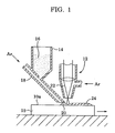
- a base material 10 of a size of 70x70x5 mm made of a carbon steel (Japanese Industrial Standard S45C) was positioned below a laser gun 12 and a powder feed hopper 14, and then the powder mixture was charged as indicated by 16 into the hopper.
- the powder mixture was continually supplied onto a center line portion of the surface 10a of 70x70 mm of the base material 10 which was moved rightward in the figure, so that a powder layer 20 was formed thereon and irradiated by laser beams 22 to be melted into a form of molten weld bead 24 according to the conditions described below.
- the molten weld bead and the surface portion of the base material were rapidly cooled down by the heat thereof being absorbed by the body portion of the base material.
- Fig. 2 is an optically microscopic photograph showing the metallurgical structure in a cross section of the weld bead taken in a direction perpendicular to the direction of extension of the weld bead as magnified 10 times.
- the white portion in the weld bead adjoining the base material is formed of the auxiliary metal, and the bright portion thereabove is principally made of pure copper. From Fig. 2 it will be appreciated that the weld bead is formed in good condition.
- FIG. 6 is an optically microscopic photograph showing the metallurgical structure in a cross section of the weld bead taken in a direction perpendicular to the direction of extension of the weld bead thus obtained as magnified 10 times. From Fig. 6 it will be appreciated that weld bead was also formed in good condition when the base material is a cast iron so as to include a layer of the auxiliary metal adjoining the base material and a layer of pure copper formed thereon.
- Figs. 7-15 are optically microscopic photographs showing the metallurgical structures in cross sections of the weld beads thus obtained corresponding to powder mixture Nos. 1-9 taken in a direction perpendicular to the direction of extension of each of the weld beads as magnified 10 times.
- the white or bright grey portions are principally made of the auxiliary metals and the black or dark grey portions are principally made of copper.
- the nickel content of the powder mixture should desirably be not more than 16 wt%, more desirably not more than 13 wt%.
- the Vicker's hardness Hv under the load of 5 kg was measured with respect to the surface portions of the weld beads. The results are shown in Fig. 16. From this figure it will be appreciated that when a weld bead having high purity of copper is to be formed on a carbon steel, the nickel content of the powder mixture should desirably be not more than 16 wt%, more desirably not more than 15 wt%, and further more desirably not more than 13 wt%.
- the copper content of the powder mixture should desirably be not less than 40 wt%, more desirably not less than 50 wt%, in order to avoid cracking of the weld bead, and that the copper content of the powder mixture should desirably be not more than 95 wt%, more desirably not more than 90 wt%, in order to obtain high efficiency of welding of the powder mixture to the base material.
- the molten metal formed by melting of the powder mixture starts to solidify at a portion thereof adjoining the base material. Since the auxiliary metal in the molten metal has a higher melting point than pure copper, the auxiliary metal starts to solidify prior to pure copper so as first to form a solidified layer of the auxiliary metal adjacent the base material, before the remaining copper solidifies to form a solidified layer thereof on the layer of the solidified auxiliary metal. Since the content of nickel which is co-solidifiable with copper at any rate is set to be not more than 16 wt%, it is avoided that the purity of copper of the layer finally solidified lowers by mixing of the nickel therein.
- a weld bead having a double layer structure having a layer of the auxiliary metal formed adjacent the base material and a copper layer having high copper content formed thereon.
- the powder of copper is beforehand mixed with a powder of an auxiliary metal having a higher melting point than pure copper.
- the powder mixture should not include more than 16 wt% nickel.
Landscapes
- Engineering & Computer Science (AREA)
- Mechanical Engineering (AREA)
- Physics & Mathematics (AREA)
- Optics & Photonics (AREA)
- Plasma & Fusion (AREA)
- Chemical & Material Sciences (AREA)
- Materials Engineering (AREA)
- Metallurgy (AREA)
- Organic Chemistry (AREA)
- Laser Beam Processing (AREA)
- Welding Or Cutting Using Electron Beams (AREA)
Description
- The present invention relates to a method of forming a weld bead of metal, and more particularly a method of forming a weld bead of pure copper on a ferroalloy base material.
- It is already known to provide a coating membrane of copper or a copper alloy on the surface of a cast iron material and thereafter to melt the coating membrane by a high density energy source so as thereby to turn the coating membrane into a weld bead, as disclosed, for example, in Japanese Patent Laid-open Publication 62-101392 & EP-A-0 221 752. According to this method it is possible to obtain a weld bead having no cracks or blow holes. EP-A-0 344 310 relates to a laser padding material for the formation of surface layer resistant to abrasion and sliding on a iron base. The padding material does not comprise iron and in the process an copper_alloy is formed.
- However, when this method is used for copper in such a manner that a powder of pure copper is laid on the surface of a cast iron material and the powder is melted by a high density energy source in order to form a weld bead of pure copper on the cast iron material, the graphite in the cast iron diffuses into the coating membrane, and therefore a weld bead having a high copper content can not be formed on the base material.
- As a result of various experimental researches in an effort for forming a weld bead of pure copper on a cast iron material in view of the above-mentioned problem, the inventors of the present application have succeeded in forming a weld bead having a high copper content on a ferroalloy base material by mixing a powder of pure copper with a powder of an auxiliary metal which satisfies certain particular conditions.
- Therefore, it is the object of the present invention to provide a method of forming a weld bead having high copper content on a ferroalloy base material.
- According to the present invention, such an object is accomplished by a method of forming a weld bead of pure copper on a ferroalloy base material comprising the steps of laying a mixture of a powder of pure copper and a powder of an auxiliary metal having a higher melting point than pure copper, said powder mixture including not more than 16 wt% nickel, and melting said powder mixture by a high density energy source.
- According to the present invention a powder of pure copper is mixed with a powder of an auxiliary metal having a higher melting point than pure copper and comprising iron to provide a powder mixture in which the nickel content is not more than 16 wt%, and then the powder mixture is laid on a ferroalloy base material and is melted by a high density energy source as set out in claim 1. Preferred embodiments of the process defined in claim 1 are given in the dependent claims.
- As a molten metal formed by melting of the powder mixture is principally cooled down by heat conduction to the ferroalloy base material, the solidification of the molten metal starts at a portion thereof defining a border contacting the base material. Since the auxiliary metal has a higher melting point than pure copper, the auxiliary metal starts to solidify prior to pure copper, thereby forming a solidified layer of the auxiliary metal on the surface of the base material before the pure copper in the mixture solidifies on the solidified layer of the auxiliary metal, thereby maintaining high purity of copper content.
- The nickel content of the powder mixture has an effect of improving the tightness and tenacity of the layer substantially formed from the auxiliary metal and the integrity of such an intermediate layer with the principal body of the weld bead. Since the content of the nickel which is co-solidifiable with copper at any rate is not more than 16 wt%, it is avoided that the purity of copper of the weld bead is substantially affected by the nickel in the mixture being retained in the body of the weld bead, as will be appreciated by the results of the experimental researches conducted by the inventors and described hereinunder. The minimum value for the nickel content to obtain the above-mentioned effects is not critically determined. However, it is desirable that the nickel content is not less than 4 wt%.
- According to the experimental researches conducted by the inventors, it is possible to obtain a weld bead having a very high purity of copper when the nickel content is not higher than 15 wt%, particularly not higher than 13 wt%. Therefore, according to a detailed feature of the present invention, the nickel content of the powder mixture is set to be not more than 15 wt%, more desirably not more than 13 wt%.
- Further, according to the results of the experimental researches conducted by the inventors, the weld bead is liable to cracking when the content of pure copper of the powder mixture is less than 60 wt%, particularly less than 50 wt%, whereas the efficiency of welding of the powder mixture to the base material lowers when the content of pure copper of the powder mixture is more than 90 wt%, particularly more than 95 wt%. Therefore, according to another detailed feature of the present invention, the copper content of the powder mixture is set to be 50-95 wt%, more desirably 60-90 wt%.
- Further, according to the results of the experimental researches conducted by the inventors, when laser beams are used for the high density energy source, it is desirable that the powder of the auxiliary metal includes B, Si or C, wherein it is desirable that the total amount of these elements in the powder mixture is 0.5-7.5 wt%, particularly 1.0-5.0 wt%. Therefore, according to a further detailed feature of the present invention, the total content of B, Si and C of the powder mixture is set to be 0.5-7.5 wt%, more desirably 1.0-5.0 wt%.
- Further, according to the results of the experimental researches conducted by the inventors, it is desirable that the solubility of the metal elements forming the auxiliary powder to copper at room temperature is not more than 0.5 wt%. Therefore, according to a further detailed feature of the present invention, the metal elements forming the auxiliary powder are selected so that the solubility thereof to copper at room temperature is not more than 0.5 wt%.
- The high density energy source for the method according to the present invention may be laser beams, TIG arc or electron beams. Laser beams are more widely usable than other high density energy sources when the electric resistance of the powder mixture or the base material is relatively high and are superior to others in adjustability of focus so that the range of heating applied to the powder mixture is relatively easily controlled. TIG arc and electron beams are superior to laser beams in that the molten metal generated from the powder mixture is agitated by the electromagnetic effect. While the environment for electron beams should generally be vacuum, an inert gas atmosphere may be used for laser beams and TIG arc, allowing for higher efficiency of work with less equipments than electron beams. Electron beams are superior to others when a very small area is to be heated.
- The powder mixture may simply be laid on the surface of the base material beforehand, or, when laser beams or electron beams are used for the high density energy source, the powder mixture may be successively supplied onto the surface of the base material along the line of scanning of the laser or electron beams as they proceed.
- In the accompanying drawings,
- Fig. 1 is a sectional view showing a manner of forming a weld bead according to an embodiment of the method of the present invention;
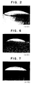
- Fig. 2 is an optically microscopic photograph showing the metallurgical structure in a cross section of the weld bead formed on the base material of a carbon steel taken in a direction perpendicular to the direction of extension of the weld bead as magnified 10 times;
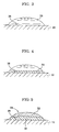
- Figs. 3-5 are illustrations of the solidifying process of the molten metal according to the method of the present invention;
- Fig. 6 is an optically microscopic photograph showing the metallurgical structure in a cross section of the weld bead formed on the base material of a cast iron taken in a direction perpendicular to the direction of extension of the weld bead as magnified 10 times;
- Figs. 7-15 are optically microscopic photographs showing the metallurgical structures in cross sections of the weld beads formed by varying the mixing ratio among pure copper powder and two kinds of auxiliary metals taken in a direction perpendicular to the direction of extension of the weld bead as magnified 10 times;
- Fig. 16 is a graph showing the relation between the nickel content of the powder mixture and the surface hardness of the weld bead; and
- Fig. 17 is a graph showing the relation between the copper content of the powder mixture and the cracking rate of the weld bead and the efficiency of welding of the powder mixture to the base material.
- In the following the present invention will be described in more detail in the form of some preferred embodiments with reference to the accompanying drawings.
- First, a pure copper powder having an average particle size of 74 microns and a melting point of 1083 °C and a powder of the auxiliary metal were prepared, wherein the auxiliary metal was "FP230" manufactured by Fukuda Kinzoku Kabushiki Kaisha and having an average particle size of 74 microns and a melting point of 1220 °C and including 15 wt% Ni, 19.5 wt% Cr, 0.5 wt% B, 3.8 wt% Si, 0.1 wt% C, 2.8 wt% W, 1.0 wt% Mn, 0.5 wt% Mo, 2.5 wt% Co and remainder Fe. These powders were mixed with one another at a ratio by weight of 80 vs. 20.
- On the other hand, as shown in Fig. 1, a
base material 10 of a size of 70x70x5 mm made of a carbon steel (Japanese Industrial Standard S45C) was positioned below alaser gun 12 and apowder feed hopper 14, and then the powder mixture was charged as indicated by 16 into the hopper. Then, while ejecting an assist gas from the tip of thelaser gun 12 and supplying argon as a carrier gas through aconduit 18, the powder mixture was continually supplied onto a center line portion of thesurface 10a of 70x70 mm of thebase material 10 which was moved rightward in the figure, so that apowder layer 20 was formed thereon and irradiated bylaser beams 22 to be melted into a form ofmolten weld bead 24 according to the conditions described below. The molten weld bead and the surface portion of the base material were rapidly cooled down by the heat thereof being absorbed by the body portion of the base material.
- Fig. 2 is an optically microscopic photograph showing the metallurgical structure in a cross section of the weld bead taken in a direction perpendicular to the direction of extension of the weld bead as magnified 10 times. In Fig. 2, the white portion in the weld bead adjoining the base material is formed of the auxiliary metal, and the bright portion thereabove is principally made of pure copper. From Fig. 2 it will be appreciated that the weld bead is formed in good condition.
- It is considered that such a result was obtained through a solidifying process of the molten metal generated by melting of the powder mixture as illustrated in Figs. 3 to 5. Referring to these figures, when the metals of the powder mixture are in a completely molten state as shown in Fig. 3, the pure copper and the auxiliary metal are substantially mixed with one another. However, since the
molten metal 26 is cooled down principally by the conduction of heat to the base material, the solidification of the molten metal starts at aborder 28 contacting the base material. Since the auxiliary metal has a higher melting point than pure copper, the auxiliary metal starts to solidify prior to pure copper,. Therefore, alayer 30 of the solidified auxiliary metal is formed as shown in Fig. 4, before copper solidifies to form alayer 32 on thelayer 30 of the auxiliary metal as shown in Fig. 5, so that a double layered weld bead structure having theauxiliary metal layer 30 and thecopper layer 32 is finally obtained. - Another weld bead was formed in the same manner and under the same conditions as in Embodiment 1, except that a cast iron (Japanese Industrial Standard FC23) was used for the base material. Fig. 6 is an optically microscopic photograph showing the metallurgical structure in a cross section of the weld bead taken in a direction perpendicular to the direction of extension of the weld bead thus obtained as magnified 10 times. From Fig. 6 it will be appreciated that weld bead was also formed in good condition when the base material is a cast iron so as to include a layer of the auxiliary metal adjoining the base material and a layer of pure copper formed thereon.
- By using the same powder of pure copper and the powder of "FP230" as used in Embodiment 1, and further a powder of "FP430" also manufactured by Fukuda Kinzoku Kabushiki Kaisha and having an average particle size of 74 microns, a melting point of 1260 °C and a composition of 15 wt% Cr, 2 wt% W, 0.3 wt% C, 5 wt% Fe, 0.7 wt% B, 5 wt% Si and remainder Ni, nine powder mixtures numbered No. 1 to 9 were prepared at mixing ratios as shown in Table 2:
Table 2 No. Mixing ratio Ni content wt% Melting point °C FP230 FP430 Cu 1 18 2 80 4.1 1220-1230 2 45 5 50 10.4 1220-1230 3 40 10 50 13.2 1220-1230 4 35 15 50 16.1 1220-1240 5 30 20 50 19.9 1220-1240 6 25 25 50 21.8 1230-1250 7 20 30 50 24.6 1240-1260 8 15 35 50 27.5 1240-1260 9 10 40 50 30.3 1240-1260 - Then, by using these powder mixtures weld beads were formed in the same manner and under the same conditions as in Embodiment 1. Figs. 7-15 are optically microscopic photographs showing the metallurgical structures in cross sections of the weld beads thus obtained corresponding to powder mixture Nos. 1-9 taken in a direction perpendicular to the direction of extension of each of the weld beads as magnified 10 times. In these photographs, the white or bright grey portions are principally made of the auxiliary metals and the black or dark grey portions are principally made of copper.
- From these photographs it will be appreciated that the nickel content of the powder mixture should desirably be not more than 16 wt%, more desirably not more than 13 wt%.
- The Vicker's hardness Hv under the load of 5 kg was measured with respect to the surface portions of the weld beads. The results are shown in Fig. 16. From this figure it will be appreciated that when a weld bead having high purity of copper is to be formed on a carbon steel, the nickel content of the powder mixture should desirably be not more than 16 wt%, more desirably not more than 15 wt%, and further more desirably not more than 13 wt%.
- There is an inverse relation between the hardness and the purity of copper of the surface portion of the weld bead. In other word, the hardness is lower as the purity of copper is higher. Therefore, it is possible to estimate the purity of copper of the surface portion of the bead from measurement of the hardness thereof.
- Weld beads were formed in the same manner and under the same conditions as in Embodiment 1, except that the pure copper powder and the "FP230" powder were mixed in various mixing ratios. Then, a cracking rate was measured as the number of cracks generated in 1 cm² cross section of the weld bead, and an efficiency of welding of the powder material to the base material was measured as a ratio of the weight of the weld bead formed on the base material to the weight of the powder mixture supplied to form the weld bead. The results are shown in Fig. 17.
- From Fig. 17 it will be appreciated that the copper content of the powder mixture should desirably be not less than 40 wt%, more desirably not less than 50 wt%, in order to avoid cracking of the weld bead, and that the copper content of the powder mixture should desirably be not more than 95 wt%, more desirably not more than 90 wt%, in order to obtain high efficiency of welding of the powder mixture to the base material.
- Further, it was also confirmed that, when the base material in Examples 1 and 2 was replaced by a cast iron (Japanese Industrial Standard FC23), substantially the same results were obtained. Further, it was also confirmed that, when the auxiliary metal in Example 2 was replaced by "FP430" used in Example 1, substantially the same results as shown in Fig. 17 were obtained.
- As will be apparent from the foregoing, the molten metal formed by melting of the powder mixture starts to solidify at a portion thereof adjoining the base material. Since the auxiliary metal in the molten metal has a higher melting point than pure copper, the auxiliary metal starts to solidify prior to pure copper so as first to form a solidified layer of the auxiliary metal adjacent the base material, before the remaining copper solidifies to form a solidified layer thereof on the layer of the solidified auxiliary metal. Since the content of nickel which is co-solidifiable with copper at any rate is set to be not more than 16 wt%, it is avoided that the purity of copper of the layer finally solidified lowers by mixing of the nickel therein.
- Therefore, according to the present invention it is possible to obtain a weld bead having a double layer structure having a layer of the auxiliary metal formed adjacent the base material and a copper layer having high copper content formed thereon.
- In forming a weld bead of pure copper on a ferroalloy base material by laying a powder of copper and melting the powder by a high density energy source such as laser beams, TIG arc or electron beams, the powder of copper is beforehand mixed with a powder of an auxiliary metal having a higher melting point than pure copper. In order to ensure the substantial purity in copper of the weld bead, the powder mixture should not include more than 16 wt% nickel.
Claims (11)
- A method of forming a weld bead of pure copper on a ferroalloy base material comprising the steps of laying a mixture of a powder of pure copper and a powder of an auxiliary metal having a higher melting point than pure copper and comprising iron, said powder mixture including not more than 16 wt% nickel, and melting said powder mixture by a high density energy source.
- A method according to claim 1, wherein the nickel content of the powder mixture is not more than 15 wt%.
- A method according to claim 1, wherein the nickel content of the powder mixture is not more than 13 wt%.
- A method according to claim 1, 2 or 3, wherein the nickel content of the powder mixture is not less than than 4 wt%.
- A method according to any one of claims 1-4, wherein the copper content of the powder mixture is 50-95 wt%.
- A method according to any one of claims 1-4, wherein the copper content of the powder mixture is 60-90 wt%.
- A method according to any one of claims 1-6, wherein the total content of B, Si and C of the powder mixture, when these elements are included, is 0.5-7.5 wt%.
- A method according to claim 7, wherein the total content of B, Si and C of the powder mixture is 1.0-5.0 wt%.
- A method according to any one of claims 1-8, wherein the metal elements forming the auxiliary powder are selected so that the solubility thereof to copper at room temperature is not more than 0.5 wt%.
- A method according to any one of claims 1-9, wherein the high density energy source is selected from laser beams, TIG arc and electron beams.
- A method according to claim 10, wherein when laser beams or electron beams are used for the high density energy source, the powder mixture is successively supplied onto the surface of the base material along a line of scanning of the laser or electron beams as they proceed.
Applications Claiming Priority (2)
| Application Number | Priority Date | Filing Date | Title |
|---|---|---|---|
| JP2092796A JP2678804B2 (en) | 1990-04-06 | 1990-04-06 | Method for forming pure Cu build-up layer on iron alloy substrate |
| JP92796/90 | 1990-04-06 |
Publications (2)
| Publication Number | Publication Date |
|---|---|
| EP0450617A1 EP0450617A1 (en) | 1991-10-09 |
| EP0450617B1 true EP0450617B1 (en) | 1995-07-05 |
Family
ID=14064385
Family Applications (1)
| Application Number | Title | Priority Date | Filing Date |
|---|---|---|---|
| EP91105340A Expired - Lifetime EP0450617B1 (en) | 1990-04-06 | 1991-04-04 | Method of forming weld bead of pure copper on ferroalloy base material |
Country Status (5)
| Country | Link |
|---|---|
| US (1) | US5230756A (en) |
| EP (1) | EP0450617B1 (en) |
| JP (1) | JP2678804B2 (en) |
| CA (1) | CA2039657C (en) |
| DE (1) | DE69110938T2 (en) |
Families Citing this family (19)
| Publication number | Priority date | Publication date | Assignee | Title |
|---|---|---|---|---|
| JP2535652B2 (en) * | 1990-07-24 | 1996-09-18 | 株式会社小松製作所 | Laser cladding and alloying method |
| US5281772A (en) * | 1991-10-28 | 1994-01-25 | Delco Electronics Corporation | Electrical connector having energy-formed solder stops and methods of making and using the same |
| SE9303245L (en) * | 1993-10-05 | 1995-04-06 | Johan Lennart Olofsson | Procedure for improving certain properties of railway wheels |
| FR2799401B1 (en) * | 1999-10-07 | 2002-01-18 | Framatome Sa | PROTECTION METHOD AND METHOD FOR RENOVATION OF A HETEROGENEOUS WELDED LINK BETWEEN TWO TUBULAR ELEMENTS |
| CA2336558C (en) * | 2000-02-22 | 2005-02-01 | Honda Giken Kogyo Kabushiki Kaisha | Die assembly and method of making die assembly |
| US20060051508A1 (en) * | 2000-12-28 | 2006-03-09 | Ilan Gavish | Focused ion beam deposition |
| US6492261B2 (en) * | 2000-12-30 | 2002-12-10 | Intel Corporation | Focused ion beam metal deposition |
| US6638580B2 (en) * | 2000-12-29 | 2003-10-28 | Intel Corporation | Apparatus and a method for forming an alloy layer over a substrate using an ion beam |
| GB2418166A (en) * | 2004-09-15 | 2006-03-22 | Rolls Royce Plc | Component fabrication using electron beam deposition welding |
| US8685501B2 (en) * | 2004-10-07 | 2014-04-01 | Lockheed Martin Corporation | Co-continuous metal-metal matrix composite material using timed deposition processing |
| US20060075850A1 (en) * | 2004-10-07 | 2006-04-13 | Lockheed Martin Corporation | Nitrogen-modified titanium and method of producing same |
| US20070012138A1 (en) * | 2004-10-28 | 2007-01-18 | Lockheed Martin Corporation | Gas-phase alloying of metallic materials |
| JP4802895B2 (en) * | 2006-07-05 | 2011-10-26 | トヨタ自動車株式会社 | Cast iron member manufacturing method, cast iron member, and vehicle engine |
| JP2009285675A (en) * | 2008-05-28 | 2009-12-10 | Toyota Motor Corp | Overlaying method |
| DE102012204927B3 (en) * | 2012-03-27 | 2013-07-04 | Thomas Ammersbach | A job-welded workpiece and method of making a job-welded workpiece |
| DE102013016452A1 (en) * | 2013-10-02 | 2015-04-02 | Linde Aktiengesellschaft | Process for gas metal arc welding |
| JP2018029090A (en) * | 2014-11-26 | 2018-02-22 | 株式会社日立製作所 | Dissimilar metal joint structure, manufacturing method thereof, and water-cooled power conversion element including the same |
| CN108453353B (en) * | 2018-04-24 | 2020-06-26 | 今创集团股份有限公司 | Welding method of red copper |
| CN114523111B (en) * | 2022-01-13 | 2024-04-16 | 西安理工大学 | Method for carrying out surface strengthening on copper-based powder metallurgy component by adopting arc remelting |
Family Cites Families (7)
| Publication number | Priority date | Publication date | Assignee | Title |
|---|---|---|---|---|
| US2427517A (en) * | 1943-09-18 | 1947-09-16 | Lincoln Electric Co | Method of making an electrical contact member containing commingled copper and steel |
| BR7806091A (en) * | 1978-09-15 | 1980-03-25 | Metal Leve Sa Ind Com | PROCESS FOR THE BENEFIT OF ANTI-FRICTION ALLOY STEEL COATING ALLOYS, THE BENEFIT COMPOUND STRIPS AND PRODUCTS OBTAINED FROM SUCH STRIPS |
| JPS62101392A (en) * | 1985-10-29 | 1987-05-11 | Toyota Motor Corp | Filling method for cast iron material utilizing high density energy source |
| JPH0698506B2 (en) * | 1986-12-08 | 1994-12-07 | トヨタ自動車株式会社 | Method for forming dispersed alloy layer on metal substrate |
| JPS63149347A (en) * | 1986-12-15 | 1988-06-22 | Komatsu Ltd | Copper alloy for high sliding wear resistance for laser welding |
| JPH08942B2 (en) * | 1986-12-19 | 1996-01-10 | トヨタ自動車株式会社 | Dispersion strengthened Cu-based alloy |
| JPH01215941A (en) * | 1988-02-24 | 1989-08-29 | Toyota Motor Corp | Dispersion strengthened cu-based alloy |
-
1990
- 1990-04-06 JP JP2092796A patent/JP2678804B2/en not_active Expired - Fee Related
-
1991
- 1991-04-03 CA CA002039657A patent/CA2039657C/en not_active Expired - Fee Related
- 1991-04-03 US US07/680,062 patent/US5230756A/en not_active Expired - Fee Related
- 1991-04-04 EP EP91105340A patent/EP0450617B1/en not_active Expired - Lifetime
- 1991-04-04 DE DE69110938T patent/DE69110938T2/en not_active Expired - Fee Related
Also Published As
| Publication number | Publication date |
|---|---|
| EP0450617A1 (en) | 1991-10-09 |
| JP2678804B2 (en) | 1997-11-19 |
| JPH03291183A (en) | 1991-12-20 |
| CA2039657C (en) | 1998-09-22 |
| CA2039657A1 (en) | 1991-10-07 |
| US5230756A (en) | 1993-07-27 |
| DE69110938T2 (en) | 1995-12-14 |
| DE69110938D1 (en) | 1995-08-10 |
Similar Documents
| Publication | Publication Date | Title |
|---|---|---|
| US5230756A (en) | Method of forming weld bead of pure copper on ferroalloy base material | |
| EP0445818B1 (en) | Method of modifying surface qualities of metallic articles and apparatus therefor | |
| US4732778A (en) | Method for forming composite layer by laser irradiation upon aluminum alloy substrate surface of powder mixture containing metal carbide ceramic particles, silicon, and metal element forming inter metallic compound with silicon | |
| US4746540A (en) | Method for forming alloy layer upon aluminum alloy substrate by irradiating with a CO2 laser, on substrate surface, alloy powder containing substance for alloying and silicon or bismuth | |
| EP0505172B1 (en) | Wear-resistant copper-base alloy | |
| JP2639949B2 (en) | Wear-resistant Cu-based alloy | |
| US5118919A (en) | Weld metal alloy for high yield strength and method of depositing same | |
| EP3371337B1 (en) | Method of layer-by-layer construction of a metallic part | |
| JP2019532816A (en) | Method of manufacturing a steel part including adding molten metal on a support part, and part obtained thereby | |
| KR101172016B1 (en) | Weld wire and process for manufacturing the weld wire | |
| EP0221752A2 (en) | High energy padding method utilizing coating containing copper | |
| JPS61296976A (en) | Formation of carbide ceramic particle dispersed composite metallic layer | |
| JP3997123B2 (en) | Iron-based powder material for forming iron-based sintered body and method for producing iron-based sintered body | |
| JPH10158766A (en) | Copper alloy with heat resistance and wear resistance | |
| JP2588444B2 (en) | Improved welding alloy for high yield strength and its welding method | |
| US20030098090A1 (en) | Surface coatings | |
| EP4674551A1 (en) | Wire arc additive manufacturing method | |
| JP2535652B2 (en) | Laser cladding and alloying method | |
| JPH06122076A (en) | Overlay welding method of oxide dispersed metal | |
| KR102310275B1 (en) | Brazing assembly and method for preventing surface oxidation | |
| JP2731968B2 (en) | Overlay welding method for titanium or titanium alloy surface | |
| JPH04362A (en) | Method and apparatus for surface reforming of metallic parts | |
| JPH01118397A (en) | Overlaying material | |
| JPH05148565A (en) | Method for producing particle-dispersed magnesium alloy using high energy density heat source | |
| JP2942299B2 (en) | Additive for surface hardening of aluminum |
Legal Events
| Date | Code | Title | Description |
|---|---|---|---|
| PUAI | Public reference made under article 153(3) epc to a published international application that has entered the european phase |
Free format text: ORIGINAL CODE: 0009012 |
|
| AK | Designated contracting states |
Kind code of ref document: A1 Designated state(s): DE FR GB |
|
| 17P | Request for examination filed |
Effective date: 19910920 |
|
| 17Q | First examination report despatched |
Effective date: 19931122 |
|
| GRAA | (expected) grant |
Free format text: ORIGINAL CODE: 0009210 |
|
| AK | Designated contracting states |
Kind code of ref document: B1 Designated state(s): DE FR GB |
|
| ET | Fr: translation filed | ||
| REF | Corresponds to: |
Ref document number: 69110938 Country of ref document: DE Date of ref document: 19950810 |
|
| PLBE | No opposition filed within time limit |
Free format text: ORIGINAL CODE: 0009261 |
|
| STAA | Information on the status of an ep patent application or granted ep patent |
Free format text: STATUS: NO OPPOSITION FILED WITHIN TIME LIMIT |
|
| 26N | No opposition filed | ||
| REG | Reference to a national code |
Ref country code: GB Ref legal event code: IF02 |
|
| PGFP | Annual fee paid to national office [announced via postgrant information from national office to epo] |
Ref country code: GB Payment date: 20040331 Year of fee payment: 14 |
|
| PGFP | Annual fee paid to national office [announced via postgrant information from national office to epo] |
Ref country code: FR Payment date: 20040408 Year of fee payment: 14 |
|
| PGFP | Annual fee paid to national office [announced via postgrant information from national office to epo] |
Ref country code: DE Payment date: 20040415 Year of fee payment: 14 |
|
| PG25 | Lapsed in a contracting state [announced via postgrant information from national office to epo] |
Ref country code: GB Free format text: LAPSE BECAUSE OF NON-PAYMENT OF DUE FEES Effective date: 20050404 |
|
| PG25 | Lapsed in a contracting state [announced via postgrant information from national office to epo] |
Ref country code: DE Free format text: LAPSE BECAUSE OF NON-PAYMENT OF DUE FEES Effective date: 20051101 |
|
| GBPC | Gb: european patent ceased through non-payment of renewal fee |
Effective date: 20050404 |
|
| PG25 | Lapsed in a contracting state [announced via postgrant information from national office to epo] |
Ref country code: FR Free format text: LAPSE BECAUSE OF NON-PAYMENT OF DUE FEES Effective date: 20051230 |
|
| REG | Reference to a national code |
Ref country code: FR Ref legal event code: ST Effective date: 20051230 |