EP0450530B1 - Fuel intake system for V-type combustion engine - Google Patents
Fuel intake system for V-type combustion engine Download PDFInfo
- Publication number
- EP0450530B1 EP0450530B1 EP91105073A EP91105073A EP0450530B1 EP 0450530 B1 EP0450530 B1 EP 0450530B1 EP 91105073 A EP91105073 A EP 91105073A EP 91105073 A EP91105073 A EP 91105073A EP 0450530 B1 EP0450530 B1 EP 0450530B1
- Authority
- EP
- European Patent Office
- Prior art keywords
- combustion engine
- passages
- crank axis
- tanks
- hand
- Prior art date
- Legal status (The legal status is an assumption and is not a legal conclusion. Google has not performed a legal analysis and makes no representation as to the accuracy of the status listed.)
- Expired - Lifetime
Links
- 238000002485 combustion reaction Methods 0.000 title claims description 56
- 239000000446 fuel Substances 0.000 title description 5
- 238000005192 partition Methods 0.000 claims description 18
- 238000011144 upstream manufacturing Methods 0.000 claims description 15
- 230000000694 effects Effects 0.000 claims description 2
- 238000010304 firing Methods 0.000 claims description 2
- 239000007789 gas Substances 0.000 description 9
- 230000001105 regulatory effect Effects 0.000 description 7
- 230000003134 recirculating effect Effects 0.000 description 5
- 238000009827 uniform distribution Methods 0.000 description 4
- 230000002411 adverse Effects 0.000 description 3
- 238000004891 communication Methods 0.000 description 2
- 238000013459 approach Methods 0.000 description 1
- 238000009826 distribution Methods 0.000 description 1
- 238000002347 injection Methods 0.000 description 1
- 239000007924 injection Substances 0.000 description 1
- 238000012986 modification Methods 0.000 description 1
- 230000004048 modification Effects 0.000 description 1
Images




Classifications
-
- F—MECHANICAL ENGINEERING; LIGHTING; HEATING; WEAPONS; BLASTING
- F02—COMBUSTION ENGINES; HOT-GAS OR COMBUSTION-PRODUCT ENGINE PLANTS
- F02M—SUPPLYING COMBUSTION ENGINES IN GENERAL WITH COMBUSTIBLE MIXTURES OR CONSTITUENTS THEREOF
- F02M35/00—Combustion-air cleaners, air intakes, intake silencers, or induction systems specially adapted for, or arranged on, internal-combustion engines
- F02M35/10—Air intakes; Induction systems
-
- F—MECHANICAL ENGINEERING; LIGHTING; HEATING; WEAPONS; BLASTING
- F02—COMBUSTION ENGINES; HOT-GAS OR COMBUSTION-PRODUCT ENGINE PLANTS
- F02M—SUPPLYING COMBUSTION ENGINES IN GENERAL WITH COMBUSTIBLE MIXTURES OR CONSTITUENTS THEREOF
- F02M35/00—Combustion-air cleaners, air intakes, intake silencers, or induction systems specially adapted for, or arranged on, internal-combustion engines
- F02M35/10—Air intakes; Induction systems
- F02M35/10091—Air intakes; Induction systems characterised by details of intake ducts: shapes; connections; arrangements
- F02M35/10131—Ducts situated in more than one plane; Ducts of one plane crossing ducts of another plane
-
- F—MECHANICAL ENGINEERING; LIGHTING; HEATING; WEAPONS; BLASTING
- F02—COMBUSTION ENGINES; HOT-GAS OR COMBUSTION-PRODUCT ENGINE PLANTS
- F02B—INTERNAL-COMBUSTION PISTON ENGINES; COMBUSTION ENGINES IN GENERAL
- F02B27/00—Use of kinetic or wave energy of charge in induction systems, or of combustion residues in exhaust systems, for improving quantity of charge or for increasing removal of combustion residues
- F02B27/005—Oscillating pipes with charging achieved by arrangement, dimensions or shapes of intakes pipes or chambers; Ram air pipes
- F02B27/006—Oscillating pipes with charging achieved by arrangement, dimensions or shapes of intakes pipes or chambers; Ram air pipes of intake runners
-
- F—MECHANICAL ENGINEERING; LIGHTING; HEATING; WEAPONS; BLASTING
- F02—COMBUSTION ENGINES; HOT-GAS OR COMBUSTION-PRODUCT ENGINE PLANTS
- F02B—INTERNAL-COMBUSTION PISTON ENGINES; COMBUSTION ENGINES IN GENERAL
- F02B27/00—Use of kinetic or wave energy of charge in induction systems, or of combustion residues in exhaust systems, for improving quantity of charge or for increasing removal of combustion residues
- F02B27/008—Resonance charging
-
- F—MECHANICAL ENGINEERING; LIGHTING; HEATING; WEAPONS; BLASTING
- F02—COMBUSTION ENGINES; HOT-GAS OR COMBUSTION-PRODUCT ENGINE PLANTS
- F02B—INTERNAL-COMBUSTION PISTON ENGINES; COMBUSTION ENGINES IN GENERAL
- F02B27/00—Use of kinetic or wave energy of charge in induction systems, or of combustion residues in exhaust systems, for improving quantity of charge or for increasing removal of combustion residues
- F02B27/02—Use of kinetic or wave energy of charge in induction systems, or of combustion residues in exhaust systems, for improving quantity of charge or for increasing removal of combustion residues the systems having variable, i.e. adjustable, cross-sectional areas, chambers of variable volume, or like variable means
- F02B27/0205—Use of kinetic or wave energy of charge in induction systems, or of combustion residues in exhaust systems, for improving quantity of charge or for increasing removal of combustion residues the systems having variable, i.e. adjustable, cross-sectional areas, chambers of variable volume, or like variable means characterised by the charging effect
- F02B27/0215—Oscillating pipe charging, i.e. variable intake pipe length charging
- F02B27/0221—Resonance charging combined with oscillating pipe charging
-
- F—MECHANICAL ENGINEERING; LIGHTING; HEATING; WEAPONS; BLASTING
- F02—COMBUSTION ENGINES; HOT-GAS OR COMBUSTION-PRODUCT ENGINE PLANTS
- F02B—INTERNAL-COMBUSTION PISTON ENGINES; COMBUSTION ENGINES IN GENERAL
- F02B27/00—Use of kinetic or wave energy of charge in induction systems, or of combustion residues in exhaust systems, for improving quantity of charge or for increasing removal of combustion residues
- F02B27/02—Use of kinetic or wave energy of charge in induction systems, or of combustion residues in exhaust systems, for improving quantity of charge or for increasing removal of combustion residues the systems having variable, i.e. adjustable, cross-sectional areas, chambers of variable volume, or like variable means
- F02B27/0226—Use of kinetic or wave energy of charge in induction systems, or of combustion residues in exhaust systems, for improving quantity of charge or for increasing removal of combustion residues the systems having variable, i.e. adjustable, cross-sectional areas, chambers of variable volume, or like variable means characterised by the means generating the charging effect
- F02B27/0247—Plenum chambers; Resonance chambers or resonance pipes
- F02B27/0252—Multiple plenum chambers or plenum chambers having inner separation walls, e.g. comprising valves for the same group of cylinders
-
- F—MECHANICAL ENGINEERING; LIGHTING; HEATING; WEAPONS; BLASTING
- F02—COMBUSTION ENGINES; HOT-GAS OR COMBUSTION-PRODUCT ENGINE PLANTS
- F02M—SUPPLYING COMBUSTION ENGINES IN GENERAL WITH COMBUSTIBLE MIXTURES OR CONSTITUENTS THEREOF
- F02M26/00—Engine-pertinent apparatus for adding exhaust gases to combustion-air, main fuel or fuel-air mixture, e.g. by exhaust gas recirculation [EGR] systems
- F02M26/13—Arrangement or layout of EGR passages, e.g. in relation to specific engine parts or for incorporation of accessories
- F02M26/17—Arrangement or layout of EGR passages, e.g. in relation to specific engine parts or for incorporation of accessories in relation to the intake system
-
- F—MECHANICAL ENGINEERING; LIGHTING; HEATING; WEAPONS; BLASTING
- F02—COMBUSTION ENGINES; HOT-GAS OR COMBUSTION-PRODUCT ENGINE PLANTS
- F02M—SUPPLYING COMBUSTION ENGINES IN GENERAL WITH COMBUSTIBLE MIXTURES OR CONSTITUENTS THEREOF
- F02M35/00—Combustion-air cleaners, air intakes, intake silencers, or induction systems specially adapted for, or arranged on, internal-combustion engines
- F02M35/10—Air intakes; Induction systems
- F02M35/10006—Air intakes; Induction systems characterised by the position of elements of the air intake system in direction of the air intake flow, i.e. between ambient air inlet and supply to the combustion chamber
- F02M35/10026—Plenum chambers
- F02M35/10032—Plenum chambers specially shaped or arranged connecting duct between carburettor or air inlet duct and the plenum chamber; specially positioned carburettors or throttle bodies with respect to the plenum chamber
-
- F—MECHANICAL ENGINEERING; LIGHTING; HEATING; WEAPONS; BLASTING
- F02—COMBUSTION ENGINES; HOT-GAS OR COMBUSTION-PRODUCT ENGINE PLANTS
- F02M—SUPPLYING COMBUSTION ENGINES IN GENERAL WITH COMBUSTIBLE MIXTURES OR CONSTITUENTS THEREOF
- F02M35/00—Combustion-air cleaners, air intakes, intake silencers, or induction systems specially adapted for, or arranged on, internal-combustion engines
- F02M35/10—Air intakes; Induction systems
- F02M35/10006—Air intakes; Induction systems characterised by the position of elements of the air intake system in direction of the air intake flow, i.e. between ambient air inlet and supply to the combustion chamber
- F02M35/10026—Plenum chambers
- F02M35/10045—Multiple plenum chambers; Plenum chambers having inner separation walls
-
- F—MECHANICAL ENGINEERING; LIGHTING; HEATING; WEAPONS; BLASTING
- F02—COMBUSTION ENGINES; HOT-GAS OR COMBUSTION-PRODUCT ENGINE PLANTS
- F02M—SUPPLYING COMBUSTION ENGINES IN GENERAL WITH COMBUSTIBLE MIXTURES OR CONSTITUENTS THEREOF
- F02M35/00—Combustion-air cleaners, air intakes, intake silencers, or induction systems specially adapted for, or arranged on, internal-combustion engines
- F02M35/10—Air intakes; Induction systems
- F02M35/10209—Fluid connections to the air intake system; their arrangement of pipes, valves or the like
- F02M35/10222—Exhaust gas recirculation [EGR]; Positive crankcase ventilation [PCV]; Additional air admission, lubricant or fuel vapour admission
-
- F—MECHANICAL ENGINEERING; LIGHTING; HEATING; WEAPONS; BLASTING
- F02—COMBUSTION ENGINES; HOT-GAS OR COMBUSTION-PRODUCT ENGINE PLANTS
- F02M—SUPPLYING COMBUSTION ENGINES IN GENERAL WITH COMBUSTIBLE MIXTURES OR CONSTITUENTS THEREOF
- F02M35/00—Combustion-air cleaners, air intakes, intake silencers, or induction systems specially adapted for, or arranged on, internal-combustion engines
- F02M35/10—Air intakes; Induction systems
- F02M35/104—Intake manifolds
- F02M35/116—Intake manifolds for engines with cylinders in V-arrangement or arranged oppositely relative to the main shaft
-
- F—MECHANICAL ENGINEERING; LIGHTING; HEATING; WEAPONS; BLASTING
- F02—COMBUSTION ENGINES; HOT-GAS OR COMBUSTION-PRODUCT ENGINE PLANTS
- F02M—SUPPLYING COMBUSTION ENGINES IN GENERAL WITH COMBUSTIBLE MIXTURES OR CONSTITUENTS THEREOF
- F02M35/00—Combustion-air cleaners, air intakes, intake silencers, or induction systems specially adapted for, or arranged on, internal-combustion engines
- F02M35/16—Combustion-air cleaners, air intakes, intake silencers, or induction systems specially adapted for, or arranged on, internal-combustion engines characterised by use in vehicles
- F02M35/161—Arrangement of the air intake system in the engine compartment, e.g. with respect to the bonnet or the vehicle front face
-
- F—MECHANICAL ENGINEERING; LIGHTING; HEATING; WEAPONS; BLASTING
- F02—COMBUSTION ENGINES; HOT-GAS OR COMBUSTION-PRODUCT ENGINE PLANTS
- F02B—INTERNAL-COMBUSTION PISTON ENGINES; COMBUSTION ENGINES IN GENERAL
- F02B75/00—Other engines
- F02B75/16—Engines characterised by number of cylinders, e.g. single-cylinder engines
- F02B75/18—Multi-cylinder engines
- F02B2075/1804—Number of cylinders
- F02B2075/1848—Number of cylinders twelve
-
- F—MECHANICAL ENGINEERING; LIGHTING; HEATING; WEAPONS; BLASTING
- F02—COMBUSTION ENGINES; HOT-GAS OR COMBUSTION-PRODUCT ENGINE PLANTS
- F02B—INTERNAL-COMBUSTION PISTON ENGINES; COMBUSTION ENGINES IN GENERAL
- F02B75/00—Other engines
- F02B75/16—Engines characterised by number of cylinders, e.g. single-cylinder engines
- F02B75/18—Multi-cylinder engines
- F02B75/22—Multi-cylinder engines with cylinders in V, fan, or star arrangement
-
- Y—GENERAL TAGGING OF NEW TECHNOLOGICAL DEVELOPMENTS; GENERAL TAGGING OF CROSS-SECTIONAL TECHNOLOGIES SPANNING OVER SEVERAL SECTIONS OF THE IPC; TECHNICAL SUBJECTS COVERED BY FORMER USPC CROSS-REFERENCE ART COLLECTIONS [XRACs] AND DIGESTS
- Y02—TECHNOLOGIES OR APPLICATIONS FOR MITIGATION OR ADAPTATION AGAINST CLIMATE CHANGE
- Y02T—CLIMATE CHANGE MITIGATION TECHNOLOGIES RELATED TO TRANSPORTATION
- Y02T10/00—Road transport of goods or passengers
- Y02T10/10—Internal combustion engine [ICE] based vehicles
- Y02T10/12—Improving ICE efficiencies
Definitions
- the present invention generally relates to an air intake system for a V-type combustion engine of an automotive vehicle and, more particularly, to the automobile air intake system employed in a multi-cylinder automobile combustion engine having V-shaped cylinder banks.
- the length of the engine cylinder block tends to have an increased length accompanied by the necessity of use of a crankshaft of correspondingly increased length.
- the increase in length of the engine cylinder block poses a problem associated with a proper distribution of intake air for each cylinder bank in a direction generally parallel to the crank axis along which the crankshaft extends.
- the air intake system as disclosed in US-A-4,763,612, which can be considered as the closest prior art and comprising the features of the preamble of claim 1 utilizes such a throttle casing, which is located in the space in front of the cylinder banks, thus increasing their length and making it more difficult to obtain a uniform distribution of intake air, especially since the air supply to each surge tank via the connections takes place at a surge tank sidewall extending parallel to the crank axis and at an end wall transverse thereto.
- US-A-3,303,832 discloses another air intake system which comprises the features of the generic part of claim 1 except for the throttle casing being formed such that air is sucked therethrough in a vertical direction transverse to the crank axis.
- the present invention has been devised in consideration of the foregoing circumstances found in the prior art internal combustion engine of the type having V-shaped cylinder banks and is intended to provide an improved air intake system for the internal combustion engine of the type having the V-shaped cylinder banks, wherein the throttle casing is disposed within a generally V-shaped longitudinal center space delimited between the cylinder banks and also wherein a substantially uniform distribution of the intake air is secured in a direction generally parallel to the crank axis.
- the throttle casing is disposed above the V-shaped longitudinal center space delimited between the cylinder banks and between their end portions. Therefore, this disposition of the throttle casing will not adversely affect the compact feature of the internal combustion engine of the type having the V-shaped cylinder banks.
- connections between the independent passages of each of the two branch ducts with the surge tanks are formed on only one sidewall thereof.
- first and second connecting tanks extending in a direction generally parallel to the crank axis in the vicinity of the first and second connecting passages, said first connecting passages and the first connecting tank being communicated with each other through first connecting passage ways, while said second connecting passages and the second connecting tank are communicated with each other through second connecting passageways, each of the first and second connecting passageways having a shutter valve disposed therein for selectively opening and closing the associated passageway.
- an 12-cylinder automobile internal combustion engine of a type comprising a cylinder block having two cylinder banks in a V-shaped configuration with in-line six cylinders in each bank.
- an engine cylinder block is shown to have left-hand and right-hand cylinder banks 1L and 1R extending parallel to each other on respective side of a longitudinal sense of the engine cylinder block.
- Each of those left-hand and right-hand cylinder banks has six in-line combustion chambers defined therein and having respective intake ports.
- the intake ports communicated with the combustion chambers in the left-hand cylinder bank are identified by 2a, 2b, 2c, 2d, 2e and 2f, respectively, while the intake ports communicated with the combustion chambers in the right-hand cylinder bank are identified by 2g, 2h, 2i, 2j, 2k and 2l, respectively.
- the engine cylinder block has a throttle casing 3 mounted thereon and positioned between the left-hand and right-hand cylinder banks 1L and 1R and adjacent a front end of the engine cylinder block with respect to the direction of forward run of the automotive vehicle (or a lower portion of the drawing of Fig. 1).
- the throttle casing 3 has a hollow divided by a partition wall so as to define left-hand and right-hand throttle passages 3a and 3b in association with the left-hand and right-hand cylinder banks 1L and 1R, respectively, and includes throttle valves operatively disposed in the left-hand and right-hand throttle passages 3a and 3b, respectively.
- left-hand and right-hand cylinder banks 1L and 1R Positioned upward of the left-hand and right-hand cylinder banks 1L and 1R and on respective sides of a generally V-shaped longitudinal center space V delimited between the left-hand and right-hand cylinder banks 1L and 1R are generally elongated left-hand and right-hand surge tanks 4L and 4R, respectively, each of said surge tanks 4L and 4R extending in a direction generally parallel to a crank axis along which a crankshaft extends, or the longitudinal sense of the engine cylinder block.
- the surge tanks 4L and 4R are communicated with the throttle passages 3a and 3b in the throttle casing 3 through an upstream intake passage means 5 as will be described subsequently in detail.
- the upstream intake passage means 5 comprises a merging region 5a extending a small distance from a rear end of the throttle casing 3 in a direction parallel to the crank axis referred to above, and a pair of branch ducts 5L and 5R branched off from the merging region 5a so as to extend towards the left-hand and right-hand surge tanks 4L and 4R, respectively.
- the merging region 5a is of a design progressively increasing in elevation so as to incline upwards in a direction close towards the rear of an automobile body structure at an angle of inclination generally conforming to the angle of inclination of a hingedly supported bonnet or hood adapted to selectively close and open an access opening leading to an engine room in the automobile body structure.
- An open end of the left-hand branch duct 5L remote from the throttle casing 3 is fluid-connected with that portion of the upper sidewall of the left-hand surge tank 4L which is generally intermediate of the length of such left-hand surge tank 4L, whereas an open end of the right-hand branch duct 5R remote from the throttle casing 3 is fluid-connected with that portion of the upper sidewall of the right-hand surge tank 4R which is generally intermediate of the length of such right-hand surge tank 4R.
- Respective connections between the branch ducts 5L and 5R and those intermediate portions of the upper walls of the surge tanks 4L and 4R are generally identified by 5h and 5i in Fig. 1.
- the merging region 5a of the upstream intake passage means 5 has a partition wall 5b dividing the interior thereof into left-hand and right-hand intake passageways 5c and 5d which are in communication with the left-hand and right-hand throttle passages 3a and 3b defined within the throttle casing 3, respectively.
- each of the branch ducts 5L and 5R has its hollow divided into two intake passages 5f and 5g by means of a partition wall 5e extending from one end of the respective branch duct 5L and 5R adjacent the associated surge tank 4L and 4R and terminating adjacent the merging region 5a.
- the left-hand surge tank 4L and the intake ports 2a, 2b, 2c, 2d, 2e and 2f in the left-hand cylinder bank lL are communicated with each other through individual connecting passages 6a, 6b, 6c, 6d, 6e and 6f which extend from a side wall of the left-hand surge tank 4L confronting the longitudinal center space V to the respective intake ports 2a to 2f, having passed underneath the upstream intake passage means 5, specifically the left-hand branch duct 5L.
- the right-hand surge tank 4R and the intake ports 2g to 21 in the right-hand cylinder bank 1R are communicated with each other through individual connecting passages 6g, 6h, 6i, 6j, 6k and 61 which extend from a side wall of the right-hand surge tank 4R confronting the longitudinal center space V to the respective intake ports 2g to 2l, having passed underneath the upstream intake passage means 5, specifically the right-hand branch duct 5R.
- Two of the individual connecting passages 6a to 6f which are positioned adjacent the left-hand branch duct 5L, that is, the connecting passages 6c and 6d. are in practice defined as individual suction pipings independent of the associated surge tank 4L, while two of the individual connecting passages 6g to 61 which are positioned adjacent the right-hand branch duct 5R, that is, the individual connecting passages 6i and 6j, are similarly defined as individual suction pipings independent of the associated surge tank 4R.
- the remaining four connecting passages 6a, 6b, 6e and 6f positioned remote from the associated left-hand branch duct 5L have their end portions adjacent the associated surge tank 4L defined by a common suction piping
- the remaining four connecting passages 6g, 6h, 6k and 61 positioned remote from the associated right-hand branch duct 5R have their end portions adjacent the associated surge tank 4R defined by a common suction piping.
- the intake passages 6a and 6b are in practice defined by a generally Y-shaped piping which comprises adjacent the surge tank 4L a common piping portion that is divided by a partition wall 7 into two passage portions which form respective parts of the connecting passages 6a and 6b.
- the connecting passage 6f and 6e are in practice defined in a generally Y-shaped piping which comprises adjacent the surge tank 4L a common piping portion that is divided by a partition wall 7 into two passage portions which form respective parts of the connecting passages 6f and 6e.
- the connecting passages 6g and 6h are in practice defined in a generally Y-shaped piping which comprises adjacent the surge tank 4R a common piping portion that is divided by a partition wall 7 into two passage portions which form respective parts of the connecting passages 6g and 6h.
- the connecting passages 6l and 6k are in practice defined in a generally Y-shaped piping which comprises adjacent the surge tank 4R a common piping portion that is divided by a partition wall 7 into two passage portions which form respective parts of the connecting passages 6l and 6k.
- a generally elongated connecting tank 9L is mounted above the left-hand cylinder bank 1L so as to extend generally parallel to the adjacent surge tank 4L in a space delimited between the branch duct 5L and a left-hand group of the connecting passages 6a to 6f. As best shown in Fig. 2, this connecting tank 9L is communicated with the connecting passages 6a to 6f of the left-hand group through respective short connecting passageways 10, each having a respective shutter valve 11 pivotally supported therein by means of a common pivot shaft 12 that extends generally over the length of the connecting tank 9L.
- a generally elongated connecting tank 9R is mounted above the right-hand cylinder bank lR so as to extend generally parallel to the adjacent surge tank 4R in a space delimited between the branch duct 5R and a right-hand group of the connecting passages 6g to 6l, and is communicated with the connecting passages 6g to 6l through respective short connecting passageways 10, each having a respective shutter valve 11 pivotally supported by means of a common pivot shaft 12 which extends generally over the length of the connecting tank 9R.
- those shutter valves 11 are adapted to open and dose the corresponding passage in accordance with the number of engine revolutions for the synchronism with an inertia supercharging.
- Each of the connecting tanks 9L and 9R is of a design wherein, in order to secure as large a volume as possible without adversely affecting the positioning of the associated branch duct 5L or 5R, a generally intermediate portion of the respective connecting tank 9L or 9R immediately beneath the associated branch duct 5L or 5R is substantially flattened as best shown by the solid line in Fig. 2 while portions thereof on respective sides of the associated branch duct 5L or 5R are generally radially outwardly enlarged so as to assume maximum sectional areas as shown by double-dotted chain lines in Fig. 2. However, front and rear end portions of the respective connecting tank 9L or 9R are again flattened progressively as the distance from the associated branch duct 5L or 5R increases as shown by single-dotted chain lines in Fig. 2.
- Each of the left-hand and right-hand surge tanks 4L and 4R has a choke valve 13 disposed therein at a location substantially intermediate of the length thereof for pivotal movement between opened and closed position.
- Each choke valve 13 is operable to open and close the corresponding passage in accordance with the number of engine revolution for the synchronization with a resonant supercharging and, when held in the closed position, divides the interior of the associated surge tank 4L or 4R into two chambers. In other words, so long as the respective choke valve 13 is in the opened position, only one chamber is defined within the associated surge tank 4L or 4R.
- the connecting passages 6a to 6f are communicated with each other through the single chamber in the surge tank 4L when and so long as the choke valve 13 is in the opened position, but when the choke valve 13 is pivoted to the closed position, the interior of the surge tank 4L is divided into two chambers 4a and 4b, the chamber 4a being communicated with the connecting passages 6a to 6c, while the chamber 4b is communicated with the connecting passages 6d to 6f.
- the two intake passages 5g and 5f of the left-hand branch duct 5L open into the interior of the associated surge tank 4L at respective locations each on one side of the choke valve 13 and, therefore, when the choke valve 13 is in the closed position dividing the interior of the surge tank 4L into the chambers 4a and 4b, air to be mixed with fuel which is then flowing through the intake passages 5g and 5f of the branch duct 5L is supplied into the chambers 4a and 4b.
- the chambers 4a and 4b in the respective surge tank 4L and 4R are communicated with each other through an associated connecting means 14 having a choke valve 15 disposed therein at a location substantially intermediate of the length thereof and adapted to open or dose the corresponding connecting means in accordance with the number of engine revolution for the synchronization with a resonant supercharging.
- the respective connecting means 14 has a length chosen to be smaller than the length of the partition wall 5e formed within the associated branch duct 5L or 5R so as to define the intake passages 5f and 5g.
- throttle casing 3 is rigidly mounted on stays 16 which are integrally formed with respective walls of the connecting passages 6a, 6b, 6g and 6h.
- reference numeral 17 employed in Fig. 2 represent fuel injection nozzles through which fuel is injected into the associated combustion cylinders or chambers.
- the intake air sucked externally from a source thereof, for example, the atmosphere is, when entering the throttle casing 3 and then the merging region 5a of the upstream intake passage means 5, divided equally into two equal air components which subsequently flow into the left-hand and right-hand intake passageways 5c and 5d.
- Each of the air components flowing respectively in the left-hand and right-hand intake passageways 5c and 5d is again divided into equal components within the associated branch duct 5L or 5R by the partition wall 5e extending in a direction generally perpendicular to the crank axis, one flowing through the intake passage 5g and the other through the intake passage 5f.
- FIG. 3 there is shown the air intake system according to a second preferred embodiment of the present invention. It is however to be noted that, although Fig. 3 shows only the right-hand bank of the engine cylinder block for the sake of brevity, the left-hand bank of the same engine cylinder block is to be understood as constructed in a fashion similar to the right-hand bank, as illustrated hereinabove.
- the connecting passages 6g to 6l which are positioned at outermost of the other connecting passages with respect to the direction parallel to the crank axis, i.e., adjacent the front and rear end of the engine cylinder block, are each defined by an individual suction piping.
- the connecting passages 6h, 6i and 6j, 6k adjacent the right-hand branch duct 5R have their ends adjacent the right-hand surge tank 4R which are defined by a common suction piping.
- the respective ends of the connecting passages 6h and 6i adjacent the surge tank 4R are defined by a common suction piping having a partition wall 7 formed therein so as to define respective parts of the connecting passages 6h and 6i.
- the respective ends of the connecting passages 6j and 6k adjacent the surge tank 4R are defined in a common suction piping having a partition wall 7 formed therein so as to define respective parts of the connecting passages 6j and 6k.
- the design according to the second embodiment shown in Fig. 3 permits the space between each neighboring shutter valves 11 to increase as it approaches each of the opposite ends of the engine cylinder block in a direction generally parallel to the crank axis so that not only is it be possible to employ the connecting passages 6g to 6l of equal length, but a convenient servicing of each bf the ignition plugs 8 can also be attained.
- the merging region 5a of the upstream intake passage means 5 is positioned within the generally V-shaped longitudinal center space V between the left-hand and right-hand banks 1L and 1R at a location adjacent the rear end of the engine cylinder block (or an upper portion of the drawing of Fig. 4).
- the merging region 5a in the third preferred embodiment of the present invention is comprised by a single passage element with no partition wall (corresponding to the partition wall 5b in the previously discussed embodiments) formed therein.
- the throttle casing 3 employed in the third preferred embodiment of the present invention has only one throttle passage defined therein in communication with the merging region 5a.
- the upstream intake passage means 5 is of a design wherein, after each of the left-hand and right-hand branch ducts 5L and 5R has extended a short distance straight outwards from the merging region 5a towards the associated surge tank 4L or 4R, the respective branch duct 5L and 5R is branched off to provide front and rear intake passages 5f and 5g, the front intake passage 5f being communicated with a front end portion of the associated surge tank 4L or 4R, while the rear intake passage 5g is communicated with a rear end portion of the associated surge tank 4L or 4R.
- connection 5h between the front intake passage 5f and the front end portion of the associated surge tank 4L or 4R is defined at a point intermediate of the length of the front end portion of the associated surge tank 4L or 4R and the connection 5i between the rear intake passage 5f and the rear end portion of the associated surge tank 4L or 4R is defined at a point intermediate of the length of the rear end portion of the associated surge tank 4L or 4R.
- the third embodiment of the present invention employs only the shutter valves 11 and no valves equivalent to the valves 13 and 15 employed in any one of the foregoing embodiments are employed.
- the shutter valves 11 employed in the third embodiment of the present invention are adapted to be selectively closed and opened by respective actuators which are generally identified by 20 and which are not discussed in the description of any one of the first and second preferred embodiments of the present invention.
- the connecting passages 6a to 6l associated with the left-hand and right-hand cylinder banks 1L and 1R in the embodiment of Figs. 4 to 9 are arranged and installed in a manner similar to those discussed in connection with the second preferred embodiment of the present invention with reference to Fig. 3.
- Figs. 6 to 9 illustrate the details of the merging region 5a defined in the upstream intake passage means 5.
- the illustrated merging region 5a is formed with an exhaust gas recirculating (EGR) passage 21 and a blow-by gas recirculating passage 22 and also with a bypass passage (ISC passage) 23 bypassing the throttle valve 3a within the throttle casing 3.
- EGR exhaust gas recirculating
- ISC passage bypass passage
- a rear open end of the merging region 5a is, as dest shown in Figs. 6 and 7, provided with an EGR regulating valve 24 for regulating the quantity of exhaust gases being recirculated from an automobile exhaust system through the exhaust gas recirculating passage 21.
- the merging region 5a has a lower end formed with a flanged seat 25 to which the EGR regulating valve 24 is fitted as best shown in Fig. 9.
- the exhaust gases drawn from the automobile exhaust system are recirculated through an external piping (not shown) and then into a valve casing for the EGR regulating valve 24 through an inlet port 21a, entering the merging region 5a after having travelled past the EGR regulating valve 24.
- the exhaust gases so recirculated emerge outwardly from the merging region 5a through a discharge port 21b defined at a substantially central area of the merging region 5a.
- the blow-by gas recirculating passage 22 has a discharge opening 22a positioned immediately above the discharge port 21b for the recirculated exhaust gases as best shown in Fig. 8.
- the bypass or ISC passage 23 extends from the passage within the throttle casing 3 and then through a passage within the merging region 5a to an outlet port 23a defined at a rear portion of the merging region 5a.
- the outlet port 23a of the bypass passage 23 is in turn communicated with an inlet port 23b, defined at a rear portion of the merging region 5a through an external piping (not shown) so that ISC air can flow from the outlet port 23a and then into the merging region 5a through the inlet port 23b.
- the external passage communicating between the outlet port 23a and the inlet port 23b has an ISC valve disposed therein for regulating the flow of the ISC air to be subsequently discharged into the merging region 5a.
- the merging region 5a has an upper portion formed with a fitting seat 27 to which a cold injector 26 is fitted.
Landscapes
- Engineering & Computer Science (AREA)
- Chemical & Material Sciences (AREA)
- Combustion & Propulsion (AREA)
- Mechanical Engineering (AREA)
- General Engineering & Computer Science (AREA)
- Characterised By The Charging Evacuation (AREA)
Description
- The present invention generally relates to an air intake system for a V-type combustion engine of an automotive vehicle and, more particularly, to the automobile air intake system employed in a multi-cylinder automobile combustion engine having V-shaped cylinder banks.
- When it comes to the employment of the multiple cylinders in the internal combustion engine having V-shaped cylinder banks on respective sides of the longitudinal sense of an engine cylinder block, the length of the engine cylinder block tends to have an increased length accompanied by the necessity of use of a crankshaft of correspondingly increased length. The increase in length of the engine cylinder block poses a problem associated with a proper distribution of intake air for each cylinder bank in a direction generally parallel to the crank axis along which the crankshaft extends.
- On the other hand, in order to avoid any possible adverse influence which may be brought on a compact feature of the internal combusion engine of the type having V-shaped cylinder banks, it is recommended to install a throttle casing, which is one of relatively bulky component parts of the internal combustion engine, within a generally V-shaped longitudinal center space delimited between the cylinder banks.
- The air intake system as disclosed in US-A-4,763,612, which can be considered as the closest prior art and comprising the features of the preamble of claim 1 utilizes such a throttle casing, which is located in the space in front of the cylinder banks, thus increasing their length and making it more difficult to obtain a uniform distribution of intake air, especially since the air supply to each surge tank via the connections takes place at a surge tank sidewall extending parallel to the crank axis and at an end wall transverse thereto.
- US-A-3,303,832 discloses another air intake system which comprises the features of the generic part of claim 1 except for the throttle casing being formed such that air is sucked therethrough in a vertical direction transverse to the crank axis.
- The present invention has been devised in consideration of the foregoing circumstances found in the prior art internal combustion engine of the type having V-shaped cylinder banks and is intended to provide an improved air intake system for the internal combustion engine of the type having the V-shaped cylinder banks, wherein the throttle casing is disposed within a generally V-shaped longitudinal center space delimited between the cylinder banks and also wherein a substantially uniform distribution of the intake air is secured in a direction generally parallel to the crank axis.
- According to the invention this object is accomplished by the advantageous measures indicated in claim 1.
- Thus, according to the present invention, the throttle casing is disposed above the V-shaped longitudinal center space delimited between the cylinder banks and between their end portions. Therefore, this disposition of the throttle casing will not adversely affect the compact feature of the internal combustion engine of the type having the V-shaped cylinder banks.
- Also, the connections between the independent passages of each of the two branch ducts with the surge tanks are formed on only one sidewall thereof. Further there are disposed generally elongated first and second connecting tanks extending in a direction generally parallel to the crank axis in the vicinity of the first and second connecting passages, said first connecting passages and the first connecting tank being communicated with each other through first connecting passage ways, while said second connecting passages and the second connecting tank are communicated with each other through second connecting passageways, each of the first and second connecting passageways having a shutter valve disposed therein for selectively opening and closing the associated passageway.
- Therefore even though the internal combustion engine of the type having the V-shaped cylinder banks is so designed to have an increased number of combustion cylinders for each bank, it is possible to secure the uniform distribution in each of the banks of intake air in a direction parallel to the crank axis. The uniform distribution of the intake air to the combustion cylinders thus achieved is maintained in the critical engine speed range of higher numbers of revolution.
- In any event, the present invention will become more clearly understood from the following description of preferred embodiments thereof, when taken in conjunction with the accompanying drawings. However, the embodiments and the drawings are given only for the purpose of illustration and explanation, and are not to be taken as limiting the present invention as defined by the appended claims. In the accompanying drawings, like reference numerals are used to denote like parts throughout the several views.
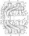
- Fig. 1 is a top plan view of a V-type combustion engine for use in an automotive vehicle according to a first preferred embodiment of the present invention;
- Fig. 2 is a front elevational view, with a portion cut away, of the V-type combustion engine of Fig. 1 as viewed from front of an automotive vehicle;
- Fig. 3 is a top plan view of a portion of the V-type combustion engine according to a second preferred embodiment of the present invention;
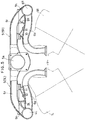
- Fig. 4 is a top plan view of the V-type combustion engine according to a third preferred embodiment of the present invention;
- Fig. 5 is a front elevational view, with a portion cut away, of the V-type combustion engine of Fig. 4 as viewed from front of the automotive vehicle;
- Fig. 6 is an elevational view, on an enlarged scale, showing a merging region of an upstream intake passage employed in the combustion engine of Fig. 4;
- Fig. 7 is a cross-sectional view taken along the line VII-VII in Fig. 6;
- Fig. 8 is an elevational view showing the merging region of the upstream intake passage employed in the combustion engine of Fig. 4; and
- Fig. 9 is a fragmentary elevational view of the merging region of the upstream intake passage in the combustion engine of Fig. 4 as viewed from rear of the automotive vehicle.
- In describing some preferred embodiments of the present invention, reference will be made to an 12-cylinder automobile internal combustion engine of a type comprising a cylinder block having two cylinder banks in a V-shaped configuration with in-line six cylinders in each bank.
- Referring first to Figs. 1 and 2 showing the first preferred embodiment of the present invention, an engine cylinder block is shown to have left-hand and right-
hand cylinder banks - The engine cylinder block has a
throttle casing 3 mounted thereon and positioned between the left-hand and right-hand cylinder banks throttle casing 3 has a hollow divided by a partition wall so as to define left-hand and right-hand throttle passages hand cylinder banks hand throttle passages - Positioned upward of the left-hand and right-
hand cylinder banks hand cylinder banks hand surge tanks surge tanks surge tanks throttle passages throttle casing 3 through an upstream intake passage means 5 as will be described subsequently in detail. - The upstream intake passage means 5 comprises a merging
region 5a extending a small distance from a rear end of thethrottle casing 3 in a direction parallel to the crank axis referred to above, and a pair ofbranch ducts region 5a so as to extend towards the left-hand and right-hand surge tanks region 5a is of a design progressively increasing in elevation so as to incline upwards in a direction close towards the rear of an automobile body structure at an angle of inclination generally conforming to the angle of inclination of a hingedly supported bonnet or hood adapted to selectively close and open an access opening leading to an engine room in the automobile body structure. An open end of the left-hand branch duct 5L remote from thethrottle casing 3 is fluid-connected with that portion of the upper sidewall of the left-hand surge tank 4L which is generally intermediate of the length of such left-hand surge tank 4L, whereas an open end of the right-hand branch duct 5R remote from thethrottle casing 3 is fluid-connected with that portion of the upper sidewall of the right-hand surge tank 4R which is generally intermediate of the length of such right-hand surge tank 4R. Respective connections between thebranch ducts surge tanks - The merging
region 5a of the upstream intake passage means 5 has apartition wall 5b dividing the interior thereof into left-hand and right-hand intake passageways 5c and 5d which are in communication with the left-hand and right-hand throttle passages throttle casing 3, respectively. Similarly, each of thebranch ducts intake passages partition wall 5e extending from one end of therespective branch duct surge tank merging region 5a. - The left-
hand surge tank 4L and theintake ports passages hand surge tank 4L confronting the longitudinal center space V to therespective intake ports 2a to 2f, having passed underneath the upstream intake passage means 5, specifically the left-hand branch duct 5L. Similarly, the right-hand surge tank 4R and theintake ports 2g to 21 in the right-hand cylinder bank 1R are communicated with each other through individual connectingpassages hand surge tank 4R confronting the longitudinal center space V to therespective intake ports 2g to 2l, having passed underneath the upstream intake passage means 5, specifically the right-hand branch duct 5R. - Two of the individual connecting
passages 6a to 6f which are positioned adjacent the left-hand branch duct 5L, that is, the connectingpassages surge tank 4L, while two of the individual connectingpassages 6g to 61 which are positioned adjacent the right-hand branch duct 5R, that is, the individual connectingpassages surge tank 4R. On the other hand, the remaining four connectingpassages hand branch duct 5L have their end portions adjacent the associatedsurge tank 4L defined by a common suction piping, while the remaining four connectingpassages hand branch duct 5R have their end portions adjacent the associatedsurge tank 4R defined by a common suction piping. - In other words, the
intake passages surge tank 4L a common piping portion that is divided by apartition wall 7 into two passage portions which form respective parts of theconnecting passages passage surge tank 4L a common piping portion that is divided by apartition wall 7 into two passage portions which form respective parts of theconnecting passages passages surge tank 4R a common piping portion that is divided by apartition wall 7 into two passage portions which form respective parts of theconnecting passages connecting passages 6l and 6k are in practice defined in a generally Y-shaped piping which comprises adjacent thesurge tank 4R a common piping portion that is divided by apartition wall 7 into two passage portions which form respective parts of theconnecting passages 6l and 6k. By the employment of this design, an access toignition plugs 8 associated with the left-hand and right-hand cylinder banks passages 6a to 6l. - A generally elongated connecting
tank 9L is mounted above the left-hand cylinder bank 1L so as to extend generally parallel to theadjacent surge tank 4L in a space delimited between thebranch duct 5L and a left-hand group of theconnecting passages 6a to 6f. As best shown in Fig. 2, this connectingtank 9L is communicated with theconnecting passages 6a to 6f of the left-hand group through respective short connectingpassageways 10, each having arespective shutter valve 11 pivotally supported therein by means of a common pivot shaft 12 that extends generally over the length of the connectingtank 9L. Similarly, a generally elongated connectingtank 9R is mounted above the right-hand cylinder bank lR so as to extend generally parallel to theadjacent surge tank 4R in a space delimited between thebranch duct 5R and a right-hand group of theconnecting passages 6g to 6l, and is communicated with theconnecting passages 6g to 6l through respective short connectingpassageways 10, each having arespective shutter valve 11 pivotally supported by means of a common pivot shaft 12 which extends generally over the length of the connectingtank 9R. As will be discussed later, thoseshutter valves 11 are adapted to open and dose the corresponding passage in accordance with the number of engine revolutions for the synchronism with an inertia supercharging. - Each of the
connecting tanks branch duct tank branch duct associated branch duct tank branch duct - Each of the left-hand and right-
hand surge tanks choke valve 13 disposed therein at a location substantially intermediate of the length thereof for pivotal movement between opened and closed position. Eachchoke valve 13 is operable to open and close the corresponding passage in accordance with the number of engine revolution for the synchronization with a resonant supercharging and, when held in the closed position, divides the interior of theassociated surge tank respective choke valve 13 is in the opened position, only one chamber is defined within the associatedsurge tank - More specifically, referring to the left-
hand surge tank 4L for the purpose of clarity, the connectingpassages 6a to 6f are communicated with each other through the single chamber in thesurge tank 4L when and so long as thechoke valve 13 is in the opened position, but when thechoke valve 13 is pivoted to the closed position, the interior of thesurge tank 4L is divided into twochambers chamber 4a being communicated with the connectingpassages 6a to 6c, while thechamber 4b is communicated with the connectingpassages 6d to 6f. On the other hand, the twointake passages hand branch duct 5L open into the interior of the associatedsurge tank 4L at respective locations each on one side of thechoke valve 13 and, therefore, when thechoke valve 13 is in the closed position dividing the interior of thesurge tank 4L into thechambers intake passages branch duct 5L is supplied into thechambers - A similar description made to the left-
hand surge tank 4L can equally apply to the right-hand surge tank 4R. Briefly speaking, when and so long as thechoke valve 13 in the right-hand surge tank 4R is in the closed position, air to be mixed with fuel which is then flowing through theintake passages hand branch duct 5R is supplied into thechambers hand surge tank 4R. - Assuming that the
choke valve 13 in each of the left-hand and right-hand surge tanks chambers respective surge tank means 14 having achoke valve 15 disposed therein at a location substantially intermediate of the length thereof and adapted to open or dose the corresponding connecting means in accordance with the number of engine revolution for the synchronization with a resonant supercharging. The respective connectingmeans 14 has a length chosen to be smaller than the length of thepartition wall 5e formed within the associatedbranch duct intake passages - It is to be noted that the
throttle casing 3 is rigidly mounted onstays 16 which are integrally formed with respective walls of the connectingpassages reference numeral 17 employed in Fig. 2 represent fuel injection nozzles through which fuel is injected into the associated combustion cylinders or chambers. - Dynamic effects of intake air brought about by the operation of the
valves passages 6a to 6c will not be fired immediately one after another; the combustion chambers communicated respectively with the connectingpassages 6d to 6f will not be fired immediately one after another; the combustion chambers communicated respectively with the connectingpassages 6g to 6i will not be fired immediately one after another; and the combustion chambers communicated respectively with the connectingpassages 6j to 6l will not be fired immediately one after another. - (1) When the number of revolutions of the combustion engine is lower than 3,500 rpm, all of the
valves branch ducts partition walls 5e being utilized as pressure reversing portions (i.e., a resonant supercharging takes place with theintake passages - (2) When the number of revolutions of the combustion engine is within the range of 3,500 to 4,500 rpm, the
valves valves 15 are opened and, therefore, the resonant supercharging takes place with the connecting means 14 utilized as resonant passages. - (3) When the number of revolutions of the combustion engine is within the range of 4,500 to 5,500 rpm, only the
valves 11 are closed and thevalves surge tanks - (4) When the number of revolutions of the combustion engine is higher than 5,500 rpm, all of the
valves - In this condition, the intake air sucked externally from a source thereof, for example, the atmosphere is, when entering the
throttle casing 3 and then the mergingregion 5a of the upstream intake passage means 5, divided equally into two equal air components which subsequently flow into the left-hand and right-hand intake passageways 5c and 5d. Each of the air components flowing respectively in the left-hand and right-hand intake passageways 5c and 5d is again divided into equal components within the associatedbranch duct partition wall 5e extending in a direction generally perpendicular to the crank axis, one flowing through theintake passage 5g and the other through theintake passage 5f. - Referring now to Fig. 3, there is shown the air intake system according to a second preferred embodiment of the present invention. It is however to be noted that, although Fig. 3 shows only the right-hand bank of the engine cylinder block for the sake of brevity, the left-hand bank of the same engine cylinder block is to be understood as constructed in a fashion similar to the right-hand bank, as illustrated hereinabove.
- According to the second preferred embodiment of the present invention, of the connecting
passages 6g to 6l, the connectingpassages 6g and 6l which are positioned at outermost of the other connecting passages with respect to the direction parallel to the crank axis, i.e., adjacent the front and rear end of the engine cylinder block, are each defined by an individual suction piping. On the other hand, the connectingpassages hand branch duct 5R have their ends adjacent the right-hand surge tank 4R which are defined by a common suction piping. - In other words, according to the embodiment shown in Fig. 3, the respective ends of the connecting
passages surge tank 4R are defined by a common suction piping having apartition wall 7 formed therein so as to define respective parts of the connectingpassages passages surge tank 4R are defined in a common suction piping having apartition wall 7 formed therein so as to define respective parts of the connectingpassages - The design according to the second embodiment shown in Fig. 3 permits the space between each neighboring
shutter valves 11 to increase as it approaches each of the opposite ends of the engine cylinder block in a direction generally parallel to the crank axis so that not only is it be possible to employ the connectingpassages 6g to 6l of equal length, but a convenient servicing of each bf the ignition plugs 8 can also be attained. - A third preferred embodiment of the present invention is shown in Figs. 4 to 9, reference to which will now be made for the detailed discussion thereof. According to the third embodiment of the present invention, the merging
region 5a of the upstream intake passage means 5 is positioned within the generally V-shaped longitudinal center space V between the left-hand and right-hand banks region 5a in any one of the first and second embodiments of the present invention as previously discussed, the mergingregion 5a in the third preferred embodiment of the present invention is comprised by a single passage element with no partition wall (corresponding to thepartition wall 5b in the previously discussed embodiments) formed therein. Similarly, thethrottle casing 3 employed in the third preferred embodiment of the present invention has only one throttle passage defined therein in communication with the mergingregion 5a. - As best shown in Fig. 4, the upstream intake passage means 5 is of a design wherein, after each of the left-hand and right-
hand branch ducts region 5a towards the associatedsurge tank respective branch duct rear intake passages front intake passage 5f being communicated with a front end portion of the associatedsurge tank rear intake passage 5g is communicated with a rear end portion of the associatedsurge tank surge tank connection 5h between thefront intake passage 5f and the front end portion of the associatedsurge tank surge tank connection 5i between therear intake passage 5f and the rear end portion of the associatedsurge tank surge tank - With respect to valves which serve to substantially vary the length of the intake pipings, the third embodiment of the present invention employs only the
shutter valves 11 and no valves equivalent to thevalves shutter valves 11 employed in the third embodiment of the present invention are adapted to be selectively closed and opened by respective actuators which are generally identified by 20 and which are not discussed in the description of any one of the first and second preferred embodiments of the present invention. - The connecting
passages 6a to 6l associated with the left-hand and right-hand cylinder banks - Figs. 6 to 9 illustrate the details of the merging
region 5a defined in the upstream intake passage means 5. The illustratedmerging region 5a is formed with an exhaust gas recirculating (EGR)passage 21 and a blow-bygas recirculating passage 22 and also with a bypass passage (ISC passage) 23 bypassing thethrottle valve 3a within thethrottle casing 3. - The details of the exhaust
gas recirculating passage 21 will now be discussed. A rear open end of the mergingregion 5a is, as dest shown in Figs. 6 and 7, provided with anEGR regulating valve 24 for regulating the quantity of exhaust gases being recirculated from an automobile exhaust system through the exhaustgas recirculating passage 21. For supporting theEGR regulating valve 24, the mergingregion 5a has a lower end formed with aflanged seat 25 to which theEGR regulating valve 24 is fitted as best shown in Fig. 9. The exhaust gases drawn from the automobile exhaust system are recirculated through an external piping (not shown) and then into a valve casing for theEGR regulating valve 24 through aninlet port 21a, entering the mergingregion 5a after having travelled past theEGR regulating valve 24. The exhaust gases so recirculated emerge outwardly from the mergingregion 5a through adischarge port 21b defined at a substantially central area of the mergingregion 5a. - The blow-by
gas recirculating passage 22 has adischarge opening 22a positioned immediately above thedischarge port 21b for the recirculated exhaust gases as best shown in Fig. 8. - As best shown in Fig. 9, the bypass or
ISC passage 23 extends from the passage within thethrottle casing 3 and then through a passage within the mergingregion 5a to anoutlet port 23a defined at a rear portion of the mergingregion 5a. Theoutlet port 23a of thebypass passage 23 is in turn communicated with aninlet port 23b, defined at a rear portion of the mergingregion 5a through an external piping (not shown) so that ISC air can flow from theoutlet port 23a and then into the mergingregion 5a through theinlet port 23b. It is to be noted that, although not shown, the external passage communicating between theoutlet port 23a and theinlet port 23b has an ISC valve disposed therein for regulating the flow of the ISC air to be subsequently discharged into the mergingregion 5a. - As best shown in Fig. 7, the merging
region 5a has an upper portion formed with afitting seat 27 to which acold injector 26 is fitted. - Although the present invention has been fully described in connection with the preferred embodiments thereof with reference to the accompanying drawings which are used only for the purpose of illustration, those skilled in the art will readily conceive numerous changes and modifications within the framework of obviousness upon the reading of the specification herein presented of the present invention.
Claims (21)
- A combustion engine of a type having first and second cylinder banks (1L; 1R) arranged in a generally V-shaped configuration and defining a center space (V) therebetween, said combustion engine having a crank axis along which a crank shaft extends, having a plurality of combustion cylinders which are defined in the first and second cylinder banks (1L; 1R) and spaced apart from each other in a direction generally parallel to the crank axis of the crank shaft, and having an air intake system comprising:a throttle casing (3) through which air is sucked in a direction substantially parallel to the crank axis;generally elongated first and second surge tanks (4L;4R) extending in a direction generally parallel to the crank axis and disposed on respective sides of the center space (V), one (4L) of the surge tanks (4L;4R) communicating through first connecting passages (6a-6f) with the combustion cylinders in the first cylinder bank (1L) and the other (4R) of the surge tanks (4L;4R) communicating through second connecting passages (6g-61) with the combustion cylinders in the second cylinder bank (1R);an upstream intake passage means (5) communicating the throttle casing (3) to each of the first and second surge tanks (4L;4R);said upstream intake passage means (5) comprising a merging region (5a) communicated with the throttle casing (3); andfirst and second branch ducts (5L;5R) branched off from the end of the merging region (5a) opposite the throttle casing (3), each of said first and second branch ducts (5L;5R) comprising two independent intake passages (5f,5g) leading, via a connection (5h,5i) each, into the first and second surge tanks (4L;4R), respectively, which connections (5h,5i) are spaced from each other in a direction parallel to the crank axis,characterized in thatsaid throttle casing (3) is disposed above the V-shaped longitudinal center space delimited between the cylinder banks (1L;1R) and between end portions of each of the first and second cylinder banks (1L; 1R);said connections (5h,5i) are formed on one sidewall of the associated surge tank (4L;4R) only; andgenerally elongated first and second connecting tanks (9L;9R) extending in a direction generally parallel to the crank axis are disposed in the vicinity of the first and second connecting passages (6a-6f; 6g-6l), said first connecting passages (6a-6f) and the first connecting tank (9L) being communicated with each other through first connecting passageways (10), while said second connecting passages (6g-6l) and the second connecting tank (9R) are communicated with each other through second connecting passageways (10), each of said first and second connecting passageways (10) having a shutter valve (11) disposed therein for selectively opening and closing the associated passageway (10).
- The combustion engine as claimed in claim 1, characterized in that said different connections (5h,5i) of each of the first and second surge tanks (4L;4R) are defined at respective positions generally intermediate of the length of the associated surge tank.
- The combustion engine as claimed in claim 1, characterized in that each of said different connections (5h,5i) of each of the first and second surge tanks (4L;4R) is defined at a position intermediate the length of one of approximately equal halves of the associated surge tank with respect to the direction parallel to the crank axis.
- The combustion engine as claimed in claim 1, characterized in that said throttle casing (3) has defined therein a pair of throttle passages (3a,3b) extending in a direction generally parallel to the crank axis and associated with the first and second cylinder banks, respectively, and in that said merging region (5a) has a hollow thereof divided by partition wall (5b) into two passages (5c,5d) through which the throttle passages (3a,3b) are communicated, respectively, with the first and second branch ducts (5L,5R).
- The combustion engine as claimed in claim 1, characterized in that said throttle casing (3) has a single passage extending in a direction generally parallel to the crank axis, and in that said merging region (5a) serves as a common passage from which the first and second branch ducts (5L;5R) are branched off.
- The combustion engine as claimed in claim 1, characterized in that a first opening/closing valve (13) for dynamic suction effect is disposed for each of the first and second cylinder banks (1L; 1R) within the surge tanks (4L;4R) at a position generally intermediate thereof with respect to the direction parallel to the crank axis, said first opening/closing valve (13) being operable to define within the associated surge tank (4L;4R) a single chamber when opended, and two chambers (4a,4b) when closed, said two chambers (4a,4b) being communicated with groups of combustion cylinders (2a-2c, 2g-2i, 2d-2f, 2j-2l), which are spaced from each other in terms of a firing sequence.
- The combustion engine as claimed in claim 6, characterized in that a first fluid-connecting means (14) is provided in each of the first and second surge tanks (4L;4R) for fluid-connecting the two chambers (4a,4b) together, and a second opening/closing valve (15) is disposed within the first fluid-connecting means (14) at a location generally intermediate of the length thereof.
- The combustion engine as claimed in claim 1, characterized in that the shutter valves (11) in the first connecting passageways (10) are supported on a common operating shaft (12L) and the shutter valves (11) in the second connecting passageways (10) are also supported on a common operating shaft (12R).
- The combustion engine as claimed in claim 1, characterized in that each of the first and second branch ducts (5L;5R) is positioned on top of the associated one of first and second connecting passages (6a-6f; 6g-6l) delimiting a space therebetween, in which the associated one of the first and second connecting tanks (9L;9R) is positioned.
- The combustion engine as claimed in claim 9, characterized in that an intermediate portion of each of the first and second connecting tanks (9L,9R) which is positioned in the immediate vicinity of the associated branch duct (5L;5R) is flattened in comparison to the remaining portion thereof.
- The combustion engine as claimed in claim 1, charcterized in that a suction piping means forming each of the first and second connecting passages (6a-6f; 6g-6l) comprises individual suction pipings (6c,6d; 6i,6j-Fig. 1, 4; 6g,6l-Fig. 3) and a common suction piping having a partition wall (7) dividing a hollow of the common suction piping into two adjoining individual suction passages (6a,6b,6e,6f; 6g,6h,6k,6l-Fig. 1, 4; 6h,6i,6j,6k-Fig. 3), said individual suction pipings and said common suction piping defining an access gap for the access to ignition plugs during servicing thereof.
- The combustion engine as claimed in claim 1, characterized in that all of the first and second connecting passages (6a-6f; 6g-6l) associated with the first and second cylinder banks, respectively, have a substantially equal length.
- An automotive car body structure, comprising a combustion engine as defined in anyone of claims 1 to 12,
characterized in
that the engine crank axis is aligned with a longitudinal sense of said body structure. - The automotive car body structure as claimed in claim 13, characterized in that the throttle casing (3) is mounted on the combustion engine at a position between the first and second cylinder banks (1L; 1R) and adjacent a front end thereof with respect to the longitudinal sense of the automotive body structure.
- The automotive car body structure as claimed in claim 14, characterized in that the merging region (5a) extends from the throttle casing (3) in a direction towards the end opposite the front end of the first and second cylinder banks (1L;1R), and in that each of said first and second branch ducts (5L;5R) extends in a direction generally transverse of the crank axis and the different connections (5h,5i) of each of the first and second surge tanks (4L;4R) are located at a position intermediate of the length of the associated surge tank (4L;4R).
- The automotive car body structure as claimed in claim 15, characterized in that each of the first and second branch ducts (5L;5R) has a partition wall (5e) extending in a direction generally perpendicular to the crank axis and also extending from the associated surge tank (4L;4R) so as to terminate in the vicinity of and spaced a slight distance inwardly from the merging region (5a), said partition wall dividing a portion of an interior of the associated branch duct (5L;5R) into two independent passages (5f,5g).
- The automotive car body structure as claimed in claim 15, characterized in that the different connections (5h,5i) are defined on the uppermost sidewall of each of the first and second surge tanks (4L;4R).
- The automotive car body structure as claimed in claim 13, characterized in that the merging region (5a) is disposed between the first and second cylinder banks (1L;1R) at a position adjacent their ends opposite their front ends, and the throttle casing (3) is disposed frontwardly of the merging region (5a).
- The automotive car body structure as claimed in claim 18, characterized in that each of said different connections (5h,5i) of each of the first and second surge tanks (4L;4R) is defined at a position intermediate the length of one of equal halves of the associated surge tank with respect to the direction parallel to the crank axis.
- The automotive car body structure as claimed in claim 19, characterized in that the different connections (5h,5i) are defined on the uppermost sidewall of each of the first and second surge tanks (4L;4R).
- The combustion engine as claimed in claim 1, characterized in that the combustion engine is a 12-cylinder combustion engine with six combustion cylinders defined in each of the first and second cylinder banks (1L;1R) in an in-line fashion.
Applications Claiming Priority (4)
| Application Number | Priority Date | Filing Date | Title |
|---|---|---|---|
| JP85810/90 | 1990-03-31 | ||
| JP8581090 | 1990-03-31 | ||
| JP2334056A JP2858706B2 (en) | 1990-03-31 | 1990-11-30 | V-type engine intake system |
| JP334056/90 | 1990-11-30 |
Publications (2)
| Publication Number | Publication Date |
|---|---|
| EP0450530A1 EP0450530A1 (en) | 1991-10-09 |
| EP0450530B1 true EP0450530B1 (en) | 1996-06-05 |
Family
ID=26426818
Family Applications (1)
| Application Number | Title | Priority Date | Filing Date |
|---|---|---|---|
| EP91105073A Expired - Lifetime EP0450530B1 (en) | 1990-03-31 | 1991-03-28 | Fuel intake system for V-type combustion engine |
Country Status (5)
| Country | Link |
|---|---|
| US (1) | US5081962A (en) |
| EP (1) | EP0450530B1 (en) |
| JP (1) | JP2858706B2 (en) |
| KR (1) | KR940001353B1 (en) |
| DE (1) | DE69119965T2 (en) |
Cited By (1)
| Publication number | Priority date | Publication date | Assignee | Title |
|---|---|---|---|---|
| AT414266B (en) * | 2003-12-11 | 2006-10-15 | Avl List Gmbh | INTAKE SYSTEM FOR A COMBUSTION ENGINE |
Families Citing this family (20)
| Publication number | Priority date | Publication date | Assignee | Title |
|---|---|---|---|---|
| US5168838A (en) * | 1990-10-29 | 1992-12-08 | Mazda Motor Corporation | Engine induction system |
| GB9113615D0 (en) * | 1991-06-24 | 1991-08-14 | Lotus Car | Multi-cylinder internal combustion engine intake manifold |
| JP3227854B2 (en) * | 1992-12-28 | 2001-11-12 | スズキ株式会社 | Engine intake system |
| DE19546643B4 (en) * | 1994-12-23 | 2006-02-09 | Volkswagen Ag | Air intake system for a multi-cylinder reciprocating internal combustion engine |
| JP3210825B2 (en) * | 1995-01-14 | 2001-09-25 | ヤマハ発動機株式会社 | V-type multi-cylinder engine intake system |
| US5632239A (en) * | 1996-04-16 | 1997-05-27 | Chrysler Corporation | Method of distributing air in an engine intake manifold |
| US5823156A (en) * | 1997-04-09 | 1998-10-20 | Kohler Co. | Dual bore intake manifold |
| DE19803804A1 (en) | 1998-01-31 | 1999-08-05 | Volkswagen Ag | Suction system for supplying combustion air to an internal combustion engine |
| DE19951582A1 (en) * | 1999-10-27 | 2001-05-03 | Bosch Gmbh Robert | Method and device for synchronizing at least two power control elements of an internal combustion engine |
| IT1319919B1 (en) | 2000-02-25 | 2003-11-12 | Iveco Fiat | INTAKE MANIFOLD FOR AN ENDOTHERMAL ENGINE. |
| JP2001295653A (en) * | 2000-04-17 | 2001-10-26 | Yamaha Motor Co Ltd | Intake control device for V-type multi-cylinder engine |
| US7275511B1 (en) * | 2006-07-26 | 2007-10-02 | Gm Global Technology Operations, Inc. | Intake manifold assembly |
| KR100774348B1 (en) * | 2006-12-07 | 2007-11-07 | 현대자동차주식회사 | 3-Plenum Type Variable Intake Manifold |
| DE102009053433A1 (en) * | 2009-11-17 | 2011-05-19 | Daimler Ag | Suction tube section and suction system |
| US8759049B2 (en) | 2010-02-25 | 2014-06-24 | Iogen Energy Corporation | Method for the production of a fermentation product from a sugar hydrolysate |
| CN103080306B (en) | 2010-08-20 | 2015-02-18 | 科德克希思公司 | Application of Glycoside Hydrolase 61 Family Protein in Cellulose Processing |
| US8709770B2 (en) | 2010-08-31 | 2014-04-29 | Iogen Energy Corporation | Process for improving the hydrolysis of cellulose in high consistency systems using one or more unmixed and mixed hydrolysis reactors |
| DK2748317T3 (en) | 2011-08-22 | 2017-07-17 | Codexis Inc | GH61 glycoside hydrolase protein variants and cofactors that enhance GH61 activity |
| US9366203B2 (en) * | 2013-09-24 | 2016-06-14 | Fca Us Llc | Conformable high pressure gaseous fuel storage system having a gas storage vessel with fractal geometry |
| US20150299739A1 (en) | 2014-04-17 | 2015-10-22 | Shell Oil Company | Processes for producing fermentation products |
Family Cites Families (19)
| Publication number | Priority date | Publication date | Assignee | Title |
|---|---|---|---|---|
| US3303832A (en) * | 1967-02-14 | High output engines | ||
| US2916027A (en) * | 1956-12-28 | 1959-12-08 | Gen Motors Corp | Charge forming means |
| JPS57148023A (en) * | 1981-03-11 | 1982-09-13 | Hino Motors Ltd | Intake or exhaust device for diesel engine |
| DE3561900D1 (en) * | 1984-03-10 | 1988-04-21 | Porsche Ag | Air inlet pipe arrangement for a multicylinder internal combustion engine |
| US4679531A (en) * | 1984-11-08 | 1987-07-14 | Mazda Motor Corporation | Intake system for internal combustion engine |
| JPS61116020A (en) * | 1984-11-08 | 1986-06-03 | Mazda Motor Corp | Engine intake-air device |
| JPH0730698B2 (en) * | 1985-08-28 | 1995-04-10 | マツダ株式会社 | Multi-cylinder engine intake system |
| JPS6270653A (en) * | 1985-09-24 | 1987-04-01 | Yamaha Motor Co Ltd | Exhaust gas purifying device for v-type engine |
| KR900000143B1 (en) * | 1985-10-04 | 1990-01-20 | 마쯔다 가부시기가이샤 | Induction system for v-type internal combustion engine |
| US4803961A (en) * | 1985-11-19 | 1989-02-14 | Mazda Motor Corporation | Air suction devices for multicylinder engines |
| JPH0742861B2 (en) * | 1986-03-10 | 1995-05-15 | ヤマハ発動機株式会社 | Internal combustion engine intake system |
| JP2543537B2 (en) * | 1986-10-30 | 1996-10-16 | マツダ株式会社 | Intake device for V-type multi-cylinder engine |
| JPS6423231A (en) * | 1987-07-20 | 1989-01-25 | Fuji Photo Film Co Ltd | Optical deflecting device |
| JP2583526B2 (en) * | 1987-10-01 | 1997-02-19 | マツダ株式会社 | Engine intake system |
| US4957071A (en) * | 1988-07-26 | 1990-09-18 | Nissan Motor Co., Ltd. | Intake system for V-type internal combustion engine |
| US4977865A (en) * | 1988-10-19 | 1990-12-18 | Mazda Motor Corporation | Intake system for V-type engine |
| JPH06105042B2 (en) * | 1989-06-30 | 1994-12-21 | マツダ株式会社 | Engine intake system |
| US5027769A (en) * | 1989-08-25 | 1991-07-02 | Mitsubishi Jidosha Kogya Kabushiki Kaisha | Throttle valve control apparatus |
| US5010854A (en) * | 1990-07-12 | 1991-04-30 | Nissan Motor Co., Ltd. | Intake apparatus for V-type 8-cyl internal combustion engine |
-
1990
- 1990-11-30 JP JP2334056A patent/JP2858706B2/en not_active Expired - Lifetime
-
1991
- 1991-03-28 EP EP91105073A patent/EP0450530B1/en not_active Expired - Lifetime
- 1991-03-28 KR KR1019910004876A patent/KR940001353B1/en not_active Expired - Fee Related
- 1991-03-28 DE DE69119965T patent/DE69119965T2/en not_active Expired - Fee Related
- 1991-03-29 US US07/677,566 patent/US5081962A/en not_active Expired - Fee Related
Cited By (1)
| Publication number | Priority date | Publication date | Assignee | Title |
|---|---|---|---|---|
| AT414266B (en) * | 2003-12-11 | 2006-10-15 | Avl List Gmbh | INTAKE SYSTEM FOR A COMBUSTION ENGINE |
Also Published As
| Publication number | Publication date |
|---|---|
| EP0450530A1 (en) | 1991-10-09 |
| DE69119965D1 (en) | 1996-07-11 |
| JPH03286174A (en) | 1991-12-17 |
| KR910017060A (en) | 1991-11-05 |
| DE69119965T2 (en) | 1996-10-24 |
| US5081962A (en) | 1992-01-21 |
| KR940001353B1 (en) | 1994-02-19 |
| JP2858706B2 (en) | 1999-02-17 |
Similar Documents
| Publication | Publication Date | Title |
|---|---|---|
| US5081962A (en) | Fuel intake system for v-type combustion engine | |
| US4957071A (en) | Intake system for V-type internal combustion engine | |
| JP3353191B2 (en) | Multi-cylinder V-type engine | |
| JPH0578650B2 (en) | ||
| US4867109A (en) | Intake passage arrangement for internal combustion engines | |
| US5630386A (en) | Intake structure for V-type engine | |
| US5123382A (en) | Intake system for a combustion engine | |
| US5787851A (en) | Intake control system | |
| US6408809B2 (en) | Intake control device for multi-cylinder V-type engine | |
| US5105774A (en) | Intake system for multicylinder internal combustion engines for motor vehicles | |
| EP0551209B1 (en) | Induction systems for internal combustion engines | |
| KR960012380B1 (en) | Variable intake of internal combustion engine | |
| US5322038A (en) | Suction system for internal combustion engine | |
| WO1993000505A2 (en) | Intake manifold for a multi-cylinder internal combustion engine | |
| US5711261A (en) | Intake system for V-type engine | |
| JPH02221633A (en) | Air intake device of vehicle engine | |
| US7444974B2 (en) | Internal combustion engine intake device | |
| JP4078816B2 (en) | Exhaust gas recirculation device for V-type engine | |
| JPH03271558A (en) | Intake device of multiplecylinder v-engine | |
| JP2000220540A (en) | Intake manifold structure | |
| JP2021080911A (en) | engine | |
| US11982251B2 (en) | Air supply device with intake pipes that overlap in an air chamber, internal combustion engine with an air supply device, and motor vehicle | |
| GB2046357A (en) | An induction system for an internal combustion engine | |
| JPH077528Y2 (en) | Cam cover device for V-type internal combustion engine | |
| JP2539840Y2 (en) | Intake device for internal combustion engine |
Legal Events
| Date | Code | Title | Description |
|---|---|---|---|
| PUAI | Public reference made under article 153(3) epc to a published international application that has entered the european phase |
Free format text: ORIGINAL CODE: 0009012 |
|
| AK | Designated contracting states |
Kind code of ref document: A1 Designated state(s): DE FR GB |
|
| 17P | Request for examination filed |
Effective date: 19920317 |
|
| 17Q | First examination report despatched |
Effective date: 19920611 |
|
| GRAH | Despatch of communication of intention to grant a patent |
Free format text: ORIGINAL CODE: EPIDOS IGRA |
|
| GRAA | (expected) grant |
Free format text: ORIGINAL CODE: 0009210 |
|
| AK | Designated contracting states |
Kind code of ref document: B1 Designated state(s): DE FR GB |
|
| REF | Corresponds to: |
Ref document number: 69119965 Country of ref document: DE Date of ref document: 19960711 |
|
| ET | Fr: translation filed | ||
| PLBE | No opposition filed within time limit |
Free format text: ORIGINAL CODE: 0009261 |
|
| STAA | Information on the status of an ep patent application or granted ep patent |
Free format text: STATUS: NO OPPOSITION FILED WITHIN TIME LIMIT |
|
| 26N | No opposition filed | ||
| PGFP | Annual fee paid to national office [announced via postgrant information from national office to epo] |
Ref country code: FR Payment date: 20000310 Year of fee payment: 10 |
|
| PGFP | Annual fee paid to national office [announced via postgrant information from national office to epo] |
Ref country code: GB Payment date: 20000322 Year of fee payment: 10 |
|
| PGFP | Annual fee paid to national office [announced via postgrant information from national office to epo] |
Ref country code: DE Payment date: 20000327 Year of fee payment: 10 |
|
| PG25 | Lapsed in a contracting state [announced via postgrant information from national office to epo] |
Ref country code: GB Free format text: LAPSE BECAUSE OF NON-PAYMENT OF DUE FEES Effective date: 20010328 |
|
| GBPC | Gb: european patent ceased through non-payment of renewal fee |
Effective date: 20010328 |
|
| PG25 | Lapsed in a contracting state [announced via postgrant information from national office to epo] |
Ref country code: FR Free format text: LAPSE BECAUSE OF NON-PAYMENT OF DUE FEES Effective date: 20011130 |
|
| REG | Reference to a national code |
Ref country code: FR Ref legal event code: ST |
|
| PG25 | Lapsed in a contracting state [announced via postgrant information from national office to epo] |
Ref country code: DE Free format text: LAPSE BECAUSE OF NON-PAYMENT OF DUE FEES Effective date: 20020101 |