EP0450509A1 - Internal combustion engine with at least an exhaust port in the cylinder - Google Patents
Internal combustion engine with at least an exhaust port in the cylinder Download PDFInfo
- Publication number
- EP0450509A1 EP0450509A1 EP91104967A EP91104967A EP0450509A1 EP 0450509 A1 EP0450509 A1 EP 0450509A1 EP 91104967 A EP91104967 A EP 91104967A EP 91104967 A EP91104967 A EP 91104967A EP 0450509 A1 EP0450509 A1 EP 0450509A1
- Authority
- EP
- European Patent Office
- Prior art keywords
- valve
- accordance
- engine
- closing
- cylinder
- Prior art date
- Legal status (The legal status is an assumption and is not a legal conclusion. Google has not performed a legal analysis and makes no representation as to the accuracy of the status listed.)
- Withdrawn
Links
- 238000002485 combustion reaction Methods 0.000 title claims abstract description 28
- 230000001105 regulatory effect Effects 0.000 claims abstract description 27
- 230000005540 biological transmission Effects 0.000 claims description 11
- 230000002000 scavenging effect Effects 0.000 claims description 8
- 238000002347 injection Methods 0.000 claims description 6
- 239000007924 injection Substances 0.000 claims description 6
- 235000001674 Agaricus brunnescens Nutrition 0.000 claims description 3
- 230000001276 controlling effect Effects 0.000 claims 5
- 239000007789 gas Substances 0.000 description 6
- 230000006835 compression Effects 0.000 description 4
- 238000007906 compression Methods 0.000 description 4
- 230000008030 elimination Effects 0.000 description 2
- 238000003379 elimination reaction Methods 0.000 description 2
- 239000000446 fuel Substances 0.000 description 2
- 230000033001 locomotion Effects 0.000 description 2
- 238000004519 manufacturing process Methods 0.000 description 2
- 239000000110 cooling liquid Substances 0.000 description 1
- 208000002925 dental caries Diseases 0.000 description 1
- 239000000243 solution Substances 0.000 description 1
- 230000000153 supplemental effect Effects 0.000 description 1
- 230000001360 synchronised effect Effects 0.000 description 1
Images


Classifications
-
- F—MECHANICAL ENGINEERING; LIGHTING; HEATING; WEAPONS; BLASTING
- F02—COMBUSTION ENGINES; HOT-GAS OR COMBUSTION-PRODUCT ENGINE PLANTS
- F02B—INTERNAL-COMBUSTION PISTON ENGINES; COMBUSTION ENGINES IN GENERAL
- F02B25/00—Engines characterised by using fresh charge for scavenging cylinders
- F02B25/02—Engines characterised by using fresh charge for scavenging cylinders using unidirectional scavenging
- F02B25/04—Engines having ports both in cylinder head and in cylinder wall near bottom of piston stroke
-
- F—MECHANICAL ENGINEERING; LIGHTING; HEATING; WEAPONS; BLASTING
- F02—COMBUSTION ENGINES; HOT-GAS OR COMBUSTION-PRODUCT ENGINE PLANTS
- F02B—INTERNAL-COMBUSTION PISTON ENGINES; COMBUSTION ENGINES IN GENERAL
- F02B29/00—Engines characterised by provision for charging or scavenging not provided for in groups F02B25/00, F02B27/00 or F02B33/00 - F02B39/00; Details thereof
-
- F—MECHANICAL ENGINEERING; LIGHTING; HEATING; WEAPONS; BLASTING
- F02—COMBUSTION ENGINES; HOT-GAS OR COMBUSTION-PRODUCT ENGINE PLANTS
- F02B—INTERNAL-COMBUSTION PISTON ENGINES; COMBUSTION ENGINES IN GENERAL
- F02B41/00—Engines characterised by special means for improving conversion of heat or pressure energy into mechanical power
-
- F—MECHANICAL ENGINEERING; LIGHTING; HEATING; WEAPONS; BLASTING
- F02—COMBUSTION ENGINES; HOT-GAS OR COMBUSTION-PRODUCT ENGINE PLANTS
- F02B—INTERNAL-COMBUSTION PISTON ENGINES; COMBUSTION ENGINES IN GENERAL
- F02B69/00—Internal-combustion engines convertible into other combustion-engine type, not provided for in F02B11/00; Internal-combustion engines of different types characterised by constructions facilitating use of same main engine-parts in different types
- F02B69/06—Internal-combustion engines convertible into other combustion-engine type, not provided for in F02B11/00; Internal-combustion engines of different types characterised by constructions facilitating use of same main engine-parts in different types for different cycles, e.g. convertible from two-stroke to four stroke
-
- F—MECHANICAL ENGINEERING; LIGHTING; HEATING; WEAPONS; BLASTING
- F02—COMBUSTION ENGINES; HOT-GAS OR COMBUSTION-PRODUCT ENGINE PLANTS
- F02F—CYLINDERS, PISTONS OR CASINGS, FOR COMBUSTION ENGINES; ARRANGEMENTS OF SEALINGS IN COMBUSTION ENGINES
- F02F1/00—Cylinders; Cylinder heads
- F02F1/24—Cylinder heads
- F02F1/42—Shape or arrangement of intake or exhaust channels in cylinder heads
- F02F1/4214—Shape or arrangement of intake or exhaust channels in cylinder heads specially adapted for four or more valves per cylinder
- F02F1/4221—Shape or arrangement of intake or exhaust channels in cylinder heads specially adapted for four or more valves per cylinder particularly for three or more inlet valves
-
- F—MECHANICAL ENGINEERING; LIGHTING; HEATING; WEAPONS; BLASTING
- F02—COMBUSTION ENGINES; HOT-GAS OR COMBUSTION-PRODUCT ENGINE PLANTS
- F02B—INTERNAL-COMBUSTION PISTON ENGINES; COMBUSTION ENGINES IN GENERAL
- F02B1/00—Engines characterised by fuel-air mixture compression
- F02B1/02—Engines characterised by fuel-air mixture compression with positive ignition
- F02B1/04—Engines characterised by fuel-air mixture compression with positive ignition with fuel-air mixture admission into cylinder
-
- F—MECHANICAL ENGINEERING; LIGHTING; HEATING; WEAPONS; BLASTING
- F02—COMBUSTION ENGINES; HOT-GAS OR COMBUSTION-PRODUCT ENGINE PLANTS
- F02B—INTERNAL-COMBUSTION PISTON ENGINES; COMBUSTION ENGINES IN GENERAL
- F02B75/00—Other engines
- F02B75/02—Engines characterised by their cycles, e.g. six-stroke
- F02B2075/022—Engines characterised by their cycles, e.g. six-stroke having less than six strokes per cycle
- F02B2075/025—Engines characterised by their cycles, e.g. six-stroke having less than six strokes per cycle two
-
- F—MECHANICAL ENGINEERING; LIGHTING; HEATING; WEAPONS; BLASTING
- F02—COMBUSTION ENGINES; HOT-GAS OR COMBUSTION-PRODUCT ENGINE PLANTS
- F02B—INTERNAL-COMBUSTION PISTON ENGINES; COMBUSTION ENGINES IN GENERAL
- F02B75/00—Other engines
- F02B75/02—Engines characterised by their cycles, e.g. six-stroke
- F02B2075/022—Engines characterised by their cycles, e.g. six-stroke having less than six strokes per cycle
- F02B2075/027—Engines characterised by their cycles, e.g. six-stroke having less than six strokes per cycle four
-
- F—MECHANICAL ENGINEERING; LIGHTING; HEATING; WEAPONS; BLASTING
- F02—COMBUSTION ENGINES; HOT-GAS OR COMBUSTION-PRODUCT ENGINE PLANTS
- F02B—INTERNAL-COMBUSTION PISTON ENGINES; COMBUSTION ENGINES IN GENERAL
- F02B2275/00—Other engines, components or details, not provided for in other groups of this subclass
- F02B2275/14—Direct injection into combustion chamber
-
- F—MECHANICAL ENGINEERING; LIGHTING; HEATING; WEAPONS; BLASTING
- F02—COMBUSTION ENGINES; HOT-GAS OR COMBUSTION-PRODUCT ENGINE PLANTS
- F02B—INTERNAL-COMBUSTION PISTON ENGINES; COMBUSTION ENGINES IN GENERAL
- F02B2275/00—Other engines, components or details, not provided for in other groups of this subclass
- F02B2275/18—DOHC [Double overhead camshaft]
-
- F—MECHANICAL ENGINEERING; LIGHTING; HEATING; WEAPONS; BLASTING
- F02—COMBUSTION ENGINES; HOT-GAS OR COMBUSTION-PRODUCT ENGINE PLANTS
- F02F—CYLINDERS, PISTONS OR CASINGS, FOR COMBUSTION ENGINES; ARRANGEMENTS OF SEALINGS IN COMBUSTION ENGINES
- F02F1/00—Cylinders; Cylinder heads
- F02F1/24—Cylinder heads
- F02F2001/244—Arrangement of valve stems in cylinder heads
- F02F2001/245—Arrangement of valve stems in cylinder heads the valve stems being orientated at an angle with the cylinder axis
-
- Y—GENERAL TAGGING OF NEW TECHNOLOGICAL DEVELOPMENTS; GENERAL TAGGING OF CROSS-SECTIONAL TECHNOLOGIES SPANNING OVER SEVERAL SECTIONS OF THE IPC; TECHNICAL SUBJECTS COVERED BY FORMER USPC CROSS-REFERENCE ART COLLECTIONS [XRACs] AND DIGESTS
- Y02—TECHNOLOGIES OR APPLICATIONS FOR MITIGATION OR ADAPTATION AGAINST CLIMATE CHANGE
- Y02T—CLIMATE CHANGE MITIGATION TECHNOLOGIES RELATED TO TRANSPORTATION
- Y02T10/00—Road transport of goods or passengers
- Y02T10/10—Internal combustion engine [ICE] based vehicles
- Y02T10/12—Improving ICE efficiencies
Definitions
- the present invention relates to a multivalve high performance internal combustion engine either four-stroke or two-stroke.
- the purpose of the present invention is to improve the efficiency and performance of said engines whether four- or two-stroke by increasing the cross section areas for passage of intake air and the compression ratio.
- the object of the present invention is a multivalve high performance internal combustion engine equipped with at least one cylinder and at least two intake ducts per cylinder in the head and regulated by respective intake valves and characterized in that it has at least one exhaust port per cylinder made in said cylinder, said exhaust port being regulated by valve means whose opening and closing are timed with the opening and closing of the aforementioned valves in accordance with a predetermined plan, or pattern, of operation.
- said engine has at least one exhaust duct per cylinder in the head and regulated by a respective exhaust valve and is characterized in that it is equipped with at least one exhaust port per cylinder made in said cylinder and regulated by valve means whose opening and closing are timed with the opening and closing of said valve in accordance with a predetermined plan, or pattern, of operation.
- Direct injection multivalve two-stroke engines have at least one cylinder and one air pump for scavenging and supply of air in the combustion chamber through at least one duct in the head and regulated by a respective valve and are characterized in that they have at least one exhaust port per cylinder made in said cylinder, said exhaust port being regulated by valve means whose opening and closing are timed with the opening and closing of said valve in accordance with a predetermined plan, or pattern, of operation.
- An important advantage of the present invention is the reduction in the four-stroke engine or elimination in the two-stroke engine of the number of exhaust valves located in the combustion chamber of said engine.
- the surface thereof is usable for mounting other intake valves which, arranged in opposing positions, create crossed flows and generate turbulences which improve combustion of the charge.
- valve or valves are connected to an intake air pump which ensures maximal filling of the cylinder and optimal unidirectional scavenging of the cylinder.
- Another advantage of the invention is the possibility of standardizing the architecture of the block for four-stroke and two-stroke engines with considerable economies in design, experimentation and production costs.
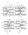
- FIG. 1 is a schematic cross section view of an internal combustion engine of the four-stroke type in which is shown the exhaust port in the cylinder.
- FIG. 2 is a schematic cross section view of the engine of FIG. 1 in which the exhaust ducts are connected together.
- FIGS. 3, 4, 5 and 6 are schematic cross sections showing the cylinder head of the four-stroke engine with some possible arrangements of the intake and exhaust valves with their associated ducts.
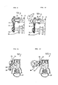
- FIGS. 7 and 8 are schematic cross sections of a two-stroke internal combustion engine with direct fuel injection and an air pump for scavenging and supply.
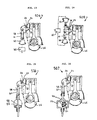
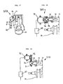
- FIGS. 9 to 19 show schematic drawings of control devices for the valve means which regulate the exhaust port in the cylinder.
- reference number 10 indicates the cylinder head of a four-stroke engine
- 11 indicates the cylinder
- 12 the exhaust duct in the head
- 13 indicates the associated exhaust valve with the valve seat
- 15 indicates the intake duct and 16 and 17 the respective valve and valve seat.
- 18 indicates the piston
- 19 the piston rod and 20 the cavities for the cooling liquid of the cylinder 11.
- the number 21 indicates the exhaust port in the cylinder 11 and 22 the exhaust duct wherein is arranged a rotating valve 23 provided with a cavity or passage 24 appropriately timed with the valves 13 and 16 in accordance with a predetermined plan, or pattern, of operation.
- the number 25 indicates the exhaust manifold of the duct 22 of FIG. 1 while in FIG. 2 reference number 26 indicates the exhaust manifold connecting the duct 12 of the head 10 to the duct 22 of the cylinder 11.
- Reference number 27 indicates the crown of the combustion chamber 28.
- FIGS. 3, 4, 5 and 6 are examples of possible preferred arrangements of the exhaust valves and ducts 12 and intake valves and ducts 15 in the head 10, the same numbers as in FIGS. 1 and 2 indicate the common parts, while 30 indicates the seat of the sparking plug (not shown) and the combustion chamber 28 is shown with broken lines.
- the engine shown in FIGS. 1-6 operates in accordance with the Otto four-stroke cycle, completing the usual stokes of charge intake, compression, ignition and combustion, expansion and exhaust of burnt gases.
- the exhaust valves 23 and 13 are appropriately timed together so as to be controlled to open simultaneously or one before the other, e.g. the valve 23 before the valve 13, so that in the final part of the exhaust phase only the valve 13 remains open while the exhaust port 21 is closed by the valve 23 and intercepted by the piston 18.
- the intake valves 16 are appropriately timed with the exhaust valves 13 and 23 so as to begin to open when the valve 13 is still open and to be completely open at the beginning of the intake stroke of the piston 18.
- the multivalve engine in accordance with the invention has combustion chambers 28 in the crown 27 of which are mounted two intake valves 16 and one exhaust valve 13 as shown in FIGS. 3 and 6 or three intake valves 16 and one exhaust valve 13 as shown in FIG. 4 or four intake valves 16 and one exhaust valve 3 as shown in FIG. 5.
- the intake ducts 15 can be single, as shown in FIGS. 3 and 5, or paired as in FIGS. 4 and 6.
- each cylinder has another exhaust port 21 in the cylinder 11, regulated by a rotating valve 23 as shown in FIGS. 1 and 2.
- the cross section area of the exhaust port 21 combines with the one uncovered by the exhaust valve 13 in the exhaust duct 12 of the head 10 to exhaust the burnt gases from the engine.
- the cross section area of said crown can be used to increase the overall passage cross section and also the number of intake valves, contributing to better filling and more efficient combustion of the engine.
- FIGS. 7 and 8 show schematically and in cross section a two-stroke internal combustion engine while the same numbers as in FIGS. 1 and 2 indicate common details and 40 indicates the head in which are made the intake ducts 41 regulated by the valves 42 with their respective valve seats 43.
- Number 44 indicates the camshaft and 45 the sparking plug, 46 indicates the fuel injector which injects directly into the cylinder 11 and the combustion chamber 28.
- Number 47 indicates generally an air pump connected to the intake manifold 48, 49 the opening for atmospheric air intake and 50 and 51 indicate the air passage between the air pump 47 and the intake manifold 48.
- the operating cycle of the internal combustion engine which is the object of the present invention is, as mentioned, the known four-stroke in one case and two-stroke with intake valve 42 in the second case.
- the rotating valve 23 can also be the sliding or mushroom type and regulates opening and closing of the port 21 in the cylinder 11 in a manner synchronized with opening and closing of the valves 42, or 13 and 16 arranged in the head 10 or 40.
- the position of the exhaust ports 21 along the generating line of the cylinders can be different from the one shown, e.g. closer to bottom dead centre of the piston.
- reference number 50 indicates as a whole a control device for the rotating valve 23 equipped with as many cavities or passages 24 as there are cylinders in the engine.
- the device 50 includes a toothed pulley 51 keyed on the shaft 52 integral with said rotating valve, a toothed belt 53 and toothed pulley 54 keyed on the crankshaft 55 of the engine shown in FIGS. 1-8 with the pulleys 51 and 54 appropriately timed.
- Motion transmission from the crankshaft 55 and the shaft 52 of the rotating valve 23 can be achieved as an alternative by means of a chain or gears.
- the reduction ration is selected on the basis of the type of operation desired for the rotating valve 23, e.g. it can be 1/2 or 1/4 for a four-stroke engine or 1 and 1/2 for a two-stroke engine.
- the rotating valve 23 is appropriately timed with the valves 13 and 16 in accordance with a predetermined plan or pattern of operation so as to open simultaneously with or in advance of the valves 13 and so that the valves 16 begin to open when the valve 13 is still open. Timing between the rotating valve 23 and the valve 42 can also be selected so that the latter begins to open when the rotating valve 23 is still open.
- FIG. 10 shows a variant of the device 50 of FIG. 9.
- the control device is indicated as a whole by 501 and comprises also a timing regulating device 56 which is operationally connected to the shaft 52 and the pulley 51 and is piloted by an electromagnetic actuator 57 of the on/off or proportional type, controlled by the control unit represented schematically by the block 65.
- the timing regulating device 56 permits regulation of the timing of the shaft 52 with the shaft 55 depending on the predetermined engine parameters, e.g. speed.
- opening of the rotating valve can be retarded while at high speeds it can be advanced.
- FIG. 11 shows schematically a valve 23 having through cavitys or passages 24 and driven to oscillate from a position in which it closes the exhaust port 21 to a position in which it opens said exhaust port, by means of a device 502 consisting of a rod 58 and a crank 59 entrained by the crankshaft 55 with predetermined transmission and timing ratio.
- 503 indicates as a whole a control device for the rotating valve 23 which is appropriately timed with the valves 13 and 16 and comprises a Malta cross mechanism operationally connected to the shaft 52 of the rotating valve 23 and to the crankshaft 66 which is driven with a suitable transmission ratio by the drive shaft 55.
- valve 23 is driven to oscillate by a device 504 consisting of a rod 58 driven by the coil of an electromagnetic actuator 60 of the on/off or proportional type against the action of the spring 61, while in the variant of FIG. 14 it is driven to oscillate by a device 505 consisting of the rod 62 which is driven by two electromagnetic actuators 64 and 64 which are also of the on/off or proportional type and capable of pulling or pushing said rod.
- the electromagnetic actuators 60, 63, 64 are operationally connected to a control unit represented schematically by the block 65.
- valve 23 is driven to oscillate by a control device 506 consisting of a rod 58 and a frame 69 driven against the action of the spring 61 by a crank 68 operationally connected to the drive shaft 55 with a predetermined transmission and timing ratio.
- a control device 506 consisting of a rod 58 and a frame 69 driven against the action of the spring 61 by a crank 68 operationally connected to the drive shaft 55 with a predetermined transmission and timing ratio.
- valve 23 is driven to oscillate by a control device 507 consisting of a rod 58 and a frame 69 driven against the action of the spring 61 by a triangular eccentric 71 operationally connected to the drive shaft 55 with predetermined transmission and timing ratio.
- a control device 507 consisting of a rod 58 and a frame 69 driven against the action of the spring 61 by a triangular eccentric 71 operationally connected to the drive shaft 55 with predetermined transmission and timing ratio.
- reference number 508 indicates overall a control device for the rotating valve 23 comprising a rod 58 driven against the action of the spring 61 by a camshaft or eccentrics 72 operated by the drive shaft 55 with predetermined transmission and timing ratio.
- reference number 509 indicates overall a control device for the rotating valve 23 consisting of an angular electromagnetic actuator 72 which controls the shaft 52 of said valve through the frontal disks 73 and 74 and is operationally connected to the electronic control unit 65 to control opening and closing of the valve 23 in a manner timed with the opening and closing of said valves 16, 42 in accordance with a predetermined plan, or pattern, of operation.
- reference number 510 indicates overall a control device which constitutes a variant of the one in FIG. 18 in which the angular electromagnetic actuator 72 is operationally connected to the shaft 52 through a pulley 75, a toothed belt 76 and a pulley 51 and to a control unit represented schematically by the block 65.
- the shaft 52 can be driven by a chain or gear.
Landscapes
- Engineering & Computer Science (AREA)
- Chemical & Material Sciences (AREA)
- Combustion & Propulsion (AREA)
- Mechanical Engineering (AREA)
- General Engineering & Computer Science (AREA)
- Cylinder Crankcases Of Internal Combustion Engines (AREA)
- Combustion Methods Of Internal-Combustion Engines (AREA)
- Output Control And Ontrol Of Special Type Engine (AREA)
- Valve Device For Special Equipments (AREA)
- Valve-Gear Or Valve Arrangements (AREA)
Abstract
Multivalve high performance internal combustion engine with at least one cylinder, (11) intake and exhaust ducts (15;12) in the head regulated by respective valves (16;13) and in which said cylinder (11) has at least one exhaust port (21) regulated by valve means (23) timed with said valves (16;13) with a predetermined operating plan, or pattern.
Description
- The present invention relates to a multivalve high performance internal combustion engine either four-stroke or two-stroke.
- The use is known in high performance four-stroke internal combustion engines of feed and exhaust systems made in the cylinder head with an ever larger number of ducts regulated by their respective valves, with the purpose of obtaining good cylinder filling and rapid scavenging of burnt gases therefrom.
- In two-stroke engines the use is known of a plurality of exhaust and transfer ports in the wall of said cylinder to obtain in this case also efficient filling and rapid scavenging of the burnt gases from said cylinder.
- It is clear that the surface area of the combustion chamber crown in which are placed the intake and exhaust valve seats in the four-stroke engine is limited and hence the choice of several valves with a more or less small cross-section involve same problems. In the two-stroke engine also it is not possible to have broad surfaces on the cylinder wall to make many exhaust and transfer ports.
- In addition, due to purely geometric problems, a larger number of valves compromises the possibility of obtaining high compression ratios because of the large volume of the combustion chamber and the higher number of cavities in the piston head to provide the predetermined valve lift.
- The purpose of the present invention is to improve the efficiency and performance of said engines whether four- or two-stroke by increasing the cross section areas for passage of intake air and the compression ratio.
- The object of the present invention is a multivalve high performance internal combustion engine equipped with at least one cylinder and at least two intake ducts per cylinder in the head and regulated by respective intake valves and characterized in that it has at least one exhaust port per cylinder made in said cylinder, said exhaust port being regulated by valve means whose opening and closing are timed with the opening and closing of the aforementioned valves in accordance with a predetermined plan, or pattern, of operation.
- With multivalve four-stroke engines said engine has at least one exhaust duct per cylinder in the head and regulated by a respective exhaust valve and is characterized in that it is equipped with at least one exhaust port per cylinder made in said cylinder and regulated by valve means whose opening and closing are timed with the opening and closing of said valve in accordance with a predetermined plan, or pattern, of operation.
- Direct injection multivalve two-stroke engines have at least one cylinder and one air pump for scavenging and supply of air in the combustion chamber through at least one duct in the head and regulated by a respective valve and are characterized in that they have at least one exhaust port per cylinder made in said cylinder, said exhaust port being regulated by valve means whose opening and closing are timed with the opening and closing of said valve in accordance with a predetermined plan, or pattern, of operation.
- An important advantage of the present invention is the reduction in the four-stroke engine or elimination in the two-stroke engine of the number of exhaust valves located in the combustion chamber of said engine.
- With reduction or elimination of the exhaust valves from the combustion chamber crown, the surface thereof is usable for mounting other intake valves which, arranged in opposing positions, create crossed flows and generate turbulences which improve combustion of the charge.
- In the two-stroke engine version with direct injection the valve or valves are connected to an intake air pump which ensures maximal filling of the cylinder and optimal unidirectional scavenging of the cylinder.
- Another advantage of the invention is the possibility of standardizing the architecture of the block for four-stroke and two-stroke engines with considerable economies in design, experimentation and production costs.
- The characteristics and advantages of the present invention will now be described with reference to the annexed figures from 1 to 19 wherein are shown by way of nonlimiting examples some preferred embodiments of said invention.
- FIG. 1 is a schematic cross section view of an internal combustion engine of the four-stroke type in which is shown the exhaust port in the cylinder.
- FIG. 2 is a schematic cross section view of the engine of FIG. 1 in which the exhaust ducts are connected together.
- FIGS. 3, 4, 5 and 6 are schematic cross sections showing the cylinder head of the four-stroke engine with some possible arrangements of the intake and exhaust valves with their associated ducts.
- FIGS. 7 and 8 are schematic cross sections of a two-stroke internal combustion engine with direct fuel injection and an air pump for scavenging and supply.
- FIGS. 9 to 19 show schematic drawings of control devices for the valve means which regulate the exhaust port in the cylinder. In FIGS. 1 and 2
reference number 10 indicates the cylinder head of a four-stroke engine, 11 indicates the cylinder, 12 the exhaust duct in thehead valve seat cylinder cylinder 11. - The
number 21 indicates the exhaust port in thecylinder valve 23 provided with a cavity orpassage 24 appropriately timed with thevalves number 25 indicates the exhaust manifold of theduct 22 of FIG. 1 while in FIG. 2reference number 26 indicates the exhaust manifold connecting theduct 12 of thehead 10 to theduct 22 of thecylinder 11.Reference number 27 indicates the crown of thecombustion chamber 28. - FIGS. 3, 4, 5 and 6 are examples of possible preferred arrangements of the exhaust valves and
ducts 12 and intake valves andducts 15 in thehead 10, the same numbers as in FIGS. 1 and 2 indicate the common parts, while 30 indicates the seat of the sparking plug (not shown) and thecombustion chamber 28 is shown with broken lines. - The engine shown in FIGS. 1-6 operates in accordance with the Otto four-stroke cycle, completing the usual stokes of charge intake, compression, ignition and combustion, expansion and exhaust of burnt gases.
- Charge intake takes place through the
valves 16 while burnt gases are exhausted through theport 21, which is uncovered by the rotatingvalve 23, and through thevalve 13. - The
exhaust valves valve 23 before thevalve 13, so that in the final part of the exhaust phase only thevalve 13 remains open while theexhaust port 21 is closed by thevalve 23 and intercepted by thepiston 18. Theintake valves 16 are appropriately timed with theexhaust valves valve 13 is still open and to be completely open at the beginning of the intake stroke of thepiston 18. - The multivalve engine in accordance with the invention has
combustion chambers 28 in thecrown 27 of which are mounted twointake valves 16 and oneexhaust valve 13 as shown in FIGS. 3 and 6 or threeintake valves 16 and oneexhaust valve 13 as shown in FIG. 4 or fourintake valves 16 and one exhaust valve 3 as shown in FIG. 5. Theintake ducts 15 can be single, as shown in FIGS. 3 and 5, or paired as in FIGS. 4 and 6. In the engine in accordance with the invention each cylinder has anotherexhaust port 21 in thecylinder 11, regulated by a rotatingvalve 23 as shown in FIGS. 1 and 2. The cross section area of theexhaust port 21 combines with the one uncovered by theexhaust valve 13 in theexhaust duct 12 of thehead 10 to exhaust the burnt gases from the engine. - With this solution, as it is possible to reduce the total cross section area of the passage and also the number of exhaust valves in the combustion chamber crown, the cross section area of said crown can be used to increase the overall passage cross section and also the number of intake valves, contributing to better filling and more efficient combustion of the engine.
- Filling of the engine is also helped by the supplemental chamber consisting of the portion of
duct 22 between theport 21 and the rotatingvalve 23 due to the lesser pressure in the cylinder and the resulting greater air flow through the intake valves. - Reduction of the overall number of valves in the
crown 27 results in an increase in the compression ratio of the engine because the number and consequently the volume of the cavities necessary in thepiston head 18 to achieve the correct lift of said valves and this helps to improve the efficiency of the engine. - FIGS. 7 and 8 show schematically and in cross section a two-stroke internal combustion engine while the same numbers as in FIGS. 1 and 2 indicate common details and 40 indicates the head in which are made the
intake ducts 41 regulated by thevalves 42 with theirrespective valve seats 43.Number 44 indicates the camshaft and 45 the sparking plug, 46 indicates the fuel injector which injects directly into thecylinder 11 and thecombustion chamber 28.Number 47 indicates generally an air pump connected to theintake manifold air pump 47 and theintake manifold 48. The two-stroke engine shown in FIGS. 7 and 8 carries out the usual Otto cycle with direct injection, drawing air under pressure from theducts 41 through thevalves 42 and expelling the burnt gases through theexhaust port 21 which is uncovered by the rotatingvalve 23 in the exhaust stroke. For this purpose the rotatingvalve 23 is appropriately timed with theintake valve 42 so as to optimize exhaust and scavenging, really improving filling of the engine, also for the possibility of providing exhaust timings assymetrical with piston movement. - The operating cycle of the internal combustion engine which is the object of the present invention is, as mentioned, the known four-stroke in one case and two-stroke with
intake valve 42 in the second case. - The rotating
valve 23 can also be the sliding or mushroom type and regulates opening and closing of theport 21 in thecylinder 11 in a manner synchronized with opening and closing of thevalves head - The position of the
exhaust ports 21 along the generating line of the cylinders can be different from the one shown, e.g. closer to bottom dead centre of the piston. - As shown in the above description, it is possible to standardize the architecture of the block for four-stroke and two-stroke engines with reduction of design, testing and production costs.
- In FIG. 9,
reference number 50 indicates as a whole a control device for the rotatingvalve 23 equipped with as many cavities orpassages 24 as there are cylinders in the engine. Thedevice 50 includes atoothed pulley 51 keyed on the shaft 52 integral with said rotating valve, atoothed belt 53 andtoothed pulley 54 keyed on thecrankshaft 55 of the engine shown in FIGS. 1-8 with thepulleys - Motion transmission from the
crankshaft 55 and the shaft 52 of the rotatingvalve 23 can be achieved as an alternative by means of a chain or gears. - The reduction ration is selected on the basis of the type of operation desired for the rotating
valve 23, e.g. it can be 1/2 or 1/4 for a four-stroke engine or 1 and 1/2 for a two-stroke engine. The rotatingvalve 23 is appropriately timed with thevalves valves 13 and so that thevalves 16 begin to open when thevalve 13 is still open. Timing between the rotatingvalve 23 and thevalve 42 can also be selected so that the latter begins to open when the rotatingvalve 23 is still open. - FIG. 10 shows a variant of the
device 50 of FIG. 9. The control device is indicated as a whole by 501 and comprises also a timing regulating device 56 which is operationally connected to the shaft 52 and thepulley 51 and is piloted by anelectromagnetic actuator 57 of the on/off or proportional type, controlled by the control unit represented schematically by theblock 65. The timing regulating device 56 permits regulation of the timing of the shaft 52 with theshaft 55 depending on the predetermined engine parameters, e.g. speed. - For example, at idling and low engine speeds, opening of the rotating valve can be retarded while at high speeds it can be advanced.
- FIG. 11 shows schematically a
valve 23 having through cavitys orpassages 24 and driven to oscillate from a position in which it closes theexhaust port 21 to a position in which it opens said exhaust port, by means of a device 502 consisting of arod 58 and acrank 59 entrained by thecrankshaft 55 with predetermined transmission and timing ratio. - In FIG. 12, 503 indicates as a whole a control device for the rotating
valve 23 which is appropriately timed with thevalves valve 23 and to thecrankshaft 66 which is driven with a suitable transmission ratio by thedrive shaft 55. - In the variant of FIG. 13 the
valve 23 is driven to oscillate by a device 504 consisting of arod 58 driven by the coil of an electromagnetic actuator 60 of the on/off or proportional type against the action of thespring 61, while in the variant of FIG. 14 it is driven to oscillate by a device 505 consisting of the rod 62 which is driven by two electromagnetic actuators 64 and 64 which are also of the on/off or proportional type and capable of pulling or pushing said rod. Theelectromagnetic actuators 60, 63, 64 are operationally connected to a control unit represented schematically by theblock 65. - In the variant of FIG. 15 the
valve 23 is driven to oscillate by a control device 506 consisting of arod 58 and aframe 69 driven against the action of thespring 61 by acrank 68 operationally connected to thedrive shaft 55 with a predetermined transmission and timing ratio. - In the variant of FIG. 16 the
valve 23 is driven to oscillate by acontrol device 507 consisting of arod 58 and aframe 69 driven against the action of thespring 61 by a triangular eccentric 71 operationally connected to thedrive shaft 55 with predetermined transmission and timing ratio. - In FIG. 17
reference number 508 indicates overall a control device for the rotatingvalve 23 comprising arod 58 driven against the action of thespring 61 by a camshaft oreccentrics 72 operated by thedrive shaft 55 with predetermined transmission and timing ratio. In FIG. 18 reference number 509 indicates overall a control device for the rotatingvalve 23 consisting of an angularelectromagnetic actuator 72 which controls the shaft 52 of said valve through thefrontal disks 73 and 74 and is operationally connected to theelectronic control unit 65 to control opening and closing of thevalve 23 in a manner timed with the opening and closing of saidvalves - In FIG. 19
reference number 510 indicates overall a control device which constitutes a variant of the one in FIG. 18 in which the angularelectromagnetic actuator 72 is operationally connected to the shaft 52 through apulley 75, atoothed belt 76 and apulley 51 and to a control unit represented schematically by theblock 65. As an alternative the shaft 52 can be driven by a chain or gear.
Claims (27)
- Multivalve high performance internal combustion engine having at least one cylinder (11) and at least two intake ducts (15; 41) per cylinder in the head (10, 40) and regulated by respective intake valves (16; 42) and characterized in that it has at least one exhaust port (21) per cylinder in said cylinder (11), said exhaust port (21) being regulated by valve means (23) whose opening and closing is timed with the opening and closing of said valves (16; 42) in accordance with a predetermined plan, or pattern, of operation.
- Engine in accordance with claim 1 of the four-stroke type having at least one exhaust duct (12) per cylinder in the head (10) and regulated by a respective exhaust valve (13) and characterized in that it has at least one exhaust port (21) per cylinder in said cylinder and regulated by valve means (23) whose opening and closing is timed with the opening and closing of said valve (13) in accordance with a predetermined plan, or pattern, of operation.
- Four-stroke multivalve high performance internal combustion engine in accordance with claim 2 having a cylinder head (10) in which are made at least two intake ducts (15) separated or paired and at least one exhaust duct (12) regulated by respective valves (13) (16) which control intake and exhaust of the charge in the combustion chamber (28) and characterized in that in the cylinder (11) is made at least one exhaust port (21), said exhaust port (21) being regulated by valve means (23) whose opening and closing is timed with the opening and closing of said valves (13) (16) in accordance with a predetermined plan, or pattern, of operation.
- Engine in accordance with claim 1 of the two-stroke type with direct injection having at least one cylinder (11) and one air pump (47) for scavenging and supply of air in the combustion chamber (28) through said at least two ducts (41) separated or paired and made in the head (40) and regulated by respective valves (42) and characterized in that it has at least one exhaust port (21) per cylinder in said cylinder (11), said exhaust port (21) being regulated by valve means (23) whose opening and closing are timed with the opening and closing of said valves (42) in accordance with a predetermined plan, or pattern, of operation.
- Engine in accordance with claim 1, characterized in that said valve means (23) for regulation of the exhaust port (21) are arranged in an exhaust duct (22) in the cylinder (11) and consist of at least a rotating or oscillating valve.
- Engine in accordance with claim 1, characterized in that in each cylinder (11) are made at least one exhaust port (21) and at least one exhaust duct (22), each exhaust port (21) being regulated by respective valve means (23) consisting of a rotating valve or an oscillating valve arranged in said exhaust duct (22).
- Engine in accordance with claims 5 and 6, characterized in that said valve means (23) consist of a rotating valve or an oscillating valve provided with at least one cavity or passage (24).
- Engine in accordance with claim 1, characterized in that said valve means (23) consist of at least a mushroom valve.
- Engine in accordance with claim 1, characterized in that said valve means (23) consist of at least a sliding valve.
- Engine in accordance with claims 2 and 5, characterized in that the exhaust duct (12) in the head (10) and the exhaust duct (22) in the cylinder (11) are both connected to a single exhaust manifold (26).
- Two-stroke internal combustion engine with direct injection having at least one cylinder (11) and an air pump (47) for scavenging and supply of air in the combustion chamber (28) through at least one duct (41) in the head (40) and regulated by a respective valve (42) and characterized in that it has at least one exhaust port (21) per cylinder in said cylinder (11), said exhaust port (21) being regulated by valve means (23) whose opening and closing are timed with the opening and closing of said valve (42) in accordance with a predetermined plan, or pattern, of operation.
- Engine in accordance with claim 11, characterized in that said valve means (23) for regulation of the exhaust port (21) are arranged in an exhaust duct (22) made in the cylinder (11) and consist of at least a rotating or oscillating valve.
- Engine in accordance with claim 11, characterized in that said valve means (23) consist of at least a mushroom valve.
- Engine in accordance with claim 11, characterized in that said valve means (23) consist of at least a sliding valve.
- Engine in accordance with claim 11, characterized in that in each cylinder (11) there is at least one exhaust port (21) regulated by respective valve means (23) consisting of a rotating or oscillating valve arranged in said exhaust duct (22).
- Engine in accordance with claim 1, characterized in that it comprises a control device (50; 501-510) operationally connected to said valve means (23) to control their opening and closing in a manner timed with the opening and closing of said valves (16; 42) in accordance with a predetermined, plan, or pattern, of operation.
- Engine in accordance with claims 5, 6, 16, characterized in that it comprises a control device (50) for said rotating valve (23) consisting of a toothed pulley (51) integral with said rotating valve, a toothed belt (53) and a toothed pulley (54) integral with the crankshaft (55) of said engine, said pulleys (51, 54) being mounted with predetermined timing.
- Engine in accordance with claims 5, 6, 16, characterized in that it comprises a control device (501) for said rotating valve (23) consisting of a timing regulating device (56) operationally connected to said rotating valve and to a toothed pulley (51), driven in rotation, by means of a toothed belt (53), a toothed pulley (54) integral with the crankshaft (55) of said engine, said timing regulating device (56) being piloted by an electromagnetic actuator (57) of the on/off or proportional type and operationally connected to a control unit (65) capable of controlling the opening and closing of said valve (23) in a manner timed with the opening and closing of said valve (16; 42) in accordance with a predetermined plan, or pattern, of operation.
- Engine in accordance with claims 5, 6, 16, characterized in that it comprises a control device (502) for said oscillating valve (23) consisting of a rod (58) operationally connected to said oscillating valve, and crank (59) in turn operationally connected to the crankshaft (55) with predetermined transmission and timing ratio.
- Engine in accordance with claims 5, 6, 16, characterized in that it comprises a control device (503) for said oscillating valve (23) consisting of a Malta cross mechanism (67) driven by a crank shaft (66) in turn operationally connected to the crankshaft (55) with predetermined transmission and timing ratio.
- Engine in accordance with claims 5, 6, 16, characterized in that it comprises a control device (504) for said oscillating valve (23) consisting of a rod (58) operationally connected to said oscillating valve driven by an electromagnetic actuator (60) against the action of a spring (61), said electromagnetic actuator, of the on/off or proportional type, being in turn operationally connected to a control unit (65) capable of controlling the opening and closing of said valve (23) in a manner timed with the opening and closing of said valves (16, 42) in accordance with a predetermined plan, or pattern, of operation.
- Engine in accordance with claims 5, 6, 16, characterized in that it comprises a control device (505) for said oscillating valve (23) consisting of a rod (62) operationally connected to said valve driven by two electromagnetic actuators (63,64), said electromagnetic actuators, of the on/off or proportional type, being in turn operationally connected to a control unit (65) capable of controlling the opening and closing of said valve (23) in a manner timed with the opening and closing of said valves (16, 42) in accordance with a predetermined operating plan, or pattern.
- Engine in accordance with claims 5, 6, 16, characterized in that it comprises a control device (506) for said oscillating valve (23) consisting of a rod (58) operationally connected to said oscillating valve and a frame (69) driven against the action of a spring (61), a crank (68) in turn operationally connected to the crankshaft (55) with predetermined transmission and timing ratio.
- Engine in accordance with claims 5, 6, 16, characterized in that it comprises a control device (507) for said oscillating valve (23) consisting of a rod (58) operationally connected to said oscillating valve and a frame (69) driven against the action of a spring (61), a triangular eccentric (71) in turn operationally connected to the crankshaft (55) with predetermined transmission and timing ratio.
- Engine in accordance with claims 5, 6, 16, characterized in that it comprises a control device (508) for said oscillating valve (23) consisting of a rod (58) operationally connected to said oscillating valve and driven against the action of a spring (61) by a cam or eccentric (72) in turn operationally connected to the crankshaft (55) with predetermined transmission and timing ratio.
- Engine in accordance with claims 5, 6, 16, characterized in that it comprises a control device (509) for said oscillating valve (23) consisting of an angular electromagnetic actuator (72) which drives said valve by means of frontal discs (73, 74) and is operationally connected to an electronic control unit (65) capable of controlling the opening and closing of the valve (23) in a manner timed with the opening and closing of said valves (16: 42) with predetermined operating plan or pattern.
- Engine in accordance with claims 5, 6, 16, characterized in that it comprises a control device (510) for said oscillating valve (23) consisting of an angular electromagnetic actuator (72) which drives said valve by means of toothed pulleys (51, 57) and a toothed belt (76) and is operationally connected to an electronic control unit (65) capable of controlling the opening and closing of the valve (23) in a manner timed with the opening and closing of said valves (16; 42) with predetermined operating plan, or pattern.
Applications Claiming Priority (2)
| Application Number | Priority Date | Filing Date | Title |
|---|---|---|---|
| IT1992090 | 1990-04-03 | ||
| IT19920A IT1239937B (en) | 1990-04-03 | 1990-04-03 | INTERNAL COMBUSTION ENGINE WITH EXHAUST LIGHT ON THE CYLINDER |
Publications (1)
| Publication Number | Publication Date |
|---|---|
| EP0450509A1 true EP0450509A1 (en) | 1991-10-09 |
Family
ID=11162345
Family Applications (1)
| Application Number | Title | Priority Date | Filing Date |
|---|---|---|---|
| EP91104967A Withdrawn EP0450509A1 (en) | 1990-04-03 | 1991-03-28 | Internal combustion engine with at least an exhaust port in the cylinder |
Country Status (2)
| Country | Link |
|---|---|
| EP (1) | EP0450509A1 (en) |
| IT (1) | IT1239937B (en) |
Cited By (9)
| Publication number | Priority date | Publication date | Assignee | Title |
|---|---|---|---|---|
| GB2269857A (en) * | 1992-08-14 | 1994-02-23 | Lotus Car | Four-stroke engine with a cylinder wall exhaust port. |
| DE4341885A1 (en) * | 1993-12-08 | 1995-06-14 | Kurt Koenig | Controlled two-stroke internal combustion engine |
| WO2000009873A1 (en) * | 1998-08-12 | 2000-02-24 | Roger Macpherson | Two-four-eight engine |
| FR2808837A1 (en) * | 2000-05-12 | 2001-11-16 | Bernard Jacques Daveau | Exhaust system for automotive engine, e.g. turbo-charged engine, has two possible exhaust paths, depending upon engine speeds, i.e. low or high, controlled by an Electronic control unit |
| EP1260687A4 (en) * | 2000-02-24 | 2005-03-16 | Mikuni Kogyo Kk | INTERNAL COMBUSTION ENGINE WITH EXHAUST REGULATION |
| EP2557294A1 (en) * | 2011-08-08 | 2013-02-13 | v. Görtz & Finger Techn. Entwicklungs GmbH | Combustion Engine |
| RU2639928C1 (en) * | 2016-08-29 | 2017-12-25 | Александр Сергеевич Гурьянов | Internal combustion engine with additional exhaust valve |
| WO2021197518A1 (en) * | 2020-04-01 | 2021-10-07 | Zak Marek | Two-stroke internal combustion engine |
| EP4526557A4 (en) * | 2022-05-18 | 2025-10-15 | Cyclazoom Llc | TWO-STAGE EXHAUST CYCLE FOUR-STROKE ENGINE |
Citations (5)
| Publication number | Priority date | Publication date | Assignee | Title |
|---|---|---|---|---|
| US2119464A (en) * | 1936-12-28 | 1938-05-31 | Joseph A Litzler | Internal combustion engine |
| FR1179369A (en) * | 1957-05-31 | 1959-05-22 | Const Mecaniques Chenard Et Wa | Heat engine, in particular for vehicles |
| US4098237A (en) * | 1974-08-18 | 1978-07-04 | Jaime Suquet | Internal combustion engine |
| GB2076465A (en) * | 1980-05-23 | 1981-12-02 | Ehrlich Dr Josef | Turbocharged two-stroke engine |
| FR2593855A1 (en) * | 1986-02-04 | 1987-08-07 | Bollee Francois | Heat engines with high thermodynamic efficiency |
-
1990
- 1990-04-03 IT IT19920A patent/IT1239937B/en active IP Right Grant
-
1991
- 1991-03-28 EP EP91104967A patent/EP0450509A1/en not_active Withdrawn
Patent Citations (5)
| Publication number | Priority date | Publication date | Assignee | Title |
|---|---|---|---|---|
| US2119464A (en) * | 1936-12-28 | 1938-05-31 | Joseph A Litzler | Internal combustion engine |
| FR1179369A (en) * | 1957-05-31 | 1959-05-22 | Const Mecaniques Chenard Et Wa | Heat engine, in particular for vehicles |
| US4098237A (en) * | 1974-08-18 | 1978-07-04 | Jaime Suquet | Internal combustion engine |
| GB2076465A (en) * | 1980-05-23 | 1981-12-02 | Ehrlich Dr Josef | Turbocharged two-stroke engine |
| FR2593855A1 (en) * | 1986-02-04 | 1987-08-07 | Bollee Francois | Heat engines with high thermodynamic efficiency |
Cited By (10)
| Publication number | Priority date | Publication date | Assignee | Title |
|---|---|---|---|---|
| GB2269857A (en) * | 1992-08-14 | 1994-02-23 | Lotus Car | Four-stroke engine with a cylinder wall exhaust port. |
| DE4341885A1 (en) * | 1993-12-08 | 1995-06-14 | Kurt Koenig | Controlled two-stroke internal combustion engine |
| WO2000009873A1 (en) * | 1998-08-12 | 2000-02-24 | Roger Macpherson | Two-four-eight engine |
| EP1260687A4 (en) * | 2000-02-24 | 2005-03-16 | Mikuni Kogyo Kk | INTERNAL COMBUSTION ENGINE WITH EXHAUST REGULATION |
| FR2808837A1 (en) * | 2000-05-12 | 2001-11-16 | Bernard Jacques Daveau | Exhaust system for automotive engine, e.g. turbo-charged engine, has two possible exhaust paths, depending upon engine speeds, i.e. low or high, controlled by an Electronic control unit |
| EP2557294A1 (en) * | 2011-08-08 | 2013-02-13 | v. Görtz & Finger Techn. Entwicklungs GmbH | Combustion Engine |
| RU2639928C1 (en) * | 2016-08-29 | 2017-12-25 | Александр Сергеевич Гурьянов | Internal combustion engine with additional exhaust valve |
| WO2021197518A1 (en) * | 2020-04-01 | 2021-10-07 | Zak Marek | Two-stroke internal combustion engine |
| US11828208B2 (en) | 2020-04-01 | 2023-11-28 | Marek Zak | Two-stroke internal combustion engine |
| EP4526557A4 (en) * | 2022-05-18 | 2025-10-15 | Cyclazoom Llc | TWO-STAGE EXHAUST CYCLE FOUR-STROKE ENGINE |
Also Published As
| Publication number | Publication date |
|---|---|
| IT9019920A1 (en) | 1991-10-03 |
| IT1239937B (en) | 1993-11-23 |
| IT9019920A0 (en) | 1990-04-03 |
Similar Documents
| Publication | Publication Date | Title |
|---|---|---|
| US9206749B2 (en) | Variable compression ratio systems for opposed-piston and other internal combustion engines, and related methods of manufacture and use | |
| US5724927A (en) | Direct cylinder injected engine and method of operating same | |
| US4892067A (en) | Valve control system for engines | |
| EP0690214B1 (en) | Internal combustion engine | |
| US3774581A (en) | Combination poppet and reed valve | |
| US6286467B1 (en) | Two stroke engine conversion | |
| US5220890A (en) | Variable compression device for two cycle diesel engine | |
| US5558049A (en) | Variable orbital aperture valve system for fluid processing machines | |
| JP2001050102A (en) | 4 cycle engine | |
| JP4454201B2 (en) | Internal combustion engine with valve control | |
| EP0450509A1 (en) | Internal combustion engine with at least an exhaust port in the cylinder | |
| US3963006A (en) | Oil flow positive valve drive mechanism for gasoline engines | |
| EP1148217A2 (en) | Intake control device for an internal combustion engine | |
| JP2820793B2 (en) | Reciprocating engine with pump cylinder and power cylinder | |
| US8256390B1 (en) | Six-cycle internal combustion engine | |
| US5351660A (en) | Electrically activated dynamic valve for spark ignition engines | |
| GB2402708A (en) | Selectable two-stroke/four-stroke lost-motion valve actuation system for i.c. engines | |
| JPS60150459A (en) | Engine with fuel injection device | |
| US7673596B2 (en) | Six-cycle internal combustion engine | |
| KR101263536B1 (en) | Internal combustion engine | |
| GB2183730A (en) | Charging internal combustion reciprocating piston engine | |
| CN103233789A (en) | Multi-mode two-stroke atkinson cycle internal-combustion engine with fully overhead valve | |
| US7334564B2 (en) | Throttle and inlet valves for 8 stroke and 4 stroke engines | |
| WO2016145562A1 (en) | Increased duration intake camshaft with dwell at peak lift | |
| JPS60150406A (en) | Cylinder number controlling engine |
Legal Events
| Date | Code | Title | Description |
|---|---|---|---|
| PUAI | Public reference made under article 153(3) epc to a published international application that has entered the european phase |
Free format text: ORIGINAL CODE: 0009012 |
|
| AK | Designated contracting states |
Kind code of ref document: A1 Designated state(s): AT CH DE ES FR GB IT LI NL SE |
|
| 17P | Request for examination filed |
Effective date: 19920409 |
|
| 17Q | First examination report despatched |
Effective date: 19930316 |
|
| STAA | Information on the status of an ep patent application or granted ep patent |
Free format text: STATUS: THE APPLICATION IS DEEMED TO BE WITHDRAWN |
|
| 18D | Application deemed to be withdrawn |
Effective date: 19931210 |