EP0450234B1 - Anti-loosening snap-fit cap for dispenser - Google Patents
Anti-loosening snap-fit cap for dispenser Download PDFInfo
- Publication number
- EP0450234B1 EP0450234B1 EP90314078A EP90314078A EP0450234B1 EP 0450234 B1 EP0450234 B1 EP 0450234B1 EP 90314078 A EP90314078 A EP 90314078A EP 90314078 A EP90314078 A EP 90314078A EP 0450234 B1 EP0450234 B1 EP 0450234B1
- Authority
- EP
- European Patent Office
- Prior art keywords
- cap
- container
- engagement
- gasket
- dispenser
- Prior art date
- Legal status (The legal status is an assumption and is not a legal conclusion. Google has not performed a legal analysis and makes no representation as to the accuracy of the status listed.)
- Expired - Lifetime
Links
- 238000007789 sealing Methods 0.000 claims description 11
- 239000000463 material Substances 0.000 claims description 4
- 239000012530 fluid Substances 0.000 description 4
- 230000003100 immobilizing effect Effects 0.000 description 2
- 238000005086 pumping Methods 0.000 description 2
- 239000004698 Polyethylene Substances 0.000 description 1
- 238000003780 insertion Methods 0.000 description 1
- 230000037431 insertion Effects 0.000 description 1
- 238000000034 method Methods 0.000 description 1
- -1 polyethylene Polymers 0.000 description 1
- 229920000573 polyethylene Polymers 0.000 description 1
- 239000007779 soft material Substances 0.000 description 1
Images
Classifications
-
- B—PERFORMING OPERATIONS; TRANSPORTING
- B05—SPRAYING OR ATOMISING IN GENERAL; APPLYING FLUENT MATERIALS TO SURFACES, IN GENERAL
- B05B—SPRAYING APPARATUS; ATOMISING APPARATUS; NOZZLES
- B05B9/00—Spraying apparatus for discharge of liquids or other fluent material, without essentially mixing with gas or vapour
-
- B—PERFORMING OPERATIONS; TRANSPORTING
- B05—SPRAYING OR ATOMISING IN GENERAL; APPLYING FLUENT MATERIALS TO SURFACES, IN GENERAL
- B05B—SPRAYING APPARATUS; ATOMISING APPARATUS; NOZZLES
- B05B11/00—Single-unit hand-held apparatus in which flow of contents is produced by the muscular force of the operator at the moment of use
- B05B11/01—Single-unit hand-held apparatus in which flow of contents is produced by the muscular force of the operator at the moment of use characterised by the means producing the flow
- B05B11/10—Pump arrangements for transferring the contents from the container to a pump chamber by a sucking effect and forcing the contents out through the dispensing nozzle
- B05B11/1042—Components or details
- B05B11/1043—Sealing or attachment arrangements between pump and container
- B05B11/1045—Sealing or attachment arrangements between pump and container the pump being preassembled as an independent unit before being mounted on the container
-
- B—PERFORMING OPERATIONS; TRANSPORTING
- B05—SPRAYING OR ATOMISING IN GENERAL; APPLYING FLUENT MATERIALS TO SURFACES, IN GENERAL
- B05B—SPRAYING APPARATUS; ATOMISING APPARATUS; NOZZLES
- B05B11/00—Single-unit hand-held apparatus in which flow of contents is produced by the muscular force of the operator at the moment of use
- B05B11/01—Single-unit hand-held apparatus in which flow of contents is produced by the muscular force of the operator at the moment of use characterised by the means producing the flow
- B05B11/10—Pump arrangements for transferring the contents from the container to a pump chamber by a sucking effect and forcing the contents out through the dispensing nozzle
- B05B11/1042—Components or details
- B05B11/1052—Actuation means
- B05B11/1056—Actuation means comprising rotatable or articulated levers
- B05B11/1057—Triggers, i.e. actuation means consisting of a single lever having one end rotating or pivoting around an axis or a hinge fixedly attached to the container, and another end directly actuated by the user
Definitions
- This invention relates generally to a hand operated dispenser having a snap-fitted, internally threaded closure cap for mounting the dispenser on the neck of the container of fluid to be dispensed. More particularly, the threaded closure cap is prevented from loosening after being tightened on the container.
- the present invention comprises on improvement over US-A-4 361 256 disclosing a threaded closure cap snap-fitted to the dispenser body for mounting the body to a threaded container neck.
- the lower end of the dispenser body has an external annular flange
- the closure cap has a flexible conical skirt in snap-fitting engagement with the flange for positively retaining the body and the cap together.
- the flexible conical skirt on the cap deforms to some extent to enhance the tight seal between the body and the container neck, and to improve upon the tight engagement between the cap and the lower portion of the pump body.
- a gasket seal may be interposed between the lower end of the pump body and the upper end of the container neck which may be slightly compressed as the closure cap is tightened down.
- a dispenser having an anti-loosening snap-fit closure cap mounted on a container of product to be dispensed comprising a dispenser body having a cylindrical attaching portion, an external flange on said portion having an upper annular wall, a freely rotatable, internally threaded closure cap having a flexible conical skirt at one end in snap-fitting engagement with said flange for positively retaining said cap on said dispenser, the container having an externally threaded neck in threaded engagement with said cap, said attaching portion having a lower edge wall overlying an upper edge wall of said container neck, said skirt having a terminal edge wall in tight engagement with said upper annular wall upon tightening said cap onto said container neck, characterised in that said lower edge wall comprises an inner annular sealing surface portion and an outer annular portion containing ratchet teeth, said upper edge wall comprising an inner annular sealing surface portion and an outer annular portion containing ratchet teeth, a gasket disposed between said lower and upper edge walls, said gasket having
- a dispenser 10 is generally illustrated in Figure 1, the dispenser being of the trigger operated type for the dispensing of a fluid upon pumping operation.
- the dispenser is mounted on a container 11 of fluid to be dispensed upon operation of the dispenser.
- a trigger actuated dispenser is disclosed, the present invetion is adapted for use with other types of dispensers such as finger actuated dispensers and squeeze bottles, without departing from the invention.
- the dispenser has an annular portion 12 with an external annular flange 13 adjacent its lower end wall 14.
- Upper annular wall 15 of flange 13 is conical as clearly shown in Figures 1 and 2.
- the dispenser body is mounted on externally threaded neck 16 of the container by the provision of a closure cap 17 having internal threads which engage the external threads on the neck.
- the closure cap has a central opening bounded by an annular skirt or lip 18 to facilitate snap-fit engagement of the cap to portion 12 of the dispenser body.
- the skirt is conical presenting a terminal edge wall 19. And, the skirt is sufficiently flexible to permit the cap to be inserted over attaching portion 12 as the skirt flexs during the insertion process.
- the dispenser body and closure cap are thus snap-fitted in place with terminal edge wall 19 bearing against upper wall 15 of flange 13.
- a gasket seal 21 is positioned between lower end wall 14 of the attaching portion and upper end wall 22 of container neck 16.
- the gasket has a central opening 23 (Fig. 3), and is mounted to the dispenser body via a tube retainer 24 inserted within an inner sleeve 25 of the dispenser body, the tube retainer suspending a dip tube 26 extending into the container through which fluid is suctioned during pumping upon operation of trigger actuator 27.
- the surface of conical upper wall 15 of flange 13 is roughened such as by the provision of tiny radially extended ribs 28 or other slip-resistant means.
- terminal edge wall 19 of flexible skirt 18 of the closure cap is roughened as by the provision of tiny radially extended ribs 29 or other slip-resistant means. Therefore, as the closure cap is tightened down on the container neck, ribs 28 and 29 cooperate by interengaging to attaching portion 12 (i.e., the central axis of the container). In such manner there is less of a tendency for the tightened closure cap to loosen and consequently cause leakage of product from the container.
- the surface of the lower end wall 14 of attaching portion 12 is provided with ratchet teeth 31, and the surface of the upper end wall 22 of container neck 16 is likewise provided with ratchet teeth 32.
- opposing surfaces of gasket seal 21 are provided with ratchet teeth 33, 34, as illustrated in detail in Figures 2, 3 and 4.
- ratchet teeth 31, 33 interengage and ratchet teeth 34, 32 interengage upon a tightening of the closure cap on the container neck.
- gasket seal 21A is instead fluted along its outer periphery as shown to thereby present an enlargement 35 having flaring portions 36 and 37.
- gasket seal 21A is of a relatively soft material such as a foamed polyethylene such that, when assembled as shown in Figure 5, ratchet teeth 31 and 32 bite into and deform flaring portions 36 and 37 for immobilizing the gasket seal against rotation and for resisting rotation of the dispenser body about the central axis of attaching portion 12 relative to the container.
- ratchet teeth 31 and 32 bite into and deform flaring portions 36 and 37 for immobilizing the gasket seal against rotation and for resisting rotation of the dispenser body about the central axis of attaching portion 12 relative to the container.
Landscapes
- Closures For Containers (AREA)
- Containers And Packaging Bodies Having A Special Means To Remove Contents (AREA)
- Coating Apparatus (AREA)
Description
- This invention relates generally to a hand operated dispenser having a snap-fitted, internally threaded closure cap for mounting the dispenser on the neck of the container of fluid to be dispensed. More particularly, the threaded closure cap is prevented from loosening after being tightened on the container.
- The present invention comprises on improvement over US-A-4 361 256 disclosing a threaded closure cap snap-fitted to the dispenser body for mounting the body to a threaded container neck. The lower end of the dispenser body has an external annular flange, and the closure cap has a flexible conical skirt in snap-fitting engagement with the flange for positively retaining the body and the cap together. On tightening the closure on the container neck, i.e., "torquing down", the flexible conical skirt on the cap deforms to some extent to enhance the tight seal between the body and the container neck, and to improve upon the tight engagement between the cap and the lower portion of the pump body. A gasket seal may be interposed between the lower end of the pump body and the upper end of the container neck which may be slightly compressed as the closure cap is tightened down.
- Problems have been uncountered in the use of such a snap-fitted closure cap in that after assembling the dispenser body to the container, the tightened closure cap tends to back-off or loosen especially during shipment and storage thereby causing leakage of product from the container. For example, vibrations during shipment can cause the closure cap to loosen as the compressed gasket seal slips and relaxes. Likewise, should the pump body reorient itself on the container during shipment or during handling prior to shipment, torque back-off has been experienced upon turning movement of the dispenser body about the central axis of the container in a loosening direction. Moreover, during use of the dispenser, it may be necessary to reorient the dispenser body relative to the container such that, if turned in a loosening direction, the closure cap tends to back off causing leakage.
- It is therefore an object of the present invention to provide a dispenser having a snap-fitted closure of the aforedescribed type but which resists rotation of the dispenser body and/or slippage of the gasket seal about the central axis of the container to thereby avoid any loosening of the tightened closure cap from the container neck which may cause leakage.
- In accordance with the invention there is provided a dispenser having an anti-loosening snap-fit closure cap mounted on a container of product to be dispensed comprising a dispenser body having a cylindrical attaching portion, an external flange on said portion having an upper annular wall, a freely rotatable, internally threaded closure cap having a flexible conical skirt at one end in snap-fitting engagement with said flange for positively retaining said cap on said dispenser, the container having an externally threaded neck in threaded engagement with said cap, said attaching portion having a lower edge wall overlying an upper edge wall of said container neck, said skirt having a terminal edge wall in tight engagement with said upper annular wall upon tightening said cap onto said container neck, characterised in that said lower edge wall comprises an inner annular sealing surface portion and an outer annular portion containing ratchet teeth, said upper edge wall comprising an inner annular sealing surface portion and an outer annular portion containing ratchet teeth, a gasket disposed between said lower and upper edge walls, said gasket having opposed surfaces respectively in sealing engagement with said inner surface portions, said gasket further having opposed portions containing ratchet teeth respectively in engagement with said ratchet teeth of said outer portions of said lower and upper edge walls for restricting rotation of said body relative to said container about a central axis of said attaching portion to avoid any loosening of said tightened cap from said neck and to maintain the sealing engagement between said gasket and said inner surface portions, said gasket alternatively having an outer annular portion of deformable material in engagement with said ratchet teeth of said lower and upper edge walls, said material deforming upon said engagement for restricting rotation of said body relative to said container about a central axis of said attaching portion to avoid any loosening of said tightened cap from said neck and to maintain the sealing engagement between said gasket and said inner surface portions.
- Other objects, advantages and novel features will become more apparent from the following detailed description of the invention when taken in conjunction with the accompanying drawings.
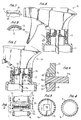
- Figure 1 is a side elevational view, partly in section, of a dispenser body having a snap-fitted closure cap for mounting the body onto the neck of a container, and incorporating the rotational resistance features of the invention;
- Figure 2 is a expanded view similar to Figure 1 illustrating the details of one of the features of the invention;
- Figures 3 and 4 are, respectively, plan views taken along the lines 3-3 and 4-4 of Figure 2;
- Figure 5 is a view similar to Figure 1 incorporating another embodiment according to the invention;
- Figure 6 is an enlarged view of the inventive feature of Figure 5;
- Figure 7 is a view taken substantially along the line 7-7 of Figure 5; and
- Figure 8 is a view taken substantially along the line 8-8 of Fugure 5.
- Turning now to the drawings where in like reference characters refer to like and corresponding parts throughout the several views, a
dispenser 10 is generally illustrated in Figure 1, the dispenser being of the trigger operated type for the dispensing of a fluid upon pumping operation. The dispenser is mounted on acontainer 11 of fluid to be dispensed upon operation of the dispenser. Although a trigger actuated dispenser is disclosed, the present invetion is adapted for use with other types of dispensers such as finger actuated dispensers and squeeze bottles, without departing from the invention. - The dispenser has an
annular portion 12 with an externalannular flange 13 adjacent itslower end wall 14. Upperannular wall 15 offlange 13 is conical as clearly shown in Figures 1 and 2. - The dispenser body is mounted on externally threaded
neck 16 of the container by the provision of aclosure cap 17 having internal threads which engage the external threads on the neck. The closure cap has a central opening bounded by an annular skirt orlip 18 to facilitate snap-fit engagement of the cap toportion 12 of the dispenser body. The skirt is conical presenting aterminal edge wall 19. And, the skirt is sufficiently flexible to permit the cap to be inserted over attachingportion 12 as the skirt flexs during the insertion process. The dispenser body and closure cap are thus snap-fitted in place withterminal edge wall 19 bearing againstupper wall 15 offlange 13. - A
gasket seal 21 is positioned betweenlower end wall 14 of the attaching portion andupper end wall 22 ofcontainer neck 16. The gasket has a central opening 23 (Fig. 3), and is mounted to the dispenser body via atube retainer 24 inserted within aninner sleeve 25 of the dispenser body, the tube retainer suspending adip tube 26 extending into the container through which fluid is suctioned during pumping upon operation oftrigger actuator 27. - As clearly shown in Figure 8, the surface of conical
upper wall 15 offlange 13 is roughened such as by the provision of tiny radially extendedribs 28 or other slip-resistant means. And, as shown in Figure 7,terminal edge wall 19 offlexible skirt 18 of the closure cap is roughened as by the provision of tiny radially extendedribs 29 or other slip-resistant means. Therefore, as the closure cap is tightened down on the container neck,ribs - In accordance with another feature of the invention, the surface of the
lower end wall 14 of attachingportion 12 is provided withratchet teeth 31, and the surface of theupper end wall 22 ofcontainer neck 16 is likewise provided withratchet teeth 32. And, opposing surfaces ofgasket seal 21 are provided withratchet teeth ratchet teeth ratchet teeth portion 12 to thereby avoid any loosening of the tightened closure cap from the container neck. - An alternative embodiment is illustrated in Figures 5 and 6 wherein
gasket seal 21A is instead fluted along its outer periphery as shown to thereby present anenlargement 35 having flaringportions gasket seal 21A is of a relatively soft material such as a foamed polyethylene such that, when assembled as shown in Figure 5,ratchet teeth portions portion 12 relative to the container. By immobilizing the gasket seal and by resisting dispenser body rotation, there is less of a tendency for the closure cap to back off from the container neck. Leakage of product from the container is therefore minimized. - From the foregoing it can be seen that a simple and economical yet highly effective approach has been taken in avoiding a loosening or "torque backoff" of the tightened closure cap after assembly. Thus, should the assembled dispenser/container be subject to vibrations or impact during storage and shipment, there is less of a tendency according to the invention for the closure cap to loosen. And, any tendency of the dispenser body to rotate about the central axis of its attaching portion relative to both the closure cap and relative to the container, is substantially resisted. Thus, any loosening of the tightened closure cap after assembly and any resulting leakage of product from the container, is avoided.
- It is to be understood that within the scope of the appended claims the invention may be practiced otherwise than as specifically described.
Claims (2)
- A dispenser (10) having an anti-loosening snap-fit closure cap mounted on a container (11) of product to be dispensed comprising a dispenser body having a cylindrical attaching portion (12), an external flange (13) on said portion (12) having an upper annular wall (15), a freely rotatable, internally threaded closure cap (17) having a flexible conical skirt (18) at one end in snap-fitting engagement with said flange (13) for positively retaining said cap (17) on said dispenser (10), the container (11) having an externally threaded neck (16) in threaded engagement with said cap (17), said attaching portion (12) having a lower edge wall (14) overlying an upper edge wall (22) of said container neck (16), said skirt (18) having a terminal edge wall (19) in tight engagement with said upper annular wall (15) upon tightening said cap (17) onto said container neck (16), characterised in that said lower edge wall (14) comprises an inner annular sealing surface portion and an outer annular portion containing ratchet teeth (31), said upper edge wall (22) comprising an inner annular sealing surface portion and an outer annular portion containing ratchet teeth (32), a gasket (21) disposed between said lower (14) and upper (22) edge walls, said gasket (21) having opposed surfaces respectively in sealing engagement with said inner surface portions, said gasket (21) further having opposed portions containing ratchet teeth (33,34) respectively in engagement with said ratchet teeth (31,32) of said outer portions of said lower (14) and upper (22) edge walls for restricting rotation of said body relative to said container (11) about a central axis of said attaching portion (12) to avoid any loosening of said tightened cap (17) from said neck (16) and to maintain the sealing engagement between said gasket (21) and said inner surface portions, said gasket (21A) alternatively having an outer annular portion of deformable material in engagement with said ratchet teeth (31,32) of said lower (14) and upper (22) edge walls, said material deforming upon said engagement for restricting rotation of said body relative to said container (11) about a central axis of said attaching portion (12) to avoid any loosening of said tightened cap (17) from said neck (16) and to maintain the sealing engagement between said gasket (21A) and said inner surface portions.
- The dispenser (10) as claimed in Claim 1, characterised in that cooperating anti-slip means is provided on said terminal edge wall (19) and on said upper annular wall (15) for resisting rotation of said body relative to said cap (17) about said central axis to further avoid any loosening of said tightened cap (17) from said neck (16) and to further maintain the sealing engagement between said gasket (21) and said inner surface portions.
Applications Claiming Priority (2)
| Application Number | Priority Date | Filing Date | Title |
|---|---|---|---|
| US500126 | 1990-03-28 | ||
| US07/500,126 US5072860A (en) | 1990-03-28 | 1990-03-28 | Anti-loosening snap-fit cap for dispenser |
Publications (3)
| Publication Number | Publication Date |
|---|---|
| EP0450234A2 EP0450234A2 (en) | 1991-10-09 |
| EP0450234A3 EP0450234A3 (en) | 1991-11-27 |
| EP0450234B1 true EP0450234B1 (en) | 1994-04-06 |
Family
ID=23988151
Family Applications (1)
| Application Number | Title | Priority Date | Filing Date |
|---|---|---|---|
| EP90314078A Expired - Lifetime EP0450234B1 (en) | 1990-03-28 | 1990-12-20 | Anti-loosening snap-fit cap for dispenser |
Country Status (12)
| Country | Link |
|---|---|
| US (1) | US5072860A (en) |
| EP (1) | EP0450234B1 (en) |
| JP (1) | JPH04222654A (en) |
| KR (1) | KR950013982B1 (en) |
| AU (1) | AU7380491A (en) |
| BR (1) | BR9101214A (en) |
| CA (1) | CA2034792A1 (en) |
| DE (1) | DE69007967T2 (en) |
| ES (1) | ES2055346T3 (en) |
| HK (1) | HK186195A (en) |
| IE (1) | IE904559A1 (en) |
| PT (1) | PT96977A (en) |
Families Citing this family (8)
| Publication number | Priority date | Publication date | Assignee | Title |
|---|---|---|---|---|
| US5238152A (en) * | 1992-02-24 | 1993-08-24 | Afa Products Inc. | Quick-locking child resistant bottle cap assembly |
| USD354226S (en) | 1992-11-06 | 1995-01-10 | Contico International, Inc. | Trigger sprayer |
| US5507418A (en) * | 1995-03-01 | 1996-04-16 | Calmar Inc. | Fluid dispenser with interference fit gasket |
| US5657910A (en) * | 1996-03-25 | 1997-08-19 | Keyser; Robert O. | Safety seal for spray dispensing container |
| EP0810036A3 (en) * | 1996-05-30 | 2000-12-27 | SHB Warenhandels- und Beteiligungs GmbH | Closure cap with integrated dispensing pump |
| US6364173B1 (en) * | 2001-02-21 | 2002-04-02 | Owens-Illinois Closure Inc. | Pump dispenser closure having snap connection |
| US6637671B2 (en) * | 2001-10-22 | 2003-10-28 | S.C. Johnson & Son, Inc. | Reduced risk dispensing of petroleum distillate based household products |
| FR3024055B1 (en) * | 2014-07-25 | 2021-07-02 | Aptar France Sas | FLUID PRODUCT DISTRIBUTION BODY. |
Family Cites Families (11)
| Publication number | Priority date | Publication date | Assignee | Title |
|---|---|---|---|---|
| US3128018A (en) * | 1961-07-07 | 1964-04-07 | Drackett Co | Fluid dispensing pump with sealing means |
| US3179306A (en) * | 1963-03-21 | 1965-04-20 | Calmar Inc | Liquid dispenser |
| US3650473A (en) * | 1970-03-13 | 1972-03-21 | Afa Corp | Liquid dispensing apparatus |
| USRE29916E (en) * | 1973-11-21 | 1979-02-20 | Bottle for sterile dispensing of flowable contents | |
| US4168788A (en) * | 1978-07-12 | 1979-09-25 | The Afa Corporation | Closure cap and dispenser body assembly |
| US4215869A (en) * | 1979-04-16 | 1980-08-05 | Garlock Inc. | Splined shaft seal article and apparatus |
| US4361256A (en) * | 1980-07-01 | 1982-11-30 | Corsette Douglas Frank | Dispenser having attached and sealed closure cap |
| US4366921A (en) * | 1981-09-28 | 1983-01-04 | Ethyl Products Company | Child-resistant closure device |
| ES273524Y (en) * | 1983-07-14 | 1985-04-16 | Monturas Y Fornituras S.A. | LIQUID PROJECTOR GUN |
| US4747498A (en) * | 1986-06-27 | 1988-05-31 | Sunbeam Plastics Corporation | Safety dispensing closure-container package |
| US4944431A (en) * | 1988-09-23 | 1990-07-31 | Blake William S | Trigger sprayer with multi-function piston |
-
1990
- 1990-03-28 US US07/500,126 patent/US5072860A/en not_active Expired - Lifetime
- 1990-12-17 IE IE455990A patent/IE904559A1/en unknown
- 1990-12-20 DE DE69007967T patent/DE69007967T2/en not_active Expired - Fee Related
- 1990-12-20 EP EP90314078A patent/EP0450234B1/en not_active Expired - Lifetime
- 1990-12-20 ES ES90314078T patent/ES2055346T3/en not_active Expired - Lifetime
-
1991
- 1991-01-23 CA CA002034792A patent/CA2034792A1/en not_active Abandoned
- 1991-01-26 KR KR1019910001336A patent/KR950013982B1/en not_active Expired - Lifetime
- 1991-02-14 JP JP3075984A patent/JPH04222654A/en active Pending
- 1991-03-08 PT PT96977A patent/PT96977A/en not_active Application Discontinuation
- 1991-03-26 AU AU73804/91A patent/AU7380491A/en not_active Abandoned
- 1991-03-27 BR BR919101214A patent/BR9101214A/en unknown
-
1995
- 1995-12-07 HK HK186195A patent/HK186195A/en not_active IP Right Cessation
Also Published As
| Publication number | Publication date |
|---|---|
| CA2034792A1 (en) | 1991-09-29 |
| EP0450234A3 (en) | 1991-11-27 |
| US5072860A (en) | 1991-12-17 |
| DE69007967D1 (en) | 1994-05-11 |
| PT96977A (en) | 1993-01-29 |
| KR950013982B1 (en) | 1995-11-20 |
| DE69007967T2 (en) | 1994-08-04 |
| BR9101214A (en) | 1991-11-05 |
| IE904559A1 (en) | 1991-10-09 |
| ES2055346T3 (en) | 1994-08-16 |
| JPH04222654A (en) | 1992-08-12 |
| EP0450234A2 (en) | 1991-10-09 |
| AU7380491A (en) | 1991-10-03 |
| KR910016386A (en) | 1991-11-05 |
| HK186195A (en) | 1995-12-15 |
Similar Documents
| Publication | Publication Date | Title |
|---|---|---|
| CA2053444C (en) | Child resistant spout package | |
| US6296156B1 (en) | Device for mounting a valve on a container, and dispenser containing a product under pressure fitted with such a device | |
| AU708953B2 (en) | Closure means for a bottle or the like | |
| EP1092643B1 (en) | Child-resistant squeeze-and-turn closure and method of manufacturing | |
| CA2014709C (en) | Tamper indicating closure having a rotary seal | |
| EP2158042B1 (en) | Bottle and valve fitment for containers | |
| US5445299A (en) | Tamper evident lock for liquid pump dispenser | |
| EP0864504A1 (en) | Closure assembly with anti-backoff feature | |
| US4361256A (en) | Dispenser having attached and sealed closure cap | |
| GB2040891A (en) | Resealable container | |
| US6142343A (en) | Cap and dust cover for an antiseptic soap dispenser | |
| WO1998058847A1 (en) | Dispensing closure with pressure actuated valve | |
| US5072860A (en) | Anti-loosening snap-fit cap for dispenser | |
| JPH11501889A (en) | Containers with lids that cannot be easily removed | |
| US5441178A (en) | Overcap for pump style dispenser | |
| US4164377A (en) | Dual-seal, ball-type dispensing package | |
| US5507418A (en) | Fluid dispenser with interference fit gasket | |
| US8439229B2 (en) | Closure system between a dispenser head and container of a device for dispensing | |
| EP0105000A2 (en) | Closure assembly | |
| US4284211A (en) | Nibbed ferrule for holding cap | |
| CN212314372U (en) | Anti-opening sliding-rotating pressing pump | |
| US5860546A (en) | Interference squeeze contour seal assembly closure having a dual thickness neck portion | |
| GB2192385A (en) | Child-resistant closure | |
| JPS621526A (en) | Method and device for connecting spray cap and bottle | |
| JP2003191994A (en) | Vertical pump type liquid ejection vessel |
Legal Events
| Date | Code | Title | Description |
|---|---|---|---|
| PUAI | Public reference made under article 153(3) epc to a published international application that has entered the european phase |
Free format text: ORIGINAL CODE: 0009012 |
|
| PUAL | Search report despatched |
Free format text: ORIGINAL CODE: 0009013 |
|
| AK | Designated contracting states |
Kind code of ref document: A2 Designated state(s): BE DE DK ES FR GB GR IT LU NL |
|
| AK | Designated contracting states |
Kind code of ref document: A3 Designated state(s): BE DE DK ES FR GB GR IT LU NL |
|
| 17P | Request for examination filed |
Effective date: 19920515 |
|
| 17Q | First examination report despatched |
Effective date: 19921008 |
|
| GRAA | (expected) grant |
Free format text: ORIGINAL CODE: 0009210 |
|
| ITF | It: translation for a ep patent filed | ||
| AK | Designated contracting states |
Kind code of ref document: B1 Designated state(s): BE DE DK ES FR GB GR IT LU NL |
|
| PG25 | Lapsed in a contracting state [announced via postgrant information from national office to epo] |
Ref country code: GR Free format text: LAPSE BECAUSE OF FAILURE TO SUBMIT A TRANSLATION OF THE DESCRIPTION OR TO PAY THE FEE WITHIN THE PRESCRIBED TIME-LIMIT Effective date: 19940406 Ref country code: DK Effective date: 19940406 |
|
| REF | Corresponds to: |
Ref document number: 69007967 Country of ref document: DE Date of ref document: 19940511 |
|
| ET | Fr: translation filed | ||
| REG | Reference to a national code |
Ref country code: ES Ref legal event code: FG2A Ref document number: 2055346 Country of ref document: ES Kind code of ref document: T3 |
|
| PLBE | No opposition filed within time limit |
Free format text: ORIGINAL CODE: 0009261 |
|
| STAA | Information on the status of an ep patent application or granted ep patent |
Free format text: STATUS: NO OPPOSITION FILED WITHIN TIME LIMIT |
|
| 26N | No opposition filed | ||
| PGFP | Annual fee paid to national office [announced via postgrant information from national office to epo] |
Ref country code: FR Payment date: 19991208 Year of fee payment: 10 |
|
| PGFP | Annual fee paid to national office [announced via postgrant information from national office to epo] |
Ref country code: GB Payment date: 19991215 Year of fee payment: 10 |
|
| PGFP | Annual fee paid to national office [announced via postgrant information from national office to epo] |
Ref country code: DE Payment date: 19991220 Year of fee payment: 10 |
|
| PGFP | Annual fee paid to national office [announced via postgrant information from national office to epo] |
Ref country code: ES Payment date: 19991221 Year of fee payment: 10 |
|
| PGFP | Annual fee paid to national office [announced via postgrant information from national office to epo] |
Ref country code: NL Payment date: 19991228 Year of fee payment: 10 |
|
| PGFP | Annual fee paid to national office [announced via postgrant information from national office to epo] |
Ref country code: LU Payment date: 20000111 Year of fee payment: 10 |
|
| PGFP | Annual fee paid to national office [announced via postgrant information from national office to epo] |
Ref country code: BE Payment date: 20000217 Year of fee payment: 10 |
|
| PG25 | Lapsed in a contracting state [announced via postgrant information from national office to epo] |
Ref country code: LU Free format text: LAPSE BECAUSE OF NON-PAYMENT OF DUE FEES Effective date: 20001220 Ref country code: GB Free format text: LAPSE BECAUSE OF NON-PAYMENT OF DUE FEES Effective date: 20001220 |
|
| PG25 | Lapsed in a contracting state [announced via postgrant information from national office to epo] |
Ref country code: BE Free format text: LAPSE BECAUSE OF NON-PAYMENT OF DUE FEES Effective date: 20001231 |
|
| BERE | Be: lapsed |
Owner name: CALMAR INC. Effective date: 20001231 |
|
| PG25 | Lapsed in a contracting state [announced via postgrant information from national office to epo] |
Ref country code: NL Free format text: LAPSE BECAUSE OF NON-PAYMENT OF DUE FEES Effective date: 20010701 |
|
| GBPC | Gb: european patent ceased through non-payment of renewal fee |
Effective date: 20001220 |
|
| PG25 | Lapsed in a contracting state [announced via postgrant information from national office to epo] |
Ref country code: FR Free format text: LAPSE BECAUSE OF NON-PAYMENT OF DUE FEES Effective date: 20010831 |
|
| NLV4 | Nl: lapsed or anulled due to non-payment of the annual fee |
Effective date: 20010701 |
|
| REG | Reference to a national code |
Ref country code: FR Ref legal event code: ST |
|
| PG25 | Lapsed in a contracting state [announced via postgrant information from national office to epo] |
Ref country code: DE Free format text: LAPSE BECAUSE OF NON-PAYMENT OF DUE FEES Effective date: 20011002 |
|
| PG25 | Lapsed in a contracting state [announced via postgrant information from national office to epo] |
Ref country code: ES Free format text: LAPSE BECAUSE OF NON-PAYMENT OF DUE FEES Effective date: 20011221 |
|
| REG | Reference to a national code |
Ref country code: ES Ref legal event code: FD2A Effective date: 20020112 |
|
| PG25 | Lapsed in a contracting state [announced via postgrant information from national office to epo] |
Ref country code: IT Free format text: LAPSE BECAUSE OF NON-PAYMENT OF DUE FEES;WARNING: LAPSES OF ITALIAN PATENTS WITH EFFECTIVE DATE BEFORE 2007 MAY HAVE OCCURRED AT ANY TIME BEFORE 2007. THE CORRECT EFFECTIVE DATE MAY BE DIFFERENT FROM THE ONE RECORDED. Effective date: 20051220 |