EP0448867B1 - Power-assist door closer - Google Patents
Power-assist door closer Download PDFInfo
- Publication number
- EP0448867B1 EP0448867B1 EP90312969A EP90312969A EP0448867B1 EP 0448867 B1 EP0448867 B1 EP 0448867B1 EP 90312969 A EP90312969 A EP 90312969A EP 90312969 A EP90312969 A EP 90312969A EP 0448867 B1 EP0448867 B1 EP 0448867B1
- Authority
- EP
- European Patent Office
- Prior art keywords
- door
- cylinder
- boss
- plunger
- passage means
- Prior art date
- Legal status (The legal status is an assumption and is not a legal conclusion. Google has not performed a legal analysis and makes no representation as to the accuracy of the status listed.)
- Expired - Lifetime
Links
Images

Classifications
-
- E—FIXED CONSTRUCTIONS
- E05—LOCKS; KEYS; WINDOW OR DOOR FITTINGS; SAFES
- E05F—DEVICES FOR MOVING WINGS INTO OPEN OR CLOSED POSITION; CHECKS FOR WINGS; WING FITTINGS NOT OTHERWISE PROVIDED FOR, CONCERNED WITH THE FUNCTIONING OF THE WING
- E05F3/00—Closers or openers with braking devices, e.g. checks; Construction of pneumatic or liquid braking devices
- E05F3/04—Closers or openers with braking devices, e.g. checks; Construction of pneumatic or liquid braking devices with liquid piston brakes
-
- E—FIXED CONSTRUCTIONS
- E05—LOCKS; KEYS; WINDOW OR DOOR FITTINGS; SAFES
- E05F—DEVICES FOR MOVING WINGS INTO OPEN OR CLOSED POSITION; CHECKS FOR WINGS; WING FITTINGS NOT OTHERWISE PROVIDED FOR, CONCERNED WITH THE FUNCTIONING OF THE WING
- E05F15/00—Power-operated mechanisms for wings
- E05F15/50—Power-operated mechanisms for wings using fluid-pressure actuators
- E05F15/53—Power-operated mechanisms for wings using fluid-pressure actuators for swinging wings
-
- E—FIXED CONSTRUCTIONS
- E05—LOCKS; KEYS; WINDOW OR DOOR FITTINGS; SAFES
- E05F—DEVICES FOR MOVING WINGS INTO OPEN OR CLOSED POSITION; CHECKS FOR WINGS; WING FITTINGS NOT OTHERWISE PROVIDED FOR, CONCERNED WITH THE FUNCTIONING OF THE WING
- E05F3/00—Closers or openers with braking devices, e.g. checks; Construction of pneumatic or liquid braking devices
- E05F3/22—Additional arrangements for closers, e.g. for holding the wing in opened or other position
- E05F3/224—Additional arrangements for closers, e.g. for holding the wing in opened or other position for assisting in opening the wing
-
- E—FIXED CONSTRUCTIONS
- E05—LOCKS; KEYS; WINDOW OR DOOR FITTINGS; SAFES
- E05Y—INDEXING SCHEME RELATING TO HINGES OR OTHER SUSPENSION DEVICES FOR DOORS, WINDOWS OR WINGS AND DEVICES FOR MOVING WINGS INTO OPEN OR CLOSED POSITION, CHECKS FOR WINGS AND WING FITTINGS NOT OTHERWISE PROVIDED FOR, CONCERNED WITH THE FUNCTIONING OF THE WING
- E05Y2201/00—Constructional elements; Accessories therefore
- E05Y2201/20—Brakes; Disengaging means, e.g. clutches; Holders, e.g. locks; Stops; Accessories therefore
- E05Y2201/21—Brakes
-
- E—FIXED CONSTRUCTIONS
- E05—LOCKS; KEYS; WINDOW OR DOOR FITTINGS; SAFES
- E05Y—INDEXING SCHEME RELATING TO HINGES OR OTHER SUSPENSION DEVICES FOR DOORS, WINDOWS OR WINGS AND DEVICES FOR MOVING WINGS INTO OPEN OR CLOSED POSITION, CHECKS FOR WINGS AND WING FITTINGS NOT OTHERWISE PROVIDED FOR, CONCERNED WITH THE FUNCTIONING OF THE WING
- E05Y2201/00—Constructional elements; Accessories therefore
- E05Y2201/20—Brakes; Disengaging means, e.g. clutches; Holders, e.g. locks; Stops; Accessories therefore
- E05Y2201/252—Brakes; Disengaging means, e.g. clutches; Holders, e.g. locks; Stops; Accessories therefore characterised by type of friction
- E05Y2201/254—Fluid or viscous friction
- E05Y2201/256—Fluid or viscous friction with pistons or vanes
-
- E—FIXED CONSTRUCTIONS
- E05—LOCKS; KEYS; WINDOW OR DOOR FITTINGS; SAFES
- E05Y—INDEXING SCHEME RELATING TO HINGES OR OTHER SUSPENSION DEVICES FOR DOORS, WINDOWS OR WINGS AND DEVICES FOR MOVING WINGS INTO OPEN OR CLOSED POSITION, CHECKS FOR WINGS AND WING FITTINGS NOT OTHERWISE PROVIDED FOR, CONCERNED WITH THE FUNCTIONING OF THE WING
- E05Y2201/00—Constructional elements; Accessories therefore
- E05Y2201/20—Brakes; Disengaging means, e.g. clutches; Holders, e.g. locks; Stops; Accessories therefore
- E05Y2201/262—Brakes; Disengaging means, e.g. clutches; Holders, e.g. locks; Stops; Accessories therefore characterised by type of motion
- E05Y2201/264—Brakes; Disengaging means, e.g. clutches; Holders, e.g. locks; Stops; Accessories therefore characterised by type of motion linear
-
- E—FIXED CONSTRUCTIONS
- E05—LOCKS; KEYS; WINDOW OR DOOR FITTINGS; SAFES
- E05Y—INDEXING SCHEME RELATING TO HINGES OR OTHER SUSPENSION DEVICES FOR DOORS, WINDOWS OR WINGS AND DEVICES FOR MOVING WINGS INTO OPEN OR CLOSED POSITION, CHECKS FOR WINGS AND WING FITTINGS NOT OTHERWISE PROVIDED FOR, CONCERNED WITH THE FUNCTIONING OF THE WING
- E05Y2201/00—Constructional elements; Accessories therefore
- E05Y2201/40—Motors; Magnets; Springs; Weights; Accessories therefore
- E05Y2201/404—Motors; Magnets; Springs; Weights; Accessories therefore characterised by the function
- E05Y2201/41—Motors; Magnets; Springs; Weights; Accessories therefore characterised by the function for closing
-
- E—FIXED CONSTRUCTIONS
- E05—LOCKS; KEYS; WINDOW OR DOOR FITTINGS; SAFES
- E05Y—INDEXING SCHEME RELATING TO HINGES OR OTHER SUSPENSION DEVICES FOR DOORS, WINDOWS OR WINGS AND DEVICES FOR MOVING WINGS INTO OPEN OR CLOSED POSITION, CHECKS FOR WINGS AND WING FITTINGS NOT OTHERWISE PROVIDED FOR, CONCERNED WITH THE FUNCTIONING OF THE WING
- E05Y2201/00—Constructional elements; Accessories therefore
- E05Y2201/40—Motors; Magnets; Springs; Weights; Accessories therefore
- E05Y2201/404—Motors; Magnets; Springs; Weights; Accessories therefore characterised by the function
- E05Y2201/422—Motors; Magnets; Springs; Weights; Accessories therefore characterised by the function for opening
-
- E—FIXED CONSTRUCTIONS
- E05—LOCKS; KEYS; WINDOW OR DOOR FITTINGS; SAFES
- E05Y—INDEXING SCHEME RELATING TO HINGES OR OTHER SUSPENSION DEVICES FOR DOORS, WINDOWS OR WINGS AND DEVICES FOR MOVING WINGS INTO OPEN OR CLOSED POSITION, CHECKS FOR WINGS AND WING FITTINGS NOT OTHERWISE PROVIDED FOR, CONCERNED WITH THE FUNCTIONING OF THE WING
- E05Y2201/00—Constructional elements; Accessories therefore
- E05Y2201/40—Motors; Magnets; Springs; Weights; Accessories therefore
- E05Y2201/43—Motors
- E05Y2201/448—Fluid motors; Details thereof
-
- E—FIXED CONSTRUCTIONS
- E05—LOCKS; KEYS; WINDOW OR DOOR FITTINGS; SAFES
- E05Y—INDEXING SCHEME RELATING TO HINGES OR OTHER SUSPENSION DEVICES FOR DOORS, WINDOWS OR WINGS AND DEVICES FOR MOVING WINGS INTO OPEN OR CLOSED POSITION, CHECKS FOR WINGS AND WING FITTINGS NOT OTHERWISE PROVIDED FOR, CONCERNED WITH THE FUNCTIONING OF THE WING
- E05Y2800/00—Details, accessories and auxiliary operations not otherwise provided for
- E05Y2800/10—Additional functions
- E05Y2800/11—Manual wing operation
- E05Y2800/112—Back driving the transmission or motor
- E05Y2800/113—Power assistance
-
- E—FIXED CONSTRUCTIONS
- E05—LOCKS; KEYS; WINDOW OR DOOR FITTINGS; SAFES
- E05Y—INDEXING SCHEME RELATING TO HINGES OR OTHER SUSPENSION DEVICES FOR DOORS, WINDOWS OR WINGS AND DEVICES FOR MOVING WINGS INTO OPEN OR CLOSED POSITION, CHECKS FOR WINGS AND WING FITTINGS NOT OTHERWISE PROVIDED FOR, CONCERNED WITH THE FUNCTIONING OF THE WING
- E05Y2900/00—Application of doors, windows, wings or fittings thereof
- E05Y2900/10—Application of doors, windows, wings or fittings thereof for buildings or parts thereof
- E05Y2900/13—Application of doors, windows, wings or fittings thereof for buildings or parts thereof characterised by the type of wing
- E05Y2900/132—Doors
Definitions
- This invention relates to a door closer which has power means to assist the opening of the door and is especially adapted for use in areas frequented by the elderly and infirm.
- the door closer of the invention is hydraulic and the means for power assist are also hydraulic.
- the invention herein is a power assist door closer having means to adjust the required movement of the door out of the frame to activate the power assist feature. Further, the present invention provides a door closer notable for its compactness and self-contained hydraulic power means.
- US 3 003 317 describes an hydraulic power-assist door closer comprising: a cylinder having a pinion mounted therein drivably connected with a drive shaft, a piston operatively disposed in the cylinder and formed with a rack engaging the pinion, a manifold block secured against the cylinder and having a boss sealingly disposed in an end of the cylinder, check valve means adapted to close as the piston moves toward the said end and open when the door is opened manually, spring means in the cylinder urging the piston in the direction of the manifold block, a pump mounted against the opposite side of the block from the cylinder and having an inlet port and a pressure outlet port disposed against the manifold block, means to drive the pump, door-opening pressure passage means in the manifold block conducting oil from the pressure outlet port through the boss and into the said end of the cylinder, door-opening return passage means in the cylinder and manifold block conducting oil from the cylinder at a point on the opposite side of the piston from the boss into the inlet port
- a door closer wherein the drive shaft is operatively connected to the door, the check valve means are located in the piston, the door-opening return passage means are conducting oil through the boss, a bleed passage means is provided in the manifold block connecting the door-opening pressure passage means and the door-opening return passage means, a door-opening speed control valve is disposed in the bleed passage means.
- the present invention includes similar elements to the closer of US 3 003 317 but also includes power assist means and door opening speed control valve means. These means are all disposed within a single manifold mounted adjacent the power end of the cylinder.
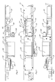
- FIG. 1 A preferred form of a door closer embodying the invention is shown in Figure 1 and generally designated 10. It comprises a base plate 12 which may be attached against a door frame immediately above the door opening.
- a closer 14 Secured to the plate 12 is a closer 14 which comprises a conventional door closer cylinder 16 having a conventional drive shaft 18. To the shaft is attached an operator arm 19 having a roller 19a which rides on a track in a door D ( Figure 1) as is conventional - see U.S. patent 4,876,764.
- a spring housing 20 To the rightward end of the closer is attached a spring housing 20 and to the leftward side is attached a manifold block 22. To the leftward side of the block 22 is the pump unit 24 driven by the electric motor 26. Appropriate electric circuitry is mounted on the board 28 and power supply wires may come into the unit through openings 30 in the base plate.
- a condenser (capacitor) 32 ( Figure 3) is connected to the motor 26 for reasons well known in the art.
- an operating arm either of the single piece, or articulated variety, has one end fixed on the lower end of the pinion shaft 18 and the other fastened to the door.
- the pump 24 which, as will be explained, pressurizes the opening side of the piston to assist in the opening, is driven by motor 26.
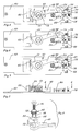
- the power to the pump motor is controlled by the switch unit which is generally designated 40 and shown in Figures 1 and 2 and 4 to 7.
- the upper end of the closer drive shaft 18 is provided with a bushing 42 ( Figure 8).
- the bushing is rigidly secured onto the shaft 18 by a bolt 44 which is screwed into a tapped opening in the upper end of the shaft.
- the bushing 24 thus turns with the pinion shaft 18.
- the section 46 of the bushing 42 is smooth and reduced. Frictionally engaging about this section is the nylon switch-operating arm 48 which receives the section 46 into its opening 50.
- the upper section 52 of the bushing 42 is knurled.
- a tear drop-shaped, rocker switch finger 54 is provided and its opening 56 receives the knurled section 52 so that the finger 54 is keyed to turn with the pinion shaft 18.
- a switch mounting plate 60 Secured to the cylinder 16 is a switch mounting plate 60. This mounts a rocker switch 62 which faces the finger 54 and is positioned so that the rocker switch will be actuated by the finger as the shaft 18 moves through its cycle. Also mounted on the plate 60 is a micro-switch 64 disposed on its side at a relatively great distance from the shaft 18 as compared with switch 62. Switch 64 has an actuator button 66. A triangular guard 67 having three legs covers the switch.
- a section of the plate 60 is struck up as at 68 and bifurcated. There adjacent is also an upward pin 70.
- a generally L-shaped stop member 72 is centrally apertured to pivotally receive the pin 70.
- One leg 74 of the stopmember 72 constitutes an abutment surface and is disposed opposite the actuator button 66.
- the other leg 76 is drilled and threaded and receives the threaded element 78 which is reduced adjacent its inner end as at 80 to be loosely embraced by the bifurcated end of the upstruck element 68.
- the shaft 18 When the door closes, the shaft 18 will rotate counterclockwise causing the shaft 48 to disengage the button 66 ( Figure 6) and swing to engage the abutment surface 74 on the stop 72. The shaft 18 continues to rotate toward the door close position, the arm 48 slipping on the bushing section 46.
- the throwing of the rocker switch 62 by the finger 54 is accomplished to control the deactivation of the motor pump unit. This is done as the shaft 18 rotates clockwise, between the Figure 4 and Figure 6 positions. In the Figure 6 position the door has just completed its opening process and the rocker switch 62 has been thrown by the finger 54. The door has now started to close as evidenced by the arm 48 being raised off the actuator button 66. Subsequently, as the shaft 18 continues counterclockwise, the finger 54 will throw the switch 62 again to ready the assembly for another door-opening phase. Such a phase will only begin, however, when the door is pushed away from its frame in an opening direction (a clockwise movement of shaft 18).
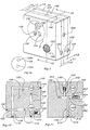
- the hydraulic circuitry for operating the cylinder is for the most part embodied in the manifold block 22.
- this block is a rectangular solid.
- On its rightward side it is formed with cylindrical boss 90 ( Figures 12 and 14) as in Simpson et al. Adjacent its outer end the boss has a peripheral recess receiving an O-ring 92.
- the boss 92 fits snugly inside the end of the cylinder 16 in sealing relation.
- journal or piston 96 there is disposed operatively within the cylinder 16 a journal or piston 96.
- the piston is provided with a central recess formed with a rack 98 which is engaged by the pinion mounted centrally on the shaft 18.
- the piston is provided with a conventional check valve 100 which permits oil within the cylinder to pass easily through the opening around the check valve 100 as the piston 96 is moved to the right in manual opening of the door. Movement of the piston to the right is opposed by the closer spring 101 enclosed in the housing 20.
- a plunger 108 is inserted into the chamber 102, the plunger stem 110 extending through the hole 104 and protruding into the chamber defined by the cylinder 16.
- a spring 112 is provided and is received into a recess in the body of the plunger 108.
- a plug 114 is screwed into the enlarged and threaded leftward end of the chamber 102 to close the chamber.
- Three separate parallelled passages 116, 118 and 120 are drilled from the back of the manifold block into the plunger chamber 102. These passages as shown are plugged adjacent the back surface of the manifold.
- the passage 116 is provided with an intersecting valve passage 122 ( Figure 10) which is enlarged to provide a seat 124 on which a threaded latch control valve 126 may be made to engage.
- the passage 122 is enlarged and threaded as shown in Figure 10 to receive valve 126.
- Passage 118 is intercepted by a perpendicular passage 128 which is plugged adjacent the bottom face of the manifold ( Figure 9).
- Passage 120 is also provided with a perpendicular passage 130 which is enlarged to provide a seat 132 and the enlargement is threaded to receive a sweep control valve 134.
- An intersecting bore 136 ( Figure 15) connects the enlargements of the passages 130, 122 and 128.
- a solenoid valve seat and chamber 140 is bored into the block 22 from the rightward base, as shown in Figures 12 and 14. Preferably, it is aligned with the plunger chamber 102.
- Figures 9, 10, 11 and 13 are oriented so that the bottom face of the manifold, normally facing down above the door when it is installed, is on the right-hand side of the Figures.
- a passage 142 ( Figure 10) is drilled through the inward end of the chamber 140 and beyond as shown, and that drilling is plugged 144 adjacent the bottom surface of the block. Intercepting the passage 142 a passage 146 is drilled from the back of the block and plugged at 148. From the top of the block (left in Figure 10), another intersecting passage 150 is drilled and plugged at 152.
- a passage 154 is drilled, the boss end of the passage 154 being covered with a filter 156 to screen debris from inside the cylinder. Passage 154 meets passage 150 ( Figure 10).
- a solenoid 158 ( Figures 1 to 3) is screwed into the threaded portion 160 of the chamber 140.
- the solenoid not shown in Figure 12, has a valve element which sits on the seat 162 of the chamber 140 when the valve is closed.
- passage 164 On the opposite side of the seat 162 ( Figure 12) from passage 142 a passage 164 is drilled and plugged as at 166. A passage 168, intersecting passage 164, is drilled from the rightward face and plugged as at 170. This also intercepts an extension of the earlier described passage 116 which joins chamber 102 towards it leftward end.
- a passage 17 is drilled and an intersecting passage 172 is drilled radially in the boss 90.
- Passage 172 aligns with a passage 174,176 in the shell of the cylinder 16 to the far end of the cylinder past piston 96 through a port (not shown).
- a passage 180 is drilled from the top of the manifold block (to the left in Figure 13), and plugged as at 182. It intercepts the plunger chamber 102 adjacent the rightward end thereof ( Figure 12). From the front wall of the manifold block an intersecting passage 184 is drilled and plugged as at 186. From the leftward face an intersecting passage 190 is drilled ( Figure 9) and enlarged on the leftward face to present an intake port 192. The intake port 192 is connected to the inlet port 192a of the pump 24 ( Figure 9a).
- the pump 24 which may be a conventional hydraulic gear-type pump, is bolted onto the manifold block in an outline P shown in dotted lines in Figure 9.
- the leftward face is formed with a keyhole-shaped opening 194 adapted to align between the gears of the pump and to provide for seal leakage.
- a pressure port 196 is formed and a passage 198 is drilled in the center of it into the block.
- the pressure port 196 is connected to the pressure port 196a of the pump 24 ( Figure 9a).
- a passage 200 is drilled intercepting passage 198, and a relief valve comprising a spring-pressed ball 202 backed by a threaded valve element 204 which is screwed into a threaded enlargement in passage 200.
- the ball 202 sits on seat 205 until excess pressure drives the ball off the seat.
- passage 206 Intercepting the seat 205 ( Figure 11), is passage 206 which is plugged as at 208. Passage 206 is intercepted by passage 120 an extension of the earlier-described passage. Passage 120 enters the rightward end of the plunger chamber 102 as shown in Figure 12. From the back wall (bottom in Figure 11) of the manifold block a passage 214 is drilled and plugged as at 212 and intercepts he passage 200. From the end of the boss 90 ( Figure 14) a pressure port 216 into the cylinder is formed and a passage 218 is drilled from there which intercepts the passage 214 ( Figure 11).
- passage 220 is drilled to intercept passage 200. Outwardly it is enlarged and threaded to receive a speed control valve 222 provided with a seat 224. Above the seat 224 the passage 220 is intercepted by an extension of passage 190, the inlet passage to the pump.
- the pressure passage has now been detailed. The sequence of operation is that when the pump is activated, oil is drawn from the far side of the cylinder through passages 176 and 174, boss passage 172 and into the right side of the plunger chamber. From there it is drawn through passage 180, ( Figure 13), 184, 190 and in through the port 192 into the pumping chamber. From the pressure side of the pump oil under pressure is pumped through passage 198, passage 200 ( Figure 11), 214 and 218 out into the chamber at the leftward side of the piston 96.
- valve 222, 224 will permit to a greater or lesser degree the circular flow of oil from the pump discharge 198 through passage 200, passage 220, valve 222, 224 and out to the pump intake 190.
- This adjustment has been designed to afford a convenient and ready control of the speed of the door opening.
- the valve 222 is on the front of the manifold in easy access ( Figure 1).
- valve 202, 204 As a pressure relief, the valve 202, 204 is provided. Should too great a pressure build up in the pump discharge line 198, 200, 214, 218 etc., the spring pressed valve 202 ( Figure 11) will give way rising from its seat and permit oil to escape through passages 206, 120 and down into the rightward end of the plunger chamber. Thus, if someone tries to force the door closed or hold the door while it is being opened, the build-up of pressure will activate the pressure relief 202, 204.
- An advantage of the structure disclosed is that in the event of power failure or the like the closer of the invention operates as a conventional non-power-assist closer.
Description
- This invention relates to a door closer which has power means to assist the opening of the door and is especially adapted for use in areas frequented by the elderly and infirm. The door closer of the invention is hydraulic and the means for power assist are also hydraulic.
- There are in the prior art a number of disclosures of power assist door openers. Usually, the power assist is the pneumatic type which, therefore, require the availability of air under pressure. Examples are: U.S. patent 4.040,144 to Lasier et al, issued August 9, 1977; U.S. patent 4,429,490 to Richard Zunkel, issued February 7, 1944; and U.S. patent 4,010,572 to Francis C. Peterson, issued March 8, 1977.
- Other power assist door openers are: 3,087,720; 3,762,099; 3,470,653; 4,222,147 and 4,339,843.
- Lacking in the power assist closers shown in the prior art are adjustable means to activate the power assist feature responsive to the distance which the door is moved out of the frame by the person opening the door. The prior art does include the aforementioned Zunkel patent which discloses a door opener which is activated as the door is moved out of its frame. However, there are no adequate means to adjust the required magnitude of the "bump".
- Further, the prior art does not disclose a compact self-contained hydraulic power assist door closer.
- The invention herein is a power assist door closer having means to adjust the required movement of the door out of the frame to activate the power assist feature. Further, the present invention provides a door closer notable for its compactness and self-contained hydraulic power means.
- The present applicant is the assignee of an earlier patent, U.S. patent 4,793,023 (Simpson et al). In this prior U.S. patent there are disclosed means for independently controlling the sweep and the latch speed of the closing door. There is further disclosed solenoid means for closing off the flow of hydraulic fluid from the pressure side of the closer so that the door may be held open in a given position. US 3 003 317 describes an hydraulic power-assist door closer comprising:
a cylinder having a pinion mounted therein drivably connected with a drive shaft,
a piston operatively disposed in the cylinder and formed with a rack engaging the pinion,
a manifold block secured against the cylinder and having a boss sealingly disposed in an end of the cylinder,
check valve means adapted to close as the piston moves toward the said end and open when the door is opened manually,
spring means in the cylinder urging the piston in the direction of the manifold block,
a pump mounted against the opposite side of the block from the cylinder and having an inlet port and a pressure outlet port disposed against the manifold block,
means to drive the pump,
door-opening pressure passage means in the manifold block conducting oil from the pressure outlet port through the boss and into the said end of the cylinder,
door-opening return passage means in the cylinder and manifold block conducting oil from the cylinder at a point on the opposite side of the piston from the boss into the inlet port of the pump. - According to the invention there is provided such a door closer wherein
the drive shaft is operatively connected to the door,
the check valve means are located in the piston,
the door-opening return passage means are conducting oil through the boss,
a bleed passage means is provided in the manifold block connecting the door-opening pressure passage means and the door-opening return passage means,
a door-opening speed control valve is disposed in the bleed passage means. - The present invention includes similar elements to the closer of US 3 003 317 but also includes power assist means and door opening speed control valve means. These means are all disposed within a single manifold mounted adjacent the power end of the cylinder.
- Other objects and features of the invention will be understood from the following specification and drawings.
- In the drawings:-
- Figure 1 is a front view of a door closer assembly embodying the invention;
- Figure 2 is a top plan view,
- Figure 3 is a bottom plan view,
- Figure 4 is a greatly enlarged top plan view partly in section of switching assembly as shown in Figure 2 and in accordance with the section line 4-4 shown in Figure 5 and showing the parts as the power assist is engaged,
- Figure 5 is a front elevational view partly in section as at line 5-5 of Figure 4,
- Figure 6 is a view showing the switch arm as it would appear as the door is closing,
- Figure 7 is a top plan view similar to Figures 4 and 6 but showing the stop means for the switch closed down to a short distance so that on subsequent opening of the door the pump is activated as the door is moved out of its frame by a lesser distance than in Figure 6,
- Figure 8 is an enlarged exploded view of the switch actuators shown in Figures 4 to 7;
- Figure 9 is a perspective view showing a manifold block embodying the invention; it is shown in position comparable to Figure 3 with the wall of the block which in assembly is against the
plate 12 is directed down in Figure 9; - Figure 9a is a simplified, reduced view of the end of the pump showing connections which mate with the openings shown in the manifold;
- Figure 10 is a sectional view taken on the line 10-10 of Figure 9;
- Figure 11 is a sectional view taken on the line 11-11 of Figure 9;
- Figure 12 is a sectional view taken on the line 12-12 of Figure 9 and showing in addition and partly in section a fragment of cylinder secured to the block;
- Figure 13 is a sectional view taken on the line 13-13 of Figure 9;
- Figure 14 is a view of the rightward face of the manifold block shown in Figure 3;
- Figure 15 is a fragmentary sectional view taken on the line 15-15 of Figure 13; and
- Figure 16 is a schematic view of the hydraulic flow circuit of a closer embodying the invention.
- A preferred form of a door closer embodying the invention is shown in Figure 1 and generally designated 10. It comprises a
base plate 12 which may be attached against a door frame immediately above the door opening. - Secured to the
plate 12 is a closer 14 which comprises a conventional doorcloser cylinder 16 having aconventional drive shaft 18. To the shaft is attached anoperator arm 19 having aroller 19a which rides on a track in a door D (Figure 1) as is conventional - see U.S. patent 4,876,764. - To the rightward end of the closer is attached a
spring housing 20 and to the leftward side is attached amanifold block 22. To the leftward side of theblock 22 is thepump unit 24 driven by theelectric motor 26. Appropriate electric circuitry is mounted on theboard 28 and power supply wires may come into the unit throughopenings 30 in the base plate. A condenser (capacitor) 32 (Figure 3) is connected to themotor 26 for reasons well known in the art. - Here, as disclosed in the above-mentioned U.S. patent 4,793,023, the
cylinder 16 contains a piston provided with a rack which meshes with a pinion disposed onshaft 18 within thecylinder 16. As is conventional, a spring which may be partly housed in thehousing 20, urges the piston leftwardly in the door-closing direction. In the more ordinary door closer arrangements the piston is driven to the right by the person opening the door. - In installation, not shown, an operating arm either of the single piece, or articulated variety, has one end fixed on the lower end of the
pinion shaft 18 and the other fastened to the door. - The
pump 24 which, as will be explained, pressurizes the opening side of the piston to assist in the opening, is driven bymotor 26. The power to the pump motor is controlled by the switch unit which is generally designated 40 and shown in Figures 1 and 2 and 4 to 7. - The upper end of the
closer drive shaft 18 is provided with a bushing 42 (Figure 8). The bushing is rigidly secured onto theshaft 18 by abolt 44 which is screwed into a tapped opening in the upper end of the shaft. Thebushing 24 thus turns with thepinion shaft 18. As shown in Figure 8, thesection 46 of thebushing 42 is smooth and reduced. Frictionally engaging about this section is the nylon switch-operating arm 48 which receives thesection 46 into itsopening 50. - The
upper section 52 of thebushing 42 is knurled. A tear drop-shaped,rocker switch finger 54 is provided and itsopening 56 receives theknurled section 52 so that thefinger 54 is keyed to turn with thepinion shaft 18. - Secured to the
cylinder 16 is aswitch mounting plate 60. This mounts arocker switch 62 which faces thefinger 54 and is positioned so that the rocker switch will be actuated by the finger as theshaft 18 moves through its cycle. Also mounted on theplate 60 is a micro-switch 64 disposed on its side at a relatively great distance from theshaft 18 as compared withswitch 62.Switch 64 has anactuator button 66. Atriangular guard 67 having three legs covers the switch. - On the opposite side of the
switch 64 from the shaft 18 a section of theplate 60 is struck up as at 68 and bifurcated. There adjacent is also anupward pin 70. A generally L-shapedstop member 72 is centrally apertured to pivotally receive thepin 70. Oneleg 74 of thestopmember 72 constitutes an abutment surface and is disposed opposite theactuator button 66. Theother leg 76 is drilled and threaded and receives the threadedelement 78 which is reduced adjacent its inner end as at 80 to be loosely embraced by the bifurcated end of theupstruck element 68. - As a result, when the threaded
element 78 is screwed in or out, thestopmember 72 pivots as shown in Figure 6 vs. Figure 7 to control the distance between theactuator button 66 and theabutment surface 74 defining the travel of thearm 48. - Putting this above-described arrangement into perspective, it will be seen that when the door starts to open and the
shaft 18 rotates clockwise (in the direction of the arrow in Figure 4), thearm 48 moves downward as shown in Figure 4 to press theactuator button 66. This activates the motor/pump unit button 66, it slips on bushing 42 (section 46) as the shaft continues to rotate. - When the door closes, the
shaft 18 will rotate counterclockwise causing theshaft 48 to disengage the button 66 (Figure 6) and swing to engage theabutment surface 74 on thestop 72. Theshaft 18 continues to rotate toward the door close position, thearm 48 slipping on thebushing section 46. - Subsequently, when the door is opened, depending on the position of the stop 72 (Figure 6 vs. Figure 7), the door will have to be moved out of its frame (i.e. bumped toward an ajar position), a greater or lesser distance for the
arm 48 to move fromabutment surface 74 to meet and depress thebutton 66. In other words, what the above-described unit accomplishes therefore, is an adjustable exact control of the amount of distance the door has to be moved out of its frame before themotor pump unit - The throwing of the
rocker switch 62 by thefinger 54 is accomplished to control the deactivation of the motor pump unit. This is done as theshaft 18 rotates clockwise, between the Figure 4 and Figure 6 positions. In the Figure 6 position the door has just completed its opening process and therocker switch 62 has been thrown by thefinger 54. The door has now started to close as evidenced by thearm 48 being raised off theactuator button 66. Subsequently, as theshaft 18 continues counterclockwise, thefinger 54 will throw theswitch 62 again to ready the assembly for another door-opening phase. Such a phase will only begin, however, when the door is pushed away from its frame in an opening direction (a clockwise movement of shaft 18). - As indicated, the hydraulic circuitry for operating the cylinder is for the most part embodied in the
manifold block 22. Outwardly, this block is a rectangular solid. On its rightward side it is formed with cylindrical boss 90 (Figures 12 and 14) as in Simpson et al. Adjacent its outer end the boss has a peripheral recess receiving an O-ring 92. As shown in Figure 2, theboss 92 fits snugly inside the end of thecylinder 16 in sealing relation. Further, there is agasket 94 disposed between the end of thecylinder 16 and the rightward face of themanifold block 22. - As shown in Figure 12, there is disposed operatively within the cylinder 16 a journal or
piston 96. As is conventional, the piston is provided with a central recess formed with arack 98 which is engaged by the pinion mounted centrally on theshaft 18. The piston is provided with aconventional check valve 100 which permits oil within the cylinder to pass easily through the opening around thecheck valve 100 as thepiston 96 is moved to the right in manual opening of the door. Movement of the piston to the right is opposed by thecloser spring 101 enclosed in thehousing 20. - From its leftward face (Figure 12), the
manifold block 22 is bored out to present a speed control orplunger chamber 102. At the rightward end of the chamber there is drilled ahole 104 which is surrounded at its rightward end by aseal 106. - As described in the above-mentioned Simpson et al patent, a
plunger 108 is inserted into thechamber 102, theplunger stem 110 extending through thehole 104 and protruding into the chamber defined by thecylinder 16. Aspring 112 is provided and is received into a recess in the body of theplunger 108. Aplug 114 is screwed into the enlarged and threaded leftward end of thechamber 102 to close the chamber. - Three separate
parallelled passages plunger chamber 102. These passages as shown are plugged adjacent the back surface of the manifold. Thepassage 116 is provided with an intersecting valve passage 122 (Figure 10) which is enlarged to provide aseat 124 on which a threadedlatch control valve 126 may be made to engage. Thepassage 122 is enlarged and threaded as shown in Figure 10 to receivevalve 126. -
Passage 118 is intercepted by aperpendicular passage 128 which is plugged adjacent the bottom face of the manifold (Figure 9).Passage 120 is also provided with aperpendicular passage 130 which is enlarged to provide aseat 132 and the enlargement is threaded to receive asweep control valve 134. An intersecting bore 136 (Figure 15) connects the enlargements of thepassages - A solenoid valve seat and
chamber 140 is bored into theblock 22 from the rightward base, as shown in Figures 12 and 14. Preferably, it is aligned with theplunger chamber 102. To show more the drawings, Figures 9, 10, 11 and 13 are oriented so that the bottom face of the manifold, normally facing down above the door when it is installed, is on the right-hand side of the Figures. - From the bottom face of the manifold bock a passage 142 (Figure 10) is drilled through the inward end of the
chamber 140 and beyond as shown, and that drilling is plugged 144 adjacent the bottom surface of the block. Intercepting the passage 142 apassage 146 is drilled from the back of the block and plugged at 148. From the top of the block (left in Figure 10), anotherintersecting passage 150 is drilled and plugged at 152. - From the outer face of the boss 90 (Figure 14), a
passage 154 is drilled, the boss end of thepassage 154 being covered with afilter 156 to screen debris from inside the cylinder.Passage 154 meets passage 150 (Figure 10). - A solenoid 158 (Figures 1 to 3) is screwed into the threaded
portion 160 of thechamber 140. The solenoid, not shown in Figure 12, has a valve element which sits on theseat 162 of thechamber 140 when the valve is closed. - On the opposite side of the seat 162 (Figure 12) from passage 142 a
passage 164 is drilled and plugged as at 166. Apassage 168, intersectingpassage 164, is drilled from the rightward face and plugged as at 170. This also intercepts an extension of the earlier describedpassage 116 which joinschamber 102 towards it leftward end. - From the rightward end of the chamber 102 (Figure 12), a passage 17 is drilled and an
intersecting passage 172 is drilled radially in theboss 90.Passage 172 aligns with a passage 174,176 in the shell of thecylinder 16 to the far end of the cylinderpast piston 96 through a port (not shown). - Thus far the hydraulic circuitry for the return flow of fluid as the door is closing has been described. In operation, with the door open and the spring 101 (Figure 12) pushing the
piston 96 leftwardly, hydraulic fluid passes through the screen 156 (Figure 14), passage 154 (Figure 10),passage solenoid chamber 140. Assuming the solenoid valve is open, the fluid then flows into passage 164 (Figure 12), 168, 116 and into theplunger chamber 102. If the solenoid valve is closed, there is no circulation of oil and the door is held open. - With the
plunger 108 in the Figure 12 position fluid exits thechamber 102 through thepassage 118,common passage 136,sweep valve passage 130 and outboss passage 172 andshell passages piston 96. - When the door closes far enough so that the
piston 96 engages thestem 110, theplunger 108 moves leftwardly to block flow of return fluid throughpassage 128. Return is then made throughpassage 116,passage 122,latch valve common passage 136,passage passage 172 andcylinder shell passages - By this means the
valve - A
passage 180 is drilled from the top of the manifold block (to the left in Figure 13), and plugged as at 182. It intercepts theplunger chamber 102 adjacent the rightward end thereof (Figure 12). From the front wall of the manifold block anintersecting passage 184 is drilled and plugged as at 186. From the leftward face anintersecting passage 190 is drilled (Figure 9) and enlarged on the leftward face to present anintake port 192. Theintake port 192 is connected to theinlet port 192a of the pump 24 (Figure 9a). - The
pump 24, which may be a conventional hydraulic gear-type pump, is bolted onto the manifold block in an outline P shown in dotted lines in Figure 9. Under theport 192 the leftward face is formed with a keyhole-shapedopening 194 adapted to align between the gears of the pump and to provide for seal leakage. - From the leftward face (Figure 9), a
pressure port 196 is formed and apassage 198 is drilled in the center of it into the block. Thepressure port 196 is connected to thepressure port 196a of the pump 24 (Figure 9a). - From the bottom wall (to the right in Figure 11), a
passage 200 is drilled interceptingpassage 198, and a relief valve comprising a spring-pressed ball 202 backed by a threadedvalve element 204 which is screwed into a threaded enlargement inpassage 200. The ball 202 sits onseat 205 until excess pressure drives the ball off the seat. - Intercepting the seat 205 (Figure 11), is
passage 206 which is plugged as at 208.Passage 206 is intercepted bypassage 120 an extension of the earlier-described passage.Passage 120 enters the rightward end of theplunger chamber 102 as shown in Figure 12. From the back wall (bottom in Figure 11) of the manifold block apassage 214 is drilled and plugged as at 212 and intercepts hepassage 200. From the end of the boss 90 (Figure 14) apressure port 216 into the cylinder is formed and apassage 218 is drilled from there which intercepts the passage 214 (Figure 11). - From the front face of the manifold block (top in Figure 11) a
passage 220 is drilled to interceptpassage 200. Outwardly it is enlarged and threaded to receive aspeed control valve 222 provided with aseat 224. Above theseat 224 thepassage 220 is intercepted by an extension ofpassage 190, the inlet passage to the pump. - The pressure passage has now been detailed. The sequence of operation is that when the pump is activated, oil is drawn from the far side of the cylinder through
passages boss passage 172 and into the right side of the plunger chamber. From there it is drawn throughpassage 180, (Figure 13), 184, 190 and in through theport 192 into the pumping chamber. From the pressure side of the pump oil under pressure is pumped throughpassage 198, passage 200 (Figure 11), 214 and 218 out into the chamber at the leftward side of thepiston 96. - It will be clear that adjustment of the
valve pump discharge 198 throughpassage 200,passage 220,valve pump intake 190. This adjustment has been designed to afford a convenient and ready control of the speed of the door opening. As can be seen, thevalve 222 is on the front of the manifold in easy access (Figure 1). - As a pressure relief, the
valve 202, 204 is provided. Should too great a pressure build up in thepump discharge line passages pressure relief 202, 204. - It is believed that the operation of the power-assisted door closer thus far described should now be clear to those skilled in the art. The various functions of the valves and passages of the
manifold block 22 have heretofore been described. - The overall operation commences when someone starts to open the door, the
shaft 18 will be turned in a clockwise direction in Figure 2 (for the hand of the door and closer herein described). This will cause thearm 48 to activate theswitch 64 which will activate thepump 24 to cause pressure fluid to enter throughport 216 into the chamber to the lefthand side ofpiston 96. This will drive thepiston 96 rightwardly to assist in the opening of the door, or, depending upon the setting ofvalve 222, will open the door with virtually no assistance of any person. When the door has reached its open position, theswitch 62 will be turned off by thefinger 54 to deactivate thepump 24. The electrical circuitry and operation has not been disclosed herein because it can be developed by one skilled in the art given the general purpose and desired operation of the closer. - In closing, the door closer oil moves inward through
filter 156 andpassage 154, through thesolenoid plunger chamber 102 throughpassage 116. With the sweep and latch valves controlling the speed of the returning piston, as described above, oil exits the plunger chamber through thepassages - An advantage of the structure disclosed is that in the event of power failure or the like the closer of the invention operates as a conventional non-power-assist closer.
- It will be clear that there has been developed and disclosed herein a power-assisted door closer of unusually compact and effective construction and which affords various adjustments of its functions to an extent not heretofore known in the art.
Claims (11)
- An hydraulic power-assist door closer (12) comprising:
a cylinder (16) having a pinion mounted therein drivably connected with a drive shaft (18),
a piston (96) operatively disposed in the cylinder (16) and formed with a rack (98) engaging the pinion,
a manifold block (22) secured against the cylinder (16) and having a boss (92) sealingly disposed in an end of the cylinder (16),
check valve means (100) adapted to close as the piston (96) moves toward the said end and open when the door (D) is opened manually,
spring means (101) in the cylinder (16) urging the piston (96) in the direction of the manifold block (22),
a pump (24) mounted against the opposite side of the block (22) from the cylinder (16) and having an inlet port (129a) and a pressure outlet port (196a) disposed against the manifold block (22),
means (26) to drive the pump (24),
door-opening pressure passage means (198,200,214,218) in the manifold block (22) conducting oil from the pressure outlet port (196a) through the boss (92) and into the said end of the cylinder (16),
door-opening return passage means (176,174,172,180, 184,190) in the cylinder (16) and manifold block (22) conducting oil from the cylinder (16) at a point on the opposite side of the piston (96) from the boss (92) into the inlet port (192a) of the pump (24),
characterised in that;
the drive shaft is operatively connected to the door (D),
the check valve means (100) are located in the piston (96),
the door-opening return passage means (176,174,172, 180,184,190) are conducting oil through the boss (92),
a bleed passage means (220) is provided in the manifold block (22) connecting the door-opening pressure passage means (198,200,214,218) and the door-opening return passage means (176,174,172,180,184,190),
a door-opening speed control valve (222) is disposed in the bleed passage means (220). - An hydraulic power assist door closer (12) according to claim 1 wich includes a plunger chamber (102) located adjacent to the boss (92) wherein on closing the door (D), oil is able to flow through the boss (92) into the plunger chamber (102) and out of said chamber (102) into the inlet port (129a) of the pump (24).
- An hydraulic power-assist door closer (12) as claimed in claim 2 wherein a pressure relief passage means (206,120) is provided in the manifold block (22) connected between the door-opening pressure passage means (198,200,214,218) and the plunger chamber (102) at the end adjacent the boss (92).
- An hydraulic power-assist door closer as claimed in claim 2 or 3 further comprising:(1) a plunger (108) in the plunger chamber (102) and having a shaft (110) extending through a sealed bore in the manifold boss (92) and into the interior of the cylinder (16) to be engaged and depressed by the piston (96) bear the end of its travel toward the manifold end, biasing means (112) urging the plunger (108) towards the cylinder (16),(2) latch passage means (122) interconnecting longitudinally spaced first and second openings (116,118) in the wall of the plunger chamber, the first opening (116) being more remote from the cylinder than the second opening (118), both openings being outward of the plunger (108) when the plunger (108) is in a first position close to the cylinder (16), and on opposite sides of the plunger (108) when the plunger (108) is moved by the piston (96) to a second position away from the cylinder (16),(3) sweep passage means (136) interconnecting the second opening (116) and a third opening (120) in the speed control chamber at a point on the opposite side of the plunger (108) from the other two openings when the plunger (108) is in the first position, and(4) door-closing passage means in the cylinder and manifold conducting oil from the cylinder (16) adjacent the boss (92) to the remote end of the plunger chamber (102) from the boss (92) and from the end of the plunger chamber (102) adjacent the boss (92) to the cylinder (16) on the opposite side of the piston (96) from the boss (92).
- An hydraulic power-assist door closer as claimed in claim 4 wherein a sweep control valve (134) is disposed in the sweep passage means and a latch control valve (126) is disposed in the latch passage means.
- An hydraulic power-assist door closer as claimed in claim 4 further including a solenoid-operated hold open valve (14) in the manifold block (22) and disposed in the door-closing passage means between the end of the cylinder (16) adjacent the manifold (22) and the remote end of the plunger chamber (102) from the boss (92).
- An hydraulic power-assist door closer as claimed in any one of the preceding claims further including:(a) a switch operator arm (48) frictionally mounted on an end of the drive shaft (18) so that the distal end of the switch operator arm (48) shuttles between two closely spaced points as the door (D) opens and closes, the switch operator arm (48) slipping on the shaft (18) after it arrives at a point and the shaft (18) continues to turn,(b) an electric switch (64) at one of the points which the arm (48) contacts and actuates to start the pump means (24) as the door (D) is moved out ot its frame.(c) stop means (72) at the other point, one of said stop means (72) and switch means (64) being adjustably positioned toward and away from the other point.
- An hydraulic power-assist door closer as claimed in claim 7 wherein the stop means (72) is adjustable.
- An hydraulic power-assist door closer as claimed in claim 7 or 8 wherein the stop means (72) comprises an L-shaped element pivoted at its apex with one leg (74) at said one point and threaded means on the other leg (76) pivots the L-shaped element.
- An hydraulic power-assist door closer as claimed in any one of claims 7 to 9, wherein a second switch (62) is provided adjacent the shaft (18) and a finger is fixedly secured to the said other end of the drive shaft (18) to engage the second switch to control the shutting down of the pump (24) after the door (D) is open.
- An hydraulic power-assist door closer as claimed in claim 4 wherein the door-closing passage means coincide with portions of the door-opening return passage means.
Applications Claiming Priority (2)
| Application Number | Priority Date | Filing Date | Title |
|---|---|---|---|
| US500023 | 1990-03-27 | ||
| US07/500,023 US4995194A (en) | 1990-03-27 | 1990-03-27 | Power-assist door closer |
Publications (2)
| Publication Number | Publication Date |
|---|---|
| EP0448867A1 EP0448867A1 (en) | 1991-10-02 |
| EP0448867B1 true EP0448867B1 (en) | 1994-04-13 |
Family
ID=23987717
Family Applications (1)
| Application Number | Title | Priority Date | Filing Date |
|---|---|---|---|
| EP90312969A Expired - Lifetime EP0448867B1 (en) | 1990-03-27 | 1990-11-29 | Power-assist door closer |
Country Status (7)
| Country | Link |
|---|---|
| US (1) | US4995194A (en) |
| EP (1) | EP0448867B1 (en) |
| JP (1) | JP2640567B2 (en) |
| AU (1) | AU643956B2 (en) |
| CA (1) | CA2029442C (en) |
| DE (1) | DE69008158T2 (en) |
| DK (1) | DK0448867T3 (en) |
Families Citing this family (45)
| Publication number | Priority date | Publication date | Assignee | Title |
|---|---|---|---|---|
| US5251400A (en) * | 1992-06-29 | 1993-10-12 | Yale Security Inc. | Control for a door closer having a power-assist opening feature |
| DE4323150B4 (en) * | 1993-07-10 | 2004-09-23 | Geze Gmbh | Swing door drive |
| CA2124403C (en) * | 1993-07-19 | 2001-12-18 | Mark A. Beran | Apparatus and method for selective alteration of operating parameters of a door |
| US5913763A (en) * | 1993-07-19 | 1999-06-22 | Dorma Door Controls, Inc. | Method for controlling the operational modes of a door in conjunction with a mechanical door control mechanism |
| AU7143596A (en) * | 1995-10-06 | 1997-04-30 | Atoma International, Inc. | Hydraulic closure system for a motor vehicle and method for operating same |
| US5651162A (en) * | 1996-01-04 | 1997-07-29 | Keszthelyi; Laszlo | Hydraulic door control system |
| US5771636A (en) * | 1996-04-10 | 1998-06-30 | Mathis; Calvin Franklin | Secure swing gate system that provides free access when power is off |
| US7438346B1 (en) | 1997-03-17 | 2008-10-21 | Automotive Technologies International, Inc. | Method and apparatus for controlling a vehicle door |
| US20040055110A1 (en) * | 1997-03-17 | 2004-03-25 | Breed David S. | Method and apparatus for controlling a vehicle door |
| US6002217A (en) * | 1997-08-19 | 1999-12-14 | Dorma Door Controls, Inc. | Door operating system |
| DE19756496C2 (en) * | 1997-12-19 | 2000-07-06 | Dorma Gmbh & Co Kg | Swing door drive |
| DE19949744B4 (en) * | 1999-10-15 | 2014-05-22 | Geze Gmbh | Drive device for a door |
| DE10029161C1 (en) | 2000-06-19 | 2002-01-24 | Dorma Gmbh & Co Kg | Arrangement for opening and closing a door or gate |
| US8225458B1 (en) | 2001-07-13 | 2012-07-24 | Hoffberg Steven M | Intelligent door restraint |
| FR2834528B1 (en) * | 2002-01-04 | 2004-02-20 | France Design | DEVICE SUITABLE FOR CONTROLLING THE OPENING AND CLOSING OF A TRUNK HOOD |
| EP1340877B1 (en) * | 2002-03-01 | 2016-05-25 | GEZE GmbH | Door drive |
| DE10300822A1 (en) * | 2003-01-10 | 2004-08-05 | Dorma Gmbh + Co. Kg | Door drive |
| DE10325027B4 (en) * | 2003-06-02 | 2007-04-05 | Dorma Gmbh + Co. Kg | Revolving door drive for an at least single-leaf door |
| US7234201B2 (en) * | 2003-07-18 | 2007-06-26 | Jackson Corporation | Door closer power adjusting device |
| US7373756B2 (en) * | 2003-09-03 | 2008-05-20 | 4378580 Canada Inc. | Automatic portable door operating system |
| US7316096B2 (en) | 2004-06-30 | 2008-01-08 | Yale Security Inc. | Door operator |
| US20060021189A1 (en) * | 2004-07-30 | 2006-02-02 | Johnson Loring M | Door closer |
| KR100737929B1 (en) * | 2005-01-04 | 2007-07-10 | 민덕기 | Door fixing device |
| MX2009011565A (en) | 2007-04-24 | 2009-11-10 | Yale Security Inc | Door closer assembly. |
| US8453382B2 (en) * | 2007-10-03 | 2013-06-04 | Stephen Kucer | Entrance control system |
| PL2356304T3 (en) * | 2008-11-14 | 2013-03-29 | Joseph Talpe | Damped actuator |
| EP2295693A1 (en) * | 2009-08-27 | 2011-03-16 | Joseph Talpe | Door closing mechanism |
| DE102009041499A1 (en) * | 2009-09-14 | 2011-03-24 | Brose Fahrzeugteile Gmbh & Co. Kommanditgesellschaft, Coburg | Locking device for locking a motor vehicle part |
| DE102009041498A1 (en) * | 2009-09-14 | 2011-03-24 | Brose Fahrzeugteile Gmbh & Co. Kommanditgesellschaft, Coburg | Locking device for locking a motor vehicle part |
| US8407937B2 (en) | 2009-10-22 | 2013-04-02 | Yale Security Inc. | Door operator |
| DE102010022051A1 (en) * | 2009-12-01 | 2011-06-09 | Dorma Gmbh + Co. Kg | Door closer with solenoid valve |
| US9163446B2 (en) * | 2010-03-17 | 2015-10-20 | Yale Security Inc. | Door control apparatus |
| US8564235B2 (en) | 2010-04-16 | 2013-10-22 | Yale Security Inc. | Self-adjusting door closer |
| US8527101B2 (en) | 2010-04-16 | 2013-09-03 | Yale Security Inc. | Door closer assembly |
| US8779713B2 (en) | 2010-04-16 | 2014-07-15 | Yale Security Inc. | Door closer with dynamically adjustable latch region parameters |
| US8415902B2 (en) | 2010-04-16 | 2013-04-09 | Yale Security Inc. | Door closer with calibration mode |
| US8547046B2 (en) | 2010-04-16 | 2013-10-01 | Yale Security Inc. | Door closer with self-powered control unit |
| US8773237B2 (en) | 2010-04-16 | 2014-07-08 | Yale Security Inc. | Door closer with teach mode |
| US8390219B2 (en) | 2010-07-29 | 2013-03-05 | Yale Security Inc. | Door operator with electrical back check feature |
| US8613126B2 (en) * | 2011-10-07 | 2013-12-24 | William Edward Blockley | Hydraulic door closure apparatus with boost |
| US20140068893A1 (en) * | 2012-09-07 | 2014-03-13 | E Tai Enterprise Co., Ltd. | Door damping apparatus and manufacturing method thereof |
| DE212013000127U1 (en) * | 2013-04-01 | 2015-02-12 | Yubo Zhong | A horizontal door closer construction |
| KR102019597B1 (en) * | 2018-03-16 | 2019-09-09 | 김경태 | Stopping device for door closer |
| DE102018206583A1 (en) * | 2018-04-27 | 2019-10-31 | Geze Gmbh | Drive unit for a swing or sliding sash and rotational position detection method in a drive unit |
| DE102018210278B4 (en) * | 2018-06-25 | 2021-03-18 | Geze Gmbh | Hydraulic, damped drive for a door or window sash |
Family Cites Families (13)
| Publication number | Priority date | Publication date | Assignee | Title |
|---|---|---|---|---|
| US393977A (en) * | 1888-12-04 | Apparatus for making gas | ||
| US2549451A (en) * | 1948-04-01 | 1951-04-17 | Hudson S Bay Company | Revolving door driving means |
| US2639142A (en) * | 1950-02-08 | 1953-05-19 | Perfection Plastic Engineering | Automatic door actuator |
| US2800323A (en) * | 1951-10-02 | 1957-07-23 | Pittsburgh Plate Glass Co | Door-operating system |
| US2910290A (en) * | 1957-01-03 | 1959-10-27 | Westinghouse Electric Corp | Door operator |
| US3003317A (en) * | 1958-07-31 | 1961-10-10 | Yale & Towne Mfg Co | Hydraulic mechanism for a door operating system |
| US3874117A (en) * | 1973-09-28 | 1975-04-01 | R H Boehm Company Inc | Electric door opener |
| US3936977A (en) * | 1973-12-27 | 1976-02-10 | Kelley Company, Inc. | Fluid activated load operator |
| US3948000A (en) * | 1974-07-25 | 1976-04-06 | Ingenjorsfirman Besam Aktiebolag | Hydraulic door openers |
| US4429490A (en) * | 1982-03-01 | 1984-02-07 | Schlage Lock Company | Door control switching device |
| JPS6094567U (en) * | 1983-12-02 | 1985-06-27 | 株式会社ナブコ | Opening door opening/closing device |
| AU6693186A (en) * | 1986-12-22 | 1988-06-23 | Tauber, T.S. | Gate operator |
| US4793023A (en) * | 1987-06-15 | 1988-12-27 | Yale Security Inc. | Door closer and holder |
-
1990
- 1990-03-27 US US07/500,023 patent/US4995194A/en not_active Expired - Lifetime
- 1990-11-07 CA CA002029442A patent/CA2029442C/en not_active Expired - Lifetime
- 1990-11-20 AU AU66749/90A patent/AU643956B2/en not_active Ceased
- 1990-11-29 DK DK90312969.0T patent/DK0448867T3/en active
- 1990-11-29 JP JP2326141A patent/JP2640567B2/en not_active Expired - Lifetime
- 1990-11-29 DE DE69008158T patent/DE69008158T2/en not_active Expired - Fee Related
- 1990-11-29 EP EP90312969A patent/EP0448867B1/en not_active Expired - Lifetime
Also Published As
| Publication number | Publication date |
|---|---|
| JPH03279575A (en) | 1991-12-10 |
| CA2029442C (en) | 1995-05-30 |
| DK0448867T3 (en) | 1994-05-16 |
| JP2640567B2 (en) | 1997-08-13 |
| DE69008158D1 (en) | 1994-05-19 |
| EP0448867A1 (en) | 1991-10-02 |
| DE69008158T2 (en) | 1994-07-28 |
| US4995194A (en) | 1991-02-26 |
| AU643956B2 (en) | 1993-12-02 |
| AU6674990A (en) | 1991-10-03 |
Similar Documents
| Publication | Publication Date | Title |
|---|---|---|
| EP0448867B1 (en) | Power-assist door closer | |
| US4793023A (en) | Door closer and holder | |
| US5251400A (en) | Control for a door closer having a power-assist opening feature | |
| US5515649A (en) | Automatic door operator | |
| CA1137127A (en) | Door closer permitting free-swing and regular-closer modes | |
| US5417011A (en) | Door opening mechanism | |
| US4856969A (en) | Fluid powered diaphragm pump with cycle timer | |
| CA2085169A1 (en) | Sensor-operated battery powered flush valve | |
| KR930021943A (en) | Electronic Control Valve | |
| CA2018716A1 (en) | Incremental electrically actuated valve | |
| GR3035424T3 (en) | Operating means for a discharge- and/or flushing valve actuated by vacuum | |
| US3195879A (en) | Automatic door operator | |
| US4175909A (en) | Valve means for use in controlling operation of a hydraulic motor | |
| EP0252554B1 (en) | Automatic door closer | |
| US4928722A (en) | Pressure relief after electric shut-off of pump | |
| EP0182408B1 (en) | Actuator and pressure adjusting unit therefore | |
| CA1308606C (en) | Hydraulic diaphragm pump method and apparatus | |
| JPS641494Y2 (en) | ||
| US2723052A (en) | Drink dispensing device | |
| CA1092942A (en) | Delaying control for hydraulic motors | |
| JPS59196941A (en) | Automatic operating apparatus for pump driven by internal-combustion engine | |
| KR0119932Y1 (en) | Noodle maker | |
| AU718315B2 (en) | Fluid actuators | |
| RU1800185C (en) | Shutoff device | |
| SU720188A2 (en) | Relief device |
Legal Events
| Date | Code | Title | Description |
|---|---|---|---|
| PUAI | Public reference made under article 153(3) epc to a published international application that has entered the european phase |
Free format text: ORIGINAL CODE: 0009012 |
|
| 17P | Request for examination filed |
Effective date: 19901217 |
|
| AK | Designated contracting states |
Kind code of ref document: A1 Designated state(s): DE DK FR GB IT SE |
|
| 17Q | First examination report despatched |
Effective date: 19920604 |
|
| GRAA | (expected) grant |
Free format text: ORIGINAL CODE: 0009210 |
|
| ITF | It: translation for a ep patent filed |
Owner name: STUDIO AVV. LIA STELLA |
|
| AK | Designated contracting states |
Kind code of ref document: B1 Designated state(s): DE DK FR GB IT SE |
|
| REG | Reference to a national code |
Ref country code: DK Ref legal event code: T3 |
|
| REF | Corresponds to: |
Ref document number: 69008158 Country of ref document: DE Date of ref document: 19940519 |
|
| ET | Fr: translation filed | ||
| EAL | Se: european patent in force in sweden |
Ref document number: 90312969.0 |
|
| PLBE | No opposition filed within time limit |
Free format text: ORIGINAL CODE: 0009261 |
|
| STAA | Information on the status of an ep patent application or granted ep patent |
Free format text: STATUS: NO OPPOSITION FILED WITHIN TIME LIMIT |
|
| 26N | No opposition filed | ||
| PGFP | Annual fee paid to national office [announced via postgrant information from national office to epo] |
Ref country code: SE Payment date: 20011106 Year of fee payment: 12 |
|
| PGFP | Annual fee paid to national office [announced via postgrant information from national office to epo] |
Ref country code: FR Payment date: 20011113 Year of fee payment: 12 Ref country code: DK Payment date: 20011113 Year of fee payment: 12 |
|
| PGFP | Annual fee paid to national office [announced via postgrant information from national office to epo] |
Ref country code: GB Payment date: 20011128 Year of fee payment: 12 |
|
| PGFP | Annual fee paid to national office [announced via postgrant information from national office to epo] |
Ref country code: DE Payment date: 20011217 Year of fee payment: 12 |
|
| REG | Reference to a national code |
Ref country code: GB Ref legal event code: IF02 |
|
| PG25 | Lapsed in a contracting state [announced via postgrant information from national office to epo] |
Ref country code: GB Free format text: LAPSE BECAUSE OF NON-PAYMENT OF DUE FEES Effective date: 20021129 |
|
| PG25 | Lapsed in a contracting state [announced via postgrant information from national office to epo] |
Ref country code: SE Free format text: LAPSE BECAUSE OF NON-PAYMENT OF DUE FEES Effective date: 20021130 |
|
| PG25 | Lapsed in a contracting state [announced via postgrant information from national office to epo] |
Ref country code: DK Free format text: LAPSE BECAUSE OF NON-PAYMENT OF DUE FEES Effective date: 20021231 |
|
| PG25 | Lapsed in a contracting state [announced via postgrant information from national office to epo] |
Ref country code: DE Free format text: LAPSE BECAUSE OF NON-PAYMENT OF DUE FEES Effective date: 20030603 |
|
| EUG | Se: european patent has lapsed | ||
| REG | Reference to a national code |
Ref country code: DK Ref legal event code: EBP |
|
| GBPC | Gb: european patent ceased through non-payment of renewal fee | ||
| PG25 | Lapsed in a contracting state [announced via postgrant information from national office to epo] |
Ref country code: FR Free format text: LAPSE BECAUSE OF NON-PAYMENT OF DUE FEES Effective date: 20030731 |
|
| REG | Reference to a national code |
Ref country code: FR Ref legal event code: ST |
|
| PG25 | Lapsed in a contracting state [announced via postgrant information from national office to epo] |
Ref country code: IT Free format text: LAPSE BECAUSE OF NON-PAYMENT OF DUE FEES Effective date: 20051129 |