EP0448303B1 - Liquid crystal display panels - Google Patents
Liquid crystal display panels Download PDFInfo
- Publication number
- EP0448303B1 EP0448303B1 EP91302234A EP91302234A EP0448303B1 EP 0448303 B1 EP0448303 B1 EP 0448303B1 EP 91302234 A EP91302234 A EP 91302234A EP 91302234 A EP91302234 A EP 91302234A EP 0448303 B1 EP0448303 B1 EP 0448303B1
- Authority
- EP
- European Patent Office
- Prior art keywords
- liquid crystal
- light
- wedge
- crystal display
- crystal cell
- Prior art date
- Legal status (The legal status is an assumption and is not a legal conclusion. Google has not performed a legal analysis and makes no representation as to the accuracy of the status listed.)
- Expired - Lifetime
Links
- 239000004973 liquid crystal related substance Substances 0.000 title claims description 94
- 210000002858 crystal cell Anatomy 0.000 claims description 37
- 239000000758 substrate Substances 0.000 claims description 27
- 238000000576 coating method Methods 0.000 claims description 18
- 239000011248 coating agent Substances 0.000 claims description 13
- 239000004033 plastic Substances 0.000 claims description 11
- 229920003023 plastic Polymers 0.000 claims description 11
- 239000000463 material Substances 0.000 claims description 6
- 230000003287 optical effect Effects 0.000 claims description 6
- 238000009877 rendering Methods 0.000 claims description 6
- 230000003190 augmentative effect Effects 0.000 claims description 3
- 230000000644 propagated effect Effects 0.000 claims description 3
- 230000008878 coupling Effects 0.000 claims description 2
- 238000010168 coupling process Methods 0.000 claims description 2
- 238000005859 coupling reaction Methods 0.000 claims description 2
- 229920001169 thermoplastic Polymers 0.000 claims description 2
- 239000004416 thermosoftening plastic Substances 0.000 claims description 2
- 210000004027 cell Anatomy 0.000 description 9
- 239000000835 fiber Substances 0.000 description 6
- 238000010276 construction Methods 0.000 description 4
- 239000013307 optical fiber Substances 0.000 description 4
- 230000005540 biological transmission Effects 0.000 description 3
- 230000009977 dual effect Effects 0.000 description 3
- XAGFODPZIPBFFR-UHFFFAOYSA-N aluminium Chemical compound [Al] XAGFODPZIPBFFR-UHFFFAOYSA-N 0.000 description 2
- 229910052782 aluminium Inorganic materials 0.000 description 2
- 230000002238 attenuated effect Effects 0.000 description 2
- 239000012799 electrically-conductive coating Substances 0.000 description 2
- 239000011521 glass Substances 0.000 description 2
- 238000005286 illumination Methods 0.000 description 2
- 230000004048 modification Effects 0.000 description 2
- 238000012986 modification Methods 0.000 description 2
- 230000000717 retained effect Effects 0.000 description 2
- 239000004793 Polystyrene Substances 0.000 description 1
- 229920006397 acrylic thermoplastic Polymers 0.000 description 1
- 230000008901 benefit Effects 0.000 description 1
- 230000001419 dependent effect Effects 0.000 description 1
- -1 for example Polymers 0.000 description 1
- AMGQUBHHOARCQH-UHFFFAOYSA-N indium;oxotin Chemical compound [In].[Sn]=O AMGQUBHHOARCQH-UHFFFAOYSA-N 0.000 description 1
- 230000001939 inductive effect Effects 0.000 description 1
- 230000031700 light absorption Effects 0.000 description 1
- 239000007788 liquid Substances 0.000 description 1
- 230000013011 mating Effects 0.000 description 1
- 230000007246 mechanism Effects 0.000 description 1
- 238000002844 melting Methods 0.000 description 1
- 230000008018 melting Effects 0.000 description 1
- 238000000034 method Methods 0.000 description 1
- 238000000465 moulding Methods 0.000 description 1
- 229920003229 poly(methyl methacrylate) Polymers 0.000 description 1
- 239000004417 polycarbonate Substances 0.000 description 1
- 229920000515 polycarbonate Polymers 0.000 description 1
- 229920002223 polystyrene Polymers 0.000 description 1
- 230000004044 response Effects 0.000 description 1
- ISXSCDLOGDJUNJ-UHFFFAOYSA-N tert-butyl prop-2-enoate Chemical compound CC(C)(C)OC(=O)C=C ISXSCDLOGDJUNJ-UHFFFAOYSA-N 0.000 description 1
Images



Classifications
-
- G—PHYSICS
- G02—OPTICS
- G02F—OPTICAL DEVICES OR ARRANGEMENTS FOR THE CONTROL OF LIGHT BY MODIFICATION OF THE OPTICAL PROPERTIES OF THE MEDIA OF THE ELEMENTS INVOLVED THEREIN; NON-LINEAR OPTICS; FREQUENCY-CHANGING OF LIGHT; OPTICAL LOGIC ELEMENTS; OPTICAL ANALOGUE/DIGITAL CONVERTERS
- G02F1/00—Devices or arrangements for the control of the intensity, colour, phase, polarisation or direction of light arriving from an independent light source, e.g. switching, gating or modulating; Non-linear optics
- G02F1/01—Devices or arrangements for the control of the intensity, colour, phase, polarisation or direction of light arriving from an independent light source, e.g. switching, gating or modulating; Non-linear optics for the control of the intensity, phase, polarisation or colour
- G02F1/13—Devices or arrangements for the control of the intensity, colour, phase, polarisation or direction of light arriving from an independent light source, e.g. switching, gating or modulating; Non-linear optics for the control of the intensity, phase, polarisation or colour based on liquid crystals, e.g. single liquid crystal display cells
- G02F1/133—Constructional arrangements; Operation of liquid crystal cells; Circuit arrangements
- G02F1/1333—Constructional arrangements; Manufacturing methods
- G02F1/1335—Structural association of cells with optical devices, e.g. polarisers or reflectors
- G02F1/1336—Illuminating devices
- G02F1/133615—Edge-illuminating devices, i.e. illuminating from the side
-
- G—PHYSICS
- G02—OPTICS
- G02F—OPTICAL DEVICES OR ARRANGEMENTS FOR THE CONTROL OF LIGHT BY MODIFICATION OF THE OPTICAL PROPERTIES OF THE MEDIA OF THE ELEMENTS INVOLVED THEREIN; NON-LINEAR OPTICS; FREQUENCY-CHANGING OF LIGHT; OPTICAL LOGIC ELEMENTS; OPTICAL ANALOGUE/DIGITAL CONVERTERS
- G02F1/00—Devices or arrangements for the control of the intensity, colour, phase, polarisation or direction of light arriving from an independent light source, e.g. switching, gating or modulating; Non-linear optics
- G02F1/01—Devices or arrangements for the control of the intensity, colour, phase, polarisation or direction of light arriving from an independent light source, e.g. switching, gating or modulating; Non-linear optics for the control of the intensity, phase, polarisation or colour
- G02F1/13—Devices or arrangements for the control of the intensity, colour, phase, polarisation or direction of light arriving from an independent light source, e.g. switching, gating or modulating; Non-linear optics for the control of the intensity, phase, polarisation or colour based on liquid crystals, e.g. single liquid crystal display cells
- G02F1/133—Constructional arrangements; Operation of liquid crystal cells; Circuit arrangements
- G02F1/1333—Constructional arrangements; Manufacturing methods
- G02F1/1347—Arrangement of liquid crystal layers or cells in which the final condition of one light beam is achieved by the addition of the effects of two or more layers or cells
- G02F1/13476—Arrangement of liquid crystal layers or cells in which the final condition of one light beam is achieved by the addition of the effects of two or more layers or cells in which at least one liquid crystal cell or layer assumes a scattering state
Definitions
- the present invention generally relates to liquid crystal display panels and, for example, to backlighting of nematic curvilinear aligned phase (NCAP) liquid crystal display panels to improve contrast of the display which is particularly suited for automotive applications.
- NCAP nematic curvilinear aligned phase
- LCDs Liquid crystal displays
- One of the principal reasons for the popularity of LCDs is their small size and low power consumption.
- the contrast of the display is limited and the angle at which the display must be viewed is critical for many LCDs which is a hindrance especially for automotive applications.
- Many LCD panels are dependent on front lighting in order to achieve significant contrast between the portion of the display that is ON and the portion that is OFF.
- the LCD material provides about 70% transmission in the ON state and 30% transmission when in the OFF state. This ratio (about 2.3) is not adequate for most purposes.
- a way the contrast is made useful is to cause the light to travel twice through the LCD by illuminating it from the front and reflecting the light back through the LCD to be viewed from the front. In this way 0.7 squared, or 0.49, is obtained when the panel is ON and 0.3 squared, or 0.09, is obtained when OFF for a ratio of 5.4, which is adequate. If slightly lower ON transmission is satisfactory, the ratio can be increased markedly.
- Using a translucent reflector in back of the LCD makes it possible to back light the panel but does not give sufficient contrast since the light only travels once through the LCD. Thus, backlighting of these single panel displays has been unsatisfactory.
- U.S. Patent No. 4,516,834 to Cascini discloses a contrast enhanced LCD comprising two substantially identical LCDs with a transflector disposed in between such that light entering from the viewing surface of the first LCD is attenuated twice by the dark areas of the first LCD, and light entering from the rear of the second LCD is also attenuated twice, once by the rear LCD and once more by the front LCD.
- An electroluminescent panel is used as a backlight source when the display is used in a transmissive mode under poor ambient light conditions.
- U.S. Patent No. 4,637,687 to Haim et al discloses a cascaded, dual cell transflective LCD which comprises a pair of LCDs spaced from one another and having a transreflective element therebetween.
- a backlight source is positioned behind the second LCD and energized when the cascaded dual LCD is operated in its transmissive mode.
- In its reflective mode ambient light passes through the front LCD and is reflected by the transreflective element to pass through the LCD to the viewer.
- the degree of contrast ratio in the reflective mode is determined by the degree of light absorption as the light passes through the unenergized background portions of the LCD twice.
- the transmissive mode light from the backlight source passes through the two LCDs, thereby providing the same contrast ratio as in the reflective mode.
- U.S. Patent No. 4,693,560 to Wiley discloses a double layer LCD which comprises first and second LCDs spaced from one another and a transflector disposed therebetween.
- the two LCDs comprise a liquid crystal material containing a dye that conforms to the structure of the liquid crystal material and a containment medium for inducing distorted alignment of the liquid crystal material which, in response to such alignment, scatters and absorbs light.
- a backlight source is placed on the nonviewing side of the second LCD.
- the Wiley display also has two modes of operation. At night, the display acts as a totally transmissive display wherein the contrast and brightness of the display are determined by the product of the performance of the two LCDs. In bright sun, the backlight source is turned OFF and the contrast ratio and brightness of the display are products of the double pass of incident light through only the front LCD.
- a backlighted liquid crystal display comprising: a first liquid crystal cell and a second liquid crystal cell disposed in an essentially aligned manner relative to one another, said first liquid crystal cell having a first chamber containing a first liquid crystal, and said second liquid crystal cell containing a second liquid crystal, said liquid crystal cells each having electrodes disposed such that a voltage can be selectively applied across portions of said first and second liquid crystals; switching means connecting said electrodes to a source of said voltage; and a source of backlight disposed in optical contact with said second liquid crystal, said backlight source being capable of providing a substantially uniform light across said second liquid crystal; characterized in that said switching means and said electrodes are arranged such that, when voltage is applied across a selected portion of said first liquid crystal rendering said selected portion transparent, voltage is prevented from being applied to a corresponding adjacent portion of said second liquid crystal thereby rendering said corresponding adjacent portion diffusely reflective; said switching means and said electrodes are further arranged such that, when said selected portion is energized, voltage is prevented from
- a display panel 10 comprising a first or front liquid crystal cell 11 comprising a pair of optically transparent substrates 12 and 13 sealed by means of a plastic or glass frit seal, not shown, to form a first chamber in which a liquid crystal guest-host solution 14 is retained.
- the cell 11 is coincident with the front surface of the panel 10.
- the liquid crystal guest-host solution 14 contains a pleochroic or dichroic dye.
- the first liquid crystal cell 11 is sandwiched with a second or back liquid crystal cell 15 comprising the substrate 13 and a third optically transparent substrate 16, also sealed by means of a plastic or glass frit seal, not shown, to form a second chamber in which a liquid crystal guest-host solution 17 is retained.
- the liquid crystal guest-host solution 17 does not contain a dye.
- the liquid crystal guest-host solutions 14 and 17 are nematic curvilinear aligned phase (NCAP) liquid crystal solutions and may be of the type disclosed in U.S. Patent No. 4,435,047 to Fergason.
- NCAP nematic curvilinear aligned phase
- the interior surfaces of the substrates 12, 13 and 16 are provided with optically transparent, electrically conductive coatings.
- substrate 12 is provided with a coating
- substrate 13 is provided with coatings 19 and 19′ applied to both surfaces since both surfaces are interior surfaces
- substrate 16 is provided with a coating 20.
- the coating 18 forms a front electrode for the liquid crystal cell 11, while the back electrode of cell 11 is the coating 19 on the surface of substrate 13 facing the interior surface of substrate 12.
- the coating 19′ on the opposite surface of substrate 13 forms the front electrode of the second liquid crystal cell 15, while the back electrode for the second cell is formed by the coating 20.
- the coatings 18, 19, 19′ and 20 may be made of indium-tin oxide deposited on the interior surfaces of the substrates in a known manner in the shape of display elements or indicia.
- the coatings 19 and 19′ are electrically connected together.
- the basic construction comprises only three electrodes and only three substrates to define the two liquid crystal cells.
- the conductive coatings 18, 19, 19′ and 20 are electrically connected so that when the front liquid crystal cell 11 is turned ON to make selected portions of it transparent, the back liquid crystal cell 15 is OFF so that corresponding portions of it are highly reflecting.
- the ON-OFF control is established by switching means which is schematically illustrated by the single pole, double throw switch 21 connected to battery 22. It will be understood that the electrical connections shown are highly schematic and that similar connections are required to turn OFF or allow no voltage to be applied to nonselected portions of the front liquid crystal cell 11 and to turn ON corresponding portions of the back liquid crystal cell 15.
- a clear plastic wedge 23 Sandwiched in the rear of the back liquid crystal cell 15, and in optical contact therewith, is a clear plastic wedge 23 which is edge lighted.
- the wedge 23 is shown as having a plurality of light rays 24a...24n to be described hereinafter with regard to Figure 3.
- the method of edge lighting the wedge 23 is also described in more detail hereinafter.
- an edge lighted clear plastic wedge 23 is placed in optical contact with the second liquid crystal cell 15. Light rays are propagated within the wedge 23 and are internally reflected except where the second liquid crystal 15 is diffusely reflecting such as that related to ray 24a to be described.
- the incident light 25a, to be described which is transmitted through the first liquid crystal cell 12 and reflected by said second liquid crystal 15 is augmented by light ray 24a from the edge lighted plastic wedge 23.
- the edge lighted wedge 23 only appears bright in the areas where the voltage across the second liquid crystal cell 15 is OFF so that the internal light rays 24a...24n of wedge 23 are being diffusely reflected. If a segment of the front liquid crystal cell 11 is ON and the corresponding segment of the back liquid cell 15 OFF, and the rest of the display reversed with regard to these ON-OFF conditions, then that segment will appear bright, as represented by light ray 24a and the rest dark with high contrast.
- the front cell is lighted as it is represented by the conditions shown a light ray 25a of ambient light which first impinges the front of display 10, then continues onto as ray 25b which is reflected internally as ray 25b which then exits the display 10 as ray 25d.
- the panel 10 in this front cell lighted condition continues to work well with even higher contrast than obtained with prior art panels.
- the function of the side lighted wedge 23 is to provide light only in those places where the field is turned OFF in the second liquid crystal cell 15. Total internal reflection is the mechanism by which a side lighted wedge 23 is able to propagate light to all parts of the LCD. Since the side lighted wedge 23 is placed in optical contact with the substrate 16, in that portion of the second liquid crystal cell 15 which is diffusely scattering, the light rays 24a...24n in the wedge 23 are able to escape into substrate 16. Use of a specular reflective coating 26 on the back of the wedge 23 further increases the brightness of which panel 10 may obtain.
- the display 10 may be enhanced with a graphic overlay 27 of any desired configuration which is applied over the front substrate 12. Further, a color filter 28 may be added to the back liquid crystal cell 15, just behind the coating 19′, to increase the contrast of the display.
- the wedge 23 may be made of a molded thermoplastic such as, for example, acrylics, polycarbonates or polystyrenes.
- a high efficiency source 36 which may be, for example, an arc lamp centrally located within a reflector preferably of a spherical shape.
- the coupling between the ends of the fibers 34 and the wedge 23 may be made by melting them together or mating in some other way so as to reduce any reflection losses and which provides for the light from the fibers to spread out in a direction perpendicular to the direction of the beam to provide uniform illumination over the front or light emitting surface 38 of wedge 23.
- the front surface 38 is arranged to be co-extensive with the second cell 16 for the embodiment of Figure 1.
- the back surface 40, shown in Figure 2 and partially shown in Figure 3, of the wedge 23 is coated with a reflecting coating.
- this reflecting coating is a specular type, such as sputtered aluminum.
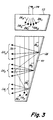
- Figure 3 illustrates the reflections of light from one of the optical fibers 34 within the volume of the wedge 23.
- the wedge 23 of Figure 3 is shown somewhat different from that of Figure 2 in that the back surface 40 is shown as converging to front surface 38.
- the challenge in back lighting an LCD is to make the illumination fairly uniform.
- the wedge 23 increases the angle of the reflections per unit distance as the wedge gets thinner and the back or reflecting surface 40 intercepts more of the light beam, shown as rays 24a...24n being emitted from fiber 34 located at the rectangular edge 33, as the light beam travels from edge 33 toward the apex of the wedge.
- the specular coating on the back surface 40 ensures that all of the light not absorbed by the surface 40 is reflected by surface 40 and comes out through the front surface 38 as groups of rays 24a, 24b and 24c.
- the substrate 16 may be formed integrally with the wedge 23 by molding plastic such that the back surface of substrate 16 forms a wedge with the front surface of substrate 16 and such that this formed wedge may be illuminated by means of fiber optics at the thick end or edge of the wedge similar to rectangular edge 33 of wedge 23.
- the source of light 36 into the fibers may be a discharge lamp within a reflector or a similar high efficiency light source such as shown in Figure 2.
- the first of these is the nature of the light beam introduced into the plastic wedge 23. Generally, it is preferred that the light beam be collimated, or nearly so, to achieve the best uniformity of illuminating light emitted from the front surface of the wedge. Secondly, the thickness and the angle of the wedge should be determined for the specific application.
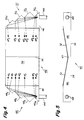
- FIGs 4 and 5 illustrate a double wedge illuminating device 42 fabricated to illuminate an LCD arrangement, in this case an automobile speedometer.
- the LCD arrangement may be such as that described with regard to Figure 1.
- the double wedge structure is used to backlight the LCD arrangement of Figure 1.
- light is collected and concentrated from a high efficiency light source (not shown) as before.
- the concentrated light is focused as an input to a pair of light guides 44 which transmit light into device 42 comprised of double wedges 46.
- the double wedge shaped device 42 is best seen in Figure 5 with regard to wedge portions 46.
- Figure 5 shows the wedge portions 46 meeting at a central portion 45
- Figure 4 shows light rays 47a...47n transmitted from fiber 44 into the device 42 at serrated edges 48 and 50.
- the edge 48 is comprised of portions 48a, 48b, 48c and 48d
- edge 50 is comprised of portions 50a, 50b, 50c and 50d.
- the expanding beams of light shown as rays 47a...47n are intercepted by serrated edges 48 and 50 which reflect the light rays 47a...47n toward the thinner central part of the double wedge device 42.
- the surfaces of the serrated edges 48 and 50 are preferably coated with a specular coating material, such as sputtered aluminum.
- the serrations are designed such that the light beams are divided into seven parts of roughly equal lumens.
- the seven distributed light beams of the serrated edges 48 and 50 are reflected by the sloped back surface 52 shown in Figure 5 of the double wedge device 42 and are emitted from the front surface 54 in the same manner as the generalized structure shown in Figure 2.
- Figure 6 shows a modification of the basic construction of Figure 1.
- the substrate 16 and the wedge 23 can be integrally molded, providing some simplification to the structure shown in Figure 1.
- Such a combined structure is indicated by reference numeral 60 in Figure 6. This may be done by using encapsulated liquid crystals, such as those described in U.S. Patents No. 4,435,047 and No. 4,616,903 to Fergason, within the plastic wedge 60.
- the electrically conductive coating 20 is applied to the back surface of the wedge 60, and only one electrically conductive coating 19 is required for the front of the wedge 60.
- the operation of the structure shown in Figure 6 is entirely equivalent to that shown in Figure 1, but with the advantage of greatly simplified construction.
Landscapes
- Physics & Mathematics (AREA)
- Nonlinear Science (AREA)
- Mathematical Physics (AREA)
- Chemical & Material Sciences (AREA)
- Crystallography & Structural Chemistry (AREA)
- General Physics & Mathematics (AREA)
- Optics & Photonics (AREA)
- Liquid Crystal (AREA)
- Planar Illumination Modules (AREA)
- Arrangements Of Lighting Devices For Vehicle Interiors, Mounting And Supporting Thereof, Circuits Therefore (AREA)
- Light Guides In General And Applications Therefor (AREA)
- Devices For Indicating Variable Information By Combining Individual Elements (AREA)
Description
- The present invention generally relates to liquid crystal display panels and, for example, to backlighting of nematic curvilinear aligned phase (NCAP) liquid crystal display panels to improve contrast of the display which is particularly suited for automotive applications.
- Liquid crystal displays (LCDs) are commonly used for a variety of applications ranging from personal televisions and computer displays to automotive applications. One of the principal reasons for the popularity of LCDs is their small size and low power consumption. On the other hand, the contrast of the display is limited and the angle at which the display must be viewed is critical for many LCDs which is a hindrance especially for automotive applications. Many LCD panels are dependent on front lighting in order to achieve significant contrast between the portion of the display that is ON and the portion that is OFF. The LCD material provides about 70% transmission in the ON state and 30% transmission when in the OFF state. This ratio (about 2.3) is not adequate for most purposes. A way the contrast is made useful is to cause the light to travel twice through the LCD by illuminating it from the front and reflecting the light back through the LCD to be viewed from the front. In this way 0.7 squared, or 0.49, is obtained when the panel is ON and 0.3 squared, or 0.09, is obtained when OFF for a ratio of 5.4, which is adequate. If slightly lower ON transmission is satisfactory, the ratio can be increased markedly. Using a translucent reflector in back of the LCD makes it possible to back light the panel but does not give sufficient contrast since the light only travels once through the LCD. Thus, backlighting of these single panel displays has been unsatisfactory.
- An approach used in the prior art to address the problem of contrast in liquid crystal displays under a variety of lighting conditions is to provide a dual panel display with two modes of operation. For example, U.S. Patent No. 4,516,834 to Cascini discloses a contrast enhanced LCD comprising two substantially identical LCDs with a transflector disposed in between such that light entering from the viewing surface of the first LCD is attenuated twice by the dark areas of the first LCD, and light entering from the rear of the second LCD is also attenuated twice, once by the rear LCD and once more by the front LCD. An electroluminescent panel is used as a backlight source when the display is used in a transmissive mode under poor ambient light conditions.
- In another example, U.S. Patent No. 4,637,687 to Haim et al discloses a cascaded, dual cell transflective LCD which comprises a pair of LCDs spaced from one another and having a transreflective element therebetween. A backlight source is positioned behind the second LCD and energized when the cascaded dual LCD is operated in its transmissive mode. In its reflective mode, ambient light passes through the front LCD and is reflected by the transreflective element to pass through the LCD to the viewer. Thus, the degree of contrast ratio in the reflective mode is determined by the degree of light absorption as the light passes through the unenergized background portions of the LCD twice. In the transmissive mode, light from the backlight source passes through the two LCDs, thereby providing the same contrast ratio as in the reflective mode.
- U.S. Patent No. 4,693,560 to Wiley discloses a double layer LCD which comprises first and second LCDs spaced from one another and a transflector disposed therebetween. The two LCDs comprise a liquid crystal material containing a dye that conforms to the structure of the liquid crystal material and a containment medium for inducing distorted alignment of the liquid crystal material which, in response to such alignment, scatters and absorbs light. A backlight source is placed on the nonviewing side of the second LCD. The Wiley display also has two modes of operation. At night, the display acts as a totally transmissive display wherein the contrast and brightness of the display are determined by the product of the performance of the two LCDs. In bright sun, the backlight source is turned OFF and the contrast ratio and brightness of the display are products of the double pass of incident light through only the front LCD.
- According to the present invention, there is provided a backlighted liquid crystal display comprising: a first liquid crystal cell and a second liquid crystal cell disposed in an essentially aligned manner relative to one another, said first liquid crystal cell having a first chamber containing a first liquid crystal, and said second liquid crystal cell containing a second liquid crystal, said liquid crystal cells each having electrodes disposed such that a voltage can be selectively applied across portions of said first and second liquid crystals; switching means connecting said electrodes to a source of said voltage; and a source of backlight disposed in optical contact with said second liquid crystal, said backlight source being capable of providing a substantially uniform light across said second liquid crystal; characterized in that said switching means and said electrodes are arranged such that, when voltage is applied across a selected portion of said first liquid crystal rendering said selected portion transparent, voltage is prevented from being applied to a corresponding adjacent portion of said second liquid crystal thereby rendering said corresponding adjacent portion diffusely reflective; said switching means and said electrodes are further arranged such that, when said selected portion is energized, voltage is prevented from being applied across non-selected portions of said first liquid crystal and coincident therewith, voltage is applied to corresponding non-selected adjacent portions of said second liquid crystal thereby rendering said non-selected adjacent portions transparent; and said backlight source is such that light propagated within said backlight source is internally reflected except where said second liquid crystal is diffusely reflective and whereby, incident light which is transmitted through said first liquid crystal cell and reflected by said second liquid crystal is augmented by light from said backlight source.
- The invention will be better understood from the following detailed description of a preferred embodiment of the invention with reference to the drawings, in which:
- Figure 1 is a cross-sectional side view of an LCD designed for back lighting using an edge-lit wedge according to the invention;
- Figure 2 is an isometric drawing of the basic wedge used to provide backlighting for the LCD;
- Figure 3 is an enlarged cross-sectional view of the wedge shaped illuminating device shown in Figure 2 illustrating the internal reflections of light within the device;
- Figure 4 is a top view of a double wedge embodiment of the invention;
- Figure 5 is an end view of the double wedge embodiment shown in Figure 4; and
- Figure 6 is a cross-sectional side view of a modification of the LCD shown in Figure 1 showing how that structure can be modified to simplify the construction of the device.
- Referring now to the drawings, and more particularly to Figure 1, there is shown a
display panel 10 comprising a first or frontliquid crystal cell 11 comprising a pair of opticallytransparent substrates host solution 14 is retained. Thecell 11 is coincident with the front surface of thepanel 10. The liquid crystal guest-host solution 14 contains a pleochroic or dichroic dye. The firstliquid crystal cell 11 is sandwiched with a second or backliquid crystal cell 15 comprising thesubstrate 13 and a third opticallytransparent substrate 16, also sealed by means of a plastic or glass frit seal, not shown, to form a second chamber in which a liquid crystal guest-host solution 17 is retained. The liquid crystal guest-host solution 17 does not contain a dye. The liquid crystal guest-host solutions 14 and 17 are nematic curvilinear aligned phase (NCAP) liquid crystal solutions and may be of the type disclosed in U.S. Patent No. 4,435,047 to Fergason. - The interior surfaces of the
substrates
electrically conductive coatings. Thus,substrate 12 is provided with acoating 18,substrate 13 is provided withcoatings substrate 16 is provided with acoating 20. Thecoating 18 forms a front electrode for theliquid crystal cell 11, while the back electrode ofcell 11 is thecoating 19 on the surface ofsubstrate 13 facing the interior surface ofsubstrate 12. Thecoating 19′ on the opposite surface ofsubstrate 13 forms the front electrode of the secondliquid crystal cell 15, while the back electrode for the second cell is formed by thecoating 20. Thecoatings coatings - The
conductive coatings liquid crystal cell 11 is turned ON to make selected portions of it transparent, the backliquid crystal cell 15 is OFF so that corresponding portions of it are highly reflecting. The ON-OFF control is established by switching means which is schematically illustrated by the single pole,double throw switch 21 connected tobattery 22. It will be understood that the electrical connections shown are highly schematic and that similar connections are required to turn OFF or allow no voltage to be applied to nonselected portions of the frontliquid crystal cell 11 and to turn ON corresponding portions of the backliquid crystal cell 15. - Sandwiched in the rear of the back
liquid crystal cell 15, and in optical contact therewith, is a clearplastic wedge 23 which is edge lighted. Thewedge 23 is shown as having a plurality oflight rays 24a...24n to be described hereinafter with regard to Figure 3. The method of edge lighting thewedge 23 is also described in more detail hereinafter. In general, an edge lighted clearplastic wedge 23 is placed in optical contact with the secondliquid crystal cell 15. Light rays are propagated within thewedge 23 and are internally reflected except where the secondliquid crystal 15 is diffusely reflecting such as that related toray 24a to be described. Theincident light 25a, to be described, which is transmitted through the firstliquid crystal cell 12 and reflected by said secondliquid crystal 15 is augmented bylight ray 24a from the edge lightedplastic wedge 23. - The edge lighted
wedge 23 only appears bright in the areas where the voltage across the secondliquid crystal cell 15 is OFF so that theinternal light rays 24a...24n ofwedge 23 are being diffusely reflected. If a segment of the frontliquid crystal cell 11 is ON and the corresponding segment of the backliquid cell 15 OFF, and the rest of the display reversed with regard to these ON-OFF conditions, then that segment will appear bright, as represented bylight ray 24a and the rest dark with high contrast. When the front cell is lighted as it is represented by the conditions shown alight ray 25a of ambient light which first impinges the front ofdisplay 10, then continues onto asray 25b which is reflected internally asray 25b which then exits thedisplay 10 asray 25d. Thepanel 10 in this front cell lighted condition continues to work well with even higher contrast than obtained with prior art panels. - The function of the side lighted
wedge 23 is to provide light only in those places where the field is turned OFF in the secondliquid crystal cell 15. Total internal reflection is the mechanism by which a side lightedwedge 23 is able to propagate light to all parts of the LCD. Since the side lightedwedge 23 is placed in optical contact with thesubstrate 16, in that portion of the secondliquid crystal cell 15 which is diffusely scattering, thelight rays 24a...24n in thewedge 23 are able to escape intosubstrate 16. Use of a specularreflective coating 26 on the back of thewedge 23 further increases the brightness of whichpanel 10 may obtain. - The
display 10 may be enhanced with agraphic overlay 27 of any desired configuration which is applied over thefront substrate 12. Further, a color filter 28 may be added to the backliquid crystal cell 15, just behind thecoating 19′, to increase the contrast of the display. - Referring now to Figure 2, there is shown a basic form of the
wedge 23. The wedge may be made of a molded thermoplastic such as, for example, acrylics, polycarbonates or polystyrenes. Along therectangular edge 33 of thewedge 23 are a plurality ofoptical fibers 34. Theoptical fibers 34 terminate in a common bundle which is positioned to collect concentrated light from ahigh efficiency source 36 which may be, for example, an arc lamp centrally located within a reflector preferably of a spherical shape. The coupling between the ends of thefibers 34 and thewedge 23 may be made by melting them together or mating in some other way so as to reduce any reflection losses and which provides for the light from the fibers to spread out in a direction perpendicular to the direction of the beam to provide uniform illumination over the front orlight emitting surface 38 ofwedge 23. Thefront surface 38 is arranged to be co-extensive with thesecond cell 16 for the embodiment of Figure 1. Theback surface 40, shown in Figure 2 and partially shown in Figure 3, of thewedge 23 is coated with a reflecting coating. Preferably, this reflecting coating is a specular type, such as sputtered aluminum. - Figure 3 illustrates the reflections of light from one of the
optical fibers 34 within the volume of thewedge 23. Thewedge 23 of Figure 3 is shown somewhat different from that of Figure 2 in that theback surface 40 is shown as converging tofront surface 38. The challenge in back lighting an LCD is to make the illumination fairly uniform. To accomplish this using edge lighting, thewedge 23 increases the angle of the reflections per unit distance as the wedge gets thinner and the back or reflectingsurface 40 intercepts more of the light beam, shown asrays 24a...24n being emitted fromfiber 34 located at therectangular edge 33, as the light beam travels fromedge 33 toward the apex of the wedge. The specular coating on theback surface 40 ensures that all of the light not absorbed by thesurface 40 is reflected bysurface 40 and comes out through thefront surface 38 as groups ofrays 24a, 24b and 24c. - Referring back to Figure 1, the
substrate 16 may be formed integrally with thewedge 23 by molding plastic such that the back surface ofsubstrate 16 forms a wedge with the front surface ofsubstrate 16 and such that this formed wedge may be illuminated by means of fiber optics at the thick end or edge of the wedge similar torectangular edge 33 ofwedge 23. For very large LCDs, it may be necessary to have a series of wedges, each fed by its own source, for example, the ends of optical fibers. As mentioned, the source of light 36 into the fibers may be a discharge lamp within a reflector or a similar high efficiency light source such as shown in Figure 2. - It will be appreciated by those skilled in the art that there are several variables that must be considered in the practice of the invention. The first of these is the nature of the light beam introduced into the
plastic wedge 23. Generally, it is preferred that the light beam be collimated, or nearly so, to achieve the best uniformity of illuminating light emitted from the front surface of the wedge. Secondly, the thickness and the angle of the wedge should be determined for the specific application. - A practical example of the invention is shown in Figures 4 and 5 which illustrate a double
wedge illuminating device 42 fabricated to illuminate an LCD arrangement, in this case an automobile speedometer. The LCD arrangement may be such as that described with regard to Figure 1. The double wedge structure is used to backlight the LCD arrangement of Figure 1. In the embodiment shown in Figures 4 and 5, light is collected and concentrated from a high efficiency light source (not shown) as before. The concentrated light is focused as an input to a pair of light guides 44 which transmit light intodevice 42 comprised ofdouble wedges 46. The double wedge shapeddevice 42 is best seen in Figure 5 with regard towedge portions 46. Figure 5 shows thewedge portions 46 meeting at acentral portion 45, whereas, Figure 4 shows light rays 47a...47n transmitted fromfiber 44 into thedevice 42 atserrated edges edge 48 is comprised ofportions edge 50 is comprised ofportions serrated edges double wedge device 42. The surfaces of theserrated edges serrated edges surface 52 shown in Figure 5 of thedouble wedge device 42 and are emitted from thefront surface 54 in the same manner as the generalized structure shown in Figure 2. - Figure 6 shows a modification of the basic construction of Figure 1. As already mentioned, the
substrate 16 and thewedge 23 can be integrally molded, providing some simplification to the structure shown in Figure 1. It is also possible to combine with thesubstrate 16 and thewedge 23, the liquid crystal 17 of the second liquid crystal andcell 15 along with thecommon substrate 13. Such a combined structure is indicated byreference numeral 60 in Figure 6. This may be done by using encapsulated liquid crystals, such as those described in U.S. Patents No. 4,435,047 and No. 4,616,903 to Fergason, within theplastic wedge 60. In this case, the electricallyconductive coating 20 is applied to the back surface of thewedge 60, and only one electricallyconductive coating 19 is required for the front of thewedge 60. The operation of the structure shown in Figure 6 is entirely equivalent to that shown in Figure 1, but with the advantage of greatly simplified construction.
Claims (9)
- A backlighted liquid crystal display (10) comprising:
a first liquid crystal cell (11) and a second liquid crystal cell (15) disposed in an essentially aligned manner relative to one another, said first liquid crystal cell (11) having a first chamber containing a first liquid crystal (14), and said second liquid crystal cell (15) containing a second liquid crystal (17), said liquid crystal cells (11, 15) each having electrodes (18, 19, 20) disposed such that a voltage can be selectively applied across portions of said first and second liquid crystals;
switching means (21) connecting said electrodes (18, 19, 20) to a source of said voltage (22); and
a source (23) of backlight disposed in optical contact with said second liquid crystal (17), said backlight source (23) being capable of providing a substantially uniform light across said second liquid crystal (17);
characterized in that
said switching means (21) and said electrodes (18, 19, 20) are arranged such that, when voltage is applied across a selected portion of said first liquid crystal (14) rendering said selected portion transparent, voltage is prevented from being applied to a corresponding adjacent portion of said second liquid crystal (17) thereby rendering said corresponding adjacent portion diffusely reflective;
said switching means (21) and said electrodes (18, 19, 20) are further arranged such that, when said selected portion is energized, voltage is prevented from being applied across non-selected portions of said first liquid crystal (14) and coincident therewith, voltage is applied to corresponding non-selected adjacent portions of said second liquid crystal (17) thereby rendering said non-selected adjacent portions transparent; and
said backlight source (23) is such that light propagated within said backlight source (23) is internally reflected except where said second liquid crystal (17) is diffusely reflective and whereby, incident light which is transmitted through said first liquid crystal cell (11) and reflected by said second liquid crystal (17) is augmented by light from said backlight source (23). - A backlighted liquid crystal display according to claim 1, wherein said first liquid crystal cell (11) has a first transparent substrate (12) coincident with a front surface of said liquid crystal display (10) and sealed with a second transparent substrate (13) to form said first chamber, and said second liquid crystal cell (15) comprises an encapsulated liquid crystal (17) contained integrally in said second substrate (13).
- A backlighted liquid crystal display according to claim 1, wherein said first liquid crystal (14) includes a dye and said second liquid crystal (17) does not include a dye.
- A backlighted liquid crystal display according to claim 1, wherein said first liquid crystal cell (11) has a first transparent substrate (12) coincident with a front surface of said liquid crystal display (10) and sealed with a second transparent substrate (13) to form said first chamber, and said second liquid crystal cell (15) comprises a second chamber containing said second liquid crystal (17), said second chamber being formed between a second pair of transparent substrates (13, 16).
- A backlighted liquid crystal display as set forth in any one of claims 1 to 4, wherein said backlight source (23) is an edge lighted wedge in optical contact with said second liquid crystal cell (15).
- A liquid crystal display as recited in claim 5, wherein said wedge (23) is formed of a plastic material.
- A backlighted liquid crystal display as recited in claim 6, further comprising a diffuse reflective coating (26) applied to a back surface (40).
- A liquid crystal display as recited in claim 5, wherein said second liquid crystal cell (15) and said wedge (23) are integrally formed (60) of a moldable thermoplastic, said plastic wedge (60) having back (40) and front (38) surfaces, at least one of which is converging, and a generally rectangular shaped edge (33) between said surfaces.
- A liquid crystal display as recited in claim 8, further comprising:
a high efficiency light source (36); and
at least one light guide (34) optically coupling light from said light source (36) to said rectangular shaped edge (33) so that light entering the plastic wedge (23) is internally reflected from the back surface (40) and emitted from said front surface (38) where said second liquid crystal cell (15) is diffusely reflecting.
Applications Claiming Priority (2)
| Application Number | Priority Date | Filing Date | Title |
|---|---|---|---|
| US07/496,395 US5283563A (en) | 1990-03-20 | 1990-03-20 | Backlighting of nematic curvilinear aligned phase liquid crystal display panels |
| US496395 | 2000-02-02 |
Publications (3)
| Publication Number | Publication Date |
|---|---|
| EP0448303A2 EP0448303A2 (en) | 1991-09-25 |
| EP0448303A3 EP0448303A3 (en) | 1992-05-06 |
| EP0448303B1 true EP0448303B1 (en) | 1995-10-18 |
Family
ID=23972441
Family Applications (1)
| Application Number | Title | Priority Date | Filing Date |
|---|---|---|---|
| EP91302234A Expired - Lifetime EP0448303B1 (en) | 1990-03-20 | 1991-03-15 | Liquid crystal display panels |
Country Status (4)
| Country | Link |
|---|---|
| US (1) | US5283563A (en) |
| EP (1) | EP0448303B1 (en) |
| JP (1) | JPH07104518B2 (en) |
| DE (1) | DE69113842T2 (en) |
Families Citing this family (24)
| Publication number | Priority date | Publication date | Assignee | Title |
|---|---|---|---|---|
| US5452113A (en) * | 1991-06-21 | 1995-09-19 | Nec Corporation | Color display element having PDLC layers and color filter |
| US6040807A (en) * | 1993-11-15 | 2000-03-21 | Sanyo Electric Co., Ltd. | Three-dimensional display |
| US5694793A (en) * | 1994-11-18 | 1997-12-09 | Kabushiki Kaisha Toshiba | Washing machine with operation panel including display device and operation switches |
| US6271898B1 (en) | 1996-09-19 | 2001-08-07 | Rohm And Haas Company | Particles and droplets containing liquid domains and method for forming in an aqueous medium |
| US5835174A (en) * | 1995-10-12 | 1998-11-10 | Rohm And Haas Company | Droplets and particles containing liquid crystal and films and apparatus containing the same |
| JP3615355B2 (en) * | 1997-06-04 | 2005-02-02 | 株式会社エンプラス | Sidelight type surface light source device and light guide plate |
| US6278425B1 (en) | 1997-06-10 | 2001-08-21 | Deluca Michael | Single array edge intersecting beam display panel |
| US6215464B1 (en) | 1997-06-10 | 2001-04-10 | Jorgen Korsgaard Jensen | Stereoscopic intersecting beam phosphorous display system |
| US6222514B1 (en) | 1997-06-10 | 2001-04-24 | Deluca Michael J. | Fault tolerant intersecting beam display panel |
| US6031511A (en) | 1997-06-10 | 2000-02-29 | Deluca; Michael J. | Multiple wave guide phosphorous display |
| JP3056133B2 (en) * | 1997-06-26 | 2000-06-26 | 静岡日本電気株式会社 | Display device |
| US6241919B1 (en) * | 1998-08-07 | 2001-06-05 | Chin-Piao Kuo | Casting polymerization for producing light guide of LCD |
| JP2000075802A (en) * | 1998-08-26 | 2000-03-14 | Matsushita Electric Ind Co Ltd | Backlight device and backlight element |
| JP2001013499A (en) * | 1999-07-01 | 2001-01-19 | Nikon Corp | Display device |
| US6663262B2 (en) * | 2001-09-10 | 2003-12-16 | 3M Innovative Properties Company | Backlighting transmissive displays |
| US20040201566A1 (en) * | 2003-04-14 | 2004-10-14 | Hsien-Hsing Wu | Display apparatus having alterable penetrative index and reflective index and method of same |
| US7349043B2 (en) * | 2004-05-24 | 2008-03-25 | Nec Corporation | Light source, display device, portable terminal device, and ray direction switching element |
| JP2006032020A (en) * | 2004-07-13 | 2006-02-02 | Sharp Corp | Liquid crystal display |
| US7545543B2 (en) * | 2004-12-09 | 2009-06-09 | Xerox Corporation | Scanner illuminator systems and methods |
| US7413328B2 (en) * | 2004-12-30 | 2008-08-19 | Honeywell International Inc. | Remotely coupled hybrid HUD backlight |
| JP5163074B2 (en) * | 2007-11-22 | 2013-03-13 | カシオ計算機株式会社 | Liquid crystal display |
| US8860910B2 (en) * | 2012-11-02 | 2014-10-14 | Shenzhen China Star Optoelectronics Technology Co., Ltd. | Backlight module and display apparatus |
| CN104251421B (en) * | 2014-07-31 | 2016-02-10 | 京东方科技集团股份有限公司 | Backlight module, display device and display packing thereof |
| CN109606251B (en) * | 2018-12-26 | 2021-10-01 | 江苏铁锚玻璃股份有限公司 | An optical structure of an automobile sunroof with both lighting and color atmosphere light effects |
Family Cites Families (14)
| Publication number | Priority date | Publication date | Assignee | Title |
|---|---|---|---|---|
| US3838565A (en) * | 1973-06-21 | 1974-10-01 | American Micro Syst | Liquid crystal display utilizing ambient light for increased contrast |
| US3897137A (en) * | 1974-01-28 | 1975-07-29 | Rockwell International Corp | Display device containing a liquid-crystal cell and a suspended-crystal cell arranged in series |
| FR2365849A1 (en) * | 1976-09-24 | 1978-04-21 | Thomson Csf | LIQUID CRYSTAL DISPLAY DEVICE |
| US4214820A (en) * | 1978-09-15 | 1980-07-29 | Timex Corporation | Electrochromic display having enhanced night viewability |
| US4487481A (en) * | 1980-03-24 | 1984-12-11 | Epson Corporation | Backlighted liquid crystal display |
| US4656466A (en) * | 1981-07-24 | 1987-04-07 | Canon Kabushiki Kaisha | Electro-optic display device |
| US4528617A (en) * | 1982-02-08 | 1985-07-09 | Sheltered Workshop For The Disabled, Inc. | Light distribution apparatus |
| US4516834A (en) * | 1983-04-08 | 1985-05-14 | Rockwell International Corporation | Contrast enhanced liquid crystal display |
| US4637687A (en) * | 1984-06-14 | 1987-01-20 | General Electric Company | Cascaded, dual cell transflective liquid crystal display |
| US4639560A (en) * | 1985-10-01 | 1987-01-27 | Chrysler Motors Corporation | Spark shield and inlet air vent for an ignition distributor |
| US4693560A (en) * | 1986-09-25 | 1987-09-15 | Taliq Corporation | Double layer display |
| GB2198867A (en) * | 1986-12-17 | 1988-06-22 | Philips Electronic Associated | A liquid crystal display illumination system |
| DE3740647C2 (en) * | 1987-12-01 | 1996-05-09 | Vdo Schindling | Liquid crystal display with two display cells arranged one behind the other |
| US4838661A (en) * | 1988-01-05 | 1989-06-13 | Motorola, Inc. | Liquid crystal light emitting display system |
-
1990
- 1990-03-20 US US07/496,395 patent/US5283563A/en not_active Expired - Fee Related
-
1991
- 1991-03-15 DE DE69113842T patent/DE69113842T2/en not_active Expired - Fee Related
- 1991-03-15 EP EP91302234A patent/EP0448303B1/en not_active Expired - Lifetime
- 1991-03-19 JP JP3078275A patent/JPH07104518B2/en not_active Expired - Lifetime
Also Published As
| Publication number | Publication date |
|---|---|
| US5283563A (en) | 1994-02-01 |
| JPH05346580A (en) | 1993-12-27 |
| DE69113842D1 (en) | 1995-11-23 |
| EP0448303A3 (en) | 1992-05-06 |
| EP0448303A2 (en) | 1991-09-25 |
| DE69113842T2 (en) | 1996-06-20 |
| JPH07104518B2 (en) | 1995-11-13 |
Similar Documents
| Publication | Publication Date | Title |
|---|---|---|
| US5283563A (en) | Backlighting of nematic curvilinear aligned phase liquid crystal display panels | |
| US5745203A (en) | Liquid crystal display device including multiple ambient light illumination modes with switchable holographic optical element | |
| US5099343A (en) | Edge-illuminated liquid crystal display devices | |
| US6151089A (en) | Reflection type display with light waveguide with inclined and planar surface sections | |
| KR100302279B1 (en) | Liquid crystal display device | |
| US20020003711A1 (en) | Displaying apparatus | |
| US20010055076A1 (en) | Reflective liquid crystal display apparatus | |
| JPH11110131A (en) | Liquid crystal display | |
| JPH11281974A (en) | Display device and electronic equipment using the same | |
| IE56117B1 (en) | Liquid crystal display device | |
| US20060033865A1 (en) | Composite display unit and electric apparatus using this | |
| JP2001166299A (en) | Light guide plate, surface light source device and liquid crystal display device | |
| US5214522A (en) | Liquid crystal display with back light and conductive diffuser | |
| US20050275933A1 (en) | In-plane switching electrophoretic display devices | |
| CA2255578C (en) | Color display device | |
| US20020030772A1 (en) | Display device | |
| JP3381133B2 (en) | Liquid crystal display | |
| JPH10186361A (en) | Display device and driving method thereof | |
| JP2651088B2 (en) | LCD panel | |
| JPH10161123A (en) | Lighting device and display device | |
| JPH06347790A (en) | Display device | |
| WO1998032047A1 (en) | Ambient illuminated electro-optic display device | |
| JPH10301109A (en) | Liquid crystal display | |
| US6166789A (en) | Liquid crystal display | |
| JP2699853B2 (en) | Display device |
Legal Events
| Date | Code | Title | Description |
|---|---|---|---|
| PUAI | Public reference made under article 153(3) epc to a published international application that has entered the european phase |
Free format text: ORIGINAL CODE: 0009012 |
|
| AK | Designated contracting states |
Kind code of ref document: A2 Designated state(s): DE FR GB NL |
|
| PUAL | Search report despatched |
Free format text: ORIGINAL CODE: 0009013 |
|
| AK | Designated contracting states |
Kind code of ref document: A3 Designated state(s): DE FR GB NL |
|
| 17P | Request for examination filed |
Effective date: 19921105 |
|
| 17Q | First examination report despatched |
Effective date: 19940516 |
|
| GRAA | (expected) grant |
Free format text: ORIGINAL CODE: 0009210 |
|
| AK | Designated contracting states |
Kind code of ref document: B1 Designated state(s): DE FR GB NL |
|
| ET | Fr: translation filed | ||
| REF | Corresponds to: |
Ref document number: 69113842 Country of ref document: DE Date of ref document: 19951123 |
|
| PLBE | No opposition filed within time limit |
Free format text: ORIGINAL CODE: 0009261 |
|
| STAA | Information on the status of an ep patent application or granted ep patent |
Free format text: STATUS: NO OPPOSITION FILED WITHIN TIME LIMIT |
|
| 26N | No opposition filed | ||
| PGFP | Annual fee paid to national office [announced via postgrant information from national office to epo] |
Ref country code: NL Payment date: 20010219 Year of fee payment: 11 Ref country code: FR Payment date: 20010219 Year of fee payment: 11 |
|
| PGFP | Annual fee paid to national office [announced via postgrant information from national office to epo] |
Ref country code: DE Payment date: 20010220 Year of fee payment: 11 |
|
| PGFP | Annual fee paid to national office [announced via postgrant information from national office to epo] |
Ref country code: GB Payment date: 20010221 Year of fee payment: 11 |
|
| REG | Reference to a national code |
Ref country code: GB Ref legal event code: IF02 |
|
| PG25 | Lapsed in a contracting state [announced via postgrant information from national office to epo] |
Ref country code: GB Free format text: LAPSE BECAUSE OF NON-PAYMENT OF DUE FEES Effective date: 20020315 |
|
| PG25 | Lapsed in a contracting state [announced via postgrant information from national office to epo] |
Ref country code: NL Free format text: LAPSE BECAUSE OF NON-PAYMENT OF DUE FEES Effective date: 20021001 Ref country code: DE Free format text: LAPSE BECAUSE OF NON-PAYMENT OF DUE FEES Effective date: 20021001 |
|
| GBPC | Gb: european patent ceased through non-payment of renewal fee |
Effective date: 20020315 |
|
| PG25 | Lapsed in a contracting state [announced via postgrant information from national office to epo] |
Ref country code: FR Free format text: LAPSE BECAUSE OF NON-PAYMENT OF DUE FEES Effective date: 20021129 |
|
| NLV4 | Nl: lapsed or anulled due to non-payment of the annual fee |
Effective date: 20021001 |
|
| REG | Reference to a national code |
Ref country code: FR Ref legal event code: ST |