EP0447987B1 - Method for synchronizing a wide area network without global synchronization - Google Patents
Method for synchronizing a wide area network without global synchronization Download PDFInfo
- Publication number
- EP0447987B1 EP0447987B1 EP19910104043 EP91104043A EP0447987B1 EP 0447987 B1 EP0447987 B1 EP 0447987B1 EP 19910104043 EP19910104043 EP 19910104043 EP 91104043 A EP91104043 A EP 91104043A EP 0447987 B1 EP0447987 B1 EP 0447987B1
- Authority
- EP
- European Patent Office
- Prior art keywords
- node
- age
- frequency
- packet
- age value
- Prior art date
- Legal status (The legal status is an assumption and is not a legal conclusion. Google has not performed a legal analysis and makes no representation as to the accuracy of the status listed.)
- Expired - Lifetime
Links
Images

Classifications
-
- H—ELECTRICITY
- H04—ELECTRIC COMMUNICATION TECHNIQUE
- H04B—TRANSMISSION
- H04B1/00—Details of transmission systems, not covered by a single one of groups H04B3/00 - H04B13/00; Details of transmission systems not characterised by the medium used for transmission
- H04B1/69—Spread spectrum techniques
- H04B1/713—Spread spectrum techniques using frequency hopping
- H04B1/7156—Arrangements for sequence synchronisation
-
- H—ELECTRICITY
- H04—ELECTRIC COMMUNICATION TECHNIQUE
- H04J—MULTIPLEX COMMUNICATION
- H04J3/00—Time-division multiplex systems
- H04J3/02—Details
- H04J3/06—Synchronising arrangements
- H04J3/0635—Clock or time synchronisation in a network
- H04J3/0638—Clock or time synchronisation among nodes; Internode synchronisation
- H04J3/0658—Clock or time synchronisation among packet nodes
- H04J3/0661—Clock or time synchronisation among packet nodes using timestamps
- H04J3/0664—Clock or time synchronisation among packet nodes using timestamps unidirectional timestamps
-
- H—ELECTRICITY
- H04—ELECTRIC COMMUNICATION TECHNIQUE
- H04J—MULTIPLEX COMMUNICATION
- H04J3/00—Time-division multiplex systems
- H04J3/02—Details
- H04J3/06—Synchronising arrangements
- H04J3/0635—Clock or time synchronisation in a network
- H04J3/0676—Mutual
Definitions
- the present invention relates to a method for operating a packet communication network and to a node for such a network according to the preamble of the independent claims
- This invention relates generally to a method for transmitting data through a communication network at radio frequencies in the presence of interference, and more particularly to a method for synchronizing information in a packet communication format on a plurality of frequencies without use of a central timing source of synchronization.
- Packet communications is a form of data communications whereby segments or packets of data are self contained as to target address, source address and information content.
- packets are routed with error checking and confirmation of receipt directly or relayed via relay stations, or intermediate nodes, between a source node or station and a destination node or station on a frequency which is known at all times to nodes within direct communication.
- Communication on certain frequencies may be restricted in duration in accordance with frequency allocation and bandwidth utilization rules and requirements. Such restrictions may be imposed by a licensing authority, such as the U.S. Federal Communications Commission (FCC).
- FCC Federal Communications Commission
- the FCC has proposed a rule that continuous transmission by a single transmitter of no more than 1 watt rf output power on any one channel be of no more than 400 ms duration each 30 seconds, and that at least some if not all other channels be selected prior to retransmission on the same frequency (FCC Rules, Part 15.247). Communication between any given pair of transceivers on a single frequency is thus restricted to packets of information which can be communicated in less than 400ms, and means must be provided to accommodate communication on other frequencies.
- frequency-agile transceivers In order to accommodate the transmission and reception of significant amounts of information in a reasonable period of time, frequency-agile transceivers have been proposed in which each transceiver changes frequency according to a pseudo-random pattern among a plurality of channels. Such systems are called frequency-hopping spread spectrum systems and are not to be confused with direct sequence spread spectrum systems wherein a pseudo-random code is used to modulate an information-bearing carrier over a broad band.
- a packet-based frequency-agile system has special difficulty in synchronizing signals, as each transceiver typically would have no knowledge of the other transceivers within communication range. What is therefore needed is a technique for acquisition and maintenance of synchronization of information transmission and reception in a frequency-agile packet communication network.
- US-A-4,850,036 discloses a frequency-hopping radio system in which a master station or control unit transmits a startup message to a plurality of slave stations on a preselected frequency.
- the startup message indicates to each slave station a frequency-hopping sequence.
- all transmissions must be synchronized to the control unit at all times to preclude interference among slaves.
- Such a system is impractical in a peer to peer network where there is no global master station or global timing.
- US-A-4,807,248 describes a method for resynchronizing frequency hopping communication systems. Resynchronization frames are transmitted interspersed with data frames following initial synchronization. This technique, which can be adapted to packet communication between two stations, requires additional signals to be sent as well as a master-slave relationship between stations.
- US-A-4,677,617 describes a frequency-hopping radio system in which a master station or control unit transmits a unique synchronization code for each time interval relative to a reference startup time. This system also proposes a master-slave relationship among stations.
- US-A-4,601,043 describes a frequency hopping system with a USART and a bit/ sync tracking circuit.
- US-A-4,558,453 describes a frequency hopping system in which keying of a transmitter automatically initiates a multiple cycle sync acquisition signal and wherein a sync maintenance signal is periodically transmitted.
- EP-A1-0 095 959 which concerns a packet communication network which operates in a frequency-hopping mode.
- the network consists of one or a plurality of master and slave stations where each slave station uses the same group of frequencies but operates according to different frequency-hopping sequences.
- the network requires the master station to broadcast a synchronization and identification to the slave station in order to get the network operable.
- O'Neill Communications LAWN® system operates a packet communication system based on AX.25 link layer protocols.
- the system uses four channels at a data rate of 38.4 kbs in the 900 MHz band in a multipoint to multipoint scheme.
- LifePoint® System operates a multipoint to point event reporting system using unacknowledged packets.
- the system occupies 800 kHz centered at 908 MHz.
- the system is used for alarm systems.
- Telesytems RadioNet SST® is a system which operates at a frequency of 915 MHz at a variety of transmission rates and power levels. The system operates without a link layer protocol.
- a frequency-hopping packet communication system without a master clock or master control unit is based on use of a receiver's frequency hopping timing and identification to control communication.
- a transmitter acquires synchronization with a target node by use of information previously received from or about a target indicating timing of present idle frequency hop of the target receiver.
- Each receiving node establishes in each station or node a table of receiver frequency hopping sequence offsets (hop timing offsets) of each other node within its communication range, and each node announces by transmission of a packet its presence on each frequency in a packet which includes a hop timing offset indicator.
- the hop timing offset indicator is a key used to read a frequency-hopping table to allow nodes to set themselves in synchronization with one another.
- a location indicator built into the address of each packet is used to randomize an ordered frequency-hopping table at each node.
- synchronized frequency hopping of two nodes is controlled by information content of the packet.
- a local clock at each node is maintained to high accuracy by a temperature compensated oscillator.
- a frequency-hopping band plan is implemented by the division of communication slots, corresponding to a fixed (or controllably variable) duration of time on one of n random frequencies, into partial slots, herein called ticks, and the accumulation of slots into epochs, wherein each epoch equals the total number of available slots (number of channels times the number of time frames per channel).
- Each pair of nodes can maintain between themselves a different frequency-hopping table based on information exchanged or heard at any time by a node receiver. It is the responsibility of the transmitting node to follow the pre-established frequency-hopping pattern for an immediate target receiver based on information the node has previously acquired.
- the frequency-hopping band plan involving the number of channels and the pseudo-random pattern of frequency change and nominal timing of changes, is universally known to each node in the network.
- FIG. 1 is a block diagram of a transceiver in accordance with the invention.
- Figure 2 is a timing diagram of a portion of an epoch according to the invention.
- Figure 3 is a representative frequency versus time graph of a frequency hopping pattern employed by all transceivers in a network according to the invention over a plurality of epochs.
- Figure 4 is a diagram of a standard data packet for use in accordance with the invention.
- Figure 5 is a timing diagram of a typical exchange between two nodes in a network according to the invention.
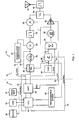
- FIG. 1 illustrates a packet node 10 in accordance with the invention.
- a large number of identical nodes having overlapping communications ranges and differing only by location and stored information comprise a communications system or network in accordance with the invention.
- Each node 10 includes a transceiver 12 and a terminal node controller (TNC) 14.
- the transceiver 12 has an antenna system 16 and means for changing frequency for receiving and transmitting as hereinafter explained.
- the TNC 14 includes packet content and frequency control functions, including means for storing information received and means for analyzing information received through the transceiver 12.
- the TNC 14 operates in accordance with at least some portions of the multiple-layer protocols established for packet communications, such as X.25 adapted for radio communications (AX.25).
- the transceiver 12 comprises a high stability local frequency reference such as a temperature controlled stable oscillator (TCXO) 18 coupled to a first, herein fixed frequency, phase locked loop (PLL) 20 under control of the TNC 14 (via control lines 22 from a CPU 24).
- the PLL 20 steers a first voltage controlled oscillator 26, which in turn provides a local reference to a mixer 28 and frequency feedback for error correction via line 30 to the first PLL 20.
- a highly-stable crystal oscillator may be employed to provide a stable reference signal to the mixer 28.
- the mixer 28 also receives an IF signal from an IF filter 30 producing an output signal containing received data to a demodulator 32.
- the demodulator 32 acts as a data filter to extract the received data, which in turn is supplied on an Rx DATA line 34 to a conventional Universal Asynchronous Receiver Transmitter (UART) 36 of the TNC 14.
- UART 36 supplies the received data in a form suited to the requirements of the CPU 24 for processing.
- the CPU 24 of the TNC 14 has coupled to it local clocks 38 for local control, read/write memory (RAM) 40 for storing volatile information, nonvolatile program memory (ROM) 42 for storing the characteristics of the TNC 14 which control operation according to the invention, and a programmable divider means 44, which serves as the source of timing used for synchronization of operation within the communication network.
- the programmable divider means 44 provides control interrupts and the like for timing epochs and ticks as hereinafter explained.
- the CPU 24 provides a control or steering signal via control lines 46 to a second, frequency-agile, phase-locked loop, and the TCXO 18 provides a timing signal via timing line 50.
- the control signal specifies the frequency of operation, the pattern of frequencies of operation and the duration of operation at each frequency of operation of the transmitted and of the received signals, or "slots" as hereinafter explained.
- the output 52 of the frequency-agile PLL 48 is summed with the transmitted data signal on Tx DATA line 54 from the UART 36 at a summer 56.
- the summer 56 is the modulator which drives a 900 MHz range voltage controlled oscillator (VCO) 60.
- VCO voltage controlled oscillator
- modulated, frequency-agile data signals are supplied to a radio frequency (rf) amplifier 62, which is enabled by a push-to-talk (PTT) control switch in response to a request to send (RTS) signal from the UART 36.
- the output of the amplifier 62 is supplied through to a transmit/receive (T/R) switch 64 which feeds the antenna 16 through an rf filter network 66.
- T/R transmit/receive
- the amplifier 62 In the absence of transmit data signals, the amplifier 62 is disabled and the 900 MHz VCO 60 provides an unmodulated signal to a second intermediate frequency (if) mixer 68 in the receive signal path.
- the receive-data if signal at the output of the mixer 68 is supplied to the bandpass filter 30 for filtering before subsequent demodulation of the data as explained hereinabove. Since the receiver section and the transmitter section share the same tuning circuitry, synchronization of the transmitted frequency and the received frequency is assured.
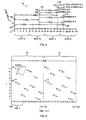
- FIG. 2 and Figure 3 there is shown a timing diagram of a portion of an "epoch" 70 in accordance with the invention, and a frequency hopping pattern for a plurality of epochs 70, 72.
- epoch a portion of an "epoch” 70 in accordance with the invention
- frequency hopping pattern for a plurality of epochs 70, 72.
- a network is a group of nodes capable of communication with one another on selected frequencies at selected times.
- a complete network is not illustrated.
- Figure 1 is representative of one of an arbitrary number of nodes in a network.
- a node 10 is a transceiving station 12 and its associated controlling means 14 within a network.
- Channels (numbered frequencies 1-11 in Fig. 3) refer to specific frequencies of operation.
- a channel has an adequate passband for the information rate of interest, and guard bands typically separate channels to minimize interchannel interference.
- Slots (A-K, Figure 3) as herein used refer to the momentary frequencies of operation in terms of specific frequencies at specific times for specific durations.
- a slot (A-K) is allocated to each available channel (1-11) in a network.
- Ticks N are markers or subdivisions of time within slots (A-K).
- a frequency hopping pattern (Frequency sequence 7,11,6,9,2,4,10,5,8,1,3 of Figure 3) is a known pseudo-random sequence of slots (A-K).
- An epoch 70 or 72 is one complete cycle of all slots A-K in a frequency-hopping pattern.
- Figure 2 illustrates four slots A,B,C,D of an epoch 70 without showing channel allocation, each slot A-D being five ticks N in duration. The significance of age of a node in terms of ticks will be apparent hereinafter.
- a packet 74 is a self-contained addressed burst of relatively short, verifiably correct data. It is typically serial binary data modulated and encoded in digital code, such as Gray code according to the USASCII character set. It contains a header portion 76 with address and certain control information, a data 78 portion and typically also a data check portion 80. As needed, it has an end of packet character (EOP) 82. The header 76 may also or alternatively contain a length designator.
- An address portion 84 includes information in definable portions about the originating station 86, the final destination station 88, the sending station 90 and the target station 92. The originating station information 86 and the target station information 88 remain unchanged for the life of the packet. The sending station information 90 and the receiving station information 92 are changed with each relay of a packet 74.
- the data check portion 80 is a calculated value, such as a Cyclic Redundancy Check (CRC) number, for each packet. It is calculated at the sending station and appended to the packet before transmission. The receiving station compares the transmitted data check portion 80 with a value calculated at the receiving station from the received data. Identity of the transmitted value and the calculated value indicates that the packet 74 has been correctly received. Error correction can be effected if the errors fall within defined parameters allowing correction by use of the check value.
- CRC Cyclic Redundancy Check
- each packet 74 has associated with it and embedded in it an age value 94, which is a tick count beginning with the anniversary of the last epoch of the sending station, as hereinafter explained.
- the age value 94 is used to interpret and propagate timing information, independent of any global clock.
- the age value is produced from a local recirculating counter embedded in the function of each TNC 14 ( Figure 1) of each node 10 and driven by a stable oscillator 18.
- Each of the oscillators 18 of each node 10 operates at nominally exactly the same frequency. The differences in age values between the received tick and the tick at the receiving station allow the receiving station to resynchronize to the sending station with every tick.
- the sending station and the receiving station switch with every exchange of packets, including any of the various types of packets employed in the system.
- the present invention employs a polling (SYNC) packet, an acknowledgement (ACK) packet, an ACK_acknowledgement (ACK_ACK) packet and an information (DATA) packet, and it may include specialized types of information packets.
- the packet information is typically sent in the form of characters or bytes of 10 bits each.
- the packet sizes in a specific embodiment are as follows:
- the header of a DATA packet may require 53 bytes, whereas the header of the ACK and ACK_ACK packets may require only 20 bytes. This is because the DATA packet must carry original source and ultimate destination information, in addition to personality information.
- Routing within a packet network is the process of using packet address information to select a path throughout the network. Addressing a packet is the placement of the header information in the packet to enable proper delivery and error recovery through the network. It is the purpose of this network to facilitate the transmission of data over a multiple-channel network in such a manner that use of any one channel of the network is limited to a duration of less than 1 second and wherein all channels are considered for utilization by a single transmitter before repeat use of a channel by the transmitter.
- the intended use is short distance point-to-point addressed transmissions or short distance point-to-multipoint addressed transmissions.
- each packet contains information on the slot timing relative to the immediate originator of the packet (whether a SYNC packet, an ACK packet or a DATA packet) to allow the local receiver to transmit a next packet at the proper synchronization in reference to slot and ticks relative to the age of the originator. It is thus the role of the node attempting to transmit a data packet to track the frequency hopping pattern and internal synchronization of the node targeted to receive the data packet.
- the maximum total occupancy time of a slot for one exchange is no more than 300ms or about 30 percent occupancy per slot for each data packet. There is adequate time for one, two or three exchanges of long packets during the same slot, as well as a greater number of shorter packets.
- a "home" slot is established.
- the home slot is the slot selected by a random offset from the first slot in terms of age of the current node (in ticks).
- the random offset "seed" may be a value derived from the node address. Any other random value can be chosen.
- the offset thus establishes a tick offset in terms of age.
- Age of each node is stored at the node as a modulo of the epoch length. Age is advanced by the local stable oscillator such that over the course of many epochs, the rate of change of age does not drift significantly as between nodes. (It should be understood that the use of a stable oscillator is merely convenient in order to minimize overly-frequent synchronization updating).
- each node After startup, each node broadcasts an announcement of its presence in the network by sending a sync packet during each slot of the network, beginning with its home slot.
- the sync packet contains its age for reception by each other node in the network. Whenever a node hears another packet from another node in the network, it notes the source and the age in its storage means for future reference. In accordance with the invention the age of the heard node is stored as an age differential relative to the receiving node. Similarly, each other node, hearing the sync packet of the startup node notes its source and age and stores that age as an age differential.
- the age is examined and stored as needed so that, when the receiving station subsequently becomes a sending station, it can use the age differential to identify the slot in which it should next transmit to that other node. Thus, it is the responsibility of the ORIGINATING station to synchronize to the receiving station.
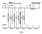
- FIG. 2 there is shown ages of three nodes normalized to the age of the node as it measures itself. Thus, all nodes have an age beginning at the origin.
- a node x having a first age from its startup of 13 ticks ( ⁇ AGE x ) time 102, as measured by the local clock at that node (Node X).
- ⁇ AGE x 13 ticks
- ⁇ AGE y 31 ticks
- Those two ages 102 and 104 are respectively loaded in the next packet transmitted by the two respective nodes as an age identifier of the transmitting node.
- a node N is characterized by an age from startup as ( ⁇ AGE N ) 106.
- the age differential between a transmitting node and a receiving node is calculated at the receiving node and stored locally in a local node table (Table I) as a DELTA tick value relative to the other node. There will be a DELTA tick value for each other node heard from by a local node.
- the value ⁇ TICK y 108 is stored in the node table of node x
- the value ⁇ TICK x 110 is stored in the node table of node y.
- ⁇ TICK x 112 stored in the node table of node N and a ⁇ TICK y 114 stored in the node table of node N.
- ⁇ TICK N 116 stored in the node table of node x
- ⁇ TICK N 118 stored in the node table of node y.
- each transmitting node the last stored ⁇ TICK value for the addressed node is used by the transmitting node to determine the exact slot and tick within the slot for the current packet transmission.
- the transmitting node which in conventional transmission is the node attempting to pass on a data packet, follows the receiving node as it hops through the spectrum of the network. Each receipt of a packet containing a ⁇ AGE value is used to update the ⁇ TICK value for the addressed node.
- the ⁇ TICK values are absolute, signed values. Therefore, it is possible for one node to report the age of another node to a third node, thereby furnishing synchronization information indirectly and minimizing the need for each node to communicate frequently with all other nodes in its broadcast range.
- Time bases, as established by local clocks can be expected to vary over time and thus the ⁇ TICK values between two nodes will tend to change over time. Since the rate and direction of change is substantially constant, it is also possible to predict timing misalignment. This further minimizes the requirement of frequent direct resynchronization.
- a requirement of frequent direct synchronization may also be used as a diagnostic index. An indication that a node requires frequent direct synchronization due to loss of synchronization indicates that the node is drifting in frequency and in need of maintenance.
- the node which is currently transmitting data synchronizes first to the receiving station or receiving node. Since both stations or nodes follow the same slot/frequency hopping pattern, they remain in sync until the interchange is completed. Thereupon both stations or nodes become idle and return to the slot/frequency hopping pattern corresponding to their respective "home" slots in an idle pattern. Any other node within its broadcast and reception range knows which slot to use to reach a particular node.
- Each node collects information about all other nodes within its range in order to facilitate communication and make a local decision about which way to direct a packet being relayed through the network.
- Table I illustrates the contents of a typical node table.
- TABLE I NODE NAME Must be unique in a network ⁇ TICK (Hop Timing offset in ticks) Calculated each time a packet is received LRA ("Last Reported Age" in slots) Optional: Used to determine whether update information is needed
- TNC 14 Key software modules employed by the TNC 14 perform the acquisition, synchronization and analysis functions of the node.
- Appendixes A, B, C, D, E and F are detailed technical descriptions of aspects of the invention. Specifically there are source code listings of several software modules which are employed to configure and operate each TNC and a description of a database employed in connection with the invention.
- Appendix A discloses one embodiment of a node definition NODE.H, a database kept by each node.
- Appendix C is a source code list describing software routines for generating and processing various types of maintenance packets, such as the synchronization packets, called synch frames. The module is designated L2MAINT.C, for level 2 maintenance processing.
- Appendix D is a source code listing describing the processing employed to calculate the ⁇ TICK value at each node. It is designated L2NODE.C for level 2 node processing. It generates the value ⁇ TICK which is used by TICKER.C above.
- Appendix E is a source code listing of a module designated L2SCAN.C used to target a next node in a message relay process in order to select the best node through which to relay a packet. It incorporates a tickle routine which performs a frequency change to a target receiver frequency, waits for the targeted receiver to come onto the frequency and then reports that the receiver is on frequency.
- Appendix F is a source code listing of a module designated L2WAN.C. This module is used indirectly to call the tickle procedure by invoking a scan for a node. It then picks the highest priority node to which the packets are to be sent. It then facilitates transmission of a string of packets to the selected receiver.
Description
- The present invention relates to a method for operating a packet communication network and to a node for such a network according to the preamble of the independent claims
- This invention relates generally to a method for transmitting data through a communication network at radio frequencies in the presence of interference, and more particularly to a method for synchronizing information in a packet communication format on a plurality of frequencies without use of a central timing source of synchronization.
- Packet communications is a form of data communications whereby segments or packets of data are self contained as to target address, source address and information content. Conventionally, packets are routed with error checking and confirmation of receipt directly or relayed via relay stations, or intermediate nodes, between a source node or station and a destination node or station on a frequency which is known at all times to nodes within direct communication. Communication on certain frequencies may be restricted in duration in accordance with frequency allocation and bandwidth utilization rules and requirements. Such restrictions may be imposed by a licensing authority, such as the U.S. Federal Communications Commission (FCC). For example, in the 902-928 MHz frequency band, the FCC has proposed a rule that continuous transmission by a single transmitter of no more than 1 watt rf output power on any one channel be of no more than 400 ms duration each 30 seconds, and that at least some if not all other channels be selected prior to retransmission on the same frequency (FCC Rules, Part 15.247). Communication between any given pair of transceivers on a single frequency is thus restricted to packets of information which can be communicated in less than 400ms, and means must be provided to accommodate communication on other frequencies.
- In order to accommodate the transmission and reception of significant amounts of information in a reasonable period of time, frequency-agile transceivers have been proposed in which each transceiver changes frequency according to a pseudo-random pattern among a plurality of channels. Such systems are called frequency-hopping spread spectrum systems and are not to be confused with direct sequence spread spectrum systems wherein a pseudo-random code is used to modulate an information-bearing carrier over a broad band.
- A packet-based frequency-agile system has special difficulty in synchronizing signals, as each transceiver typically would have no knowledge of the other transceivers within communication range. What is therefore needed is a technique for acquisition and maintenance of synchronization of information transmission and reception in a frequency-agile packet communication network.
- The following patents were uncovered in a search of the records of the U.S. Patent and Trademark Office:
- US-A-4,850,036, discloses a frequency-hopping radio system in which a master station or control unit transmits a startup message to a plurality of slave stations on a preselected frequency. The startup message indicates to each slave station a frequency-hopping sequence. Therein, all transmissions must be synchronized to the control unit at all times to preclude interference among slaves. Such a system is impractical in a peer to peer network where there is no global master station or global timing.
- US-A-4,837,823, describes a frequency-hopping communication system wherein synchronization information is transmitted over a spread of frequencies of a type which differs from the type used for data communication, and a counter at each receiver is used to keep track of sequence and synchronization. Such a scheme as therein described requires substantial acquisition time and overhead.
- US-A-4,807,248 describes a method for resynchronizing frequency hopping communication systems. Resynchronization frames are transmitted interspersed with data frames following initial synchronization. This technique, which can be adapted to packet communication between two stations, requires additional signals to be sent as well as a master-slave relationship between stations.
- US-A-4,677,617 describes a frequency-hopping radio system in which a master station or control unit transmits a unique synchronization code for each time interval relative to a reference startup time. This system also proposes a master-slave relationship among stations.
- US-A-4,601,043, describes a frequency hopping system with a USART and a bit/ sync tracking circuit.
- US-A-4,558,453, describes a frequency hopping system in which keying of a transmitter automatically initiates a multiple cycle sync acquisition signal and wherein a sync maintenance signal is periodically transmitted.
- Finally the European Search Report with respect to the present application has uncovered EP-A1-0 095 959 which concerns a packet communication network which operates in a frequency-hopping mode. The network consists of one or a plurality of master and slave stations where each slave station uses the same group of frequencies but operates according to different frequency-hopping sequences. The network requires the master station to broadcast a synchronization and identification to the slave station in order to get the network operable.
- Other commercial or proposed commercial systems which have come to the attention of the applicant as a result of FCC consideration are as follows:
- O'Neill Communications LAWN® system operates a packet communication system based on AX.25 link layer protocols. The system uses four channels at a data rate of 38.4 kbs in the 900 MHz band in a multipoint to multipoint scheme.
- LifePoint® System operates a multipoint to point event reporting system using unacknowledged packets. The system occupies 800 kHz centered at 908 MHz. The system is used for alarm systems.
- Telesytems RadioNet SST® is a system which operates at a frequency of 915 MHz at a variety of transmission rates and power levels. The system operates without a link layer protocol.
- In accordance with the invention, a frequency-hopping packet communication system without a master clock or master control unit is based on use of a receiver's frequency hopping timing and identification to control communication. A transmitter acquires synchronization with a target node by use of information previously received from or about a target indicating timing of present idle frequency hop of the target receiver. Each receiving node establishes in each station or node a table of receiver frequency hopping sequence offsets (hop timing offsets) of each other node within its communication range, and each node announces by transmission of a packet its presence on each frequency in a packet which includes a hop timing offset indicator. The hop timing offset indicator is a key used to read a frequency-hopping table to allow nodes to set themselves in synchronization with one another. A location indicator built into the address of each packet is used to randomize an ordered frequency-hopping table at each node. As a consequence, synchronized frequency hopping of two nodes is controlled by information content of the packet. A local clock at each node is maintained to high accuracy by a temperature compensated oscillator. A frequency-hopping band plan is implemented by the division of communication slots, corresponding to a fixed (or controllably variable) duration of time on one of n random frequencies, into partial slots, herein called ticks, and the accumulation of slots into epochs, wherein each epoch equals the total number of available slots (number of channels times the number of time frames per channel). Each pair of nodes can maintain between themselves a different frequency-hopping table based on information exchanged or heard at any time by a node receiver. It is the responsibility of the transmitting node to follow the pre-established frequency-hopping pattern for an immediate target receiver based on information the node has previously acquired. The frequency-hopping band plan, involving the number of channels and the pseudo-random pattern of frequency change and nominal timing of changes, is universally known to each node in the network. The details and operation of the invention will be better understood by reference to the following description of specific embodiments in connection with the accompanying drawings.
- Figure 1 is a block diagram of a transceiver in accordance with the invention.
- Figure 2 is a timing diagram of a portion of an epoch according to the invention.
- Figure 3 is a representative frequency versus time graph of a frequency hopping pattern employed by all transceivers in a network according to the invention over a plurality of epochs.
- Figure 4 is a diagram of a standard data packet for use in accordance with the invention.
- Figure 5 is a timing diagram of a typical exchange between two nodes in a network according to the invention.
- Figure 1 illustrates a
packet node 10 in accordance with the invention. A large number of identical nodes having overlapping communications ranges and differing only by location and stored information comprise a communications system or network in accordance with the invention. Eachnode 10 includes atransceiver 12 and a terminal node controller (TNC) 14. Thetransceiver 12 has anantenna system 16 and means for changing frequency for receiving and transmitting as hereinafter explained. - The
TNC 14 includes packet content and frequency control functions, including means for storing information received and means for analyzing information received through thetransceiver 12. The TNC 14 operates in accordance with at least some portions of the multiple-layer protocols established for packet communications, such as X.25 adapted for radio communications (AX.25). - The
transceiver 12 comprises a high stability local frequency reference such as a temperature controlled stable oscillator (TCXO) 18 coupled to a first, herein fixed frequency, phase locked loop (PLL) 20 under control of the TNC 14 (viacontrol lines 22 from a CPU 24). ThePLL 20 steers a first voltage controlledoscillator 26, which in turn provides a local reference to amixer 28 and frequency feedback for error correction vialine 30 to thefirst PLL 20. (Alternatively, a highly-stable crystal oscillator may be employed to provide a stable reference signal to themixer 28.) - The
mixer 28 also receives an IF signal from anIF filter 30 producing an output signal containing received data to ademodulator 32. The demodulator 32 acts as a data filter to extract the received data, which in turn is supplied on anRx DATA line 34 to a conventional Universal Asynchronous Receiver Transmitter (UART) 36 of theTNC 14. TheUART 36 supplies the received data in a form suited to the requirements of theCPU 24 for processing. - The
CPU 24 of theTNC 14 has coupled to itlocal clocks 38 for local control, read/write memory (RAM) 40 for storing volatile information, nonvolatile program memory (ROM) 42 for storing the characteristics of theTNC 14 which control operation according to the invention, and a programmable divider means 44, which serves as the source of timing used for synchronization of operation within the communication network. In particular, the programmable divider means 44 provides control interrupts and the like for timing epochs and ticks as hereinafter explained. - The
CPU 24 provides a control or steering signal viacontrol lines 46 to a second, frequency-agile, phase-locked loop, and theTCXO 18 provides a timing signal viatiming line 50. The control signal specifies the frequency of operation, the pattern of frequencies of operation and the duration of operation at each frequency of operation of the transmitted and of the received signals, or "slots" as hereinafter explained. - The
output 52 of the frequency-agile PLL 48 is summed with the transmitted data signal onTx DATA line 54 from theUART 36 at asummer 56. Thesummer 56 is the modulator which drives a 900 MHz range voltage controlled oscillator (VCO) 60. In the transmit mode of theUART 36, modulated, frequency-agile data signals are supplied to a radio frequency (rf)amplifier 62, which is enabled by a push-to-talk (PTT) control switch in response to a request to send (RTS) signal from theUART 36. The output of theamplifier 62 is supplied through to a transmit/receive (T/R) switch 64 which feeds theantenna 16 through anrf filter network 66. - In the absence of transmit data signals, the
amplifier 62 is disabled and the 900MHz VCO 60 provides an unmodulated signal to a second intermediate frequency (if)mixer 68 in the receive signal path. The receive-data if signal at the output of themixer 68 is supplied to thebandpass filter 30 for filtering before subsequent demodulation of the data as explained hereinabove. Since the receiver section and the transmitter section share the same tuning circuitry, synchronization of the transmitted frequency and the received frequency is assured. - Referring to Figure 2 and Figure 3, there is shown a timing diagram of a portion of an "epoch" 70 in accordance with the invention, and a frequency hopping pattern for a plurality of
epochs - A network is a group of nodes capable of communication with one another on selected frequencies at selected times. A complete network is not illustrated. However, Figure 1 is representative of one of an arbitrary number of nodes in a network. A
node 10 is atransceiving station 12 and its associated controlling means 14 within a network. Channels (numbered frequencies 1-11 in Fig. 3) refer to specific frequencies of operation. A channel has an adequate passband for the information rate of interest, and guard bands typically separate channels to minimize interchannel interference. Slots (A-K, Figure 3) as herein used refer to the momentary frequencies of operation in terms of specific frequencies at specific times for specific durations. A slot (A-K) is allocated to each available channel (1-11) in a network. Ticks N (Figure 2) are markers or subdivisions of time within slots (A-K). A frequency hopping pattern (Frequency sequence epoch epoch 70 without showing channel allocation, each slot A-D being five ticks N in duration. The significance of age of a node in terms of ticks will be apparent hereinafter. - Referring to Figure 4, a
packet 74 is a self-contained addressed burst of relatively short, verifiably correct data. It is typically serial binary data modulated and encoded in digital code, such as Gray code according to the USASCII character set. It contains aheader portion 76 with address and certain control information, adata 78 portion and typically also adata check portion 80. As needed, it has an end of packet character (EOP) 82. Theheader 76 may also or alternatively contain a length designator. Anaddress portion 84 includes information in definable portions about the originatingstation 86, thefinal destination station 88, the sendingstation 90 and thetarget station 92. The originatingstation information 86 and thetarget station information 88 remain unchanged for the life of the packet. The sendingstation information 90 and the receivingstation information 92 are changed with each relay of apacket 74. - The data check
portion 80 is a calculated value, such as a Cyclic Redundancy Check (CRC) number, for each packet. It is calculated at the sending station and appended to the packet before transmission. The receiving station compares the transmitted data checkportion 80 with a value calculated at the receiving station from the received data. Identity of the transmitted value and the calculated value indicates that thepacket 74 has been correctly received. Error correction can be effected if the errors fall within defined parameters allowing correction by use of the check value. - In accordance with the invention, each
packet 74 has associated with it and embedded in it anage value 94, which is a tick count beginning with the anniversary of the last epoch of the sending station, as hereinafter explained. Theage value 94 is used to interpret and propagate timing information, independent of any global clock. The age value is produced from a local recirculating counter embedded in the function of each TNC 14 (Figure 1) of eachnode 10 and driven by astable oscillator 18. Each of theoscillators 18 of eachnode 10 operates at nominally exactly the same frequency. The differences in age values between the received tick and the tick at the receiving station allow the receiving station to resynchronize to the sending station with every tick. Note that the sending station and the receiving station switch with every exchange of packets, including any of the various types of packets employed in the system. The present invention employs a polling (SYNC) packet, an acknowledgement (ACK) packet, an ACK_acknowledgement (ACK_ACK) packet and an information (DATA) packet, and it may include specialized types of information packets. - The packet information is typically sent in the form of characters or bytes of 10 bits each. The packet sizes in a specific embodiment are as follows:
- DATA packet -- variable up to 256 bytes maximum
- SYNC packet-- 21 bytes
- ACK packet -- 21 bytes
- ACK_ACK packet --21 bytes
- The header of a DATA packet may require 53 bytes, whereas the header of the ACK and ACK_ACK packets may require only 20 bytes. This is because the DATA packet must carry original source and ultimate destination information, in addition to personality information.
- Routing within a packet network is the process of using packet address information to select a path throughout the network. Addressing a packet is the placement of the header information in the packet to enable proper delivery and error recovery through the network. It is the purpose of this network to facilitate the transmission of data over a multiple-channel network in such a manner that use of any one channel of the network is limited to a duration of less than 1 second and wherein all channels are considered for utilization by a single transmitter before repeat use of a channel by the transmitter. The intended use is short distance point-to-point addressed transmissions or short distance point-to-multipoint addressed transmissions.
- A key feature of the invention is that each packet contains information on the slot timing relative to the immediate originator of the packet (whether a SYNC packet, an ACK packet or a DATA packet) to allow the local receiver to transmit a next packet at the proper synchronization in reference to slot and ticks relative to the age of the originator. It is thus the role of the node attempting to transmit a data packet to track the frequency hopping pattern and internal synchronization of the node targeted to receive the data packet.
- A specific example follows to explain the operation of the invention. Consider a network of nodes configured to use 205 channels of 25 kHz width spaced at 100 KHz within the 902-928 MHz frequency spectrum. Each slot is allocated 1 second, and there may be 100 ticks per slot. Thus, each tick is a timing mark of 10 ms such that an epoch has a duration of 20,500 ticks, 205,000ms or 205 seconds. During any communication, there is the transmission of a DATA packet by a data originating station, an ACK packet by a data receiving station, and an ACK_ACK packet by the originating station. As the maximum duration of a DATA packet is 256ms, an ACK packet is 22ms and an ACK_ACK packet is 22ms, the maximum total occupancy time of a slot for one exchange is no more than 300ms or about 30 percent occupancy per slot for each data packet. There is adequate time for one, two or three exchanges of long packets during the same slot, as well as a greater number of shorter packets.
- At power-up of any node in a network, a "home" slot is established. The home slot is the slot selected by a random offset from the first slot in terms of age of the current node (in ticks). The random offset "seed" may be a value derived from the node address. Any other random value can be chosen. The offset thus establishes a tick offset in terms of age. Age of each node is stored at the node as a modulo of the epoch length. Age is advanced by the local stable oscillator such that over the course of many epochs, the rate of change of age does not drift significantly as between nodes. (It should be understood that the use of a stable oscillator is merely convenient in order to minimize overly-frequent synchronization updating).
- After startup, each node broadcasts an announcement of its presence in the network by sending a sync packet during each slot of the network, beginning with its home slot. The sync packet contains its age for reception by each other node in the network. Whenever a node hears another packet from another node in the network, it notes the source and the age in its storage means for future reference. In accordance with the invention the age of the heard node is stored as an age differential relative to the receiving node. Similarly, each other node, hearing the sync packet of the startup node notes its source and age and stores that age as an age differential. Moreover, each time any packet is heard, the age is examined and stored as needed so that, when the receiving station subsequently becomes a sending station, it can use the age differential to identify the slot in which it should next transmit to that other node. Thus, it is the responsibility of the ORIGINATING station to synchronize to the receiving station.
- An example will illustrate. Referring to Figure 2, there is shown ages of three nodes normalized to the age of the node as it measures itself. Thus, all nodes have an age beginning at the origin. Consider a node x having a first age from its startup of 13 ticks (ΔAGEx)
time 102, as measured by the local clock at that node (Node X). Next, consider a node y having a second age from its startup of 31 ticks (ΔAGEy)time 104, as measured by the local clock at that node. Those twoages value ΔTICK y 108 is stored in the node table of node x, and thevalue ΔTICK x 110 is stored in the node table of node y. There is also a ΔTICKx 112 stored in the node table of node N and a ΔTICKy 114 stored in the node table of node N. Similarly, there is also a ΔTICKN 116 stored in the node table of node x and aΔTICK N 118 stored in the node table of node y. - In each transmitting node, the last stored ΔTICK value for the addressed node is used by the transmitting node to determine the exact slot and tick within the slot for the current packet transmission. The transmitting node, which in conventional transmission is the node attempting to pass on a data packet, follows the receiving node as it hops through the spectrum of the network. Each receipt of a packet containing a ΔAGE value is used to update the ΔTICK value for the addressed node.
- The ΔTICK values are absolute, signed values. Therefore, it is possible for one node to report the age of another node to a third node, thereby furnishing synchronization information indirectly and minimizing the need for each node to communicate frequently with all other nodes in its broadcast range.
- Time bases, as established by local clocks can be expected to vary over time and thus the ΔTICK values between two nodes will tend to change over time. Since the rate and direction of change is substantially constant, it is also possible to predict timing misalignment. This further minimizes the requirement of frequent direct resynchronization. A requirement of frequent direct synchronization may also be used as a diagnostic index. An indication that a node requires frequent direct synchronization due to loss of synchronization indicates that the node is drifting in frequency and in need of maintenance.
- During any interchange between two nodes, the node which is currently transmitting data synchronizes first to the receiving station or receiving node. Since both stations or nodes follow the same slot/frequency hopping pattern, they remain in sync until the interchange is completed. Thereupon both stations or nodes become idle and return to the slot/frequency hopping pattern corresponding to their respective "home" slots in an idle pattern. Any other node within its broadcast and reception range knows which slot to use to reach a particular node.
- Each node collects information about all other nodes within its range in order to facilitate communication and make a local decision about which way to direct a packet being relayed through the network. Table I illustrates the contents of a typical node table.
TABLE I NODE NAME Must be unique in a network ΔTICK (Hop Timing offset in ticks)
Calculated each time a packet is receivedLRA ("Last Reported Age" in slots) Optional: Used to determine whether update information is needed CUMULATIVE VALUES: TX# Transmitted Number of Packets RX# Received Number of Packets RETRY Retries required
Values used to determine level of activity between nodes and quality of the linkRSS Received Signal Strength
Signal Strength of received signalRSD Received Signal Discriminator (+ 0 -)
Checks whether propagation is improving or degradingRPSS Reported Signal Strength as reported back by the receiving station - Key software modules employed by the
TNC 14 perform the acquisition, synchronization and analysis functions of the node. - Attached hereto as Appendixes A, B, C, D, E and F are detailed technical descriptions of aspects of the invention. Specifically there are source code listings of several software modules which are employed to configure and operate each TNC and a description of a database employed in connection with the invention. Appendix A discloses one embodiment of a node definition NODE.H, a database kept by each node. Appendix B is a source code listing describing one embodiment of the "heartbeat" tracking feature TICKER. C employed to keep track of the home slot ("home.slot") and the home tick ("home.tick"). The age of any node is reported by this module as:

level 2 maintenance processing. - Appendix D is a source code listing describing the processing employed to calculate the ΔTICK value at each node. It is designated L2NODE.C for
level 2 node processing. It generates the value ΔTICK which is used by TICKER.C above. - Appendix E is a source code listing of a module designated L2SCAN.C used to target a next node in a message relay process in order to select the best node through which to relay a packet. It incorporates a tickle routine which performs a frequency change to a target receiver frequency, waits for the targeted receiver to come onto the frequency and then reports that the receiver is on frequency.
- Appendix F is a source code listing of a module designated L2WAN.C. This module is used indirectly to call the tickle procedure by invoking a scan for a node. It then picks the highest priority node to which the packets are to be sent. It then facilitates transmission of a string of packets to the selected receiver.
- The invention has now been explained with reference to specific embodiments. Other embodiments will be apparent to those of ordinary skill in the art. It is therefore not intended that the invention be limited except as indicated by the appended claims.
-


-


-


-


-


-


Claims (7)
- A method for maintaining frequency and time synchronization within a frequency-hopping packet communication network having a plurality of communication nodes, each node having a terminal node controller incorporating a central processing unit and memory means and a clock characterized by the steps of:generating at each node an age value by means of the clock, said age value being representative of an age of said node, said age being a timing offset which advances according to the clock of said node from a point of reference, and the rate of the clock being communicated within said network;supplying a representation of said age value at each node to any other node as part of transmission of a packet;collecting said representation of said age value at each node for other nodes within said network;changing at each node according to a known pattern and independently of each other node of said network, slots of transmission and reception of signals, a slot being a frequency channel during a preselected age range, said known pattern being known to each other node in said network; andtransmitting packets of information from a source node to an addressed node at a frequency and for a duration synchronous with the slot of said addressed node, such that the source node tracks the changing frequency of the receiving node.
- Method according to claim 1 further characterized by the steps of:determining at each node from said age value of each said other node and said age value of said node a difference in age value; andstoring said difference in age value for each other node.
- Method according to claim 2, characterized in that said difference in age value is within a fractional value of duration of a slot such that the transmission of said packets of information is synchronized with the step of changing said slots of transmission and reception of signals.
- Method according to claim 2, characterized in that said age value for each node is a modulo value based on a repetition of said known pattern.
- Method according to claim 2, characterized in that said age value is based on geographic location of said node, in order to assure uniqueness.
- Method according to claim 2 further characterized by the step of: selecting at each node a random slot in said known pattern to serve as a home slot in order to minimize the number of nodes simultaneously occupying identical slots.
- A wide area packet communication network comprising nodes for communicating with each other, each node (10) comprising:
a frequency hopping transceiver (12) for transmitting and receiving packet signals on a plurality of frequencies; and
a terminal node controller (14) comprising:
means (24) for controlling frequency of transmission and reception of said frequency hopping tranceiver;
characterized in that each of said nodes comprisesmeans for generating an age value for said node, said age value being representative of the age of said node, said age being a timing offset which is independently advanced at said node from a point of reference;means for assembling packets containing the age value of said node,means for processing and storing age values specifying the age of other nodes within said packet communication network;means for tracking changing frequencies of other nodes within said packet communication network using said age value; andmeans for selecting frequency and time of transmission of packets to an addressed node based on said age value of said addressed node wherein the nominal addressed node age value of frequency changes is universally known to each node of the network.
Applications Claiming Priority (2)
| Application Number | Priority Date | Filing Date | Title |
|---|---|---|---|
| US48592690A | 1990-03-23 | 1990-03-23 | |
| US485926 | 1990-03-23 |
Publications (3)
| Publication Number | Publication Date |
|---|---|
| EP0447987A2 EP0447987A2 (en) | 1991-09-25 |
| EP0447987A3 EP0447987A3 (en) | 1993-03-17 |
| EP0447987B1 true EP0447987B1 (en) | 1997-08-06 |
Family
ID=23929960
Family Applications (1)
| Application Number | Title | Priority Date | Filing Date |
|---|---|---|---|
| EP19910104043 Expired - Lifetime EP0447987B1 (en) | 1990-03-23 | 1991-03-15 | Method for synchronizing a wide area network without global synchronization |
Country Status (2)
| Country | Link |
|---|---|
| EP (1) | EP0447987B1 (en) |
| DE (1) | DE69127117T2 (en) |
Families Citing this family (1)
| Publication number | Priority date | Publication date | Assignee | Title |
|---|---|---|---|---|
| CN113280680A (en) * | 2021-06-24 | 2021-08-20 | 北京盈想东方科技股份有限公司 | Novel networking mode of precision target drone system |
Family Cites Families (3)
| Publication number | Priority date | Publication date | Assignee | Title |
|---|---|---|---|---|
| GB2100944B (en) * | 1981-06-24 | 1985-03-06 | Racal Res Ltd | Synchronisation circuits |
| FR2527871B1 (en) * | 1982-05-27 | 1986-04-11 | Thomson Csf | RADIOCOMMUNICATION SYSTEM, FREQUENCY HOPPING |
| US4850036A (en) * | 1987-08-21 | 1989-07-18 | American Telephone And Telegraph Company | Radio communication system using synchronous frequency hopping transmissions |
-
1991
- 1991-03-15 EP EP19910104043 patent/EP0447987B1/en not_active Expired - Lifetime
- 1991-03-15 DE DE1991627117 patent/DE69127117T2/en not_active Expired - Fee Related
Also Published As
| Publication number | Publication date |
|---|---|
| DE69127117T2 (en) | 1997-12-11 |
| EP0447987A3 (en) | 1993-03-17 |
| EP0447987A2 (en) | 1991-09-25 |
| DE69127117D1 (en) | 1997-09-11 |
Similar Documents
| Publication | Publication Date | Title |
|---|---|---|
| EP0450382B1 (en) | Method for frequency sharing in a frequency hopping communications network | |
| US5130987A (en) | Method for synchronizing a wide area network without global synchronizing | |
| CA2157727C (en) | Method and apparatus for providing a synchronous communication environment | |
| EP0650274B1 (en) | Radio communications systems with fault tolerant frequency hopping synchronization | |
| JP2705802B2 (en) | Wireless communication system with automatically selected transmission frequency | |
| EP0138365B1 (en) | Communications network having a single node and a plurality of outstations | |
| US7274761B2 (en) | Device synchronisation over a network | |
| US6718395B1 (en) | Apparatus and method using an inquiry response for synchronizing to a communication network | |
| US6959013B1 (en) | Communication network | |
| US5515369A (en) | Method for frequency sharing and frequency punchout in frequency hopping communications network | |
| EP0526388B1 (en) | Radio communication system wherein transceivers retransmit messages in synchronism | |
| AU702707B2 (en) | Synchronizing a mobile station transmission | |
| US6639905B1 (en) | Communication network | |
| JPH08191267A (en) | Method and equipment for spectrum efficiency improvement | |
| US6711151B1 (en) | Apparatus and method using paging for synchronizing to a communication network without joining the network | |
| US7483677B2 (en) | Rescue beacon | |
| KR20040073488A (en) | Synchronization | |
| EP0447987B1 (en) | Method for synchronizing a wide area network without global synchronization | |
| US5519717A (en) | Method for time drift reduction of frequency hopping network clock | |
| KR100965192B1 (en) | Fast timing acquisition for multiple terminals | |
| JPS61293041A (en) | Method and apparatus for synchronizing multiple clock control type transmitter/receivers | |
| JP2001516166A (en) | Method and apparatus for generating a carrier frequency sequence | |
| EP1661268B1 (en) | Method and system for synchronising stations within communications networks and stations for use therein | |
| US7180970B1 (en) | Automatic link establishment using external synchronization | |
| JP2792197B2 (en) | Relay method of spread spectrum synchronization signal |
Legal Events
| Date | Code | Title | Description |
|---|---|---|---|
| PUAI | Public reference made under article 153(3) epc to a published international application that has entered the european phase |
Free format text: ORIGINAL CODE: 0009012 |
|
| AK | Designated contracting states |
Kind code of ref document: A2 Designated state(s): DE FR GB IT |
|
| PUAL | Search report despatched |
Free format text: ORIGINAL CODE: 0009013 |
|
| AK | Designated contracting states |
Kind code of ref document: A3 Designated state(s): DE FR GB IT |
|
| RAP1 | Party data changed (applicant data changed or rights of an application transferred) |
Owner name: METRICOM, INC. (A DELAWARE CORP.) |
|
| 17P | Request for examination filed |
Effective date: 19930724 |
|
| 17Q | First examination report despatched |
Effective date: 19940926 |
|
| GRAG | Despatch of communication of intention to grant |
Free format text: ORIGINAL CODE: EPIDOS AGRA |
|
| GRAG | Despatch of communication of intention to grant |
Free format text: ORIGINAL CODE: EPIDOS AGRA |
|
| GRAH | Despatch of communication of intention to grant a patent |
Free format text: ORIGINAL CODE: EPIDOS IGRA |
|
| GRAH | Despatch of communication of intention to grant a patent |
Free format text: ORIGINAL CODE: EPIDOS IGRA |
|
| GRAA | (expected) grant |
Free format text: ORIGINAL CODE: 0009210 |
|
| AK | Designated contracting states |
Kind code of ref document: B1 Designated state(s): DE FR GB IT |
|
| PG25 | Lapsed in a contracting state [announced via postgrant information from national office to epo] |
Ref country code: IT Free format text: LAPSE BECAUSE OF FAILURE TO SUBMIT A TRANSLATION OF THE DESCRIPTION OR TO PAY THE FEE WITHIN THE PRE;WARNING: LAPSES OF ITALIAN PATENTS WITH EFFECTIVE DATE BEFORE 2007 MAY HAVE OCCURRED AT ANY TIME BEFORE 2007. THE CORRECT EFFECTIVE DATE MAY BE DIFFERENT FROM THE ONE RECORDED.SCRIBED TIME-LIMIT Effective date: 19970806 |
|
| REF | Corresponds to: |
Ref document number: 69127117 Country of ref document: DE Date of ref document: 19970911 |
|
| ET | Fr: translation filed | ||
| PLBE | No opposition filed within time limit |
Free format text: ORIGINAL CODE: 0009261 |
|
| STAA | Information on the status of an ep patent application or granted ep patent |
Free format text: STATUS: NO OPPOSITION FILED WITHIN TIME LIMIT |
|
| 26N | No opposition filed | ||
| REG | Reference to a national code |
Ref country code: GB Ref legal event code: IF02 |
|
| PGFP | Annual fee paid to national office [announced via postgrant information from national office to epo] |
Ref country code: FR Payment date: 20020221 Year of fee payment: 12 |
|
| PGFP | Annual fee paid to national office [announced via postgrant information from national office to epo] |
Ref country code: GB Payment date: 20020306 Year of fee payment: 12 |
|
| PGFP | Annual fee paid to national office [announced via postgrant information from national office to epo] |
Ref country code: DE Payment date: 20020320 Year of fee payment: 12 |
|
| PG25 | Lapsed in a contracting state [announced via postgrant information from national office to epo] |
Ref country code: GB Free format text: LAPSE BECAUSE OF NON-PAYMENT OF DUE FEES Effective date: 20030315 |
|
| PG25 | Lapsed in a contracting state [announced via postgrant information from national office to epo] |
Ref country code: DE Free format text: LAPSE BECAUSE OF NON-PAYMENT OF DUE FEES Effective date: 20031001 |
|
| GBPC | Gb: european patent ceased through non-payment of renewal fee |
Effective date: 20030315 |
|
| PG25 | Lapsed in a contracting state [announced via postgrant information from national office to epo] |
Ref country code: FR Free format text: LAPSE BECAUSE OF NON-PAYMENT OF DUE FEES Effective date: 20031127 |
|
| REG | Reference to a national code |
Ref country code: FR Ref legal event code: ST |