EP0446976B1 - Gravel packer and service tool - Google Patents
Gravel packer and service tool Download PDFInfo
- Publication number
- EP0446976B1 EP0446976B1 EP91200260A EP91200260A EP0446976B1 EP 0446976 B1 EP0446976 B1 EP 0446976B1 EP 91200260 A EP91200260 A EP 91200260A EP 91200260 A EP91200260 A EP 91200260A EP 0446976 B1 EP0446976 B1 EP 0446976B1
- Authority
- EP
- European Patent Office
- Prior art keywords
- pressure
- packer
- service tool
- mode
- slips
- Prior art date
- Legal status (The legal status is an assumption and is not a legal conclusion. Google has not performed a legal analysis and makes no representation as to the accuracy of the status listed.)
- Expired - Lifetime
Links
Images




Classifications
-
- E—FIXED CONSTRUCTIONS
- E21—EARTH OR ROCK DRILLING; MINING
- E21B—EARTH OR ROCK DRILLING; OBTAINING OIL, GAS, WATER, SOLUBLE OR MELTABLE MATERIALS OR A SLURRY OF MINERALS FROM WELLS
- E21B33/00—Sealing or packing boreholes or wells
- E21B33/10—Sealing or packing boreholes or wells in the borehole
- E21B33/12—Packers; Plugs
- E21B33/129—Packers; Plugs with mechanical slips for hooking into the casing
- E21B33/1295—Packers; Plugs with mechanical slips for hooking into the casing actuated by fluid pressure
-
- E—FIXED CONSTRUCTIONS
- E21—EARTH OR ROCK DRILLING; MINING
- E21B—EARTH OR ROCK DRILLING; OBTAINING OIL, GAS, WATER, SOLUBLE OR MELTABLE MATERIALS OR A SLURRY OF MINERALS FROM WELLS
- E21B23/00—Apparatus for displacing, setting, locking, releasing or removing tools, packers or the like in boreholes or wells
- E21B23/06—Apparatus for displacing, setting, locking, releasing or removing tools, packers or the like in boreholes or wells for setting packers
-
- E—FIXED CONSTRUCTIONS
- E21—EARTH OR ROCK DRILLING; MINING
- E21B—EARTH OR ROCK DRILLING; OBTAINING OIL, GAS, WATER, SOLUBLE OR MELTABLE MATERIALS OR A SLURRY OF MINERALS FROM WELLS
- E21B43/00—Methods or apparatus for obtaining oil, gas, water, soluble or meltable materials or a slurry of minerals from wells
- E21B43/02—Subsoil filtering
- E21B43/04—Gravelling of wells
Definitions
- This invention relates generally to equipment for preparing oil and gas wells for production, and more particularly to a novel and improved gravel packer and service tool combination.
- the invention relates to a packer service tool combination with fluid pressure-responsive means being operable in a first or second mode for producing a sequence of operational steps as well as a method of gravel packing using this tool.
- Gravel packers are used to pack gravel around the screens through which the fluid production of the well enters the production apparatus. Without such gravel packed around the screens, sand will be produced with the fluids which must be removed. Further, there is a tendency for the screens to be eroded away by sand and the like.
- the packer and service tool combination is lowered into the well until the packer is located in the desired location where gravel packing is required.
- a ball is then dropped down the work string to engage a ball seat in the service tool and seal off portions of the service tool so that tubing pressure can be applied to sequentially perform the various operations required.
- slips When tubing pressure is applied to the service tool in a first relatively low pressure range, slips are radially extended from the packer into gripping engagement with the well casing to lock or set the packer in position within the casing. Thereafter, elastomeric seals are compressed longitudinally of the packer and caused to expand radially into sealing engagement with the well casing.
- Shear screws are used which shear at progressively higher forces created by progressively higher pressures to provide the required sequence of operations.
- the packer/service tool according to the invention is further characterized by the features of the characterising portion of the claim.
- an improved method and apparatus are provided in which back-up fluid pressure modes of operation are provided to operate the packer and service tool combination if the primary mode of operation fails for any reason.
- back-up modes of operation By providing back-up modes of operation, the reliability of the operation of the combination is greatly increased.
- the primary mode of operation of setting or locking the packer in the well casing and for extending the seals between the packer and the well casing is performed by applying tubing pressure in a first fluid pressure range.
- First shear screws shear off at a relatively low pressure, and the slips then extend into engagement with the well casing, where they bite into the casing to lock the packer in position within the well.
- second shear screws shear, and the pressure causes compression of an elastomeric seal which expands radially to provide a seal between the packer and the well casing.
- a ratchet operates to lock the slips of the seal in their operated positions.
- the next operation involves the release of the threaded connection between the service tool and the packer.
- primary and back-up modes of operation are provided.
- the tubing pressure is increased to a higher value, causing a third set of shear screws to shear.
- This releases a hydraulic release piston, which then moves up to move a release ring from inside a threaded collet.
- the threaded collet then springs radially inward, causing release of the threaded connection.
- a third release mode of is available, which involves rotating the service tool relative to the packer to unscrew the threaded connection therebetween.
- one important aspect of this invention is the provision of a packer/service tool combination in which multiple modes of operation are provided for each operational sequence. With such combinations, a successful packing operation of the well can be achieved even when problems are encountered.
- the alignment structure also acts to prevent the slips from extending outwardly during any running or retrieving operation. Such structure also functions to ensure proper retraction of the slips when packer removal is required.
- a ratchet structure for locking the slips and the seal in their operative or set positions and which can be reliably released when the packer is to be moved from its set position.
- Such ratchet lock utilizes a ring which normally functions to lock the slips and the seal of the packer in their set positions, but can be released by axial force which moves a cam into an opening in the ring to spread the ring.
- the ring and its mounting structure are constructed to ensure that the ring remains substantially centered and releases the mating ratchet in a reliable manner.
- release system for hydraulically disconnecting the service tool from a packer. Release can be accomplished with either of two modes of operation.
- the first mode involves increasing the tubing pressure above the annulus pressure to a predetermined value so as to release the connection between the service tool and the packer.
- the second mode of operation is performed by increasing the annulus pressure above the tubing pressure to a predetermined value, to shear a set of shear screws followed by the release of the connection by a relatively small differential pressure, in which the tubing pressure exceeds the annulus pressure.
- valve seat can be hydraulically moved.
- a relatively high pressure is applied to the tubing, creating a substantial differential pressure between the annulus and the tubing which is sufficient to shear the shear screws associated with the valve seat.
- the annulus pressure is increased above the tubing pressure to shear the screws.
- a relatively low differential pressure is operable to perform the shearing operation.
- FIG. 1 schematically illustrates a packer 10 and service tool 13 combination positioned in a well having a casing 19 which has been perforated at 19a adjacent to the formation from which production is to be obtained.
- a sump packer 19b is set within the casing below the perforations 19a to seal off the rat hole 19c.
- An extension 19d extends from the lower end of the packer to the screen 19e, through which the oil or gas enters after the packing is completed.
- gravel is positioned around the screen 19e to prevent sand and the like from eroding the screen and to filter sand out of the produced fluids.
- FIG. 2 illustrate the overall gravel packer/ service tool combination.
- the packer 10 is a tubular assembly which extends from an upper end at 11 to a lower end at 12. It includes a number of functioning subassemblies which will be hereinafter designated with a number designation to indicate an overall subassembly, with the individual parts of the subassembly indicated by such reference numeral followed by a letter.
- the service tool 13 is also tubular and telescopes with the packer.
- the upper end of the service tool 14 is threaded to connect with the work string 15 used to lower the packer/service tool combination into the well to position it for the packing operation.
- the service tool extends the entire length of the packer to its lower end at 16.
- the service tool includes a number of distinct subassemblies, which are also referred to hereinafter by individual reference numerals, with the component parts of the subassembly indicated by such reference numeral followed by a letter designation.
- FIGS. 3a through 3d are enlarged, fragmentary, longitudinal sections. The locations of each of the portions of the combination are designated in FIG. 2 (Fig. 2a, 2b, 2c) with brackets.
- FIGS 4a and 4b are also enlarged, fragmentary, longitudinal sections illustrating the portions of the combination, also indicated in FIG. 2 (Fig. 2a, 2b, 2c) by brackets.
- the service tool Before the service tool/packer is lowered into the well, the service tool is positioned within the packer and is mechanically connected by a threaded connection at 17, illustrated in FIG. 3b, so that the service tool and packer are mechanically locked together.
- the various sequential steps of operation of the service tool and packer are performed by fluid pressure-operated subassemblies. These various subassemblies are responsive to differential pressures between the annulus 18 within the well casing 19 and the exterior of the service tool 13 and packer 10 combination (hereinafter referred to as "annulus pressure") and the pressure within the central passage 21 of the tool.
- annulus pressure differential pressures between the annulus 18 within the well casing 19 and the exterior of the service tool 13 and packer 10 combination
- tubing pressure Such passage is in communication through the service tool string with the well head and the pressure therein is hereinafter referred to as "tubing pressure.”
- tubing pressure the absolute pressure in the annulus in the vicinity of the tool is, to a large extent, dependent upon the depth of the tool within the well.
- the absolute pressure within the passage 21 is a function of the depth of the tool assembly from the well head.
- a check valve 22 provides communication between the annulus 18 and an annular passage system 23 which extends up along the service tool 13 around the central passage 21 to lateral ports 24, illustrated in FIG. 3c. Seals 26 and 27, respectively located above and below the lateral passages 24, provide a sealing engagement with the adjacent inner tubing member 28 of the packer 10 to seal off the upper end of the passage system 23.
- the passage system 23 above the check valve 22 Prior to the lowering of the tool combination into the well, the passage system 23 above the check valve 22 is filled with air. As the tool combination is lowered into the well, the static pressure in the well causes the compression of this air, and ensures that the pressure in the passage system 23 is raised as the static pressure increases, and is therefore equal to the adjacent annulus pressure when the production formation is reached. Since the practice is to maintain well pressure above the pressure in the formation to control the operation of the well, it is important in the subsequent operation of the tool combination to establish and maintain the passage system 23 at the annulus pressure which exists prior to the setting and sealing of the packer. Once the packer is set and sealed, the pressure below the check valve will normally return to the lower pressure of the formation.
- the check valve 22 maintains the pressure in the portion of the passage system 23 immediately below the primary valve seat at the initial annulus pressure. This ensures that excessive differential pressure cannot occur across the primary valve seat during the pressure release of the connection 17 in the second mode of operation described below. Without the check valve, sufficient differential pressure could occur to cause premature shearing of the shear screws anchoring the primary valve seat.
- a first step in the operation of the tool is performed to expand slips 31 into locking engagement with the well casing 19. This locks the packer in such location against movement either up or down in the well.
- elastomeric seal 32 is axially compressed and caused to expand radially into tight sealing engagement with the inner surface of the well casing.
- a primary valve seat member 33 is mounted in the service tool above the check valve 22. While the tool combination is being lowered into the well, communication is provided between the annulus and the central passage through the primary valve seat by lateral passages 34 in the packer 10, aligned lateral passages 36 in the service tool 13 and passages 33a and 33b in the primary valve seat assembly which open to the central passage 21 through a conical ball valve seat 33c.
- a metal ball 37 is dropped down the service string and is moved by gravity down along the central passage 21 into sealing engagement with the ball valve seat 33c.
- FIG. 4a illustrates, in phantom, the ball 37 in engagement with the primary valve seat assembly.
- a fluid pressure-responsive setting and sealing assembly is provided for such operation.
- the assembly includes an upper piston 38a and a tandem lower piston 38b mounted in the service tool 13 around a central tube 13a.
- the setting and sealing assembly also includes engagement with the packer at an outer sleeve 39c connected to a threaded ring connector 39d, which in turn connects with a lower outer sleeve 39e of the packer.
- an upper inner sleeve 39f Positioned within the lower outer sleeve 39e is an upper inner sleeve 39f which is connected by a ring connector 39g to a lower inner sleeve 39h which extends inside and past the seal 32.
- the inner lower sleeve 39h connects at its lower end to a slip expander 39i, providing a conical upper slip expanding cam surface 39j.
- the packer inner tubing member 28 extends down along the interior of the portion of the setting and the sealing assembly provided by the packer and is connected at its lower end to a lower slip expander member 28b.
- the expander member 28b provides an upwardly facing, conical slip expanding surface 28c.
- the two camming surfaces 28c and 39j cooperate when they move toward each other to radially expand the slips 31 into tight locking engagement with the well casing.
- a first set of shear screws 41 extends through the upper outer sleeve 39c into a collet sleeve 42 provided by the service tool and locks the sleeves 39c and 39e against movement relative to the service tool.
- a second set of shear screws 43 extends from the slip expander 39i into the lower end of the lower inner sleeve 39h, and normally locks such members against relative longitudinal movement.
- the tubing pressure is increased to a value above the annulus pressure by a first relatively low differential pressure to shear the screws 41.
- the tubing pressure is communicated to the two pistons 38a and 38b through ports 46 in the inner tubing 13a of the service tool.
- the tubing pressure from the ports 46 communicates with an upper piston chamber 47a and a lower piston chamber 47b.
- This first differential pressure created by the elevated tubing pressure results in an axially downward force on the packer outer sleeve 39c, which is resisted by the shear screws 41.
- the shear screws 41 are sized so that when the pressure differential reaches such low first differential pressure, the shear screws 41 shear, allowing the outer sleeve 39c to move relative to the service tool and, in turn, relative to the inner tubing member 28. Such motion is transmitted on down to the slip expander 39i and results in movement of the upper slip expander cam surface 39j toward the lower slip expander cam member 28b. This causes radially outward movement of the slips 31. During such movement, the second set of shear screws 43 prevents relative movement between the slip expander 39i and the lower inner sleeve 39h. Therefore, the seal 32 is not expanded, and merely moves down with the assembly.
- the slips 31 are provided with teeth 31a which bite into the well casing to mechanically lock the packer against movement along the well.
- the manner in which the slips are supported and aligned, described in greater detail below, provides improved setting of the packer within the well casing.
- An improved ratchet assembly 51 includes sawtooth ratchet teeth 51a formed along the outer surface of the inner tubing member 28 and a ratchet ring 51b formed with internal ratchet teeth 51c which interengage and mate with the external ratchet teeth 51a.
- the ratchet ring 51b is carried down along the inner tubing member 28.
- the ratchet ring is formed with a slot opening along one side (discussed in greater detail below) which allows the ratchet tooth to cam the ring open as it moves out along the inner ratchet teeth 51a.
- relative movement in the opposite direction is prevented. Therefore, at the completion of the setting and sealing operation, the slips 31 are locked in their extended position and the seal 32 is locked in its expanded and sealing position.
- the locking provided by the slip 31 and the seal provided by the seal 32 are tested. Alternate tensile and compressive forces are applied through the work string to test the locking of the slips. The function of the seal is tested by raising annulus pressure. A build-up of pressure differential indicates that the sealing is performed.
- a secondary valve seat 52 (illustrated in FIG. 3b) is mounted in the service tool above the primary valve seat assembly 33.
- the minimum diameter of the secondary valve seat is greater than the diameter of the ball 37, so that the ball 37 can pass the secondary valve seat and move to the primary valve seat.
- a second ball 53 of larger diameter is dropped down the work string and moves into engagement with the secondary valve seat 52.
- This secondary ball 53 is not utilized if the primary ball 37 properly seats and seals.
- the ball 53 is usually formed of a phenolic resin or the like, and can be flushed up the well string and out of the well by reverse flow at a subsequent stage in the operation of the tool. After the secondary ball valve 53 is positioned, the slips are extended to set the packer, and the seal 32 is compressed to expand and seal by the application of a tubing pressure which is higher than the annulus pressure, in the same manner described above for the first mode of operation.
- the next step in the operation of the packer and service tool combination involves the release of the threaded mechanical connection 17 between the service tool and the packer so that the service tool can be moved axially relative to the packer.
- two modes of operation are provided so that in the event the first mode of operation fails for any reason, a separate and distinct mode of operation is available.
- connection 17 between the service tool 13 and the packer 10 is best illustrated in FIG. 7.
- the connection 17 is provided by internal threads formed of an inner tubing member 28 of the packer which mate with external threads on the collet sleeve 42 of the service tool.
- This threaded connection is a lefthand thread so that in the event the two fluid pressure-responsive modes of operation of the release of the service tool fail, the service tool can be threaded out of the packer by rotation of the service string.
- the lower end of the collet sleeve 42 is provided with longitudinal slots (not illustrated) so that the collet sleeve per se is formed by a plurality of axially extending fingers 42a having the external threads at the lower ends thereof. These fingers 42a are held radially out in mating engagement with the threads on the tubing member 28 by a locking ring 42b positioned within the fingers 42a within the envelope of the threaded connection 17.
- the threaded connection 17 is released to release the service tool from the packer by moving the lock ring upwardly to a release position in which the fingers 42a can then move radially inward to release the threaded connection 17.
- Such movement of the lock ring 42b is provided by a piston 42c connected to the lock ring 42b by a lost motion connection 42d.
- the plurality of shear screws 42e lock the piston 42c against movement relative to the service tool until the hydraulic release of the service tool is required. These shear screws are sheared by one of the two pressure-responsive modes of operation provided for the release of the service tool.
- the tubing pressure within the central passage 21 is increased above the annulus pressure within the annulus 18a and is communicated to the chamber 42f through lateral ports 42g.
- the differential pressure reaches a third differential pressure higher than the second differential pressure, the shear screws 42e shear, causing upward movement of the piston 42c.
- the piston has moved through the lost motion distance, further movement of the piston 42c raises the lock ring 42b and allows the fingers 42a to spring inwardly to release the threaded connection 17 between the service tool and the packer.
- the fingers 42a are prestressed so that as soon as the lock ring is moved upwardly, they spring inward to release the threaded connection 17.
- a second mode of fluid pressure-responsive operation is provided in which the annulus pressure within the upper annulus 18a is increased to a value above the tubing pressure within the passage 21.
- the annulus pressure is raised to a value above the tubing pressure by a third differential pressure, the screws 42e shear, allowing downward movement of the piston 42c.
- This movement by itself, does not cause release of the lock ring 42b; however, after the screws 42e have sheared, the piston can be raised by a low differential pressure in which the tubing pressure exceeds the annulus pressure.
- Such low pressure can be achieved even if sufficient differential pressure cannot be obtained for the first mode of operation to shear the screws 42e. Therefore, in the second mode of operation, after the shear screws are sheared, the tubing pressure is raised above the annulus pressure to cause upward movement of the piston and release of the lock ring 42b.
- the service tool can be rotated by the work string to thread the fingers out of the threads on the inner tubing member 28.
- the subsequent and last step of operation prior to the actual gravel packing requires the movement of the primary ball seat, with the primary ball 37 seated therein down until the passages 36 are open.
- the primary valve seat assembly 33 is also locked in its normal position illustrated in FIG. 4a by a plurality of shear screws 33d threaded into a shear screw receiving ring 33e. As illustrated in the roll-out view of FIG. 8, these screws are in abutment on their upper sides by a downwardly facing flat surface 33f on the primary valve seat member 33 and which prevent downward movement of such member until the shear screws 33d are sheared.
- a sleeve 33g Positioned below the shear screws is a sleeve 33g which is threaded onto the lower end of the primary valve seat member 33.
- the upper ends of the sleeve 33g are formed with grooves 33h, with one groove 33h adjacent to each of the shear screws 33d.
- the depth of the grooves 33h is progressively increased so that in one mode of operation for shearing the shear screws 33d, only a single screw is fractured or sheared at any given time and the shear screws are progressively but singly sheared.
- tubing pressure higher than annulus pressure is utilized to shear the screws 33d to allow downward movement of the primary valve seat 33.
- the service tool is raised a sufficient distance so that the ports 24 are raised up past the seals 26 to provide direct communication between the annulus 18a and the portion of the passage system 23 immediately below the primary valve seat member 33.
- the tubing pressure is again raised to a value above the pressure in the upper annulus (and the passage system 23) until a fourth differential pressure higher than the third differential pressure is reached. At such differential pressure, the shear screws 33d shear and the primary valve seat member 33 is carried downwardly until it clears the passages 36. At such time, the packing operation can be commenced.
- a second mode of operation is again provided to release the primary valve seat member 33 so that it can be moved down clear of the passages 36.
- the annulus pressure is then raised above the tubing pressure, producing an upward force on the primary valve seat member. This upward force causes the sleeve to move in an upward direction.
- the shearing operation to be performed with very low differential pressure compared to the pressure required in the first mode of operation.
- the grooves can be structured to simultaneously shear two or more screws. However, in such case, a higher differential pressure is required.
- the pressure differential is reversed to establish a higher tubing pressure than annulus pressure and a relatively low differential pressure is all that is required to overcome the friction and move the primary valve seat member down clear of the passages 36.
- a ratchet ring 33i engages external ratchet teeth to ensure that once the primary valve seat is moved down clear of the passages 36, it remains in such operating position.
- Gravel packing is accomplished by lowering the service tool back until the seals enter the packer so that gravel pumped down along the tubing passes out through the passages 36 and 34 into the lower annulus 18b.
- the service tool is removed and a production tool string is lowered into the well and is connected to the upper end of the packer.
- FIGS. 6a through 6c best illustrate the structure of the ratchet ring 51b and a cam 51e, which operates to spread the ratchet ring after the shear screws 51d have sheared.
- the ratchet ring 51b is formed as a split ring, stressed inwardly to maintain engagement between the external ratchet teeth 51a and the internal ratchet teeth 51c.
- the cam 51e is formed on the interior of the outer sleeve 39e and shaped to enter the opening 51f and spread the ring when the outer sleeve 39e is pulled upward by the recovery tool.
- the clearance 51g provided between the outer surface of the ratchet ring 51b and the inner surface of the outer sleeve 39e is proportioned with respect to the dimensions of the cam 51e so that the cam spreads the ratchet ring a sufficient amount to ensure that the internal ratchet teeth 51c clear the external ratchet teeth 51a even when the ratchet ring 51b moves off center a maximum distance permitted by such clearance 51g.
- the cam is sized so that even when the cam fully spreads the ratchet ring, the diameter of the outer surface of the ratchet ring 51b is still less than the diameter of the inner surface of the sleeve 39e. This ensures that jamming does not occur in the event that scale or other debris collects around the ratchet ring during the time the packer is in the well.
- the sleeve 39e is moved upward by the tension applied by the recovery tool and the compression of the seal 39h is released. Similarly, such motion is transmitted to the slip expander 39i, which also moves upwardly to release the slips. As discussed in greater detail below, the slips are retained in a slip retaining ring 31b, which is connected to the slip expander 39i for movement therewith. If the lower ends of the slips fail to release by moving upwardly relative to the lower slip expanding cam member 28b, the upward movement of the slip retainer 31b lifts the slips up and ensures their release. Once the slips are released and the compression in the seal is released, the packer is free to be removed from the well by the recovery tool.
- FIGS. 5a through 5c illustrate the structural detail of improved mounting of the slips 31 and their operating cams.
- the slips 31 are formed with a generally U-shape illustrated in FIG. 5b, and provide legs 31d which extend out through longitudinal slots 31c in the slip retainer sleeve 31b.
- a spring 31e is positioned between the legs 31d and normally maintains the slips in their retracted position against the inner tubing member 28.
- the forward end of the cam surface 39j is provided with a tongue 39k which extends into a mating recess 31f in the slips and engages the end of the recess with abutting engagement. This engagement prevents contact between the slips and the casing from causing the slips to expand while the packer is being lowered.
- the movement of the slips along the surface 28c tips the recess out from the tongue 38k and allows expansion of the slips.
- the upward movement of the slip expander 39i causes the slip retainer 31b to engage the lower ends of the slips and ensures that none of the slips hang up on the lower slip expander cam surface 28c. Such engagement also ensures that the slips do not extend during retrieval of the packer.
- the reliability of operation is substantially improved by providing alternate modes of operation for each of the operating steps required in the preparation of the packer for the actual gravel packing.
- individual subcomponents or combinations are structured for improved reliability in operation.
- the check valve 22 prevents premature shearing of the shear screws which lock the primary valve seat in position.
- the slips are supported and structured for reliable, uniform operation.
- the shearing of the shear screws locking the primary valve seat in position can be accomplished with low differential pressure in the mode of operation involving an annulus pressure higher than tubing pressure.
- the ratchet system for holding the slips extended and the seal compressed operates reliably and can be released in a reliable manner when the packer is to be retrieved.
Landscapes
- Life Sciences & Earth Sciences (AREA)
- Engineering & Computer Science (AREA)
- Geology (AREA)
- Mining & Mineral Resources (AREA)
- Physics & Mathematics (AREA)
- Environmental & Geological Engineering (AREA)
- Fluid Mechanics (AREA)
- General Life Sciences & Earth Sciences (AREA)
- Geochemistry & Mineralogy (AREA)
- Earth Drilling (AREA)
- Consolidation Of Soil By Introduction Of Solidifying Substances Into Soil (AREA)
Description
- This invention relates generally to equipment for preparing oil and gas wells for production, and more particularly to a novel and improved gravel packer and service tool combination.
- More specifically, the invention relates to a packer service tool combination with fluid pressure-responsive means being operable in a first or second mode for producing a sequence of operational steps as well as a method of gravel packing using this tool.
- Gravel packers are used to pack gravel around the screens through which the fluid production of the well enters the production apparatus. Without such gravel packed around the screens, sand will be produced with the fluids which must be removed. Further, there is a tendency for the screens to be eroded away by sand and the like.
- It is normally the practice to lower a packer into the well with a service tool,which, after packing, is removed, leaving the packer in place. Generally in the past, the packer and service tool have been connected by a threaded connection which is released by rotating the service tool relative to the packer. The rotation cf the service tool to remove it from the packer presents serious problems with deep wells, requiring very long work string. Even greater problems are encountered in highly deviated, curved, or non vertical wells.
- In order to overcome such problems, packer and service tool combinations have been developed, utilizing fluid pressure to disconnect the service tool from the packer. United States Letters Patent N° 4,660,637, which represents the prior art as referred to in the pre-characterising portion of
claim 1, describes and claims such a packer/service tool combination. - In the packer/service tool combination of the '637 patent, the packer and service tool combination is lowered into the well until the packer is located in the desired location where gravel packing is required. A ball is then dropped down the work string to engage a ball seat in the service tool and seal off portions of the service tool so that tubing pressure can be applied to sequentially perform the various operations required.
- When tubing pressure is applied to the service tool in a first relatively low pressure range, slips are radially extended from the packer into gripping engagement with the well casing to lock or set the packer in position within the casing. Thereafter, elastomeric seals are compressed longitudinally of the packer and caused to expand radially into sealing engagement with the well casing.
- Subsequently, a higher tubing pressure is applied to release the threaded connection between the packer and service tool. Thereafter, a still higher tubing pressure is applied to move the ball seat to permit the gravel slurry to be pumped down through the service tool into the annulus between the packer and the well casing.
- Shear screws are used which shear at progressively higher forces created by progressively higher pressures to provide the required sequence of operations.
- As set forth in
claim 1, the packer/service tool according to the invention is further characterized by the features of the characterising portion of the claim. - In accordance with the present invention, an improved method and apparatus are provided in which back-up fluid pressure modes of operation are provided to operate the packer and service tool combination if the primary mode of operation fails for any reason. By providing back-up modes of operation, the reliability of the operation of the combination is greatly increased.
- In the illustrated embodiment, the primary mode of operation of setting or locking the packer in the well casing and for extending the seals between the packer and the well casing is performed by applying tubing pressure in a first fluid pressure range. First shear screws shear off at a relatively low pressure, and the slips then extend into engagement with the well casing, where they bite into the casing to lock the packer in position within the well. As the pressure increases to a higher pressure, second shear screws shear, and the pressure causes compression of an elastomeric seal which expands radially to provide a seal between the packer and the well casing. A ratchet operates to lock the slips of the seal in their operated positions.
- In the event subsequent pull tests and pressure testing establish that the primary mode of setting and sealing the packer has been unsuccessful, for example, as a result of the ball's failure to properly seat and seal, a second larger secondary ball is dropped down which seats in a secondary ball seat to seal off the service tool and permit setting and sealing of the packer. By providing such back-up mode of operation, operational reliability is improved.
- After the packer is locked in place or set and sealed within the well, the next operation involves the release of the threaded connection between the service tool and the packer. Here again, primary and back-up modes of operation are provided.
- With the primary mode of operation, the tubing pressure is increased to a higher value, causing a third set of shear screws to shear. This releases a hydraulic release piston, which then moves up to move a release ring from inside a threaded collet. The threaded collet then springs radially inward, causing release of the threaded connection.
- Here again, if the primary mode of release is ineffective, a back-up mode of operation is available. With the back-up mode of operation, pressure is applied to the annulus between the packer/service tool combination and the well casing. When sufficient pressure differential is established between the high annulus pressure and the relatively low tubing pressure within the tool, the third set of shear screws shear and the hydraulic release piston is free to move in response to even lower tubing pressure. Such movement removes the release ring from the threaded collet and releases the threaded connection.
- If in the unlikely event that the release is not achieved with either the primary or secondary pressure-operated operated modes of operation, a third release mode of is available, which involves rotating the service tool relative to the packer to unscrew the threaded connection therebetween.
- After the connection between the service tool and the packer is released, the seal provided by the ball in the primary ball seat must be removed to allow the actual gravel packing operation. Here again, two modes of operation are available. In one mode of operation, a still higher tubing pressure is applied to shear a fourth set of shear screws and allow the ball seat to move clear of passages through which a slurry of gravel is pumped into the annulus around the packer. In the other mode of operation, the annulus pressure is raised above the tubing pressure to shear the fourth set of shear screws. Once these shear screws are sheared, a low tubing pressure is adequate to move the valve seat to a position for gravel packing.
- Therefore, one important aspect of this invention is the provision of a packer/service tool combination in which multiple modes of operation are provided for each operational sequence. With such combinations, a successful packing operation of the well can be achieved even when problems are encountered.
- Further described is a structure which automatically aligns the locking slips and causes them to extend uniformly during the setting of the packer. The alignment structure also acts to prevent the slips from extending outwardly during any running or retrieving operation. Such structure also functions to ensure proper retraction of the slips when packer removal is required.
- Further described is a ratchet structure for locking the slips and the seal in their operative or set positions and which can be reliably released when the packer is to be moved from its set position. Such ratchet lock utilizes a ring which normally functions to lock the slips and the seal of the packer in their set positions, but can be released by axial force which moves a cam into an opening in the ring to spread the ring. The ring and its mounting structure are constructed to ensure that the ring remains substantially centered and releases the mating ratchet in a reliable manner.
- Further described is a release system for hydraulically disconnecting the service tool from a packer. Release can be accomplished with either of two modes of operation. The first mode involves increasing the tubing pressure above the annulus pressure to a predetermined value so as to release the connection between the service tool and the packer. The second mode of operation is performed by increasing the annulus pressure above the tubing pressure to a predetermined value, to shear a set of shear screws followed by the release of the connection by a relatively small differential pressure, in which the tubing pressure exceeds the annulus pressure.
- Further described is a system for moving the valve seat so that the actual gravel packing operation can commence. Here again, two modes of operation are provided in which the valve seat can be hydraulically moved. In one mode of operation, a relatively high pressure is applied to the tubing, creating a substantial differential pressure between the annulus and the tubing which is sufficient to shear the shear screws associated with the valve seat. With the second mode of operation, the annulus pressure is increased above the tubing pressure to shear the screws. In this instance, a relatively low differential pressure is operable to perform the shearing operation.
- Further described is a structure to ensure that the annulus pressure exists below the primary valve seat during the hydraulic release of the coupling between the service tool and the packer to ensure that premature release of the valve seat does not occur.
- These and other aspects of this invention are illustrated in the accompanying drawings and more fully described in the following specification.
-
- FIG. 1 schematically illustrates a packer and service tool combination incorporating the present invention and which is assembled and lowered into a well for a gravel packing operation;
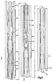
- FIG. 2 (Fig. 2a, 2b, 2c) is a longitudinal section of the packer and service tool;
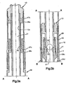
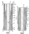
- FIGS. 3a through 3d are fragmentary, longitudinal sections of the portions of the service tool/packer combination designated in brackets in FIG. 2, and includes the portions of the tool which lock the tool in position within the well, form a seal with the well casing, and disconnect the mechanical connection between the service tool and the packer;
- FIGS. 4a and 4b are additional enlarged, fragmentary sections, illustrating the portion of the tool combination indicated in brackets in FIG. 2;
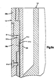
- FIG. 5a is a greatly enlarged, fragmentary, longitudinal section of the structure adjacent to the slips;
- FIG. 5b is a cross section taken along
line 5b-5b of FIG. 3d; - FIG. 5c is a fragmentary, longitudinal section taken along
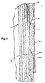
line 5c-5c of FIG. 5b; - FIG. 6a is an enlarged, fragmentary section of the ratchet mechanism for maintaining the slips extended and the seal compressed;
- FIG. 6b is a cross section taken along
line 6b-6b of FIG. 3c; - FIG. 6c is a fragmentary section taken along
line 6c-6c of FIG. 6b, with parts removed for purposes of illustration; - FIG. 7 is an enlarged, fragmentary, longitudinal section illustrating the structural detail of the mechanical connection between the service tool and the packer, along with the fluid pressure-responsive mechanism for releasing such connection; and
- FIG. 8 is a fragmentary roll-out view of the cutter sleeve operable to shear the shear screws which lock the primary valve seat in position.
- FIG. 1 schematically illustrates a
packer 10 andservice tool 13 combination positioned in a well having acasing 19 which has been perforated at 19a adjacent to the formation from which production is to be obtained. When the production formation is above the lower end of the well, asump packer 19b is set within the casing below theperforations 19a to seal off therat hole 19c. Anextension 19d extends from the lower end of the packer to thescreen 19e, through which the oil or gas enters after the packing is completed. During the gravel packing operation, gravel is positioned around thescreen 19e to prevent sand and the like from eroding the screen and to filter sand out of the produced fluids. - FIG. 2 (Fig. 2a, 2b, 2c) illustrate the overall gravel packer/ service tool combination. The
packer 10 is a tubular assembly which extends from an upper end at 11 to a lower end at 12. It includes a number of functioning subassemblies which will be hereinafter designated with a number designation to indicate an overall subassembly, with the individual parts of the subassembly indicated by such reference numeral followed by a letter. - The
service tool 13 is also tubular and telescopes with the packer. The upper end of the service tool 14 is threaded to connect with thework string 15 used to lower the packer/service tool combination into the well to position it for the packing operation. The service tool extends the entire length of the packer to its lower end at 16. Here again, the service tool includes a number of distinct subassemblies, which are also referred to hereinafter by individual reference numerals, with the component parts of the subassembly indicated by such reference numeral followed by a letter designation. - FIGS. 3a through 3d are enlarged, fragmentary, longitudinal sections. The locations of each of the portions of the combination are designated in FIG. 2 (Fig. 2a, 2b, 2c) with brackets. FIGS 4a and 4b are also enlarged, fragmentary, longitudinal sections illustrating the portions of the combination, also indicated in FIG. 2 (Fig. 2a, 2b, 2c) by brackets.
- Before the service tool/packer is lowered into the well, the service tool is positioned within the packer and is mechanically connected by a threaded connection at 17, illustrated in FIG. 3b, so that the service tool and packer are mechanically locked together.
- The various sequential steps of operation of the service tool and packer are performed by fluid pressure-operated subassemblies. These various subassemblies are responsive to differential pressures between the
annulus 18 within thewell casing 19 and the exterior of theservice tool 13 andpacker 10 combination (hereinafter referred to as "annulus pressure") and the pressure within thecentral passage 21 of the tool. Such passage is in communication through the service tool string with the well head and the pressure therein is hereinafter referred to as "tubing pressure." It should be recognized that the absolute pressure in the annulus in the vicinity of the tool is, to a large extent, dependent upon the depth of the tool within the well. Similarly, the absolute pressure within thepassage 21 is a function of the depth of the tool assembly from the well head. The operational functions or steps of operation of the tool combination are determined by the differential pressure between the tubing pressure and the annulus pressure, as discussed in detail below, not upon the absolute pressure. Therefore, in the following specification, references to operating pressures and the like are to differential pressure, not static or absolute pressure. - As the service tool and packer are lowered into the well, the absolute pressure of the tool environment increases gradually until the tool is in the position at the formation in which production is to be achieved. A
check valve 22, best illustrated in FIG. 4b, provides communication between theannulus 18 and anannular passage system 23 which extends up along theservice tool 13 around thecentral passage 21 tolateral ports 24, illustrated in FIG. 3c.Seals lateral passages 24, provide a sealing engagement with the adjacentinner tubing member 28 of thepacker 10 to seal off the upper end of thepassage system 23. - Prior to the lowering of the tool combination into the well, the
passage system 23 above thecheck valve 22 is filled with air. As the tool combination is lowered into the well, the static pressure in the well causes the compression of this air, and ensures that the pressure in thepassage system 23 is raised as the static pressure increases, and is therefore equal to the adjacent annulus pressure when the production formation is reached. Since the practice is to maintain well pressure above the pressure in the formation to control the operation of the well, it is important in the subsequent operation of the tool combination to establish and maintain thepassage system 23 at the annulus pressure which exists prior to the setting and sealing of the packer. Once the packer is set and sealed, the pressure below the check valve will normally return to the lower pressure of the formation. Thecheck valve 22, however, maintains the pressure in the portion of thepassage system 23 immediately below the primary valve seat at the initial annulus pressure. This ensures that excessive differential pressure cannot occur across the primary valve seat during the pressure release of theconnection 17 in the second mode of operation described below. Without the check valve, sufficient differential pressure could occur to cause premature shearing of the shear screws anchoring the primary valve seat. - After the packer is properly positioned in the well at the formation in which production is to be obtained, a first step in the operation of the tool is performed to expand
slips 31 into locking engagement with thewell casing 19. This locks the packer in such location against movement either up or down in the well. Immediately after the slips are extended to lock the packer against the well casing,elastomeric seal 32 is axially compressed and caused to expand radially into tight sealing engagement with the inner surface of the well casing. These operations are performed by establishing a differential pressure between the annulus pressure and the tubing pressure. Therefore, it is necessary to seal off the tubing so that such differential pressure can be established. - A primary
valve seat member 33 is mounted in the service tool above thecheck valve 22. While the tool combination is being lowered into the well, communication is provided between the annulus and the central passage through the primary valve seat bylateral passages 34 in thepacker 10, alignedlateral passages 36 in theservice tool 13 andpassages central passage 21 through a conicalball valve seat 33c. In order to seal off this connection between thecentral passage 21 and theannulus 18, ametal ball 37 is dropped down the service string and is moved by gravity down along thecentral passage 21 into sealing engagement with theball valve seat 33c. FIG. 4a illustrates, in phantom, theball 37 in engagement with the primary valve seat assembly. - Once the
ball 37 is in engagement with the primary ball seat, it is possible to increase the tubing pressure in thecentral passage 21 to a pressure higher than the pressure of theannulus 18, and this pressure differential is utilized to expand theslips 31 into locking engagement with the casing and to then expand theseal 32 into sealing engagement with the casing so that the packer is set and sealed in position. - A fluid pressure-responsive setting and sealing assembly is provided for such operation. The assembly includes an
upper piston 38a and a tandemlower piston 38b mounted in theservice tool 13 around acentral tube 13a. The setting and sealing assembly also includes engagement with the packer at anouter sleeve 39c connected to a threadedring connector 39d, which in turn connects with a lowerouter sleeve 39e of the packer. - Positioned within the lower
outer sleeve 39e is an upperinner sleeve 39f which is connected by aring connector 39g to a lowerinner sleeve 39h which extends inside and past theseal 32. The innerlower sleeve 39h connects at its lower end to aslip expander 39i, providing a conical upper slip expandingcam surface 39j. The packerinner tubing member 28 extends down along the interior of the portion of the setting and the sealing assembly provided by the packer and is connected at its lower end to a lowerslip expander member 28b. Theexpander member 28b provides an upwardly facing, conicalslip expanding surface 28c. The twocamming surfaces slips 31 into tight locking engagement with the well casing. - A first set of shear screws 41 extends through the upper
outer sleeve 39c into acollet sleeve 42 provided by the service tool and locks thesleeves slip expander 39i into the lower end of the lowerinner sleeve 39h, and normally locks such members against relative longitudinal movement. - During the initial operation of setting and sealing, the tubing pressure is increased to a value above the annulus pressure by a first relatively low differential pressure to shear the
screws 41. The tubing pressure is communicated to the twopistons ports 46 in theinner tubing 13a of the service tool. The tubing pressure from theports 46 communicates with anupper piston chamber 47a and alower piston chamber 47b. This first differential pressure created by the elevated tubing pressure results in an axially downward force on the packerouter sleeve 39c, which is resisted by the shear screws 41. - The shear screws 41 are sized so that when the pressure differential reaches such low first differential pressure, the shear screws 41 shear, allowing the
outer sleeve 39c to move relative to the service tool and, in turn, relative to theinner tubing member 28. Such motion is transmitted on down to theslip expander 39i and results in movement of the upper slipexpander cam surface 39j toward the lower slipexpander cam member 28b. This causes radially outward movement of theslips 31. During such movement, the second set of shear screws 43 prevents relative movement between theslip expander 39i and the lowerinner sleeve 39h. Therefore, theseal 32 is not expanded, and merely moves down with the assembly. - The
slips 31 are provided withteeth 31a which bite into the well casing to mechanically lock the packer against movement along the well. The manner in which the slips are supported and aligned, described in greater detail below, provides improved setting of the packer within the well casing. - As the slips are forced out into biting engagement, further movement of the
slip expander 39i is prevented so the differential pressure between the higher tubing pressure and lower annulus pressure increases to a second differential pressure higher than the first differential pressure until the second set of shear screws 43 shear. As soon as the second set of shear screws 43 shears, the lowerinner sleeve 39h moves relative to theslip expander 39i which engages the lower edge of theseal 32. Thering connector 39g, which engages the upper end of the seal, moves toward theslip expander 39i, causing theseal 32 to be axially shortened and radially expanded. This action continues until theseal 32 is radially extended into tight sealing engagement with the well casing to isolate theupper annulus 18a from thelower annulus 18b. - An
improved ratchet assembly 51, best illustrated in FIGS. 6a-6c, includessawtooth ratchet teeth 51a formed along the outer surface of theinner tubing member 28 and aratchet ring 51b formed withinternal ratchet teeth 51c which interengage and mate with theexternal ratchet teeth 51a. As the slips are extended and theseal 32 is extended into sealing engagement with the well casing, theratchet ring 51b is carried down along theinner tubing member 28. The ratchet ring is formed with a slot opening along one side (discussed in greater detail below) which allows the ratchet tooth to cam the ring open as it moves out along theinner ratchet teeth 51a. However, relative movement in the opposite direction is prevented. Therefore, at the completion of the setting and sealing operation, theslips 31 are locked in their extended position and theseal 32 is locked in its expanded and sealing position. - Before proceeding, the locking provided by the
slip 31 and the seal provided by theseal 32 are tested. Alternate tensile and compressive forces are applied through the work string to test the locking of the slips. The function of the seal is tested by raising annulus pressure. A build-up of pressure differential indicates that the sealing is performed. - In some instances, difficulty is encountered in establishing the higher tubing pressure and a back-up mode of operation is provided. Such problem in building up tubing pressure can occur, for example, if scale or rust prevents proper sealing of the
ball 37 in theprimary ball seat 33c. The back-up mode of operation which is employed in the event of an unsuccessful setting and sealing operation utilizing the first mode of operation described above is then initiated. - A secondary valve seat 52 (illustrated in FIG. 3b) is mounted in the service tool above the primary
valve seat assembly 33. The minimum diameter of the secondary valve seat is greater than the diameter of theball 37, so that theball 37 can pass the secondary valve seat and move to the primary valve seat. In the event of failure to operate with the first mode of operation utilizing theball 37, a second ball 53 of larger diameter is dropped down the work string and moves into engagement with thesecondary valve seat 52. This secondary ball 53 is not utilized if theprimary ball 37 properly seats and seals. The ball 53 is usually formed of a phenolic resin or the like, and can be flushed up the well string and out of the well by reverse flow at a subsequent stage in the operation of the tool. After the secondary ball valve 53 is positioned, the slips are extended to set the packer, and theseal 32 is compressed to expand and seal by the application of a tubing pressure which is higher than the annulus pressure, in the same manner described above for the first mode of operation. - After the setting and sealing operation has been completed and successfully tested, the next step in the operation of the packer and service tool combination involves the release of the threaded
mechanical connection 17 between the service tool and the packer so that the service tool can be moved axially relative to the packer. Here again, two modes of operation are provided so that in the event the first mode of operation fails for any reason, a separate and distinct mode of operation is available. - The
mechanical connection 17 between theservice tool 13 and thepacker 10 is best illustrated in FIG. 7. Theconnection 17 is provided by internal threads formed of aninner tubing member 28 of the packer which mate with external threads on thecollet sleeve 42 of the service tool. This threaded connection is a lefthand thread so that in the event the two fluid pressure-responsive modes of operation of the release of the service tool fail, the service tool can be threaded out of the packer by rotation of the service string. - The lower end of the
collet sleeve 42 is provided with longitudinal slots (not illustrated) so that the collet sleeve per se is formed by a plurality of axially extendingfingers 42a having the external threads at the lower ends thereof. Thesefingers 42a are held radially out in mating engagement with the threads on thetubing member 28 by alocking ring 42b positioned within thefingers 42a within the envelope of the threadedconnection 17. - The threaded
connection 17 is released to release the service tool from the packer by moving the lock ring upwardly to a release position in which thefingers 42a can then move radially inward to release the threadedconnection 17. Such movement of thelock ring 42b is provided by apiston 42c connected to thelock ring 42b by a lostmotion connection 42d. The plurality ofshear screws 42e lock thepiston 42c against movement relative to the service tool until the hydraulic release of the service tool is required. These shear screws are sheared by one of the two pressure-responsive modes of operation provided for the release of the service tool. - With the first mode of operation, the tubing pressure within the
central passage 21 is increased above the annulus pressure within theannulus 18a and is communicated to thechamber 42f throughlateral ports 42g. When the differential pressure reaches a third differential pressure higher than the second differential pressure, the shear screws 42e shear, causing upward movement of thepiston 42c. After the piston has moved through the lost motion distance, further movement of thepiston 42c raises thelock ring 42b and allows thefingers 42a to spring inwardly to release the threadedconnection 17 between the service tool and the packer. Thefingers 42a are prestressed so that as soon as the lock ring is moved upwardly, they spring inward to release the threadedconnection 17. - In the event that the threaded
connection 17 fails to release in response to elevated tubing pressure, a second mode of fluid pressure-responsive operation is provided in which the annulus pressure within theupper annulus 18a is increased to a value above the tubing pressure within thepassage 21. When the annulus pressure is raised to a value above the tubing pressure by a third differential pressure, thescrews 42e shear, allowing downward movement of thepiston 42c. This movement, by itself, does not cause release of thelock ring 42b; however, after thescrews 42e have sheared, the piston can be raised by a low differential pressure in which the tubing pressure exceeds the annulus pressure. Such low pressure can be achieved even if sufficient differential pressure cannot be obtained for the first mode of operation to shear thescrews 42e. Therefore, in the second mode of operation, after the shear screws are sheared, the tubing pressure is raised above the annulus pressure to cause upward movement of the piston and release of thelock ring 42b. - In the unlikely event that both the first and second modes of operation for pressure release of the threaded
connection 17 fail, as a third release mode of operation, the service tool can be rotated by the work string to thread the fingers out of the threads on theinner tubing member 28. - If the secondary ball valve 53 has been required and is positioned in the
valve seat 52, reverse circulation is necessary to blow the ball valve 53 up the work string out of the well. For reverse circulation, the service tool is raised to lift the upper seals out of the packer so that fluid pumped down through theupper annulus 18a enters the central passage through thepassages 36 and flows up the tubing to the surface. Such flow carries the secondary ball 53 up out of the well, clearing the tool system for further operations. - The subsequent and last step of operation prior to the actual gravel packing requires the movement of the primary ball seat, with the
primary ball 37 seated therein down until thepassages 36 are open. Here again, two distinct modes of operation are available to ensure the reliability of operation of the tool. The primaryvalve seat assembly 33 is also locked in its normal position illustrated in FIG. 4a by a plurality ofshear screws 33d threaded into a shearscrew receiving ring 33e. As illustrated in the roll-out view of FIG. 8, these screws are in abutment on their upper sides by a downwardly facingflat surface 33f on the primaryvalve seat member 33 and which prevent downward movement of such member until the shear screws 33d are sheared. Positioned below the shear screws is asleeve 33g which is threaded onto the lower end of the primaryvalve seat member 33. The upper ends of thesleeve 33g are formed withgrooves 33h, with onegroove 33h adjacent to each of theshear screws 33d. As best illustrated in FIG. 8, the depth of thegrooves 33h is progressively increased so that in one mode of operation for shearing theshear screws 33d, only a single screw is fractured or sheared at any given time and the shear screws are progressively but singly sheared. - In a first mode of operation, tubing pressure higher than annulus pressure is utilized to shear the
screws 33d to allow downward movement of theprimary valve seat 33. Before the shearing operation is commenced, the service tool is raised a sufficient distance so that theports 24 are raised up past theseals 26 to provide direct communication between theannulus 18a and the portion of thepassage system 23 immediately below the primaryvalve seat member 33. In the first mode of operation, the tubing pressure is again raised to a value above the pressure in the upper annulus (and the passage system 23) until a fourth differential pressure higher than the third differential pressure is reached. At such differential pressure, the shear screws 33d shear and the primaryvalve seat member 33 is carried downwardly until it clears thepassages 36. At such time, the packing operation can be commenced. - In the event that the first mode of operation fails to cause shearing of the shear screws 33d for any reason, a second mode of operation is again provided to release the primary
valve seat member 33 so that it can be moved down clear of thepassages 36. The annulus pressure is then raised above the tubing pressure, producing an upward force on the primary valve seat member. This upward force causes the sleeve to move in an upward direction. - In this instance, only a single shear screw resists such upward movement at any given time, since the shear screw associated with the
groove 33h of least depth is the only shear screw initially engaged. Therefore, the full pressure resultant force in an upward direction is applied to a single shear screw and results in shearing of such screw when the annulus pressure exceeds the tubing pressure by a fifth differential pressure which is substantially lower than the fourth differential pressure. As soon as the first screw shears, the assembly moves up until thegroove 33h, which is slightly greater in length, engages and shears one more shear screw. This action continues progressively until all of the shear screws 33d are sheared, thereby releasing the primaryvalve seat member 33. With this structure, in which the shear screws 33d are progressively sheared rather than simultaneously sheared, the shearing operation to be performed with very low differential pressure compared to the pressure required in the first mode of operation. If desired, the grooves can be structured to simultaneously shear two or more screws. However, in such case, a higher differential pressure is required. Once all of the shear screws have been sheared, the pressure differential is reversed to establish a higher tubing pressure than annulus pressure and a relatively low differential pressure is all that is required to overcome the friction and move the primary valve seat member down clear of thepassages 36. Aratchet ring 33i engages external ratchet teeth to ensure that once the primary valve seat is moved down clear of thepassages 36, it remains in such operating position. - Gravel packing is accomplished by lowering the service tool back until the seals enter the packer so that gravel pumped down along the tubing passes out through the
passages lower annulus 18b. - Once the gravel packing is completed, the service tool is removed and a production tool string is lowered into the well and is connected to the upper end of the packer.
- In some instances, it is necessary to remove a set and sealed packer. When this is necessary, a recovery tool is lowered into the well and connects with the
outer sleeve 39c at its upper end. An upward force is then applied of sufficient magnitude to shear a set ofshear screws 51d, allowing the lowerouter sleeve 39e to move up and cam theratchet ring 51b open out of engagement with theexternal ratchet teeth 51a. FIGS. 6a through 6c best illustrate the structure of theratchet ring 51b and acam 51e, which operates to spread the ratchet ring after the shear screws 51d have sheared. Theratchet ring 51b is formed as a split ring, stressed inwardly to maintain engagement between theexternal ratchet teeth 51a and theinternal ratchet teeth 51c. Thecam 51e is formed on the interior of theouter sleeve 39e and shaped to enter theopening 51f and spread the ring when theouter sleeve 39e is pulled upward by the recovery tool. - The
clearance 51g provided between the outer surface of theratchet ring 51b and the inner surface of theouter sleeve 39e is proportioned with respect to the dimensions of thecam 51e so that the cam spreads the ratchet ring a sufficient amount to ensure that theinternal ratchet teeth 51c clear theexternal ratchet teeth 51a even when theratchet ring 51b moves off center a maximum distance permitted bysuch clearance 51g. The cam, however, is sized so that even when the cam fully spreads the ratchet ring, the diameter of the outer surface of theratchet ring 51b is still less than the diameter of the inner surface of thesleeve 39e. This ensures that jamming does not occur in the event that scale or other debris collects around the ratchet ring during the time the packer is in the well. - Once the ratchet ring releases, the
sleeve 39e is moved upward by the tension applied by the recovery tool and the compression of theseal 39h is released. Similarly, such motion is transmitted to theslip expander 39i, which also moves upwardly to release the slips. As discussed in greater detail below, the slips are retained in aslip retaining ring 31b, which is connected to theslip expander 39i for movement therewith. If the lower ends of the slips fail to release by moving upwardly relative to the lower slip expandingcam member 28b, the upward movement of theslip retainer 31b lifts the slips up and ensures their release. Once the slips are released and the compression in the seal is released, the packer is free to be removed from the well by the recovery tool. - FIGS. 5a through 5c illustrate the structural detail of improved mounting of the
slips 31 and their operating cams. Theslips 31 are formed with a generally U-shape illustrated in FIG. 5b, and providelegs 31d which extend out throughlongitudinal slots 31c in theslip retainer sleeve 31b. Aspring 31e is positioned between thelegs 31d and normally maintains the slips in their retracted position against theinner tubing member 28. - In order to ensure that all of the slips remain retracted while the packer is run down the well, the forward end of the
cam surface 39j is provided with atongue 39k which extends into amating recess 31f in the slips and engages the end of the recess with abutting engagement. This engagement prevents contact between the slips and the casing from causing the slips to expand while the packer is being lowered. However, during the expansion of the packer, the movement of the slips along thesurface 28c tips the recess out from the tongue 38k and allows expansion of the slips. - When the
slips 31 are released for retrieval of the packer from the well, the upward movement of theslip expander 39i causes theslip retainer 31b to engage the lower ends of the slips and ensures that none of the slips hang up on the lower slipexpander cam surface 28c. Such engagement also ensures that the slips do not extend during retrieval of the packer. - With the present invention, the reliability of operation is substantially improved by providing alternate modes of operation for each of the operating steps required in the preparation of the packer for the actual gravel packing. Further, individual subcomponents or combinations are structured for improved reliability in operation. For example, the
check valve 22 prevents premature shearing of the shear screws which lock the primary valve seat in position. The slips are supported and structured for reliable, uniform operation. The shearing of the shear screws locking the primary valve seat in position can be accomplished with low differential pressure in the mode of operation involving an annulus pressure higher than tubing pressure. Further, the ratchet system for holding the slips extended and the seal compressed operates reliably and can be released in a reliable manner when the packer is to be retrieved. - Although the preferred embodiment of this invention has been shown and described, it should be understood that various modifications and rearrangements of the parts may be resorted to within the scope of the appended claims.
Claims (10)
- A packer/service tool combination for gravel packing wells having a well casing comprising a tubular packer (10) having radially extendable slips (31) to lock it in the well casing and a radially deformable seal (32) to establish a seal between the packer (10) and the well casing, a tubular service tool (13) telescoping with the packer (10) and connected by a releasable mechanical connection (17) to the packer (10),a) first fluid pressure-responsive means including a primary ball (37) and primary valve seat (33) to build up a first predetermined tubing pressure and piston means (38a, 38b) operating in response to said first predetermined tubing pressure to extend said slips (31) and said seal (32) for a first operational step of setting the packer,b) second fluid pressure-responsive means for a second operational step of releasing the connection (17),c) and third fluid pressure-responsive means for a third operational step of opening a passage in said service tool to allow gravel packing,said combination being sequentially operable through those operational steps,
characterized in that- said fluid pressure-responsive means provide a first mode of operation for each operational step and a second mode of operation for each operational step,- said first fluid pressure-responsive means includes a second valve seat (52) cooperating with a secondary ball (53) to permit establishment of said predetermined tubing pressure when said primary ball (37) fails to seal with said primary valve seat (33), so that it provides a first and a second mode of operation for said first operational step usable in the event that the related of said first modes of operation fail to function,- said second fluid pressure-responsive means includes a piston (42 b) locked to the service tool by means of shear screws (42c) which are sheared in the first mode of operation by the tubing pressure being increased above the annulus pressure and in the second mode of operation by the annulus pressure being increased above the tubing pressure,- said third fluid pressure-responsive means includes said primary valve seat (33) locked to the service tool by shear screws (33d) which are sheared in the first mode of operation by the tubing pressure being increased above the annulus pressure and in the second mode of operation by the annulus pressure being increased above the tubing pressure. - A packer/service tool combination according to claim 1, characterized in that it comprises passages and ports (21), (23), (24), (46) allowing either the creation of a differential "tubing pressure", or of an "annulus pressure", or of both in multiple sequences.
- A packer/service tool combination according to claim 1 or 2, characterized in that said second and third fluid pressure-responsible means comprise shear means (33d, 42e) operable to sequentially shear in response to "tubing pressure" and/or "annulus pressure" so as to allow the said connection (17) and ball seat (33) to move and/or be released in sequence.
- A packer/service tool combination as set forth in claim 1, wherein shear elements are provided to prevent said seal from deforming into sealing engagement with said casing until after said slips are radially extended.
- A packer/service tool combination as set forth in claim 1, wherein said slips (31) and piston means (38a, 38b) provide camming surfaces (39j) which engage to radially expand said slips (31), and abutting means prevent expansion of said slips (31) while said combination is lowered along said casing.
- A packer/service tool combination as set forth in claim 5, wherein said abutting means includes a tongue extending into a recess in said slips.
- A packer/service tool combination as set forth in claim 1, wherein means are provided to prevent radial expansion of said slips during insertion and retrieval of said combination.
- A packer/service tool combination as set forth in claim 1, wherein said combination is sequentially operable through a plurality of operational steps in response to progressively higher pressure differentials between the annulus pressure between said combination and a well casing and the tubing pressure within said service tool, and further comprises a plurality of sets of shear elements sheared in sequence at progressively higher differential pressures between said annulus pressure and said tubing pressure to initiate said operational steps, at least one of said sets of shear elements being operable to withstand without shearing a first predetermined differential pressure in which the tubing pressure exceeds the annulus pressure and being sheared by a substantially lower differential pressure when said annulus pressure exceeds said tubing pressure.
- A method of gravel packing a subterranean well, characterized in that it comprises the lowering of a packer and service tool combination according to anyone of claims 1 to 8 into said well location requiring gravel packing, and using in each one of steps a), b) and c), said second mode of operation in the event said first mode of operation fails.
- A method as set forth in claim 9, including providing a primary valve seat (33) and a primary ball valve, to permit pressure build-up in said first mode of operation, and providing a secondary valve seat (52) and secondary ball valve to permit pressure build-up for said second mode of operation.
Applications Claiming Priority (2)
| Application Number | Priority Date | Filing Date | Title |
|---|---|---|---|
| US07/478,377 US5069280A (en) | 1990-02-12 | 1990-02-12 | Gravel packer and service tool |
| US478377 | 1995-06-07 |
Publications (3)
| Publication Number | Publication Date |
|---|---|
| EP0446976A2 EP0446976A2 (en) | 1991-09-18 |
| EP0446976A3 EP0446976A3 (en) | 1992-03-18 |
| EP0446976B1 true EP0446976B1 (en) | 1997-04-23 |
Family
ID=23899691
Family Applications (1)
| Application Number | Title | Priority Date | Filing Date |
|---|---|---|---|
| EP91200260A Expired - Lifetime EP0446976B1 (en) | 1990-02-12 | 1991-02-08 | Gravel packer and service tool |
Country Status (6)
| Country | Link |
|---|---|
| US (1) | US5069280A (en) |
| EP (1) | EP0446976B1 (en) |
| AU (2) | AU7082991A (en) |
| BR (1) | BR9100564A (en) |
| DE (1) | DE69125746D1 (en) |
| NO (1) | NO910541L (en) |
Cited By (1)
| Publication number | Priority date | Publication date | Assignee | Title |
|---|---|---|---|---|
| WO2019168505A1 (en) * | 2018-02-27 | 2019-09-06 | Halliburton Energy Services, Inc. | Downhole check valve assembly with a swellable element mechanism |
Families Citing this family (35)
| Publication number | Priority date | Publication date | Assignee | Title |
|---|---|---|---|---|
| US5244044A (en) * | 1992-06-08 | 1993-09-14 | Otis Engineering Corporation | Catcher sub |
| US5377749A (en) * | 1993-08-12 | 1995-01-03 | Barbee; Phil | Apparatus for setting hydraulic packers and for placing a gravel pack in a downhole oil and gas well |
| US5975205A (en) * | 1997-09-30 | 1999-11-02 | Carisella; James V. | Gravel pack apparatus and method |
| WO2000005484A1 (en) * | 1998-07-22 | 2000-02-03 | Baker Hughes Incorporated | Apparatus and method for open hole gravel packing |
| US6382319B1 (en) * | 1998-07-22 | 2002-05-07 | Baker Hughes, Inc. | Method and apparatus for open hole gravel packing |
| US6789623B2 (en) | 1998-07-22 | 2004-09-14 | Baker Hughes Incorporated | Method and apparatus for open hole gravel packing |
| US6575246B2 (en) | 1999-04-30 | 2003-06-10 | Schlumberger Technology Corporation | Method and apparatus for gravel packing with a pressure maintenance tool |
| US6220353B1 (en) * | 1999-04-30 | 2001-04-24 | Schlumberger Technology Corporation | Full bore set down tool assembly for gravel packing a well |
| US6237687B1 (en) * | 1999-06-09 | 2001-05-29 | Eclipse Packer Company | Method and apparatus for placing a gravel pack in an oil and gas well |
| US6464002B1 (en) | 2000-04-10 | 2002-10-15 | Weatherford/Lamb, Inc. | Whipstock assembly |
| GB0026904D0 (en) * | 2000-11-03 | 2000-12-20 | Omega Completion Technology | Setting tool for use in a wellbore |
| US6491097B1 (en) | 2000-12-14 | 2002-12-10 | Halliburton Energy Services, Inc. | Abrasive slurry delivery apparatus and methods of using same |
| EP1712730B1 (en) * | 2001-05-18 | 2010-12-15 | Dril-Quip, Inc. | Ball and plug dropping head |
| US6814143B2 (en) * | 2001-11-30 | 2004-11-09 | Tiw Corporation | Downhole tubular patch, tubular expander and method |
| US7051805B2 (en) * | 2001-12-20 | 2006-05-30 | Baker Hughes Incorporated | Expandable packer with anchoring feature |
| US7661470B2 (en) | 2001-12-20 | 2010-02-16 | Baker Hughes Incorporated | Expandable packer with anchoring feature |
| US7128152B2 (en) * | 2003-05-21 | 2006-10-31 | Schlumberger Technology Corporation | Method and apparatus to selectively reduce wellbore pressure during pumping operations |
| US7296624B2 (en) * | 2003-05-21 | 2007-11-20 | Schlumberger Technology Corporation | Pressure control apparatus and method |
| US7080693B2 (en) * | 2003-10-14 | 2006-07-25 | Baker Hughes Incorporated | Retrievable packer assembly, method, and system with releasable body lock ring |
| US7828056B2 (en) * | 2007-07-06 | 2010-11-09 | Schlumberger Technology Corporation | Method and apparatus for connecting shunt tubes to sand screen assemblies |
| US8511380B2 (en) * | 2007-10-10 | 2013-08-20 | Schlumberger Technology Corporation | Multi-zone gravel pack system with pipe coupling and integrated valve |
| CA2637519C (en) * | 2008-04-01 | 2011-07-12 | Packers Plus Energy Services Inc. | Hydraulically openable ported sub |
| US9033041B2 (en) * | 2011-09-13 | 2015-05-19 | Schlumberger Technology Corporation | Completing a multi-stage well |
| US9752407B2 (en) | 2011-09-13 | 2017-09-05 | Schlumberger Technology Corporation | Expandable downhole seat assembly |
| US10364629B2 (en) | 2011-09-13 | 2019-07-30 | Schlumberger Technology Corporation | Downhole component having dissolvable components |
| US9528336B2 (en) | 2013-02-01 | 2016-12-27 | Schlumberger Technology Corporation | Deploying an expandable downhole seat assembly |
| US10487625B2 (en) | 2013-09-18 | 2019-11-26 | Schlumberger Technology Corporation | Segmented ring assembly |
| US9644452B2 (en) | 2013-10-10 | 2017-05-09 | Schlumberger Technology Corporation | Segmented seat assembly |
| US9689241B2 (en) | 2014-11-26 | 2017-06-27 | General Electric Company | Gas lift valve assemblies having fluid flow barrier and methods of assembling same |
| US9765603B2 (en) | 2014-11-26 | 2017-09-19 | General Electric Company | Gas lift valve assemblies and methods of assembling same |
| NO342097B1 (en) | 2014-12-05 | 2018-03-19 | Interwell Technology As | Detachable locking device |
| US20170037697A1 (en) * | 2015-08-06 | 2017-02-09 | Baker Hughes Incorporated | Interventionless Packer Setting Tool |
| US10538988B2 (en) | 2016-05-31 | 2020-01-21 | Schlumberger Technology Corporation | Expandable downhole seat assembly |
| CN109577906B (en) * | 2017-09-29 | 2021-07-02 | 中国石油天然气股份有限公司 | Packer |
| CN112282689B (en) * | 2020-11-02 | 2023-04-07 | 中国石油天然气股份有限公司 | Soluble packer and using method thereof |
Family Cites Families (12)
| Publication number | Priority date | Publication date | Assignee | Title |
|---|---|---|---|---|
| US3145777A (en) * | 1962-08-06 | 1964-08-25 | Cicero C Brown | Combination hydraulic and weight-set dual string well packers |
| US4187906A (en) * | 1978-05-08 | 1980-02-12 | Baker International Corporation | Well bore apparatus with annulus pressure releasable tubing seal unit |
| US4190107A (en) * | 1978-08-25 | 1980-02-26 | Baker International Corporation | Well bore apparatus with hydraulically releasable tubing seal unit |
| US4345649A (en) * | 1980-09-05 | 1982-08-24 | Hughes Tool Company | Well packer |
| US4541486A (en) * | 1981-04-03 | 1985-09-17 | Baker Oil Tools, Inc. | One trip perforating and gravel pack system |
| US4441559A (en) * | 1982-11-17 | 1984-04-10 | Hughes Tool Company | Retrievable well packer |
| US4526229A (en) * | 1983-02-14 | 1985-07-02 | Gulf Oil Corporation | Hydraulic packer assembly |
| US4862957A (en) * | 1985-09-11 | 1989-09-05 | Dowell Schlumberger Incorporated | Packer and service tool assembly |
| US4660637A (en) * | 1985-09-11 | 1987-04-28 | Dowell Schlumberger Incorporated | Packer and service tool assembly |
| US4726419A (en) * | 1986-02-07 | 1988-02-23 | Halliburton Company | Single zone gravel packing system |
| US4813486A (en) * | 1987-09-23 | 1989-03-21 | Arrow Oil Tools, Inc. | Retractable slip assembly |
| US4858691A (en) * | 1988-06-13 | 1989-08-22 | Baker Hughes Incorporated | Gravel packing apparatus and method |
-
1990
- 1990-02-12 US US07/478,377 patent/US5069280A/en not_active Expired - Fee Related
-
1991
- 1991-02-06 AU AU70829/91A patent/AU7082991A/en not_active Abandoned
- 1991-02-08 BR BR919100564A patent/BR9100564A/en not_active IP Right Cessation
- 1991-02-08 EP EP91200260A patent/EP0446976B1/en not_active Expired - Lifetime
- 1991-02-08 DE DE69125746T patent/DE69125746D1/en not_active Expired - Lifetime
- 1991-02-11 NO NO91910541A patent/NO910541L/en unknown
-
1993
- 1993-06-24 AU AU41481/93A patent/AU649387B2/en not_active Ceased
Cited By (3)
| Publication number | Priority date | Publication date | Assignee | Title |
|---|---|---|---|---|
| WO2019168505A1 (en) * | 2018-02-27 | 2019-09-06 | Halliburton Energy Services, Inc. | Downhole check valve assembly with a swellable element mechanism |
| GB2582501A (en) * | 2018-02-27 | 2020-09-23 | Halliburton Energy Services Inc | Downhole check valve assembly with a swellable element mechanism |
| GB2582501B (en) * | 2018-02-27 | 2022-05-18 | Halliburton Energy Services Inc | Downhole check valve assembly with a swellable element mechanism |
Also Published As
| Publication number | Publication date |
|---|---|
| BR9100564A (en) | 1991-10-29 |
| NO910541L (en) | 1991-08-13 |
| EP0446976A2 (en) | 1991-09-18 |
| AU7082991A (en) | 1991-08-29 |
| EP0446976A3 (en) | 1992-03-18 |
| NO910541D0 (en) | 1991-02-11 |
| DE69125746D1 (en) | 1997-05-28 |
| AU649387B2 (en) | 1994-05-19 |
| US5069280A (en) | 1991-12-03 |
| AU4148193A (en) | 1993-08-26 |
Similar Documents
| Publication | Publication Date | Title |
|---|---|---|
| US5069280A (en) | Gravel packer and service tool | |
| AU759686B2 (en) | Method and apparatus for top to bottom expansion of tubulars | |
| AU2004282568B2 (en) | Retrievable packer assembly and system with releaseable body locking ring | |
| US4660637A (en) | Packer and service tool assembly | |
| US4862957A (en) | Packer and service tool assembly | |
| US4311195A (en) | Hydraulically set well packer | |
| EP0589586B1 (en) | Isolation washpipe for earth well completions and method for use in gravel packing a well | |
| US4862966A (en) | Liner hanger with collapsible ball valve seat | |
| CA1303976C (en) | Method for installing a liner within a well bore | |
| US4487258A (en) | Hydraulically set well packer | |
| US3659647A (en) | Well packer | |
| US5404955A (en) | Releasable running tool for setting well tool | |
| EP1712731B1 (en) | Liner hanger, running tool and method | |
| GB2138055A (en) | Hydraulic running and setting tool for well packer | |
| EP3914805B1 (en) | Expandable liner hanger system and methodology | |
| US20070144735A1 (en) | Apparatus for radially expanding and plastically deforming a tubular member | |
| US5360069A (en) | Failsafe liner installation assembly and method | |
| US5146994A (en) | Packing assembly for use with reeled tubing and method of operating and removing same | |
| CN117468885A (en) | A high-pressure packer and its unpacking method | |
| US4413677A (en) | Dual string well packer | |
| US4972908A (en) | Packer arrangement | |
| US5000265A (en) | Packing assembly for use with reeled tubing and method of operating and removing same | |
| CN113454311A (en) | Top-setting plug and method | |
| GB2280461A (en) | Hydraulically set packer | |
| CN111757972B (en) | Method and apparatus for transferring loads within a cut-unset packer |
Legal Events
| Date | Code | Title | Description |
|---|---|---|---|
| PUAI | Public reference made under article 153(3) epc to a published international application that has entered the european phase |
Free format text: ORIGINAL CODE: 0009012 |
|
| AK | Designated contracting states |
Kind code of ref document: A2 Designated state(s): DE DK FR GB IT NL |
|
| PUAL | Search report despatched |
Free format text: ORIGINAL CODE: 0009013 |
|
| AK | Designated contracting states |
Kind code of ref document: A3 Designated state(s): DE DK FR GB IT NL |
|
| 17P | Request for examination filed |
Effective date: 19920828 |
|
| 17Q | First examination report despatched |
Effective date: 19921230 |
|
| RAP1 | Party data changed (applicant data changed or rights of an application transferred) |
Owner name: SOFITECH N.V. Owner name: COMPAGNIE DES SERVICES DOWELL SCHLUMBERGER |
|
| RIN1 | Information on inventor provided before grant (corrected) |
Inventor name: BROOKEY, ROBERT L. Inventor name: MCKEE, L. MICKAEL Inventor name: GURLEY, DERREL Inventor name: SCRANTON, JOSEPH D. Inventor name: SODICH, ERNIE |
|
| GRAG | Despatch of communication of intention to grant |
Free format text: ORIGINAL CODE: EPIDOS AGRA |
|
| GRAH | Despatch of communication of intention to grant a patent |
Free format text: ORIGINAL CODE: EPIDOS IGRA |
|
| GRAH | Despatch of communication of intention to grant a patent |
Free format text: ORIGINAL CODE: EPIDOS IGRA |
|
| GRAH | Despatch of communication of intention to grant a patent |
Free format text: ORIGINAL CODE: EPIDOS IGRA |
|
| GRAA | (expected) grant |
Free format text: ORIGINAL CODE: 0009210 |
|
| AK | Designated contracting states |
Kind code of ref document: B1 Designated state(s): DE DK FR GB IT NL |
|
| PG25 | Lapsed in a contracting state [announced via postgrant information from national office to epo] |
Ref country code: IT Free format text: LAPSE BECAUSE OF FAILURE TO SUBMIT A TRANSLATION OF THE DESCRIPTION OR TO PAY THE FEE WITHIN THE PRE;WARNING: LAPSES OF ITALIAN PATENTS WITH EFFECTIVE DATE BEFORE 2007 MAY HAVE OCCURRED AT ANY TIME BEFORE 2007. THE CORRECT EFFECTIVE DATE MAY BE DIFFERENT FROM THE ONE RECORDED.SCRIBED TIME-LIMIT Effective date: 19970423 Ref country code: NL Effective date: 19970423 Ref country code: FR Effective date: 19970423 Ref country code: DK Effective date: 19970423 |
|
| REF | Corresponds to: |
Ref document number: 69125746 Country of ref document: DE Date of ref document: 19970528 |
|
| PG25 | Lapsed in a contracting state [announced via postgrant information from national office to epo] |
Ref country code: DE Effective date: 19970724 |
|
| EN | Fr: translation not filed | ||
| NLV1 | Nl: lapsed or annulled due to failure to fulfill the requirements of art. 29p and 29m of the patents act | ||
| PLBE | No opposition filed within time limit |
Free format text: ORIGINAL CODE: 0009261 |
|
| STAA | Information on the status of an ep patent application or granted ep patent |
Free format text: STATUS: NO OPPOSITION FILED WITHIN TIME LIMIT |
|
| 26N | No opposition filed | ||
| PGFP | Annual fee paid to national office [announced via postgrant information from national office to epo] |
Ref country code: GB Payment date: 20010104 Year of fee payment: 11 |
|
| REG | Reference to a national code |
Ref country code: GB Ref legal event code: IF02 |
|
| PG25 | Lapsed in a contracting state [announced via postgrant information from national office to epo] |
Ref country code: GB Free format text: LAPSE BECAUSE OF NON-PAYMENT OF DUE FEES Effective date: 20020208 |
|
| GBPC | Gb: european patent ceased through non-payment of renewal fee |
Effective date: 20020208 |