EP0446635B1 - Scroll-type fluid machinery - Google Patents
Scroll-type fluid machinery Download PDFInfo
- Publication number
- EP0446635B1 EP0446635B1 EP91102022A EP91102022A EP0446635B1 EP 0446635 B1 EP0446635 B1 EP 0446635B1 EP 91102022 A EP91102022 A EP 91102022A EP 91102022 A EP91102022 A EP 91102022A EP 0446635 B1 EP0446635 B1 EP 0446635B1
- Authority
- EP
- European Patent Office
- Prior art keywords
- scroll
- wrap
- stationary
- orbiting scroll
- orbiting
- Prior art date
- Legal status (The legal status is an assumption and is not a legal conclusion. Google has not performed a legal analysis and makes no representation as to the accuracy of the status listed.)
- Expired - Lifetime
Links
- 239000012530 fluid Substances 0.000 title claims description 22
- 238000007789 sealing Methods 0.000 description 26
- 230000006835 compression Effects 0.000 description 16
- 238000007906 compression Methods 0.000 description 16
- 230000002093 peripheral effect Effects 0.000 description 13
- 238000003754 machining Methods 0.000 description 5
- 239000004519 grease Substances 0.000 description 4
- 238000000034 method Methods 0.000 description 3
- 238000009826 distribution Methods 0.000 description 2
- 239000000314 lubricant Substances 0.000 description 2
- 239000000463 material Substances 0.000 description 2
- 230000013011 mating Effects 0.000 description 2
- 238000010276 construction Methods 0.000 description 1
- 238000006073 displacement reaction Methods 0.000 description 1
- 230000000694 effects Effects 0.000 description 1
- 238000005304 joining Methods 0.000 description 1
- 239000012858 resilient material Substances 0.000 description 1
- 239000000565 sealant Substances 0.000 description 1
- 238000004904 shortening Methods 0.000 description 1
- 239000007787 solid Substances 0.000 description 1
- 230000007306 turnover Effects 0.000 description 1
Images



Classifications
-
- F—MECHANICAL ENGINEERING; LIGHTING; HEATING; WEAPONS; BLASTING
- F01—MACHINES OR ENGINES IN GENERAL; ENGINE PLANTS IN GENERAL; STEAM ENGINES
- F01C—ROTARY-PISTON OR OSCILLATING-PISTON MACHINES OR ENGINES
- F01C1/00—Rotary-piston machines or engines
- F01C1/02—Rotary-piston machines or engines of arcuate-engagement type, i.e. with circular translatory movement of co-operating members, each member having the same number of teeth or tooth-equivalents
- F01C1/0207—Rotary-piston machines or engines of arcuate-engagement type, i.e. with circular translatory movement of co-operating members, each member having the same number of teeth or tooth-equivalents both members having co-operating elements in spiral form
- F01C1/0246—Details concerning the involute wraps or their base, e.g. geometry
-
- F—MECHANICAL ENGINEERING; LIGHTING; HEATING; WEAPONS; BLASTING
- F01—MACHINES OR ENGINES IN GENERAL; ENGINE PLANTS IN GENERAL; STEAM ENGINES
- F01C—ROTARY-PISTON OR OSCILLATING-PISTON MACHINES OR ENGINES
- F01C1/00—Rotary-piston machines or engines
- F01C1/02—Rotary-piston machines or engines of arcuate-engagement type, i.e. with circular translatory movement of co-operating members, each member having the same number of teeth or tooth-equivalents
- F01C1/0207—Rotary-piston machines or engines of arcuate-engagement type, i.e. with circular translatory movement of co-operating members, each member having the same number of teeth or tooth-equivalents both members having co-operating elements in spiral form
- F01C1/0215—Rotary-piston machines or engines of arcuate-engagement type, i.e. with circular translatory movement of co-operating members, each member having the same number of teeth or tooth-equivalents both members having co-operating elements in spiral form where only one member is moving
- F01C1/0223—Rotary-piston machines or engines of arcuate-engagement type, i.e. with circular translatory movement of co-operating members, each member having the same number of teeth or tooth-equivalents both members having co-operating elements in spiral form where only one member is moving with symmetrical double wraps
-
- F—MECHANICAL ENGINEERING; LIGHTING; HEATING; WEAPONS; BLASTING
- F01—MACHINES OR ENGINES IN GENERAL; ENGINE PLANTS IN GENERAL; STEAM ENGINES
- F01C—ROTARY-PISTON OR OSCILLATING-PISTON MACHINES OR ENGINES
- F01C19/00—Sealing arrangements in rotary-piston machines or engines
- F01C19/08—Axially-movable sealings for working fluids
-
- F—MECHANICAL ENGINEERING; LIGHTING; HEATING; WEAPONS; BLASTING
- F04—POSITIVE - DISPLACEMENT MACHINES FOR LIQUIDS; PUMPS FOR LIQUIDS OR ELASTIC FLUIDS
- F04C—ROTARY-PISTON, OR OSCILLATING-PISTON, POSITIVE-DISPLACEMENT MACHINES FOR LIQUIDS; ROTARY-PISTON, OR OSCILLATING-PISTON, POSITIVE-DISPLACEMENT PUMPS
- F04C2250/00—Geometry
- F04C2250/10—Geometry of the inlet or outlet
- F04C2250/102—Geometry of the inlet or outlet of the outlet
-
- F—MECHANICAL ENGINEERING; LIGHTING; HEATING; WEAPONS; BLASTING
- F05—INDEXING SCHEMES RELATING TO ENGINES OR PUMPS IN VARIOUS SUBCLASSES OF CLASSES F01-F04
- F05B—INDEXING SCHEME RELATING TO WIND, SPRING, WEIGHT, INERTIA OR LIKE MOTORS, TO MACHINES OR ENGINES FOR LIQUIDS COVERED BY SUBCLASSES F03B, F03D AND F03G
- F05B2250/00—Geometry
- F05B2250/50—Inlet or outlet
- F05B2250/502—Outlet
Definitions
- This invention relates to a scroll-type fluid machinery functioning compressors, expanders or vacuum pumps, and more particularly to a twin unit scroll-type fluid machinery having stationary scrolls axially disposed on both surfaces of an orbiting scroll.
- Scroll-type compressors are known in the art which comprise: a stationary scroll having a first wrap formed in an involute spiral located within a casing which encloses all members thereof with a peripheral wall provided with a suction port and an exhaust port respectively at a peripheral region and a central region thereof, an orbiting scroll having a second wrap formed also in the involute spiral mating with the first wrap at least in a pair of line contacts forming a pocket between the line contacts of the first and second wraps, wherein, during the orbiting scroll is driven with an orbital movement rather than a rotational movement, air is taken through the suction port into the pocket the volume of which is reduced as it moves along the scroll surfaces to the central region, the compressed air is discharged through the exhaust port.
- Pat. No. 4,129,405 a kind of devices referred as a single unit scroll-type machinery for expanding, compressing or displacing fluid with a stationary scroll and an orbiting scroll interfitting each other, and is disclosed in U.S. Pat. No. 4,192,152, and Japanese Patent Publication 63-42081 another kind of devices referred to as a twin unit scroll-type machinery for expanding, compressing or displacing fluid with a pair of stationary scrolls having respectively a wrap inside and with an orbiting scroll having each wrap on both surfaces which are interfitted respectively with the stationary scrolls mating with the wraps.
- suction port there has to be provided another suction port at a 180 degree apart from the first suction port, where each beginning end of the wraps contacts respectively with other wrap side walls forming one of the utmost contact lines of the pockets, or has to provide a half-way detour passage circumferentially around the peripheral of the wraps connecting the suction port with other side of contact line 180 degrees apart therefrom, resulting in the machinery being large in size and sophisticated in machining and assembling processes.
- the two suction ports further, means two pockets at a 180 degree apart which is hard to be simultaneously compressed requiring a double power, and reduces an intake efficiency because the fluid volume of the fluid sucked in the pockets is limited by the port area and the detour passage.
- the issue in the region of the exhaust port resides in the volume of the pockets at the central portion where an eccentric shaft has to be provided axially parallel with a drive shaft to drive the orbiting scroll together with a bearing thereof, where the exhaust port and a terminal wrap end have to be provided at the peripheral circumference of the bearing, wherein the involute spiral terminates before reaching the center thereof without shortening its length for more smaller pocket volume because there has to be disposed a pair of terminal wrap ends 180 degrees apart.
- the conventional machineries result in the pocket volume to be released at the exhaust port remaining as large as not to attain a maximum compression ratio. What is worse, the greater volume of the pocket at the last stage makes the sealing line longer, and makes the leakage easier resulting in that a higher compression efficiency is not attainable.
- a constitution may be provided wherein a main shaft to drive an orbiting scroll is disposed at the back surface thereof, and an exhaust port is provided at the center of a stationary scroll.
- the main shaft to drive the orbiting scroll has to be disposed through the stationary scrolls at the center thereof, because the orbiting scroll has to be oppositely interfitted with the stationary scrolls so as to arrange a pair of stationary scrolls at both sides of the orbiting scroll, wherein the failures are inherent urging the constitution that the exhaust port and the terminal wrap ends have to be disposed at the peripheral circumference of the bearing where the involute spiral terminates before reaching close to the center thereof.
- a plurality of thrust adjusting means is provided to solve the issue in either scroll-type machineries at the peripheral wall of the stationary scroll opposing the orbiting scroll, the wall of which is located outside the wrap space where the compression is effected, three set in a 120 degree distribution for example, whereby the parallel alignment of the scrolls and the thrust adjustment is subjected.
- the twin unit scroll-type machinery above is formed in a constitution that the orbiting scroll is interfitted with a pair of stationary scrolls at both sides, the thrust adjusting means are provided at each of stationary scrolls to adjust the thrust through the orbiting scroll commonly held at both sides thereof.
- the thrust adjusting means are provided at each of stationary scrolls to adjust the thrust through the orbiting scroll commonly held at both sides thereof.
- the scrolls are intended to be precisely assembled in a unit with bearings, a casing and so forth, to avoid the deviations of the scrolls from being parallel to each other, and the misalignment of the thrust.
- the constitution of the three scrolls with the main shaft and the eccentric axes assembled in one unit with a plurality of parallel axes does not allow the orbiting scroll to have the slightest axial deviation. Even if the deviation may be allowed within some extent, it brings another failure that the tolerance may require further an extra axis power.
- twin unit scroll-type fluid machinery has been believed to have such a great advantage as to form it small in size allowing the compression procedure at both sides of the orbiting scroll, and a two stage compressor with a higher compression ratio, hence, with a better power efficiency, the twin unit machinery has not been realized successfully because of the troublesome issues said above.
- Scroll-type fluid machines having two scrolls with respective wraps being engaged with a 180° phase difference are also disclosed in DE-A-2 160 582 and EP-A-0 298 315. For all these machines, one wrap is longer than the other wrap by at least half a turn extending inwardly.
- a preferred embodiment of the present invention provides a scroll-type fluid machinery with an advanced sealing means and an advanced compression efficiency or expansion efficiency.
- Another embodiment of the present invention provides a scroll-type fluid machinery, particularly in a twin unit machinery with a reasonable tolerance in an assembly alignment and a machining deviation range not so strict as it used to be, wherein the tolerance is absorbed to maintain the tangential sealing between the wraps, and the radial sealing between the scroll ends and the mirror wall surfaces opposing thereto so as to attain the compression efficiency or the expansion efficiency desired.
- Yet another embodiment of the present invention provides a scroll-type machinery, capable of precise self-alignment in parallel, capable of self-adjustment of the distance between the scrolls, during the orbit movement thereof.
- Still another embodiment of the present invention provides a scroll-type fluid machinery, absorbing precisely an axial misalignment of the orbiting scroll, capable of compression or expanding as desired without increasing the axis power unnecessarily.
- a stationary scroll wrap extends approximately another half turn relative to a wrap of the orbiting scroll toward the peripheral region, instead as in the conventional one, so that wraps with the same turns are engaged 180 degrees apart, wherein each of the wraps of the stationary scroll and the orbiting scroll is able to contact nearly end to end during the orbit movement of the orbiting scroll.
- the present invention is applicable not only to the twin unit as above, but also to a single unit scroll-type fluid machinery having a stationary scroll which is disposed with a main shaft at the center thereof.
- a constitution reverse to the above may also be possible, that is, to form the wrap of the orbiting scroll longer more than a half turn than that of the wrap of the stationary scroll.
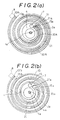
- FIGS. 1 and 2 the function of the present invention will be described separately on the suction portion of the compressor hereinafter.
- the suction portion at the peripheral region firstly, because an external wrap end(10b) of stationary scroll(2) is extended a half turn over that of the orbiting scroll, the wrap ends(10b, 15b) come in contact with each other whereat a suction port(8) is provided.
- the single port(8) instead of providing two suction ports located 180° apart, or instead of providing a detour passage between contacting lines 180 degrees apart as in the conventional one, allows the machinery to be small in size and to save the machining steps.
- the first pocket(30B) between the first and the next contact lines becomes greater than the conventional one, because the external wrap end(10b) of the stationary scroll(2) is extended by 180 degrees, which increases the intake efficiency as well.
- the single pocket(30B) for the initial intake through the single suction port(8) with a greater volume than the divided volume into two pockets as in the conventional one is continuously compressed reducing the volume from the suction portion to the exhaust portion, whereby it makes the machinery possible to increase the compression ratio and the exhaust pressure, too.
- an internal wrap end (10a) of stationary scroll(2) is extended half a turn relative to an internal wrap end(15a) of the orbiting scroll (1) in an involute spiral toward the peripheral of the bearing to form in a constitution in which the internal wrap ends(10a, 15a) come to contact with nearly end to end alignment during the orbit movement of the orbiting scroll (1), whereby the final stage of the pocket(30A) becomes the smallest volume, and hence, the advanced exhaust efficiency and the higher compression ratio can be achieved (FIGS. 1 and 2(a)).
- the internal wrap end(15a) of the orbiting scroll(1) is disposed at the dead end(21a) of the scroll groove(21) of the stationary scroll between the peripheral circumference wall(4a) of the bank(4) forming the central axis hole(2a) and a wrap (10c) next to the wrap(10a) thereof, the dead end wall(21a) of the scroll groove (21) being formed in an arc of a half circle with which the internal wrap end (15a) of the orbiting scroll (1) is slidably in contact, whereby the sealing between the internal wrap end(15a) and the dead end wall(21a) of the wrap groove(12) is secured.
- the dead end wall(21a) of the scroll groove(21) in the arc of a half circle with a radius (X) almost the same as to the distance of the eccentricity - a distance between the center(la) of axis hole for the orbiting scroll(1) and the center(2a) of axis hole for the stationary scroll(2), or in other words, an orbiting radius(x).
- an exhaust port(7) is provided at the dead end wall(21a) of the scroll groove to discharge the fluid, wherein the final stage of the pocket is in the smallest volume to secure the compression efficiency.
- the pocket at the final stage in a smaller volume provides a shorter sealing line which assures a better sealing effect, and prevents a returning flow of the fluid, resulting in further improving the compression efficiency.
- the constitution above provides the improved intake/exhaust efficiency at either sides of suction port(8) and exhaust port and a better sealing performance.
- the feature does not realize, if the scrolls are not disposed in parallel if the distances between them are not kept precisely, and if those alignments are not adjustable easily.
- a twin unit scroll-type fluid machinery which comprises: an orbiting scroll (1) disposed with a main shaft(5) axially movable relative to stationary scrolls(2A, 2B) within a short distance, a sealing member(9) disposed at least in a groove at the wrap ends (101, 151) of the orbiting scroll(1) resiliently enforced evenly against mirror surfaces(11a, 21a) of the stationary scrolls(2A, 2B), wherein the interfaces between the mirror surfaces and the wrap ends(101, 151) are formed capable to be sealed with the sealing member(9).
- the means for resiliently enforcing evenly the sealing member(9) may be realized with either sealing member(9) made of a resilient material as in an enlarged drawing FIG. 3(a), or with a sealing member(9) with a resilient member (91) disposed in a seal groove (90) of the wrap end as in FIG. 3(b).
- the invention above because the orbiting scroll(1) is axially movable within the desired distance, and because the sealing members(9) are inserted in the groove at the wrap ends(101, 151) of the orbiting scroll(1) uniformly urged to the oppose mirror surfaces(lla, 21a), provides a feature that a thrust force on the interface due to the machining deviation and misalignment in the assembly process are compensated with the resilient force of the member, and thus, the self-alignment can be achieved.
- the sealing member(9) is elastic or is variable in length, the sealing member(9) easily absorbs the axial deviation of the orbiting scroll (1).
- FIGS. 1 and 2 are top plan sectional views of one set of wraps showing their schematic forms and constitutions constructed in accordance with the present invention.
- FIG. 3 is a longitudinal sectional view of a twin unit scroll-type fluid machinery in which FIGS. 3(a) and 3(b) are longitudinal cross sectional detailed views of a portion of sealing members.
- FIG. 4 is a partial longitudinal section view showing a portion of center axis.
- FIG. 5 is a partial longitudinal section view showing a portion of orbiting shaft.
- FIGS. 1 and 2 are views showing wraps of a scroll-type compressor.
- reference numeral (10) indicates a wrap formed inside a stationary scroll(2A or 2B), formed as a spiral involute of 3-3/4 turns started from a peripheral wall(4a) of a bank(4) for a central hole for a stationary axis(2a) of a main axis(6) provided at the central portion, having a dead end wall(21a) of a scroll groove(21) formed as an arc wall of a half circle started from a wrap start end(10a) at the bank wall(4a) to a wrap (10c) next to the wrap start end (10a), which dead end wall(21a) has an exhaust port(7), or a passage connected to outside members.
- the dead end wall(21a) was formed with a radius almost the same as an eccentricity distance(x) between centers of an orbiting scroll axis(la) and the stationary scroll axis(2a).
- a wrap(15) for an orbiting scroll(1) was formed as spiral involute of 2-3/4 turns, a 180 degree turn shorter than the stationary scroll wrap(10) at each end of start and terminal respectively, which wrap start end(15a), having a section rounded circular end, was slidably in contact with the circular surface of the dead end wall(21a) of the scroll groove (21) during the orbital movement of the orbiting scroll (1).
- the wrap start end(15a) of the orbiting scroll slidably moved along the dead end wall(21a), whereby a pocket(30A) was kept compressing until the wrap start end (15a) reached the inlet edge of the exhaust port(7), with a final volume of 24% and a sealing line of 33% less than that of a conventional pocket which had been released at 180 degrees behind the exhaust port(7), thus achieving a higher compression efficiency.
- the exhaust port(7) was provided at the dead end wall(21a) in the above embodiment, the final pocket(30A) was released as soon as the wrap end(15a) reached the inlet edge of the exhaust port(7), or it came to contact with the next wrap(10c).
- the exhaust port(7) was provided, as in FIG. 2, at the bank(4) ahead of the dead end wall(21a) with a passage(31) connected the dead end wall(21a) and the port(7).
- the final pocket(30A) was held until the wrap end(15a) nearly reached the wrap start end(10a) or the bank wall(4a), with a final volume of 11% and a sealing line of 24% less than that of the above embodiment, whereby a further advanced compression ratio was recognized.
- a wrap terminal end(10b) of the stationary scroll in the embodiment, was also extended another 180 degree turn, and was in contact with the wrap terminal end(15b) of the orbiting scroll where it formed one of contact lines of the pocket(30B), where a suction port(8) on the stationary scroll (2) is formed, wherein the great volume of the pocket(30B) and one intake port of the suction port(8) led to accomplish the intended features.
- an oilless scroll-type compressor which comprised: an orbiting scroll(1) provided with a pair of orbiting wraps(15A, 15B) at both surfaces axially parallel to a main shaft(5) having a crank portion(5a) supporting the orbiting scroll(1), a pair of stationary scroll(2A, 2B) formed with a stationary wrap(10) inside thereof mated with the orbiting wraps(15A, 15B) respectively, and three sets of slave crank shaft(6) for restriction of rotational movement were disposed in a 120 degree apart at outer walls(14, 24) to enclose an outer scroll room, wherein the slave crank shaft(6) connected the orbiting scroll(1) and one stationary scroll(2A) among the scrolls(2A, 2B).
- the stationary scroll(2A) among the scrolls was provided with a suction port(8) at the peripheral wall(24) and a exhaust port(7A) at the central portion.
- the orbiting scroll(1) was axially parallelly provided with orbiting wraps(15A, 15B) on either surface thereof, wherein the orbiting wraps(15A, 15B) mated with the stationary wraps (10, 10).
- the orbiting scroll (1) was also axially supported with three axes(61), each one on a side shaft of a slave crank shaft (6).
- the slave crank axes(6, 6, 6) rotated following the rotation of the main shaft(5) with an orbital radius(x) corresponding an eccentricity distance(x) of the main shaft(5).
- the slave orbiting axes(6, 6, 6) enabled the orbiting scroll(1) not to rotate on the stationary scroll axis(2a), but to orbit with the radius(x) around the axis(2a).
- the constitution of the slave orbiting axes is known in the art further description of which will be discontinued.
- the feature of the example resided in the constitution, as in FIG. 3, to axially dispose the only one side of the axes(6, 6, 6) at the one(2A) of the stationary scrolls(2), whereby a slight axial misalignment of the orbiting scroll (1) was absorbed to prevent the axial power from a useless increase.
- a bearing(65) holding a central eccentric shaft(5a) of the main shaft(5) comprised a conventional needle bearing(65a) consisted of a number of needle bearings(65al) enclosed within a casing(65a2), and a pair of oilseals(65b) arranged at either ends thereof, wherein the space between the oilseals(65b, 65b) was filled with grease.
- a bearing(64) holding other side of the slave orbiting axis(60) comprised a pair of sealing angular bearings(64a, 64b), wherein the sealed space between thereof was filled with grease as well.
- the projection length(H) of the wraps was formed slightly shorter than the distance(L) between the mirror surfaces(11a, 21a) of the scrolls(1, 2A, 2B), and the wall thickness(R1) of the orbiting scroll and the width(R2 as in FIG. 4) of the eccentric shaft(5a) were also formed slightly shorter than the distance(M) between the wrap ends(101) of the stationary scroll(2A, 2B).
- apertures assured the axial slide movement of the orbiting scroll, and also enabled the resilient interfitting, that is, the apertures between the scroll grooves(11a) of the orbiting scroll(1) and the scroll ends(101) of the stationary scrolls(2A, 2B), and the apertures between the scroll ends(151) and the scroll grooves(21a, 22a) of the stationary scrolls(2A, 2B).
- the resilient thrust forces of the sealing members(9) effected the self-alignment even if the orbiting scroll(1) had or caused to be in misalignment in the manner tilted or shifted with respect to other members.
- FIG. 3(b) Another constitution as shown in FIG. 3(b) has also confirmed to show the same performance, a resilient thrust force having been enforced with a resilient member(91) disposed in the seal groove(90) together with a seal member(9).
Landscapes
- Engineering & Computer Science (AREA)
- Mechanical Engineering (AREA)
- General Engineering & Computer Science (AREA)
- Physics & Mathematics (AREA)
- Geometry (AREA)
- Rotary Pumps (AREA)
Description
Claims (2)
- A scroll-type fluid machine comprising:a stationary scroll (2) with an involute wrap (10) defining a scroll groove (21) with an inner dead end formed by a dead end wall (21a), andan orbiting scroll (1) with an axially projecting involute wrap (15),wherein the wrap (15) of the orbiting scroll engages the wrap (10) of the stationary scroll with corresponding turns engaged with a 180° phase difference,wherein one of the wraps (10, 15) is longer by half a turn outwardly than the other wrap so that the outer ends of the wraps are nearly in contact at a phase during the orbital movement of the orbiting scroll, andwherein the stationary scroll (2) comprises a bank (4) having a central axis hole for receiving a main shaft (5) driving the orbiting scroll, and having an exhaust port (7) at the rear side of the dead end wall (21a) which exhaust port is connected with the scroll groove by a passage (31) through the dead end wall.
- The machine of claim 1, wherein the orbiting scroll (1) has axially projecting wraps (15A, 15B) on opposite sides thereof and is disposed between a pair of stationary scrolls (2A, 2B) with inwardly extending wraps (10).
Priority Applications (1)
| Application Number | Priority Date | Filing Date | Title |
|---|---|---|---|
| EP97112474A EP0807759B1 (en) | 1990-02-13 | 1991-02-13 | Scroll-type fluid machinery |
Applications Claiming Priority (4)
| Application Number | Priority Date | Filing Date | Title |
|---|---|---|---|
| JP2942890A JPH06102961B2 (en) | 1990-02-13 | 1990-02-13 | Scroll type fluid machinery |
| JP29428/90 | 1990-02-13 | ||
| JP72040/90 | 1990-03-23 | ||
| JP7204090A JPH0730682B2 (en) | 1990-03-23 | 1990-03-23 | Scroll type fluid machinery |
Related Child Applications (2)
| Application Number | Title | Priority Date | Filing Date |
|---|---|---|---|
| EP97112474A Division EP0807759B1 (en) | 1990-02-13 | 1991-02-13 | Scroll-type fluid machinery |
| EP97112474.8 Division-Into | 1997-07-21 |
Publications (3)
| Publication Number | Publication Date |
|---|---|
| EP0446635A2 EP0446635A2 (en) | 1991-09-18 |
| EP0446635A3 EP0446635A3 (en) | 1992-01-08 |
| EP0446635B1 true EP0446635B1 (en) | 1998-05-20 |
Family
ID=26367641
Family Applications (2)
| Application Number | Title | Priority Date | Filing Date |
|---|---|---|---|
| EP91102022A Expired - Lifetime EP0446635B1 (en) | 1990-02-13 | 1991-02-13 | Scroll-type fluid machinery |
| EP97112474A Expired - Lifetime EP0807759B1 (en) | 1990-02-13 | 1991-02-13 | Scroll-type fluid machinery |
Family Applications After (1)
| Application Number | Title | Priority Date | Filing Date |
|---|---|---|---|
| EP97112474A Expired - Lifetime EP0807759B1 (en) | 1990-02-13 | 1991-02-13 | Scroll-type fluid machinery |
Country Status (3)
| Country | Link |
|---|---|
| US (1) | US5145344A (en) |
| EP (2) | EP0446635B1 (en) |
| DE (2) | DE69132650T2 (en) |
Cited By (1)
| Publication number | Priority date | Publication date | Assignee | Title |
|---|---|---|---|---|
| US7861541B2 (en) | 2004-07-13 | 2011-01-04 | Tiax Llc | System and method of refrigeration |
Families Citing this family (14)
| Publication number | Priority date | Publication date | Assignee | Title |
|---|---|---|---|---|
| JP2930269B2 (en) * | 1991-06-26 | 1999-08-03 | アネスト岩田株式会社 | Scroll fluid machine |
| JPH05231356A (en) * | 1992-02-21 | 1993-09-07 | Toyota Autom Loom Works Ltd | Scroll type compressor |
| JP3985051B2 (en) * | 1997-07-28 | 2007-10-03 | 独立行政法人 日本原子力研究開発機構 | Double wrap dry scroll vacuum pump |
| US6106247A (en) * | 1998-03-18 | 2000-08-22 | Haldex Brake Corporation | Scroll-type fluid displacement apparatus including an eccentric crank mechanism having an elongated shaft |
| CA2287444A1 (en) * | 1998-04-08 | 1999-10-21 | Keiji Yoshimura | Scroll fluid machinery |
| JP2007056768A (en) * | 2005-08-24 | 2007-03-08 | Anest Iwata Corp | Tip seal in scroll fluid machine |
| US20090022613A1 (en) * | 2007-07-16 | 2009-01-22 | Dai Zhihuang | Asynchronous non-constant-pitch spiral scroll-type fluid displacement machine |
| WO2009012606A2 (en) * | 2007-07-26 | 2009-01-29 | Spinnler Engineering | Displacement machine according to the spiral principle, comprising a bearing assembly on both sides |
| WO2009125608A1 (en) * | 2008-04-07 | 2009-10-15 | 三菱電機株式会社 | Scroll fluid machine |
| JP5326900B2 (en) * | 2009-07-21 | 2013-10-30 | 株式会社Ihi | Turbo compressor and refrigerator |
| EP2402611A3 (en) * | 2010-07-02 | 2013-06-26 | Handtmann Systemtechnik GmbH & Co. KG | Loading device for compacting charge air for a combustion engine |
| RU2565344C1 (en) * | 2014-07-18 | 2015-10-20 | Федеральное государственное бюджетное образовательное учреждение высшего профессионального образования Казанский национальный исследовательский технологический университет" (ФГБОУ ВПО "КНИТУ") | Oil-free spiral machine |
| WO2017134481A1 (en) * | 2016-02-02 | 2017-08-10 | Monarch Power Technology (Hk) Ltd. | A tapering spiral gas turbine for combined cooling, heating, power, pressure, work and water |
| CN112567135A (en) * | 2018-08-02 | 2021-03-26 | 蒂艾克思股份有限公司 | Liquid refrigerant pump |
Family Cites Families (20)
| Publication number | Priority date | Publication date | Assignee | Title |
|---|---|---|---|---|
| US2841089A (en) * | 1953-05-29 | 1958-07-01 | Rand Dev Corp | Scroll pump |
| DE2160582A1 (en) * | 1971-12-07 | 1973-06-14 | Leybold Heraeus Gmbh & Co Kg | DISPLACEMENT PUMP WITH EVOLVENT-SHAPED PROJECTS |
| US4141677A (en) * | 1977-08-15 | 1979-02-27 | Ingersoll-Rand Company | Scroll-type two stage positive fluid-displacement apparatus with intercooler |
| US4192152A (en) * | 1978-04-14 | 1980-03-11 | Arthur D. Little, Inc. | Scroll-type fluid displacement apparatus with peripheral drive |
| DE3140512A1 (en) * | 1981-10-13 | 1983-04-21 | Fa. Jos. L. Meyer, 2990 Papenburg | Displacer machine |
| US4564343A (en) * | 1983-07-30 | 1986-01-14 | Mitsubishi Denki Kabushiki Kaisha | Scroll compressor having improved sealing |
| JPH0617674B2 (en) * | 1983-11-09 | 1994-03-09 | 株式会社日立製作所 | Scroll fluid machinery |
| JPS60243301A (en) * | 1984-05-18 | 1985-12-03 | Mitsubishi Electric Corp | Scroll fluid machine |
| CH666519A5 (en) * | 1984-09-13 | 1988-07-29 | Bbc Brown Boveri & Cie | Rotation piston verdraengungsarbeitsmaschine. |
| CH666518A5 (en) * | 1984-11-21 | 1988-07-29 | Bbc Brown Boveri & Cie | ROTARY PISTON DISPLACEMENT MACHINE. |
| DE3610721A1 (en) * | 1985-04-04 | 1986-10-09 | Volkswagen AG, 3180 Wolfsburg | Sealing arrangement for a displacement machine for compressible media |
| DE3538522C2 (en) * | 1985-06-04 | 1994-05-19 | Volkswagen Ag | Eccentric drive for a rotating mass |
| JPS623101A (en) * | 1985-06-28 | 1987-01-09 | Shin Meiwa Ind Co Ltd | Scroll type fluid machine |
| JPS62162786A (en) * | 1986-01-10 | 1987-07-18 | Sanyo Electric Co Ltd | Scroll compressor |
| JPS6342081A (en) * | 1986-08-06 | 1988-02-23 | Gurafuiko:Kk | Copying and editing device for microfloppy disk |
| US4832586A (en) * | 1987-06-26 | 1989-05-23 | Volkswagen Ag | Drive assembly with different eccentricities |
| CH673135A5 (en) * | 1987-07-10 | 1990-02-15 | Bbc Brown Boveri & Cie | |
| DE3827736C2 (en) * | 1987-08-26 | 1996-06-05 | Volkswagen Ag | Spiral displacement machine |
| JPH0739835B2 (en) * | 1987-12-23 | 1995-05-01 | 株式会社日立製作所 | Scroll compressor |
| EP0354342B1 (en) * | 1988-08-03 | 1994-01-05 | AGINFOR AG für industrielle Forschung | Scroll-type fluid displacement machine |
-
1991
- 1991-02-13 DE DE69132650T patent/DE69132650T2/en not_active Expired - Lifetime
- 1991-02-13 EP EP91102022A patent/EP0446635B1/en not_active Expired - Lifetime
- 1991-02-13 DE DE69129425T patent/DE69129425T2/en not_active Expired - Fee Related
- 1991-02-13 US US07/654,184 patent/US5145344A/en not_active Expired - Fee Related
- 1991-02-13 EP EP97112474A patent/EP0807759B1/en not_active Expired - Lifetime
Cited By (1)
| Publication number | Priority date | Publication date | Assignee | Title |
|---|---|---|---|---|
| US7861541B2 (en) | 2004-07-13 | 2011-01-04 | Tiax Llc | System and method of refrigeration |
Also Published As
| Publication number | Publication date |
|---|---|
| EP0807759A2 (en) | 1997-11-19 |
| EP0807759A3 (en) | 1997-12-17 |
| DE69132650D1 (en) | 2001-08-09 |
| EP0446635A3 (en) | 1992-01-08 |
| DE69129425D1 (en) | 1998-06-25 |
| US5145344A (en) | 1992-09-08 |
| EP0446635A2 (en) | 1991-09-18 |
| EP0807759B1 (en) | 2001-07-04 |
| DE69132650T2 (en) | 2002-05-08 |
| DE69129425T2 (en) | 1999-02-11 |
Similar Documents
| Publication | Publication Date | Title |
|---|---|---|
| US4303379A (en) | Scroll-type compressor with reduced housing radius | |
| EP0807759B1 (en) | Scroll-type fluid machinery | |
| US4437820A (en) | Scroll type fluid compressor unit with axial end surface sealing means | |
| US5258046A (en) | Scroll-type fluid machinery with seals for the discharge port and wraps | |
| US4382754A (en) | Scroll-type, positive fluid displacement apparatus with diverse clearances between scroll elements | |
| US4477238A (en) | Scroll type compressor with wrap portions of different axial heights | |
| US6030192A (en) | Scroll compressor having bearing structure in the orbiting scroll to eliminate tipping forces | |
| US4490099A (en) | Scroll type fluid displacement apparatus with thickened center wrap portions | |
| US5931650A (en) | Hermetic electric scroll compressor having a lubricating passage in the orbiting scroll | |
| US4781549A (en) | Modified wrap scroll-type machine | |
| WO2007145465A1 (en) | A scroll compressor improved in function of oil circulation and back pressure control | |
| US4548555A (en) | Scroll type fluid displacement apparatus with nonuniform scroll height | |
| JPH0739801B2 (en) | Synchronous, no-load device for scroll fluid devices | |
| JPH07259757A (en) | Rotary type scroll compressor | |
| EP0049495A1 (en) | Scroll type fluid displacement apparatus | |
| EP0520487B1 (en) | Scroll-type fluid machinery | |
| CN113700648B (en) | Rotary compressor | |
| US11231035B2 (en) | Scroll compressor | |
| US5788470A (en) | Fluid machine having two spiral working mechanisms with a stepped shape section | |
| JP2998347B2 (en) | Synchronous rotary scroll fluid machine | |
| KR102639608B1 (en) | Scroll compressor | |
| KR102859738B1 (en) | Scroll compressor | |
| KR20240017262A (en) | Scroll Compressor | |
| US12473917B2 (en) | Scroll assemblies and compressors including the same | |
| JP3235788B2 (en) | Twin scroll fluid machine |
Legal Events
| Date | Code | Title | Description |
|---|---|---|---|
| PUAI | Public reference made under article 153(3) epc to a published international application that has entered the european phase |
Free format text: ORIGINAL CODE: 0009012 |
|
| AK | Designated contracting states |
Kind code of ref document: A2 Designated state(s): DE FR GB IT |
|
| PUAL | Search report despatched |
Free format text: ORIGINAL CODE: 0009013 |
|
| AK | Designated contracting states |
Kind code of ref document: A3 Designated state(s): DE FR GB IT |
|
| 17P | Request for examination filed |
Effective date: 19920703 |
|
| 17Q | First examination report despatched |
Effective date: 19930708 |
|
| GRAG | Despatch of communication of intention to grant |
Free format text: ORIGINAL CODE: EPIDOS AGRA |
|
| GRAG | Despatch of communication of intention to grant |
Free format text: ORIGINAL CODE: EPIDOS AGRA |
|
| GRAH | Despatch of communication of intention to grant a patent |
Free format text: ORIGINAL CODE: EPIDOS IGRA |
|
| GRAH | Despatch of communication of intention to grant a patent |
Free format text: ORIGINAL CODE: EPIDOS IGRA |
|
| RAP1 | Party data changed (applicant data changed or rights of an application transferred) |
Owner name: ANEST IWATA CORPORATION |
|
| GRAA | (expected) grant |
Free format text: ORIGINAL CODE: 0009210 |
|
| AK | Designated contracting states |
Kind code of ref document: B1 Designated state(s): DE FR GB IT |
|
| XX | Miscellaneous (additional remarks) |
Free format text: TEILANMELDUNG 97112474.8 EINGEREICHT AM 21/07/97. |
|
| ITF | It: translation for a ep patent filed | ||
| REF | Corresponds to: |
Ref document number: 69129425 Country of ref document: DE Date of ref document: 19980625 |
|
| ET | Fr: translation filed | ||
| PGFP | Annual fee paid to national office [announced via postgrant information from national office to epo] |
Ref country code: GB Payment date: 19981126 Year of fee payment: 9 |
|
| PGFP | Annual fee paid to national office [announced via postgrant information from national office to epo] |
Ref country code: FR Payment date: 19981130 Year of fee payment: 9 |
|
| PLBE | No opposition filed within time limit |
Free format text: ORIGINAL CODE: 0009261 |
|
| STAA | Information on the status of an ep patent application or granted ep patent |
Free format text: STATUS: NO OPPOSITION FILED WITHIN TIME LIMIT |
|
| PGFP | Annual fee paid to national office [announced via postgrant information from national office to epo] |
Ref country code: DE Payment date: 19990419 Year of fee payment: 9 |
|
| 26N | No opposition filed | ||
| PG25 | Lapsed in a contracting state [announced via postgrant information from national office to epo] |
Ref country code: GB Free format text: LAPSE BECAUSE OF NON-PAYMENT OF DUE FEES Effective date: 20000213 |
|
| GBPC | Gb: european patent ceased through non-payment of renewal fee |
Effective date: 20000213 |
|
| PG25 | Lapsed in a contracting state [announced via postgrant information from national office to epo] |
Ref country code: FR Free format text: LAPSE BECAUSE OF NON-PAYMENT OF DUE FEES Effective date: 20001031 |
|
| PG25 | Lapsed in a contracting state [announced via postgrant information from national office to epo] |
Ref country code: DE Free format text: LAPSE BECAUSE OF NON-PAYMENT OF DUE FEES Effective date: 20001201 |
|
| REG | Reference to a national code |
Ref country code: FR Ref legal event code: ST |
|
| PG25 | Lapsed in a contracting state [announced via postgrant information from national office to epo] |
Ref country code: IT Free format text: LAPSE BECAUSE OF NON-PAYMENT OF DUE FEES;WARNING: LAPSES OF ITALIAN PATENTS WITH EFFECTIVE DATE BEFORE 2007 MAY HAVE OCCURRED AT ANY TIME BEFORE 2007. THE CORRECT EFFECTIVE DATE MAY BE DIFFERENT FROM THE ONE RECORDED. Effective date: 20050213 |