EP0446587A1 - A support for curtains, particularly curtains of the adjustable sun-louver type - Google Patents
A support for curtains, particularly curtains of the adjustable sun-louver type Download PDFInfo
- Publication number
- EP0446587A1 EP0446587A1 EP91101041A EP91101041A EP0446587A1 EP 0446587 A1 EP0446587 A1 EP 0446587A1 EP 91101041 A EP91101041 A EP 91101041A EP 91101041 A EP91101041 A EP 91101041A EP 0446587 A1 EP0446587 A1 EP 0446587A1
- Authority
- EP
- European Patent Office
- Prior art keywords
- carts
- cart
- string
- slideway
- anchor member
- Prior art date
- Legal status (The legal status is an assumption and is not a legal conclusion. Google has not performed a legal analysis and makes no representation as to the accuracy of the status listed.)
- Granted
Links
Images


Classifications
-
- E—FIXED CONSTRUCTIONS
- E06—DOORS, WINDOWS, SHUTTERS, OR ROLLER BLINDS IN GENERAL; LADDERS
- E06B—FIXED OR MOVABLE CLOSURES FOR OPENINGS IN BUILDINGS, VEHICLES, FENCES OR LIKE ENCLOSURES IN GENERAL, e.g. DOORS, WINDOWS, BLINDS, GATES
- E06B9/00—Screening or protective devices for wall or similar openings, with or without operating or securing mechanisms; Closures of similar construction
- E06B9/24—Screens or other constructions affording protection against light, especially against sunshine; Similar screens for privacy or appearance; Slat blinds
- E06B9/26—Lamellar or like blinds, e.g. venetian blinds
- E06B9/36—Lamellar or like blinds, e.g. venetian blinds with vertical lamellae ; Supporting rails therefor
- E06B9/362—Travellers; Lamellae suspension stems
-
- A—HUMAN NECESSITIES
- A47—FURNITURE; DOMESTIC ARTICLES OR APPLIANCES; COFFEE MILLS; SPICE MILLS; SUCTION CLEANERS IN GENERAL
- A47H—FURNISHINGS FOR WINDOWS OR DOORS
- A47H13/00—Fastening curtains on curtain rods or rails
- A47H13/14—Means for forming pleats
-
- Y—GENERAL TAGGING OF NEW TECHNOLOGICAL DEVELOPMENTS; GENERAL TAGGING OF CROSS-SECTIONAL TECHNOLOGIES SPANNING OVER SEVERAL SECTIONS OF THE IPC; TECHNICAL SUBJECTS COVERED BY FORMER USPC CROSS-REFERENCE ART COLLECTIONS [XRACs] AND DIGESTS
- Y10—TECHNICAL SUBJECTS COVERED BY FORMER USPC
- Y10S—TECHNICAL SUBJECTS COVERED BY FORMER USPC CROSS-REFERENCE ART COLLECTIONS [XRACs] AND DIGESTS
- Y10S160/00—Flexible or portable closure, partition, or panel
- Y10S160/90—Vertical type venetian blind
Definitions
- This invention relates to a support for curtains, particularly curtains of the adjustable sun-louver type, comprising a plurality of carts fitting slidably in a slideway and being interconnected, serially to one another or in clusters, by a string for sequentially towing them along said slideway from a gathered position, where said carts are packed together, to a spread position where said carts are set at pitch distances from one another along said slideway, said string being attached to each cart by a corresponding anchor member effective to bias said string to huddle into side-by-side bights above said carts when the latter are packed together in said gathered position.
- a support having the above-noted features is known from articles currently available on the market.
- This prior support design has, over more traditional supports with carts interconnected by sequential towing arrangements which comprise metal or plastics reeds connecting each cart to an adjacent one, the advantage of a smoother and quieter run of the carts as these are towed along the slideway.
- anchor members for attaching the towing string to each cart, which include in one enbodiment a reed made fast with the cart at an upper portion of the latter (between the cart and the back of the tubular slideway wherealong the cart is to run) and so bent over as to define a socket wherein the towing string can be clamped to make it fast with its corresponding cart.
- the string socket is curvilinear and bent over such that the entry and exit sections of the string form a smaller angle than 180° therebetween, and are therefore convergent toward the socket on the cart.
- This arrangement encourages the towing string to set into side-by-side bights, in a substantially sinusoidal pattern, as the carts are towed toward the gathered position.
- a first drawback of supports of that type is that the longest pitch distance between carts is restricted to the maximum string length that can be huddled in the manner just described within the slideway (which length is approximately twice the cross dimension of the slideway). This maximum pitch distance is to be obtained, where the anchor member for the string locates at one transverse end of the cart, i.e. close against one longitudinal wall of the slideway, such that the string bights can reach as far as the opposite slideway wall.
- the string tends to arrange itself into orthogonal bights with the longitudinal walls of the slideway, and if they are to be crowded together and stretched smoothly, it is necessary that they be not squeezed against the opposite wall of the slideway.
- the technical problem that underlies this invention is to provide a support fo curtains which is so structured as to afford optimum gathering of the towing string into side-by-side bights, with the carts in their packed-together position, and to overcome all of the drawbacks with which the prior art is beset.
- a support for curtains as indicated being characterized in that said anchor member comprises at least one support arm for said string jutting out from a corresponding cart and being adapted to hold said string some distance above the corresponding cart.
- the support 1 comprises a tubular slideway 2 having a substantially rectangular cross-sectional shape with side walls 2a, 2b and a bottom wall 2c which defines a longitudinal aperture 3 spanning the full length of the slideway.
- Each wall 2a,2b is formed, on the slideway 2 interior, with a respective rib 4a, 4b lying parallel to the bottom wall 2c.
- Each cart 5 comprises an essentially flattened parallelepipedic body 6 having a hook 7 mounted centrally to its lower portion which is intended to suspend a curtain panel or louver and extends through the aperture 3, said hook being rotatable to a limited extent about its vertical axis by means of a conventional worm mechanism 8.
- Said mechanism 8 is driven through a splined bar 9 running inside the slideway 2 and fitting slidably in a friction clutch to drive the mechanism 8 worm, which is in turn received in a hole 10 in the body 6.
- Each cart 5 also has, on its opposed minor side walls, respectively shown at 6a and 6b, two parallel projections defining a groove 11 therebetween for receiving a corresponding rib 4a,b whereby the cart 5 is held guided in the slideway 2.
- each side wall 6a, 6b there extend two opposed shoes respectively inddicated at 7a, 8a and 7b, 8b, of which the shoes denoted by 7a,b and those denoted by 8a,b project in turn from opposed portions of the body 6 in order for the carts 5 to be huddled together into a pack without corresponding shoes 7a,b and 8a,b interfering with the shoes of the adjacent carts.
- These shoes which effectively increase the cart dimension along the cart running direction without enlarging the cart space requirement, are effective to prevent the carts from cocking inside the slideway 2 and jam the support.
- a towing string 15 is provided along which as many anchor members 16 are attached as are the carts to be towed, a return string (not shown) being passed through a further hole 10a in the body 6.
- the anchor members 16 are distributed along the towing string at pitch distances which will depend on the pitch distance selected for the curtain louvers to be carried on the support, and snap fitted to their corresponding carts, at the cart upper portion, in a manner to be explained.
- Said anchor members 16 are plastics moldings as are the carts 5, and each comprised of a rod-shaped portion 17 defining two opposed arms 17a,b having the string 15 molded in at sections thereof shown as enlarged portions in Figure 2. It may be seen that the overall length of the rod-shaped portion, measured between the free ends of same, is substantially greater than the cross dimension of the slideway 2 and corresponding cross dimension of the carts 5. Formed at a middle location relatively to the rod-shaped portion and at right angles thereto is a pin 18 having a collar 19 and two pairs of opposed teeth (one tooth in each pair is shown in the figure) shown at 20 and 21 respectively.
- Each anchor member is swivel connected to the body 6 of a corresponding cart with the pin 18 coaxial with the hook 7, that is at a middle location on the body.
- Two undercuts 22 defining a pivot seat for the pin 18 are provided for the purpose on facing surfaces of the opposed major walls of the body 6.
- Formed beneath the undercuts 22 are respective openings 23 into which a corresponding tooth 21 is snap fitted, such that the anchor member 16 will be held on the body 6 of the corresponding cart 5 with the collar 19 abutting on the top free edge of the major walls of same.
- the seat for the pin 18 may be offset on the body 6 to take account of the eccentricity of the point of application of the frictional forces resulting from the sum of the friction resistances met by the cart in the slideway, on the one side, plus those imposed on the cart by the splined bar 9, on the other side.
- the oscillation of the anchor element 16 relatively to the body 6 is limited to an angle of approximately 20-40° from a position of the arms 17a,b of substantial alignment with the direction of movement of the carts 5 along the slideway 2.
- This limitation is controlled by the teeth 20 in the first pair interfering with the major walls of the body 6, in one direction, and by the teeth 21 interfering with the contours of the corresponding openings 23 in the opposite direction.
- the carts 5 are shown in their spread positions, such as may occur as the carts are towed out to stretch the louver associated therewith, for example.
- the arms 17a,b of the anchor members are aligned to the towing string 15 and centered to their corresponding carts, such that there may be no components of the towing force tending to cock the carts 5 in the slideway 2.
- the string will exert no springback action on the carts because it lies on a perfectly straight line.
- the string 15 segments between adjacent anchor members are flexed into side-by-side bights which are held by the arms 17a,b above the carriages 5 and by the bodies themselves of the adjacent carts.
- This expedient permits of the use of specially thin towing strings of circular cross-sectional shape, without this involving any risk of string bights sagging down between adjacent carts to block the carts in the slideway.
- the breadth of the string bights can exceed by far the cross dimension of the carts (breadth of the slideway) as a result of the set imposed by the limited oscillation of the anchor members and the support from the arms 17a,b.
- a further advantage of this invention is that, with any components substantially cancel led of the cart towing force which may tend to cock the carts in the slideway and the shoes provided for added guide, the space requirements of the carts in their direction of movement are significantly reduced, which results in less space being occupied by the curtain in its gathered condition.
Abstract
Description
- This invention relates to a support for curtains, particularly curtains of the adjustable sun-louver type, comprising a plurality of carts fitting slidably in a slideway and being interconnected, serially to one another or in clusters, by a string for sequentially towing them along said slideway from a gathered position, where said carts are packed together, to a spread position where said carts are set at pitch distances from one another along said slideway, said string being attached to each cart by a corresponding anchor member effective to bias said string to huddle into side-by-side bights above said carts when the latter are packed together in said gathered position.
- A support having the above-noted features is known from articles currently available on the market.
- This prior support design has, over more traditional supports with carts interconnected by sequential towing arrangements which comprise metal or plastics reeds connecting each cart to an adjacent one, the advantage of a smoother and quieter run of the carts as these are towed along the slideway.
- They are provided with anchor members for attaching the towing string to each cart, which include in one enbodiment a reed made fast with the cart at an upper portion of the latter (between the cart and the back of the tubular slideway wherealong the cart is to run) and so bent over as to define a socket wherein the towing string can be clamped to make it fast with its corresponding cart.
- The string socket is curvilinear and bent over such that the entry and exit sections of the string form a smaller angle than 180° therebetween, and are therefore convergent toward the socket on the cart. This arrangement encourages the towing string to set into side-by-side bights, in a substantially sinusoidal pattern, as the carts are towed toward the gathered position.
- It has been common practice to use a relatively strong and stiff string flattened in cross-section and laid on edge (with the major axis vertical) so as to be stiffer in the vertical direction. The string is subjected to a heat-setting treatment to further enhance its stiffness. This is done in order to prevent string bights from sagging down between adjacent carts to block them by nesting in between the carts and the slideway.
- A first drawback of supports of that type is that the longest pitch distance between carts is restricted to the maximum string length that can be huddled in the manner just described within the slideway (which length is approximately twice the cross dimension of the slideway). This maximum pitch distance is to be obtained, where the anchor member for the string locates at one transverse end of the cart, i.e. close against one longitudinal wall of the slideway, such that the string bights can reach as far as the opposite slideway wall. In fact, the string tends to arrange itself into orthogonal bights with the longitudinal walls of the slideway, and if they are to be crowded together and stretched smoothly, it is necessary that they be not squeezed against the opposite wall of the slideway. This arrangement, however, brings about a further problem inasmuch as, with the point of attachment of the string to the cart offset from the vertical axis of the latter, the pull applied to the string in order to displace the carts will generate a moment tending to cock the carts in the slideway. To resist this natural tendency to a cocked position during operation, the carts have to be designed with a suitably longer dimension along a parallel direction to the slideway axis, which results in increased space requirements for the carts when in the gathered position.
- An added problem is then brought about by the relative stiffness of the towing string, made-necessary as noted above to prevent the latter from festooning or sagging down in between adjacent carts. This stiffness implies some springback in said string, with the carts in the gathered position, tending to push the carts apart. In addition, this same stiffness, when compounded with the bend imparted to the string by the anchor members, will set up an elastic reaction tending to resist full spreading of the carts along the slideway and to produce a springback pull therebetween.
- The technical problem that underlies this invention is to provide a support fo curtains which is so structured as to afford optimum gathering of the towing string into side-by-side bights, with the carts in their packed-together position, and to overcome all of the drawbacks with which the prior art is beset.
- This problem is solved according to the invention by a support for curtains as indicated being characterized in that said anchor member comprises at least one support arm for said string jutting out from a corresponding cart and being adapted to hold said string some distance above the corresponding cart.
- The features and advantages of this invention will be more clearly appreciated from the following detailed description of a preferred embodiment thereof, given by way of illustration and not of limitation with reference to the accompanying drawings, where:
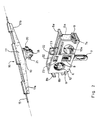
- Figure 1 is a part-sectional perspective view of a curtain support embodying this invention;
- Figure 2 is an exploded perspective view of a cart for the support in Figure 1; and
- Figures 3 to 5 show schematically in top plan view a plurality of carts and their operation when moved from a spread position to a gathered position, respectively.
- In the drawings, generally shown at 1 is a support for curtains embodying this invention.
- The
support 1 comprises atubular slideway 2 having a substantially rectangular cross-sectional shape withside walls 2a, 2b and abottom wall 2c which defines alongitudinal aperture 3 spanning the full length of the slideway. - Each
wall 2a,2b is formed, on theslideway 2 interior, with arespective rib bottom wall 2c. - A plurality of carts, all alike and shown at 5, fit slidably inside the
slideway 2. Eachcart 5 comprises an essentially flattenedparallelepipedic body 6 having a hook 7 mounted centrally to its lower portion which is intended to suspend a curtain panel or louver and extends through theaperture 3, said hook being rotatable to a limited extent about its vertical axis by means of aconventional worm mechanism 8. - Said
mechanism 8 is driven through a splined bar 9 running inside theslideway 2 and fitting slidably in a friction clutch to drive themechanism 8 worm, which is in turn received in ahole 10 in thebody 6. - Each
cart 5 also has, on its opposed minor side walls, respectively shown at 6a and 6b, two parallel projections defining agroove 11 therebetween for receiving acorresponding rib 4a,b whereby thecart 5 is held guided in theslideway 2. - From each
side wall 6a, 6b, there extend two opposed shoes respectively inddicated at 7a, 8a and 7b, 8b, of which the shoes denoted by 7a,b and those denoted by 8a,b project in turn from opposed portions of thebody 6 in order for thecarts 5 to be huddled together into a pack withoutcorresponding shoes 7a,b and 8a,b interfering with the shoes of the adjacent carts. These shoes, which effectively increase the cart dimension along the cart running direction without enlarging the cart space requirement, are effective to prevent the carts from cocking inside theslideway 2 and jam the support. - To move the
carts 5 along theslideway 2, atowing string 15 is provided along which asmany anchor members 16 are attached as are the carts to be towed, a return string (not shown) being passed through afurther hole 10a in thebody 6. Theanchor members 16 are distributed along the towing string at pitch distances which will depend on the pitch distance selected for the curtain louvers to be carried on the support, and snap fitted to their corresponding carts, at the cart upper portion, in a manner to be explained. - Said
anchor members 16 are plastics moldings as are thecarts 5, and each comprised of a rod-shaped portion 17 defining two opposedarms 17a,b having thestring 15 molded in at sections thereof shown as enlarged portions in Figure 2. It may be seen that the overall length of the rod-shaped portion, measured between the free ends of same, is substantially greater than the cross dimension of theslideway 2 and corresponding cross dimension of thecarts 5. Formed at a middle location relatively to the rod-shaped portion and at right angles thereto is apin 18 having acollar 19 and two pairs of opposed teeth (one tooth in each pair is shown in the figure) shown at 20 and 21 respectively. - Each anchor member is swivel connected to the
body 6 of a corresponding cart with thepin 18 coaxial with the hook 7, that is at a middle location on the body. Twoundercuts 22 defining a pivot seat for thepin 18 are provided for the purpose on facing surfaces of the opposed major walls of thebody 6. Formed beneath theundercuts 22 arerespective openings 23 into which acorresponding tooth 21 is snap fitted, such that theanchor member 16 will be held on thebody 6 of thecorresponding cart 5 with thecollar 19 abutting on the top free edge of the major walls of same. If required, the seat for thepin 18 may be offset on thebody 6 to take account of the eccentricity of the point of application of the frictional forces resulting from the sum of the friction resistances met by the cart in the slideway, on the one side, plus those imposed on the cart by the splined bar 9, on the other side. - The oscillation of the
anchor element 16 relatively to thebody 6 is limited to an angle of approximately 20-40° from a position of thearms 17a,b of substantial alignment with the direction of movement of thecarts 5 along theslideway 2. This limitation is controlled by theteeth 20 in the first pair interfering with the major walls of thebody 6, in one direction, and by theteeth 21 interfering with the contours of thecorresponding openings 23 in the opposite direction. - The operation of the inventive support will be now described making specific reference to Figures 3 to 5.
- In Figure 3, the
carts 5 are shown in their spread positions, such as may occur as the carts are towed out to stretch the louver associated therewith, for example. It may be noted that thearms 17a,b of the anchor members are aligned to thetowing string 15 and centered to their corresponding carts, such that there may be no components of the towing force tending to cock thecarts 5 in theslideway 2. In addition, with the louver stretched, the string will exert no springback action on the carts because it lies on a perfectly straight line. - In Figures 4 and 5, the carts are shown in a gathered position (the gap between adjacent carts has been exaggerated in Figure 4 for clarity). It may be noted that, on the carts being pulled toward one another, the
anchor member 16 is swung from its position aligned to the direction of movement of same (arrow F) to a position at an angle of about 20-30° from the previous one. This oscillation is limited by theteeth slideway 2. - As the carts are brought closer to one another, the
string 15 segments between adjacent anchor members are flexed into side-by-side bights which are held by thearms 17a,b above thecarriages 5 and by the bodies themselves of the adjacent carts. This expedient permits of the use of specially thin towing strings of circular cross-sectional shape, without this involving any risk of string bights sagging down between adjacent carts to block the carts in the slideway. - The use of thin strings affords the important advantage of removing any springback from the string apt to bias the carts to their spread positions.
- By using circular cross-section strings, moreover, the advantage is secured that a preferential (edge on) orientation of the string during the anchor member molding process is no longer required.
- It may be noted, in particular, that the breadth of the string bights can exceed by far the cross dimension of the carts (breadth of the slideway) as a result of the set imposed by the limited oscillation of the anchor members and the support from the
arms 17a,b. - A further advantage of this invention is that, with any components substantially cancel led of the cart towing force which may tend to cock the carts in the slideway and the shoes provided for added guide, the space requirements of the carts in their direction of movement are significantly reduced, which results in less space being occupied by the curtain in its gathered condition.
Claims (12)
- A support for curtains, particularly curtains of the adjustable sun-louver type, comprising a plurality of carts (5) fitting slidably in a slideway (2) and being interconnected, serially to one another or in clusters, by a string (15) for sequentially towing them along said slideway from a gathered position, where said carts are packed together, to a spread position where said carts are set at pitch distances from one another along said slideway, said string being attached to each cart by a corresponding anchor member (16) effective to bias said string to huddle into side-by-side bights above said carts when the latter are packed in said gathered position, characterized in that said anchor member comprises at least one support arm (17a, b) for said string jutting out from a corresponding cart and being adapted to hold said string some distance above the corresponding cart.
- A support according to Claim 1, characterized in that said at least one arm (17a, b) is, at least with the carts in their gathered position, so arranged relatively to its corresponding cart as to form an angle in the 1° to 89° range with an axis of said slideway coincident with the direction of movement of the carts.
- A support according to either Claim 1 or 2, characterized in that said anchor member comprised two opposed substantially aligned (17a, b) jutting out from opposed sides of the corresponding cart.
- A support according to one or more of the preceding claims, characterized in that said anchor member (16) is swivel mounted to a corresponding one of said carts (5).
- A support according to Claim 4, characterized in that said anchor element (16) is pivotable on its corresponding cart (5) between a substantially aligned position with said direction of movement of the carts along said slideway and an angled position to the former.
- A support according to Claim 5, characterized in that said cart and said anchor member are provided with means of limiting the pivotal movement (20-23) of said anchor member.
- A support according to one or more of the preceding claims, characterized in that the overall reach of said arms (17a, b) is substantially greater than the dimension of said carts (5) in the transverse direction to said direction of movement along said slideway (2).
- A support according to one or more of the preceding claims, characterized in that said anchor member is snap fitted to its corresponding cart.
- A support according to one or more of the preceding claims, characterized in that the anchor member is a plastics molding and attached to said string by molding the latter at least partway in said arms (17a, b).
- A support according to one or more of the preceding claims, characterized in that said anchor member (16) is mounted centrally on its corresponding cart (5).
- A support according to one or more of the preceding claims, characterized in that it comprises, on each cart, at least one pair of shoes (7a, b; 8a, b) extending laterally of the cart and parallel with the direction of movement of the same and co-operating with side walls of said slideway.
- A towing string for carts of curtain support, comprising a plurality of the anchor members according to Claim 9 distributed at pitch distances from one another.
Applications Claiming Priority (2)
| Application Number | Priority Date | Filing Date | Title |
|---|---|---|---|
| IT41560A IT1238846B (en) | 1990-03-14 | 1990-03-14 | CURTAIN SUPPORT, PARTICULARLY OF THE TYPE WITH ADJUSTABLE PANELS |
| IT4156090 | 1990-03-14 |
Publications (2)
| Publication Number | Publication Date |
|---|---|
| EP0446587A1 true EP0446587A1 (en) | 1991-09-18 |
| EP0446587B1 EP0446587B1 (en) | 1994-08-31 |
Family
ID=11251184
Family Applications (1)
| Application Number | Title | Priority Date | Filing Date |
|---|---|---|---|
| EP91101041A Expired - Lifetime EP0446587B1 (en) | 1990-03-14 | 1991-01-28 | A support for curtains, particularly curtains of the adjustable sun-louver type |
Country Status (9)
| Country | Link |
|---|---|
| US (1) | US5146970A (en) |
| EP (1) | EP0446587B1 (en) |
| JP (1) | JPH04227210A (en) |
| AT (1) | ATE110818T1 (en) |
| AU (1) | AU638534B2 (en) |
| CA (1) | CA2036572A1 (en) |
| DE (1) | DE69103651T2 (en) |
| IT (1) | IT1238846B (en) |
| PT (1) | PT8632T (en) |
Cited By (7)
| Publication number | Priority date | Publication date | Assignee | Title |
|---|---|---|---|---|
| EP0833034A2 (en) * | 1996-09-30 | 1998-04-01 | Hunter Douglas International Nv | A control system for a vertical vane covering for architectural openings |
| US6135188A (en) * | 1996-09-30 | 2000-10-24 | Hunter Douglas Inc. | Tassel for control system for a vertical vane covering for architectural openings |
| US6311756B1 (en) | 1996-09-30 | 2001-11-06 | Hunter Douglas Inc. | Mounting system for coverings for architectural openings |
| US6325132B1 (en) | 1997-05-19 | 2001-12-04 | Hunter Douglas Inc. | Pantograph and control system for a vertical vane covering for architectural openings |
| US6491085B1 (en) | 1995-06-07 | 2002-12-10 | Hunter Douglas Inc. | Control and suspension system for a vertical vane covering for architectural openings |
| US6755230B2 (en) | 2001-04-16 | 2004-06-29 | Hunter Douglas Inc. | Powered control system for a covering for architectural openings |
| GB2435665A (en) * | 2006-03-03 | 2007-09-05 | Ya Li Lin | Vertical shade and sliding member |
Families Citing this family (3)
| Publication number | Priority date | Publication date | Assignee | Title |
|---|---|---|---|---|
| US7552755B2 (en) * | 2006-11-28 | 2009-06-30 | Ya-Ying Lin | Movable seat of a vertical curtain |
| US20080163578A1 (en) * | 2007-01-08 | 2008-07-10 | Shin Jong Chang | Louver blades tapered in one direction |
| US20080202704A1 (en) * | 2007-02-27 | 2008-08-28 | Ya-Yin Lin | Vertical blind carrier |
Citations (3)
| Publication number | Priority date | Publication date | Assignee | Title |
|---|---|---|---|---|
| US2905237A (en) * | 1953-02-09 | 1959-09-22 | Robert C Clark | Vertically slatted blinds for windows |
| US3851699A (en) * | 1973-01-26 | 1974-12-03 | H Shapiro | Vertical louver type window drape |
| US4390055A (en) * | 1980-08-06 | 1983-06-28 | Saf-T-Trac Company | Drapery carrier |
Family Cites Families (3)
| Publication number | Priority date | Publication date | Assignee | Title |
|---|---|---|---|---|
| US4724883A (en) * | 1985-11-07 | 1988-02-16 | Leibowitz Martin Nick | Drapery and vertical blind system |
| GB2168090B (en) * | 1984-12-06 | 1988-02-24 | Hunter Douglas Ind Bv | Suspended ceiling |
| DE3525590A1 (en) * | 1985-07-18 | 1987-01-22 | Sunteca Sonnenschutz | Spacers for running carriages in vertical blinds |
-
1990
- 1990-03-14 IT IT41560A patent/IT1238846B/en active IP Right Grant
-
1991
- 1991-01-28 DE DE69103651T patent/DE69103651T2/en not_active Expired - Fee Related
- 1991-01-28 AT AT91101041T patent/ATE110818T1/en not_active IP Right Cessation
- 1991-01-28 EP EP91101041A patent/EP0446587B1/en not_active Expired - Lifetime
- 1991-01-31 AU AU70097/91A patent/AU638534B2/en not_active Ceased
- 1991-02-19 CA CA002036572A patent/CA2036572A1/en not_active Abandoned
- 1991-03-11 JP JP3069476A patent/JPH04227210A/en active Pending
- 1991-03-14 US US07/669,692 patent/US5146970A/en not_active Expired - Fee Related
-
1992
- 1992-11-09 PT PT8632U patent/PT8632T/en unknown
Patent Citations (3)
| Publication number | Priority date | Publication date | Assignee | Title |
|---|---|---|---|---|
| US2905237A (en) * | 1953-02-09 | 1959-09-22 | Robert C Clark | Vertically slatted blinds for windows |
| US3851699A (en) * | 1973-01-26 | 1974-12-03 | H Shapiro | Vertical louver type window drape |
| US4390055A (en) * | 1980-08-06 | 1983-06-28 | Saf-T-Trac Company | Drapery carrier |
Cited By (11)
| Publication number | Priority date | Publication date | Assignee | Title |
|---|---|---|---|---|
| US6491085B1 (en) | 1995-06-07 | 2002-12-10 | Hunter Douglas Inc. | Control and suspension system for a vertical vane covering for architectural openings |
| EP0833034A2 (en) * | 1996-09-30 | 1998-04-01 | Hunter Douglas International Nv | A control system for a vertical vane covering for architectural openings |
| EP0833034A3 (en) * | 1996-09-30 | 2000-02-09 | Hunter Douglas International Nv | A control system for a vertical vane covering for architectural openings |
| US6116322A (en) * | 1996-09-30 | 2000-09-12 | Hunter Douglas Inc. | Control system for a vertical vane covering for architectural openings |
| US6135188A (en) * | 1996-09-30 | 2000-10-24 | Hunter Douglas Inc. | Tassel for control system for a vertical vane covering for architectural openings |
| US6311756B1 (en) | 1996-09-30 | 2001-11-06 | Hunter Douglas Inc. | Mounting system for coverings for architectural openings |
| US6408924B1 (en) | 1996-09-30 | 2002-06-25 | Hunter Douglas Inc. | Control system for a vertical vane covering for architectural openings |
| US6457509B1 (en) | 1996-09-30 | 2002-10-01 | Hunter Douglas Inc. | Hanger pin for vertical vane coverings for architectural openings |
| US6325132B1 (en) | 1997-05-19 | 2001-12-04 | Hunter Douglas Inc. | Pantograph and control system for a vertical vane covering for architectural openings |
| US6755230B2 (en) | 2001-04-16 | 2004-06-29 | Hunter Douglas Inc. | Powered control system for a covering for architectural openings |
| GB2435665A (en) * | 2006-03-03 | 2007-09-05 | Ya Li Lin | Vertical shade and sliding member |
Also Published As
| Publication number | Publication date |
|---|---|
| AU638534B2 (en) | 1993-07-01 |
| EP0446587B1 (en) | 1994-08-31 |
| PT8632T (en) | 1993-06-30 |
| DE69103651T2 (en) | 1995-04-27 |
| JPH04227210A (en) | 1992-08-17 |
| US5146970A (en) | 1992-09-15 |
| DE69103651D1 (en) | 1994-10-06 |
| CA2036572A1 (en) | 1991-09-15 |
| IT9041560A1 (en) | 1991-09-14 |
| IT9041560A0 (en) | 1990-03-14 |
| ATE110818T1 (en) | 1994-09-15 |
| AU7009791A (en) | 1991-09-19 |
| IT1238846B (en) | 1993-09-03 |
Similar Documents
| Publication | Publication Date | Title |
|---|---|---|
| US5146970A (en) | Support for curtains, particularly curtains of the adjustable sun-louver type | |
| US6216849B1 (en) | Belt assembly | |
| EP0473211A1 (en) | Section bar for supporting curtains, allowing said curtains to slide, and variable-position juncture element | |
| US5504977A (en) | Device for releasably holding cords | |
| US4838409A (en) | Scraper device for conveyor belts | |
| ATE263347T1 (en) | REFRIGERATOR OR FREEZER HAVING A DOOR HAVING A HANDLE | |
| US3916477A (en) | Drapery supporting bracket | |
| RU2001108846A (en) | PLASTIC IMPLANT | |
| JP2007537113A (en) | Conveyor mat module and assembly conveyor mat | |
| JPH0631500B2 (en) | Belt-shaped cart | |
| JPH05278828A (en) | Bend segment for chain conveyer | |
| DE20111049U1 (en) | Zipper pull for an invisible zipper | |
| US4116257A (en) | Strip curtain | |
| AU597863B2 (en) | Support for an operating element of a venetian blind assembly | |
| US5887636A (en) | Venetian blind | |
| US4519433A (en) | Drive sprocket for traverse rod | |
| EP0444743B1 (en) | Bracket and section intended for fixing a horizontal shade in a greenhouse or glasshouse | |
| US4061369A (en) | Catches | |
| EP0994282A2 (en) | Rack sections for joining together, which can be hooked onto a support bar, both straight and curved | |
| US5970696A (en) | Rake adjustable between a right-handed and a left-handed position | |
| US5878466A (en) | Buckle | |
| NL1032241C2 (en) | Clamping member. | |
| DE20119684U1 (en) | Swivel mechanism for a sofa | |
| JPH0620416B2 (en) | Curtain hanging device | |
| US4010850A (en) | Device for suspending objects |
Legal Events
| Date | Code | Title | Description |
|---|---|---|---|
| PUAI | Public reference made under article 153(3) epc to a published international application that has entered the european phase |
Free format text: ORIGINAL CODE: 0009012 |
|
| AK | Designated contracting states |
Kind code of ref document: A1 Designated state(s): AT BE CH DE DK ES FR GB GR LI LU NL SE |
|
| 17P | Request for examination filed |
Effective date: 19911017 |
|
| 17Q | First examination report despatched |
Effective date: 19921001 |
|
| GRAA | (expected) grant |
Free format text: ORIGINAL CODE: 0009210 |
|
| AK | Designated contracting states |
Kind code of ref document: B1 Designated state(s): AT BE CH DE DK ES FR GB GR LI LU NL SE |
|
| PG25 | Lapsed in a contracting state [announced via postgrant information from national office to epo] |
Ref country code: NL Effective date: 19940831 Ref country code: LI Effective date: 19940831 Ref country code: GR Free format text: LAPSE BECAUSE OF FAILURE TO SUBMIT A TRANSLATION OF THE DESCRIPTION OR TO PAY THE FEE WITHIN THE PRESCRIBED TIME-LIMIT Effective date: 19940831 Ref country code: FR Effective date: 19940831 Ref country code: ES Free format text: THE PATENT HAS BEEN ANNULLED BY A DECISION OF A NATIONAL AUTHORITY Effective date: 19940831 Ref country code: DK Effective date: 19940831 Ref country code: CH Effective date: 19940831 Ref country code: BE Effective date: 19940831 Ref country code: AT Effective date: 19940831 |
|
| REF | Corresponds to: |
Ref document number: 110818 Country of ref document: AT Date of ref document: 19940915 Kind code of ref document: T |
|
| REF | Corresponds to: |
Ref document number: 69103651 Country of ref document: DE Date of ref document: 19941006 |
|
| PG25 | Lapsed in a contracting state [announced via postgrant information from national office to epo] |
Ref country code: SE Effective date: 19941130 |
|
| REG | Reference to a national code |
Ref country code: CH Ref legal event code: PL |
|
| PGFP | Annual fee paid to national office [announced via postgrant information from national office to epo] |
Ref country code: GB Payment date: 19941216 Year of fee payment: 5 |
|
| EN | Fr: translation not filed | ||
| PG25 | Lapsed in a contracting state [announced via postgrant information from national office to epo] |
Ref country code: LU Free format text: LAPSE BECAUSE OF NON-PAYMENT OF DUE FEES Effective date: 19950131 |
|
| NLV1 | Nl: lapsed or annulled due to failure to fulfill the requirements of art. 29p and 29m of the patents act | ||
| PLBE | No opposition filed within time limit |
Free format text: ORIGINAL CODE: 0009261 |
|
| STAA | Information on the status of an ep patent application or granted ep patent |
Free format text: STATUS: NO OPPOSITION FILED WITHIN TIME LIMIT |
|
| 26N | No opposition filed | ||
| PG25 | Lapsed in a contracting state [announced via postgrant information from national office to epo] |
Ref country code: DE Effective date: 19951003 |
|
| PG25 | Lapsed in a contracting state [announced via postgrant information from national office to epo] |
Ref country code: GB Effective date: 19960128 |
|
| GBPC | Gb: european patent ceased through non-payment of renewal fee |
Effective date: 19960128 |