EP0445728B1 - Apparatus and method for cleaning solid surface - Google Patents
Apparatus and method for cleaning solid surface Download PDFInfo
- Publication number
- EP0445728B1 EP0445728B1 EP91103304A EP91103304A EP0445728B1 EP 0445728 B1 EP0445728 B1 EP 0445728B1 EP 91103304 A EP91103304 A EP 91103304A EP 91103304 A EP91103304 A EP 91103304A EP 0445728 B1 EP0445728 B1 EP 0445728B1
- Authority
- EP
- European Patent Office
- Prior art keywords
- cleaning
- cleaning liquid
- solid surface
- liquid
- eddy
- Prior art date
- Legal status (The legal status is an assumption and is not a legal conclusion. Google has not performed a legal analysis and makes no representation as to the accuracy of the status listed.)
- Expired - Lifetime
Links
Images

Classifications
-
- H—ELECTRICITY
- H05—ELECTRIC TECHNIQUES NOT OTHERWISE PROVIDED FOR
- H05K—PRINTED CIRCUITS; CASINGS OR CONSTRUCTIONAL DETAILS OF ELECTRIC APPARATUS; MANUFACTURE OF ASSEMBLAGES OF ELECTRICAL COMPONENTS
- H05K3/00—Apparatus or processes for manufacturing printed circuits
- H05K3/22—Secondary treatment of printed circuits
- H05K3/26—Cleaning or polishing of the conductive pattern
-
- B—PERFORMING OPERATIONS; TRANSPORTING
- B08—CLEANING
- B08B—CLEANING IN GENERAL; PREVENTION OF FOULING IN GENERAL
- B08B3/00—Cleaning by methods involving the use or presence of liquid or steam
- B08B3/04—Cleaning involving contact with liquid
- B08B3/06—Cleaning involving contact with liquid using perforated drums in which the article or material is placed
-
- B—PERFORMING OPERATIONS; TRANSPORTING
- B08—CLEANING
- B08B—CLEANING IN GENERAL; PREVENTION OF FOULING IN GENERAL
- B08B7/00—Cleaning by methods not provided for in a single other subclass or a single group in this subclass
- B08B7/02—Cleaning by methods not provided for in a single other subclass or a single group in this subclass by distortion, beating, or vibration of the surface to be cleaned
-
- B—PERFORMING OPERATIONS; TRANSPORTING
- B24—GRINDING; POLISHING
- B24B—MACHINES, DEVICES, OR PROCESSES FOR GRINDING OR POLISHING; DRESSING OR CONDITIONING OF ABRADING SURFACES; FEEDING OF GRINDING, POLISHING, OR LAPPING AGENTS
- B24B31/00—Machines or devices designed for polishing or abrading surfaces on work by means of tumbling apparatus or other apparatus in which the work and/or the abrasive material is loose; Accessories therefor
- B24B31/003—Machines or devices designed for polishing or abrading surfaces on work by means of tumbling apparatus or other apparatus in which the work and/or the abrasive material is loose; Accessories therefor whereby the workpieces are mounted on a holder and are immersed in the abrasive material
-
- H—ELECTRICITY
- H05—ELECTRIC TECHNIQUES NOT OTHERWISE PROVIDED FOR
- H05K—PRINTED CIRCUITS; CASINGS OR CONSTRUCTIONAL DETAILS OF ELECTRIC APPARATUS; MANUFACTURE OF ASSEMBLAGES OF ELECTRICAL COMPONENTS
- H05K2201/00—Indexing scheme relating to printed circuits covered by H05K1/00
- H05K2201/02—Fillers; Particles; Fibers; Reinforcement materials
- H05K2201/0203—Fillers and particles
- H05K2201/0206—Materials
- H05K2201/0209—Inorganic, non-metallic particles
-
- H—ELECTRICITY
- H05—ELECTRIC TECHNIQUES NOT OTHERWISE PROVIDED FOR
- H05K—PRINTED CIRCUITS; CASINGS OR CONSTRUCTIONAL DETAILS OF ELECTRIC APPARATUS; MANUFACTURE OF ASSEMBLAGES OF ELECTRICAL COMPONENTS
- H05K2203/00—Indexing scheme relating to apparatus or processes for manufacturing printed circuits covered by H05K3/00
- H05K2203/02—Details related to mechanical or acoustic processing, e.g. drilling, punching, cutting, using ultrasound
- H05K2203/025—Abrading, e.g. grinding or sand blasting
-
- H—ELECTRICITY
- H05—ELECTRIC TECHNIQUES NOT OTHERWISE PROVIDED FOR
- H05K—PRINTED CIRCUITS; CASINGS OR CONSTRUCTIONAL DETAILS OF ELECTRIC APPARATUS; MANUFACTURE OF ASSEMBLAGES OF ELECTRICAL COMPONENTS
- H05K2203/00—Indexing scheme relating to apparatus or processes for manufacturing printed circuits covered by H05K3/00
- H05K2203/07—Treatments involving liquids, e.g. plating, rinsing
- H05K2203/0736—Methods for applying liquids, e.g. spraying
- H05K2203/0743—Mechanical agitation of fluid, e.g. during cleaning of the conductive pattern
-
- H—ELECTRICITY
- H05—ELECTRIC TECHNIQUES NOT OTHERWISE PROVIDED FOR
- H05K—PRINTED CIRCUITS; CASINGS OR CONSTRUCTIONAL DETAILS OF ELECTRIC APPARATUS; MANUFACTURE OF ASSEMBLAGES OF ELECTRICAL COMPONENTS
- H05K2203/00—Indexing scheme relating to apparatus or processes for manufacturing printed circuits covered by H05K3/00
- H05K2203/07—Treatments involving liquids, e.g. plating, rinsing
- H05K2203/0779—Treatments involving liquids, e.g. plating, rinsing characterised by the specific liquids involved
- H05K2203/0783—Using solvent, e.g. for cleaning; Regulating solvent content of pastes or coatings for adjusting the viscosity
-
- H—ELECTRICITY
- H05—ELECTRIC TECHNIQUES NOT OTHERWISE PROVIDED FOR
- H05K—PRINTED CIRCUITS; CASINGS OR CONSTRUCTIONAL DETAILS OF ELECTRIC APPARATUS; MANUFACTURE OF ASSEMBLAGES OF ELECTRICAL COMPONENTS
- H05K2203/00—Indexing scheme relating to apparatus or processes for manufacturing printed circuits covered by H05K3/00
- H05K2203/07—Treatments involving liquids, e.g. plating, rinsing
- H05K2203/0779—Treatments involving liquids, e.g. plating, rinsing characterised by the specific liquids involved
- H05K2203/0786—Using an aqueous solution, e.g. for cleaning or during drilling of holes
Definitions
- the present invention relates to an apparatus and method for cleaning a solid surface, and particularly to an apparatus and method for cleaning a part such as a metal workpiece, a print circuit board or the like, which has a surface having a complicated shape.
- chlorine-type organic solvents such as trichloroethylene and the like and 1,1,2-trichloro-1,2,2-trifluoroethane (CFC-113 in abbreviation) are generally used for cleaning out the oils, greases and waxes adhering to metal workpieces, print circuit boards and the like.
- the former method using fine particles is effective to clean a flat board such as a glass board, a Si wafer or the like.
- this method cannot uniformly clean the whole surface of a print circuit board on which many electronic parts are mounted, a part having a convex and concave surface or a complicated structure with holes because the motion of the dry ice used for cleaning in a constant direction causes a shadow portion on which the fine particles cannot be sprayed.
- the German Patent DE-C-880 630 which forms the basis for the pre-characterising part of claims 1 and 5, discloses a device for removing a discloses a device for removing a substance of a decade tooth portion from a tooth.
- the normal portion of the tooth is covered with a rubber cap having an opening at a position corresponding to the decade tooth portion.
- a sleeve of a middle ring is secured to the decade tooth through dental cement, the interior of the middle ring being filled with a liquid containing a disinfectant and abrasive particles and then being kept by a rubber plug.
- a shaft having a propeller is inserted in the middle ring through a small opening provided on the rubber plug. A deflow is caused to occur by rotating the shaft.
- the abrasive particles are colliding with the decade tooth portion to bear by remove the substance of the decade tooth portion.
- the device of the German Patent does not consider that a substance removed into liquids by the abrasive particles sticks again onto the surface to be cleaned.
- a substance removed into liquids by the abrasive particles sticks again onto the surface to be cleaned.
- dirt such as solid fat or oil
- German Patent discloses the feature of AD-flow, but does not mention anything about the kind of substances to be used and the specific heating to be applied.
- the first object of the present invention is achieved by an apparatus according to claim 1.
- the means for bringing the cleaning liquid into an eddy-flow state may be a stirring apparatus.
- the means for bringing the cleaning liquid into an eddy-flow state may be a vibration generating apparatus.
- the apparatus may further comprise means for mixing air bubbles in the cleaning liquid.
- the second object of the present invention is achieved by a method according to claim 5.
- the state of the cleaning liquid obtained by mixing the insoluble particles in the liquid may be changed to an eddy-flow state by mixing air bubble in the cleaning liquid.
- the state of the cleaning liquid obtained by mixing the insoluble particles in the liquid may be changed to an eddy-flow state by vibrating the closed cleaning bath containing a vapor phase and the cleaning liquid.
- the first object of the present invention can be achieved by an apparatus according to claim 1.
- the second object of the present invention can be achieved by a method according to claim 5.
- a substance to be cleaned off is liquid or solid fat or oil
- calcium carbonate particles having the property of adsorbing such liquid or solid fat or oil are used.
- the cleaning liquid contains the insoluble particles dispersed therein so that the insoluble particles are caused to collide with a board surface by virtue of the kinetic energy, thereby cleaning the surface.
- a predetermined number of collisions of the insoluble particles in the cleaning liquid causes cleaning of the surface.
- the use of a small amount of insoluble particles requires much time for cleaning, while the use of a large amount of insoluble particles requires only a little time for cleaning.
- the composition of the cleaning fluid has no relation to the cleaning capability.
- a stirring apparatus, a vibration generating apparatus or the like is used as the means for providing an eddy flow in the cleaning liquid.
- the means for mixing bubbles in the cleaning liquid may be used in combination with the above means forming an eddy flow.
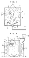
- Fig. 1 is a schematic drawing of an apparatus for cleaning a solid surface of the present invention.
- reference numeral 1 denotes a cleaning liquid
- reference numeral 2, a cleaning bath reference numeral 3, a part to be cleaned
- reference numeral 4, a cage in which the part 3 is placed reference numeral 5, a stirring apparatus
- reference numeral 6, fine particles reference numeral 7, a contaminant, reference numeral 8, a hole of the part 3 to be cleaned
- reference numeral 10 a bubble generator.
- the part 3 to be cleaned having a surface provided with a complicated shape was placed in the exclusive jig 4 which has a mesh structure or the like so as to prevent the cage 4 from interrupting the flow of the cleaning liquid 1, and the part 3 was immersed in the cleaning liquid 1 containing the fine particles 6 in the cleaning bath 2.
- the cleaning bath was equipped with the stirring apparatus 5 such as a rolling fan for causing the cleaning liquid 1 to flow which can accurately cause a liquid current by rotation.
- the fine particles 6 contained in the cleaning liquid 1 were moved together with the liquid current, caused to collide with the surface of the part 3 by virtue of inertia so as to separate the contaminant 7 adhering to the surface of the part 3 and entrap the contaminant 7 in the cleaning liquid 1, thereby removing the contaminant 7.
- the stirring apparatus 5 was provided with the function of controlling the rotational speed, rotational direction and the angle with respect to the part 3 for converting the liquid flow into an eddy flow so as to cause a flow in the hole 8.
- the contaminant 7 in the hole 8 of the part 3 to be cleaned having a complicated structure was thus able to be removed by causing the particles 6 to collide with the entire internal surface of the hole 8, whereby the overall surface of the part 3 was cleaned.
- the cleaning apparatus may be provided with a gas supply 9 for supplying bubbles in the cleaning liquid 1 and a bubble generator 10 for generating fine bubbles of gas by employing ultrasonic waves, both of which are provided together with the stirring apparatus 5 or in place of the apparatus 5 so that the cleaning efficiency in the hole 8 can be further increased.
- the above cleaning method mainly utilizes the liquid dynamic effect of the cleaning liquid.
- the efficiency of removal of the rosin wax fused on a glass board was increased by several times when the temperature of the cleaning liquid is increased to 60 to 80°C.
- the type of the particles, which is effective for cleaning, was particles of calcium carbonate, which were insoluble in the cleaning liquid.
- a particle size of several »m to several mm was effective.
- the specific gravity of the particles may be a value which allows the particles to suspend in a liquid state (stirring function) (which may allows the particles to sediment in the liquid in a stationary state).
- the hardness of the particles had a relation to the material of the part to be cleaned and the flow rate of the liquid, it was necessary to select a degree of hardness which caused no flaw on a surface.
- Pure water was used as the cleaning liquid because of its easy handling, safety and low cost.
- Fig. 2 is a schematic drawing of a cleaning apparatus which is particularly effective to a substance to be cleaned off such as solid fat or oil.
- reference numeral 1 denotes a cleaning liquid
- reference numeral 2, a cleaning bath reference numeral 3, a part to be cleaned
- reference numeral 5, a stirring apparatus
- reference numeral 6, fine particles reference numeral 8 a hole of the part 3 to be cleaned
- reference numeral 11 a heating heater
- reference numeral 12 a temperature measuring device
- reference numeral 13 a temperature controller
- reference numeral 14 a solid fat or oil contaminant.
- the part 3 to be cleaned having a surface having a complicated shape was placed in the exclusive jig 4 which has a mesh structure or the like so as to prevent the jig 4 from interrupting the flow of the cleaning liquid 1, the part 3 being immersed in the cleaning liquid 1 containing the fine particles 6 in the cleaning bath 2.
- the cleaning bath was equipped with the stirring apparatus 5 such as a rolling fan which accurately caused a liquid current by rotation for causing the cleaning liquid 1 to flow.
- the cleaning liquid 1 was heated to a desired temperature by the heating heater 11, the temperature of the cleaning liquid 1 being measured by the temperature measuring device 12.
- the heating heater 11 was turned on and off by the temperature controller 13 which received the measurement results from the temperature measuring device 12.
- the solid fat or oil contaminant 14 adhering to the part 3 to be cleaned was heated and softened by the cleaning liquid 1 heated by the heating heater 11.
- the fine calcium carbonate particles 6 contained in the cleaning liquid 1 were moved together with the flow of the cleaning liquid 1 and caused to collide with a surface of the parts 3 by virtue of inertia so as to separate the softened solid fat or oil contaminant 14 adhering to the surface and entraped the contaminant 14 in the cleaning liquid 1, thereby removing the contaminant 14.
- the stirring apparatus 5 was provided with the function of controlling the rotational speed, rotational direction and the angle with respect to the part 3 for converting the liquid flow into an eddy flow so as to cause a flow in the hole 8.
- the contaminant 7 in the hole 8 of the part 3 to be cleaned having a complicated structure was thus able to be removed by causing the particles 6 to collide with the entire internal surface of the hole 8, whereby the overall surface of the part 3 can be cleaned.
- Fig. 3 shows a relation between the temperature of the cleaning liquid and the cleaning time when solid fat or oil contaminant was cleaned off by the cleaning apparatus in accordance with the present invention.
- Table 1 shows the time required for removing each of the five types of wax including the stick wax, sky wax, hot wax, apiezon wax and hot melt, which were used as solid fat or oil, by cleaning using a cleaning liquid at two temperatures, a temperature below the softening point of the wax and a temperature above the softening point of the wax.
- mark x represents the cleaning result that the fat or oil could not be removed by cleaning for 20 minutes. It can be seen from Table 1 that any one of the wax types used can be removed by cleaning using the cleaning liquid at a temperature near the softening point of the wax for a time of about 1 minute. It can also be seen that much time is required for cleaning by using the cleaning liquid at a temperature below the softening point.
- the present invention therefore enables the contaminant adhering to a surface of a substrate to be cleaned, which surface has a complicated shape and a structure with a hole, a recess or the like, to be easily and efficiently removed by cleaning.
- the present invention also enables the contaminant adhering to a surface of a substance to be cleaned having a complicated shape and a structure with a hole, a recess or the like to be easily and efficiently removed by cleaning for a short time.
- the present invention has the significant effect of cleaning off solid fats and oils without using CFC or a chlorocarbon-type organic solvent which has at present an environmental problem all over the world.
Description
- The present invention relates to an apparatus and method for cleaning a solid surface, and particularly to an apparatus and method for cleaning a part such as a metal workpiece, a print circuit board or the like, which has a surface having a complicated shape.
- In prior arts, there are disclosed cleaning apparatus and method using dry ice particles as disclosed in Japanese Patent Laid-Open No. 63-266836, and the ice fine particle generating apparatus using ice fine particles is disclosed in Japanese Patent Laid-Open No. 63-283133. In these methods and apparatuses, fine particles of dry ice or ice are blown out of a nozzle and sprayed on a substance to be cleaned for removing contaminants from the surfaces of the substance.
- In addition, in other prior arts, chlorine-type organic solvents such as trichloroethylene and the like and 1,1,2-trichloro-1,2,2-trifluoroethane (CFC-113 in abbreviation) are generally used for cleaning out the oils, greases and waxes adhering to metal workpieces, print circuit boards and the like.
- In the above-described prior arts, the former method using fine particles is effective to clean a flat board such as a glass board, a Si wafer or the like. However, this method cannot uniformly clean the whole surface of a print circuit board on which many electronic parts are mounted, a part having a convex and concave surface or a complicated structure with holes because the motion of the dry ice used for cleaning in a constant direction causes a shadow portion on which the fine particles cannot be sprayed.
- In the prior arts, the latter method using a chlorine-type organic solvent such as trichloroethylene or the like has a danger of contaminating underground water, and, since CFC-113 depletes the stratospheric ozone, the use thereof is severely restricted.
- The German Patent DE-C-880 630, which forms the basis for the pre-characterising part of
claims 1 and 5, discloses a device for removing a discloses a device for removing a substance of a decade tooth portion from a tooth. In the device the normal portion of the tooth is covered with a rubber cap having an opening at a position corresponding to the decade tooth portion. A sleeve of a middle ring is secured to the decade tooth through dental cement, the interior of the middle ring being filled with a liquid containing a disinfectant and abrasive particles and then being kept by a rubber plug. A shaft having a propeller is inserted in the middle ring through a small opening provided on the rubber plug. A deflow is caused to occur by rotating the shaft. The abrasive particles are colliding with the decade tooth portion to bear by remove the substance of the decade tooth portion. - The device of the German Patent does not consider that a substance removed into liquids by the abrasive particles sticks again onto the surface to be cleaned. In the case of cleaning dirt such as solid fat or oil, it is impossible to prevent the solid fat or oil from sticking again on the surface to be cleaned since the solid fat or oil is hardly scattered in a liquid.
- The German Patent discloses the feature of AD-flow, but does not mention anything about the kind of substances to be used and the specific heating to be applied.
- The first object of the present invention is achieved by an apparatus according to claim 1.
- The means for bringing the cleaning liquid into an eddy-flow state may be a stirring apparatus. Alternatively, the means for bringing the cleaning liquid into an eddy-flow state may be a vibration generating apparatus.
- In a preferred form of the apparatus for cleaning a solid surface, the apparatus may further comprise means for mixing air bubbles in the cleaning liquid.
- The second object of the present invention is achieved by a method according to
claim 5. - Preferably, the state of the cleaning liquid obtained by mixing the insoluble particles in the liquid may be changed to an eddy-flow state by mixing air bubble in the cleaning liquid. Alternatively, the state of the cleaning liquid obtained by mixing the insoluble particles in the liquid may be changed to an eddy-flow state by vibrating the closed cleaning bath containing a vapor phase and the cleaning liquid.
-
- Fig. 1 is a schematic drawing of an apparatus of cleaning a solid surface in accordance with the present invention;
- Fig. 2 is a schematic drawing of an apparatus of the present invention for cleaning a solid surface which apparatus is effective for solid fats and oils to be cleaned off; and
- Fig. 3 is a drawing showing a relation between the cleaning temperature and the cleaning time when solid fat or oil is cleaned off by using an apparatus of the invention for cleaning a solid surface.
- As a result of various experiments conducted by the inventors on an apparatus and method for cleaning a solid surface, the inventors obtained the following finding:
- The first object of the present invention can be achieved by an apparatus according to claim 1.
- The second object of the present invention can be achieved by a method according to
claim 5. - When a substance to be cleaned off is liquid or solid fat or oil, calcium carbonate particles having the property of adsorbing such liquid or solid fat or oil are used. The cleaning liquid contains the insoluble particles dispersed therein so that the insoluble particles are caused to collide with a board surface by virtue of the kinetic energy, thereby cleaning the surface. A predetermined number of collisions of the insoluble particles in the cleaning liquid causes cleaning of the surface. The use of a small amount of insoluble particles requires much time for cleaning, while the use of a large amount of insoluble particles requires only a little time for cleaning. Thus, the composition of the cleaning fluid has no relation to the cleaning capability. A stirring apparatus, a vibration generating apparatus or the like is used as the means for providing an eddy flow in the cleaning liquid. In order to improve the effect of the means for forming an eddy flow in the cleaning liquid, the means for mixing bubbles in the cleaning liquid may be used in combination with the above means forming an eddy flow.
- The present invention is described below with reference to embodiments.
- Fig. 1 is a schematic drawing of an apparatus for cleaning a solid surface of the present invention. In the drawing, reference numeral 1 denotes a cleaning liquid;
reference numeral 2, a cleaning bath;reference numeral 3, a part to be cleaned;reference numeral 4, a cage in which thepart 3 is placed;reference numeral 5, a stirring apparatus;reference numeral 6, fine particles;reference numeral 7, a contaminant,reference numeral 8, a hole of thepart 3 to be cleaned; reference numeral 9, a gas supply; andreference numeral 10, a bubble generator. - The operation of the apparatus is described below.
- The
part 3 to be cleaned having a surface provided with a complicated shape was placed in theexclusive jig 4 which has a mesh structure or the like so as to prevent thecage 4 from interrupting the flow of the cleaning liquid 1, and thepart 3 was immersed in the cleaning liquid 1 containing thefine particles 6 in thecleaning bath 2. The cleaning bath was equipped with the stirringapparatus 5 such as a rolling fan for causing the cleaning liquid 1 to flow which can accurately cause a liquid current by rotation. Thefine particles 6 contained in the cleaning liquid 1 were moved together with the liquid current, caused to collide with the surface of thepart 3 by virtue of inertia so as to separate the contaminant 7 adhering to the surface of thepart 3 and entrap the contaminant 7 in the cleaning liquid 1, thereby removing the contaminant 7. The stirringapparatus 5 was provided with the function of controlling the rotational speed, rotational direction and the angle with respect to thepart 3 for converting the liquid flow into an eddy flow so as to cause a flow in thehole 8. The contaminant 7 in thehole 8 of thepart 3 to be cleaned having a complicated structure was thus able to be removed by causing theparticles 6 to collide with the entire internal surface of thehole 8, whereby the overall surface of thepart 3 was cleaned. The cleaning apparatus may be provided with a gas supply 9 for supplying bubbles in the cleaning liquid 1 and abubble generator 10 for generating fine bubbles of gas by employing ultrasonic waves, both of which are provided together with thestirring apparatus 5 or in place of theapparatus 5 so that the cleaning efficiency in thehole 8 can be further increased. - The above cleaning method mainly utilizes the liquid dynamic effect of the cleaning liquid.
- Other considerable effects include the temperature effect of the cleaning liquid and the effect of characteristics of the fine particles in the cleaning liquid.
- In regard to the temperature effect, for example, the efficiency of removal of the rosin wax fused on a glass board was increased by several times when the temperature of the cleaning liquid is increased to 60 to 80°C.
- The type of the fine particles mixed in the cleaning liquid and the results of measurement of the mixing state, particle size, specific gravity, hardness and so on of the particles are described below.
- The type of the particles, which is effective for cleaning, was particles of calcium carbonate, which were insoluble in the cleaning liquid.
- A particle size of several »m to several mm was effective. The specific gravity of the particles may be a value which allows the particles to suspend in a liquid state (stirring function) (which may allows the particles to sediment in the liquid in a stationary state). Although the hardness of the particles had a relation to the material of the part to be cleaned and the flow rate of the liquid, it was necessary to select a degree of hardness which caused no flaw on a surface.
- Although the influences of the factors on an increase in the cleaning efficiency are related to each other and complicated, it was effective to use calcium carbonate particles when a precision part such as a print circuit board was cleaned by using as a cleaning liquid pure water.
- Pure water was used as the cleaning liquid because of its easy handling, safety and low cost.
- Fig. 2 is a schematic drawing of a cleaning apparatus which is particularly effective to a substance to be cleaned off such as solid fat or oil. In Fig. 2, reference numeral 1 denotes a cleaning liquid;
reference numeral 2, a cleaning bath;reference numeral 3, a part to be cleaned;reference numeral 4, a jig in which thepart 3 is placed;reference numeral 5, a stirring apparatus;reference numeral 6, fine particles;reference numeral 8, a hole of thepart 3 to be cleaned; reference numeral 11, a heating heater;reference numeral 12, a temperature measuring device; reference numeral 13, a temperature controller; and reference numeral 14, a solid fat or oil contaminant. - The operation of the apparatus is described below.
- The
part 3 to be cleaned having a surface having a complicated shape was placed in theexclusive jig 4 which has a mesh structure or the like so as to prevent thejig 4 from interrupting the flow of the cleaning liquid 1, thepart 3 being immersed in the cleaning liquid 1 containing thefine particles 6 in thecleaning bath 2. The cleaning bath was equipped with thestirring apparatus 5 such as a rolling fan which accurately caused a liquid current by rotation for causing the cleaning liquid 1 to flow. At the same time, the cleaning liquid 1 was heated to a desired temperature by the heating heater 11, the temperature of the cleaning liquid 1 being measured by thetemperature measuring device 12. The heating heater 11 was turned on and off by the temperature controller 13 which received the measurement results from thetemperature measuring device 12. The solid fat or oil contaminant 14 adhering to thepart 3 to be cleaned was heated and softened by the cleaning liquid 1 heated by the heating heater 11. The finecalcium carbonate particles 6 contained in the cleaning liquid 1 were moved together with the flow of the cleaning liquid 1 and caused to collide with a surface of theparts 3 by virtue of inertia so as to separate the softened solid fat or oil contaminant 14 adhering to the surface and entraped the contaminant 14 in the cleaning liquid 1, thereby removing the contaminant 14. The stirringapparatus 5 was provided with the function of controlling the rotational speed, rotational direction and the angle with respect to thepart 3 for converting the liquid flow into an eddy flow so as to cause a flow in thehole 8. Thecontaminant 7 in thehole 8 of thepart 3 to be cleaned having a complicated structure was thus able to be removed by causing theparticles 6 to collide with the entire internal surface of thehole 8, whereby the overall surface of thepart 3 can be cleaned. - Fig. 3 shows a relation between the temperature of the cleaning liquid and the cleaning time when solid fat or oil contaminant was cleaned off by the cleaning apparatus in accordance with the present invention.
- Table 1 shows the time required for removing each of the five types of wax including the stick wax, sky wax, hot wax, apiezon wax and hot melt, which were used as solid fat or oil, by cleaning using a cleaning liquid at two temperatures, a temperature below the softening point of the wax and a temperature above the softening point of the wax. In Table 1, mark x represents the cleaning result that the fat or oil could not be removed by cleaning for 20 minutes. It can be seen from Table 1 that any one of the wax types used can be removed by cleaning using the cleaning liquid at a temperature near the softening point of the wax for a time of about 1 minute. It can also be seen that much time is required for cleaning by using the cleaning liquid at a temperature below the softening point.
- The present invention therefore enables the contaminant adhering to a surface of a substrate to be cleaned, which surface has a complicated shape and a structure with a hole, a recess or the like, to be easily and efficiently removed by cleaning.
- The present invention also enables the contaminant adhering to a surface of a substance to be cleaned having a complicated shape and a structure with a hole, a recess or the like to be easily and efficiently removed by cleaning for a short time. Particularly, the present invention has the significant effect of cleaning off solid fats and oils without using CFC or a chlorocarbon-type organic solvent which has at present an environmental problem all over the world.

Claims (7)
- Apparatus for cleaning a solid surface (3) containing a solid fat or oil (7) thereon, comprising a cleaning bath (2) containing a cleaning liquid (1) and means (5) for bringing said cleaning liquid into an eddy-flow state,
characterized by
said cleaning liquid (1) being a mixture of pure water and calcium carbonate particles (6), and by means (11) for heating the cleaning liquid (1) up to a temperature near to softening point of said solid fat or oil (7 or 4). - Apparatus for cleaning a solid surface (3) according to claim 1, wherein said means (5) for bringing said cleaning liquid into an eddy-flow state is a stirring device (5).
- Apparatus for cleaning a solid surface (3) according to claim 1, wherein said means (5) for bringing said cleaning liquid into an eddy-flow state is a vibration generating device (5).
- Apparatus for cleaning a solid surface (3) according to claim 1, further comprising means (10) for mixing bubbles in said cleaning liquid (1).
- Method of cleaning a solid surface (3) by bringing a cleaning liquid (1) into contact with said solid surface (3) to be cleaned in a cleaning bath (2), which solid surface (3) includes a solid fat or oil (7) thereon, comprising the following steps:
mixing pure water and calcium carbonate particles (6) insoluble in water to thereby prepare said cleaning liquid (1), heating the cleaning liquid up to a temperature near to the softening point of said solid fat or oil (7), and making the cleaning liquid (1) to be in an eddy-flow state, whereby the softened solid fat or oil (14) is removed. - Method of cleaning a solid surface (3) according to claim 5, further comprising the step of mixing bubbles (10) in said cleaning liquid (1) so that the pure water and the calcium carbonate particles (6) insoluble in water are mixed in an eddy-flow state.
- Method of cleaning a solid surface (3) according to claim 5, further comprising the steps of closing the cleaning bath (2) and vibrating the cleaning bath (2) so that the mixture (1) of pure water and calcium carbonate particles (6) is in an eddy-flow state.
Applications Claiming Priority (2)
| Application Number | Priority Date | Filing Date | Title |
|---|---|---|---|
| JP53573/90 | 1990-03-07 | ||
| JP5357390 | 1990-03-07 |
Publications (2)
| Publication Number | Publication Date |
|---|---|
| EP0445728A1 EP0445728A1 (en) | 1991-09-11 |
| EP0445728B1 true EP0445728B1 (en) | 1994-06-08 |
Family
ID=12946578
Family Applications (1)
| Application Number | Title | Priority Date | Filing Date |
|---|---|---|---|
| EP91103304A Expired - Lifetime EP0445728B1 (en) | 1990-03-07 | 1991-03-05 | Apparatus and method for cleaning solid surface |
Country Status (4)
| Country | Link |
|---|---|
| US (1) | US5226969A (en) |
| EP (1) | EP0445728B1 (en) |
| JP (1) | JPH04215880A (en) |
| DE (1) | DE69102311T2 (en) |
Families Citing this family (47)
| Publication number | Priority date | Publication date | Assignee | Title |
|---|---|---|---|---|
| JP3287424B2 (en) * | 1991-12-31 | 2002-06-04 | ゼロックス・コーポレーション | Carbon dioxide precision cleaning system for cylindrical substrates |
| US5593339A (en) * | 1993-08-12 | 1997-01-14 | Church & Dwight Co., Inc. | Slurry cleaning process |
| JPH0756015A (en) * | 1993-08-18 | 1995-03-03 | Sony Corp | Production of color filter |
| JP3057163B2 (en) * | 1993-12-08 | 2000-06-26 | 東京エレクトロン株式会社 | Cleaning method and cleaning device |
| US5467492A (en) * | 1994-04-29 | 1995-11-21 | Hughes Aircraft Company | Dry-cleaning of garments using liquid carbon dioxide under agitation as cleaning medium |
| US5492139A (en) * | 1994-08-01 | 1996-02-20 | B&S Research, Inc. | Method and apparatus for remediating contaminated material |
| DE4441273C1 (en) * | 1994-11-19 | 1996-04-11 | Moreillon Jean Claude Adrien D | Machine for deburring, satinizing and polishing metal goods |
| US5531634A (en) * | 1995-02-03 | 1996-07-02 | Schott; Paul | Method of using an abrasive material for blast cleaning of solid surfaces |
| US5562883A (en) * | 1995-05-05 | 1996-10-08 | Davidson Textron Inc. | Solvent flush reaction injection molding mixhead |
| US5881577A (en) * | 1996-09-09 | 1999-03-16 | Air Liquide America Corporation | Pressure-swing absorption based cleaning methods and systems |
| US5996596A (en) * | 1997-11-19 | 1999-12-07 | Coburn Optical Industries, Inc. | Method and apparatus for cleaning ophthalmic lenses and blocks |
| US6645312B2 (en) * | 2000-10-18 | 2003-11-11 | Siemens Vdo Automotive Inc. | Turbulance and air jet bubbled air intake manifold washer |
| JP2002263593A (en) * | 2001-03-13 | 2002-09-17 | Ngk Insulators Ltd | Ultrasonic washing method |
| US7737097B2 (en) * | 2003-06-27 | 2010-06-15 | Lam Research Corporation | Method for removing contamination from a substrate and for making a cleaning solution |
| US7648584B2 (en) * | 2003-06-27 | 2010-01-19 | Lam Research Corporation | Method and apparatus for removing contamination from substrate |
| US8316866B2 (en) * | 2003-06-27 | 2012-11-27 | Lam Research Corporation | Method and apparatus for cleaning a semiconductor substrate |
| US8522801B2 (en) * | 2003-06-27 | 2013-09-03 | Lam Research Corporation | Method and apparatus for cleaning a semiconductor substrate |
| US20040261823A1 (en) * | 2003-06-27 | 2004-12-30 | Lam Research Corporation | Method and apparatus for removing a target layer from a substrate using reactive gases |
| US7913703B1 (en) | 2003-06-27 | 2011-03-29 | Lam Research Corporation | Method and apparatus for uniformly applying a multi-phase cleaning solution to a substrate |
| US7799141B2 (en) * | 2003-06-27 | 2010-09-21 | Lam Research Corporation | Method and system for using a two-phases substrate cleaning compound |
| US7862662B2 (en) * | 2005-12-30 | 2011-01-04 | Lam Research Corporation | Method and material for cleaning a substrate |
| US8323420B2 (en) | 2005-06-30 | 2012-12-04 | Lam Research Corporation | Method for removing material from semiconductor wafer and apparatus for performing the same |
| US7416370B2 (en) * | 2005-06-15 | 2008-08-26 | Lam Research Corporation | Method and apparatus for transporting a substrate using non-Newtonian fluid |
| US8522799B2 (en) * | 2005-12-30 | 2013-09-03 | Lam Research Corporation | Apparatus and system for cleaning a substrate |
| US7568490B2 (en) * | 2003-12-23 | 2009-08-04 | Lam Research Corporation | Method and apparatus for cleaning semiconductor wafers using compressed and/or pressurized foams, bubbles, and/or liquids |
| US8043441B2 (en) | 2005-06-15 | 2011-10-25 | Lam Research Corporation | Method and apparatus for cleaning a substrate using non-Newtonian fluids |
| SG154438A1 (en) * | 2005-12-30 | 2009-08-28 | Lam Res Corp | Cleaning compound and method and system for using the cleaning compound |
| JP4760511B2 (en) * | 2006-04-26 | 2011-08-31 | 凸版印刷株式会社 | Color filter manufacturing method and color filter |
| US20080148595A1 (en) * | 2006-12-20 | 2008-06-26 | Lam Research Corporation | Method and apparatus for drying substrates using a surface tensions reducing gas |
| US7897213B2 (en) * | 2007-02-08 | 2011-03-01 | Lam Research Corporation | Methods for contained chemical surface treatment |
| US20080245390A1 (en) * | 2007-04-03 | 2008-10-09 | Lam Research Corporation | Method for cleaning semiconductor wafer surfaces by applying periodic shear stress to the cleaning solution |
| JP5222848B2 (en) * | 2007-07-18 | 2013-06-26 | ベックマン コールター, インコーポレイテッド | Agitation determination apparatus, agitation determination method, and analysis apparatus |
| US8226775B2 (en) | 2007-12-14 | 2012-07-24 | Lam Research Corporation | Methods for particle removal by single-phase and two-phase media |
| WO2009155122A2 (en) * | 2008-05-30 | 2009-12-23 | Alta Devices, Inc. | Epitaxial lift off stacks and methods |
| FR2932899B1 (en) * | 2008-06-23 | 2010-07-30 | Commissariat Energie Atomique | METHOD FOR REMOVING THE ETCHING FAULT FROM A METAL LAYER DEPOSITED ON A FLEXIBLE SUPPORT |
| JP2010135525A (en) | 2008-12-04 | 2010-06-17 | Siltronic Ag | Method of cleaning semiconductor wafer |
| CN103042007A (en) * | 2012-12-19 | 2013-04-17 | 昆山迈致治具科技有限公司 | Automatic blowing jig of PCB (Printed Circuit Board) |
| US20140220869A1 (en) * | 2013-02-01 | 2014-08-07 | Southern Taiwan University Of Science And Technology | Subtle vortex polishing apparatus |
| DE102013203880C5 (en) | 2013-03-07 | 2017-10-19 | Koenig & Bauer Ag | Method and apparatus for removing hardened grease from at least one channel of a progressive distributor |
| CN104290003A (en) * | 2014-10-15 | 2015-01-21 | 中山市吉尔科研技术服务有限公司 | Rotating chip optical lens polishing apparatus |
| GB201509230D0 (en) * | 2015-05-29 | 2015-07-15 | Rolls Royce Plc | Vibratory finishing apparatus, fixtures and methods |
| CN105171584A (en) * | 2015-06-26 | 2015-12-23 | 张家港市顺佳隔热技术有限公司 | Polishing device for pressure container shell |
| US10086483B2 (en) | 2015-06-29 | 2018-10-02 | Engineered Abrasives, Inc. | Apparatus and method for processing a workpiece |
| JP6778944B2 (en) * | 2016-04-11 | 2020-11-04 | 株式会社鉄研 | Manufacturing method of metal products with barrel polishing process |
| CN110039434B (en) * | 2019-05-21 | 2021-01-15 | 西京学院 | Alloy abrasive polishing and deburring system |
| IT201900011595A1 (en) * | 2019-07-12 | 2021-01-12 | Glm Srl | Apparatus for the processing of wheel holders for industrial use and related use procedure |
| JP2022158497A (en) * | 2021-04-02 | 2022-10-17 | 三菱重工業株式会社 | Cleaning method and cleaning device |
Citations (1)
| Publication number | Priority date | Publication date | Assignee | Title |
|---|---|---|---|---|
| US3081239A (en) * | 1961-07-13 | 1963-03-12 | Udylite Corp | Slurry agitator mechanism |
Family Cites Families (15)
| Publication number | Priority date | Publication date | Assignee | Title |
|---|---|---|---|---|
| US2460918A (en) * | 1942-12-12 | 1949-02-08 | Jr Albert G Bodine | Method-of and apparatus for cutting and the like |
| US2554701A (en) * | 1947-03-04 | 1951-05-29 | Doehler Jarvis Corp | Treatment of articles to remove some of the outside material therefrom or to polish the same |
| DE880630C (en) * | 1950-09-27 | 1953-06-22 | Richard Dr Tangerding | Device for removing carious substances from cavities and for deep disinfection, fluorination and silicification of cavities of the teeth, at the same time for deeply embedding soft filling compounds in the prepared cavity |
| GB865563A (en) * | 1956-10-01 | 1961-04-19 | Bendix Corp | Process for tumble finishing |
| CH385655A (en) * | 1960-05-02 | 1964-12-15 | Metalem Sa | Process for working the surface of a metal part, excluding timepieces |
| GB958931A (en) * | 1960-08-17 | 1964-05-27 | Wilhelm Lepper | Improvements in or relating to dish washing machines |
| US3061422A (en) * | 1960-11-25 | 1962-10-30 | Nippon Electric Co | Method of maching semiconductors |
| GB1010959A (en) * | 1963-06-25 | 1965-11-24 | Norton Co | Method of treating workpieces with abrasives |
| US3250521A (en) * | 1964-11-06 | 1966-05-10 | Gen Electric | Apparatus for decoating utilizing a heated fluidized bed |
| GB1240229A (en) * | 1969-12-22 | 1971-07-21 | Roto Finish Co | Finishing of articles |
| US4226642A (en) * | 1979-02-06 | 1980-10-07 | American Sterilizer Company | System providing for decontamination washing and/or biocidal treatment |
| DE2927220A1 (en) * | 1979-07-05 | 1981-01-15 | Wacker Chemitronic | METHOD FOR STACK ERROR INDUCING SURFACE DESTRUCTION OF SEMICONDUCTOR DISC |
| DE3048893A1 (en) * | 1980-12-23 | 1982-07-15 | Linde Ag, 6200 Wiesbaden | Flash broken from mouldings by embrittlement in cold liq. - and removed by motion of liq. esp. produced by jets or vibrations |
| US4581853A (en) * | 1982-02-01 | 1986-04-15 | Marcus Ralph S | Apparatus for internal finishing of metal parts |
| GB2170129B (en) * | 1985-01-29 | 1988-01-13 | Rosin Eng | Brander plate cleaning process and apparatus |
-
1991
- 1991-03-05 DE DE69102311T patent/DE69102311T2/en not_active Expired - Fee Related
- 1991-03-05 EP EP91103304A patent/EP0445728B1/en not_active Expired - Lifetime
- 1991-03-06 JP JP3039834A patent/JPH04215880A/en active Pending
- 1991-03-07 US US07/666,027 patent/US5226969A/en not_active Expired - Fee Related
Patent Citations (1)
| Publication number | Priority date | Publication date | Assignee | Title |
|---|---|---|---|---|
| US3081239A (en) * | 1961-07-13 | 1963-03-12 | Udylite Corp | Slurry agitator mechanism |
Also Published As
| Publication number | Publication date |
|---|---|
| EP0445728A1 (en) | 1991-09-11 |
| DE69102311T2 (en) | 1994-09-29 |
| US5226969A (en) | 1993-07-13 |
| JPH04215880A (en) | 1992-08-06 |
| DE69102311D1 (en) | 1994-07-14 |
Similar Documents
| Publication | Publication Date | Title |
|---|---|---|
| EP0445728B1 (en) | Apparatus and method for cleaning solid surface | |
| US6143087A (en) | Methods for treating objects | |
| US7451941B2 (en) | Dense fluid spray cleaning process and apparatus | |
| US5593339A (en) | Slurry cleaning process | |
| EP0045496B1 (en) | Flux treated solder powder composition | |
| KR100335219B1 (en) | Magnetohydrodynamic fluids and methods of surface preparation, devices and gloss methods using them | |
| EP0717129B1 (en) | Cleaning method | |
| DE69914917D1 (en) | METHOD AND DEVICE FOR TREATING A WORKPIECE LIKE A SEMICONDUCTOR WAXER | |
| JPH0661968U (en) | Cleaning equipment for metal products | |
| TWI357534B (en) | Novel method and system for advanced reticle conta | |
| EP1481741A3 (en) | Process and apparatus for treating a workpiece such as a semiconductor wafer | |
| EP1387393A2 (en) | Improved chemical drying and cleaning system | |
| US6119366A (en) | Chemical drying and cleaning method | |
| JPWO2007018117A1 (en) | Electron beam assisted EEM method | |
| WO2001074538A1 (en) | Dense fluid spray cleaning process and apparatus | |
| WO1999015845A1 (en) | Improved chemical drying and cleaning system | |
| GB2237504A (en) | Ultrasonic cleaning | |
| EP1066132A2 (en) | A material, method and apparatus for polishing parts | |
| JP2836888B2 (en) | Cleaning method for plate | |
| KR100437092B1 (en) | Brazing Soldering apparatus | |
| JPH07171525A (en) | Ultrasonic washing apparatus | |
| REINHART | Ultrasonic assisted paint removal method(Patent) | |
| JPS54103270A (en) | Substrate cleaning apparatus | |
| JP2004105947A (en) | Washing method and washing device for component with structure having recessed part | |
| JPS62125632A (en) | Cleaning method for substrate of glass wafer, optical disc substrate or the like |
Legal Events
| Date | Code | Title | Description |
|---|---|---|---|
| PUAI | Public reference made under article 153(3) epc to a published international application that has entered the european phase |
Free format text: ORIGINAL CODE: 0009012 |
|
| 17P | Request for examination filed |
Effective date: 19910305 |
|
| AK | Designated contracting states |
Kind code of ref document: A1 Designated state(s): DE FR GB |
|
| 17Q | First examination report despatched |
Effective date: 19920210 |
|
| GRAA | (expected) grant |
Free format text: ORIGINAL CODE: 0009210 |
|
| AK | Designated contracting states |
Kind code of ref document: B1 Designated state(s): DE FR GB |
|
| REF | Corresponds to: |
Ref document number: 69102311 Country of ref document: DE Date of ref document: 19940714 |
|
| ET | Fr: translation filed | ||
| PGFP | Annual fee paid to national office [announced via postgrant information from national office to epo] |
Ref country code: FR Payment date: 19950117 Year of fee payment: 5 |
|
| PGFP | Annual fee paid to national office [announced via postgrant information from national office to epo] |
Ref country code: GB Payment date: 19950223 Year of fee payment: 5 |
|
| PLBE | No opposition filed within time limit |
Free format text: ORIGINAL CODE: 0009261 |
|
| STAA | Information on the status of an ep patent application or granted ep patent |
Free format text: STATUS: NO OPPOSITION FILED WITHIN TIME LIMIT |
|
| PGFP | Annual fee paid to national office [announced via postgrant information from national office to epo] |
Ref country code: DE Payment date: 19950425 Year of fee payment: 5 |
|
| 26N | No opposition filed | ||
| PG25 | Lapsed in a contracting state [announced via postgrant information from national office to epo] |
Ref country code: GB Effective date: 19960305 |
|
| GBPC | Gb: european patent ceased through non-payment of renewal fee |
Effective date: 19960305 |
|
| PG25 | Lapsed in a contracting state [announced via postgrant information from national office to epo] |
Ref country code: FR Effective date: 19961129 |
|
| PG25 | Lapsed in a contracting state [announced via postgrant information from national office to epo] |
Ref country code: DE Effective date: 19961203 |
|
| REG | Reference to a national code |
Ref country code: FR Ref legal event code: ST |