EP0445272B1 - Method and apparatus for filling cartons - Google Patents
Method and apparatus for filling cartons Download PDFInfo
- Publication number
- EP0445272B1 EP0445272B1 EP90914555A EP90914555A EP0445272B1 EP 0445272 B1 EP0445272 B1 EP 0445272B1 EP 90914555 A EP90914555 A EP 90914555A EP 90914555 A EP90914555 A EP 90914555A EP 0445272 B1 EP0445272 B1 EP 0445272B1
- Authority
- EP
- European Patent Office
- Prior art keywords
- carton
- movement
- filling
- carriage
- arm
- Prior art date
- Legal status (The legal status is an assumption and is not a legal conclusion. Google has not performed a legal analysis and makes no representation as to the accuracy of the status listed.)
- Expired - Lifetime
Links
- 238000000034 method Methods 0.000 title claims abstract description 10
- 238000001802 infusion Methods 0.000 claims description 12
- 230000000694 effects Effects 0.000 claims description 9
- 230000001419 dependent effect Effects 0.000 claims 1
- 241001122767 Theaceae Species 0.000 description 7
- 238000004873 anchoring Methods 0.000 description 1
- 238000005429 filling process Methods 0.000 description 1
- 238000003780 insertion Methods 0.000 description 1
- 230000037431 insertion Effects 0.000 description 1
- 230000001788 irregular Effects 0.000 description 1
- 238000004806 packaging method and process Methods 0.000 description 1
- 238000007789 sealing Methods 0.000 description 1
- 229920001169 thermoplastic Polymers 0.000 description 1
- 239000004416 thermosoftening plastic Substances 0.000 description 1
Images


Classifications
-
- B—PERFORMING OPERATIONS; TRANSPORTING
- B65—CONVEYING; PACKING; STORING; HANDLING THIN OR FILAMENTARY MATERIAL
- B65B—MACHINES, APPARATUS OR DEVICES FOR, OR METHODS OF, PACKAGING ARTICLES OR MATERIALS; UNPACKING
- B65B61/00—Auxiliary devices, not otherwise provided for, for operating on sheets, blanks, webs, binding material, containers or packages
-
- B—PERFORMING OPERATIONS; TRANSPORTING
- B65—CONVEYING; PACKING; STORING; HANDLING THIN OR FILAMENTARY MATERIAL
- B65B—MACHINES, APPARATUS OR DEVICES FOR, OR METHODS OF, PACKAGING ARTICLES OR MATERIALS; UNPACKING
- B65B5/00—Packaging individual articles in containers or receptacles, e.g. bags, sacks, boxes, cartons, cans, jars
- B65B5/10—Filling containers or receptacles progressively or in stages by introducing successive articles, or layers of articles
Definitions
- the present invention relates to a method and apparatus for filling cartons or similar containers with sucessive stacks of articles, according to the pre-characterising parts of claims 1 and 4. It is particularly, but not exclusively concerned with filling stacks of tea bags or similar infusion packages into cartons.
- measured doses of tea or another infusion are deposited in two parallel rows on a first moving web of thermoplastics coated filter paper whereafter a further web is laid over the first and individual pockets of infusion formed by heat sealing the webs together.
- the web is then cut to form adjacent separate packages or adjacent packages joined along a perforation line.
- These packages then move to a collation chamber where they are stacked and from where the adjacent collated stacks are moved into a device which inserts them into the carton.
- This latter device usually comprises opposed vertical plates which hold the stacks between them and which are moved down together into the carton where they are moved apart to deposit the stacks, whereafter they are retracted to receive the next pair of collated stacks.
- the carton is then moved forwardly by a suitable conveying means in a stepwise manner, by such an amount so that when the insertion device next moves downwardly, the carton will have moved forward sufficiently for the device to deposit the next stacks just behind the first previous ones. This sequence is repeated until the carton is full, whereupon a subsequent carton is moved beneath the plates for filling, and so on.
- the filling process is thus fully automated.
- the respective sizes and shapes of the infusion packages and the cartons have traditionally been such that the sides of the stacks are supported to some extent by their frictional engagement with the side walls of the carton during its stepwise forward movement which is normally sufficient to prevent the stacks falling backwardly due to inertia.
- this may not be the case if for example a carton is oversize or if the infusion package is of a non rectangular shape, for example circular, which would lead to relatively poor support of the stacks by the side walls.
- non-rectangular packages, for example circular packages may be inherently less stable when stacked than rectangular packages. If a stack falls backwards into the carton, this will prevent subsequent stacks being placed satisfactorily.
- the present invention seeks to overcome these problems by providing means which give additional support to a stack of articles in a container during moving.
- the invention provides a method of filling a carton or the like with successive stacks of articles, wherein the carton is moved forward in a stepwise manner between filling steps, and characterised in that at least one side wall of the carton is distorted inwardly immediately behind the last deposited stack during said movement to restrain said stack from tipping over as a result of such movement.
- the invention also provides apparatus for filling a carton or the like with successive stacks of articles, comprising means for moving a carton in a stepwise manner with respect to a filling station, characterised in that means are provided for distorting at least one side wall of the carton inwardly behind a stack during said movement so as to restrain said stack from tipping over as a result of such movement.
- the invention is particularly applicable to the filling of adjacent stacks of infusion packages into a carton but it could be equally applied to filling other articles into cartons.
- both side walls of the carton are distorted inwardly, although situations can be envisaged where only one wall need be distorted, for example if the carton is filled with a single row of stacks. Where both walls are distorted, they need not be distorted inwardly by the same amount. In fact it is preferred that a side wall to which a carton lid (if present) is attached is distorted least so as to avoid later problems with closing the lid.
- the carton walls may be distorted inwardly by arms or plungers arranged on either side of the carton which move with a reciprocating rectilinear or pivoting inward movement or indeed a combination of such movements.
- arms or plungers arranged on either side of the carton which move with a reciprocating rectilinear or pivoting inward movement or indeed a combination of such movements.
- one arm may move with a rectilinear movement while the other pivots. Both arms would then move forwardly with the carton, retract outwardly so as to release the side walls, and then move backwards to their original positions to commence another cycle.
- the stepwise movement of the cartons is caused by a reciprocating conveying means adapted to grip the carton during forward movement thereof and to release it during each movement of the conveying means rearward, and the means for distorting the side wall(s) of the carton is carried by the conveying means and operates synchronously therewith.
- a reciprocating conveying means adapted to grip the carton during forward movement thereof and to release it during each movement of the conveying means rearward
- the means for distorting the side wall(s) of the carton is carried by the conveying means and operates synchronously therewith.
- a reciprocating conveying means adapted to grip the carton during forward movement thereof and to release it during each movement of the conveying means rearward
- the means for distorting the side wall(s) of the carton is carried by the conveying means and operates synchronously therewith.
- one arm at the side of the carton to which the lid is attached, is mounted on the carriage so as that its inward motion is rectilinear, and it effects the same magnitude of inward movement as the carriage.
- the arm at the other side of the carton however is mounted so that it magnifies the inward movement of the carriage and effects a larger distortion on the carton wall for the reasons mentioned above. This may be achieved by pivotally mounting the arm on the carriage such that as the carriage moves inwardly, the arm not only moves inwardly as a whole but also pivots about an axis, thereby producing a magnified movement.
- first lever arm having means for engaging a carton wall being mounted on a carrier which is rotatably mounted with respect to the carriage and which also mounts a second lever arm which engages a fixed rail at the side of the carton track.
- end of the lever arm is provided with a roller for engaging the rail, so as to reduce friction as the arm moves longitudinally along the rail during the forward and backward movement of the carriage.
- the second lever arm is preferably biased into engagement with the rail by suitable spring means. As the carriage moves inwardly, the second lever arm pivots the carrier and thus the first lever arm by virtue of its continued engagement with the fixed rail.
- the size of the movement can be varied by varying the length of the first lever arm from the pivot point of the carrier to the portion which contacts the carton wall.
- the invention is particularly suitable for filling infusion packages into a carton.
- the invention provides a method of filling a carton or the like with successive stacks of infusion packages wherein the carton is moved in a stepwise manner between filling steps characterised in that a said stack is prevented from tipping over during such movement by means which cooperates with the stack, such means being operated synchronously with the means for moving the carton so as to move forward with the carton during its stepwise movement (claim 17).
- FIG. 1 there is shown apparatus for filling stacks of circular tea bags or other infusion packages into cartons.
- An empty carton 1 moves in a stepwise manner along a bed 2 in a channel defined by two side rails 3,4 and under a filling device 5.
- the lid 20 of the carton is at the "outboard" side of the machine so as not to be entangled with other parts of the machine.
- Two adjacent stacks of tea bags (not shown) are fed to the filling device 5 from a collating device in a conventional manner which need not be described in detail here.
- the front of the carton 1 has moved into registry under the filling device 5, the latter moves down into the carton 1 and deposits the stacks side by side therein.
- the device 5 then withdraws from the carton.
- Such a condition is shown in Fig. 2a, with two stacks of tea bags 6,7 in position in the carton.
- the carton 1 is then moved forward in a stepwise manner by an amount just greater than the tea bag diameter so that the next stacks (not shown) will be deposited in the carton just behind the stacks 6,7.
- This is achieved in a conventional manner by means of spring loaded transfer plungers (not shown) mounted on carriage plates 8,9 which move inwardly so as to allow the plungers to grip the lower part of the carton 1 through the cut outs 10,11 formed in the side rails 3,4.
- the plates 8,9 are moved forward by the required amount at which point they react outwardly to release the carton 1 and then move back along the direction of the bed 2 to their original position.
- the carriage plates 8,9 are moved by suitable actuators (only the upper part of one of which 12 is shown).
- the plates 8,9 also mount arms 13,14 which protrude above the tops of the rails 3,4 and which act to distort the walls 15,16 of the carton inwardly during the forward movement of the carton so as to prevent the stacks falling backwards.
- the outboard arm 13 consists merely of an upright pillar 17 mounted onto the carriage plate 8 and an arm member 18 which is bent at one end for engagement with the upper part of the carton wall 15. Being directly mounted to the carriage plate 8, the arm 13 will reciprocate retilinearly as shown by arrows 19 and 21 in Figure 1.
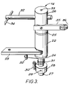
- the inboard arm 14 which is shown in more detail in Figure 3 comprises a rotary bearing body 22 which is mounted on the carriage plate 9 via a plate 23.
- a bore extends through body 22 along its axis and two flanged bushes 24,25 extend into the bore from either end.
- This provides a rotary bearing for the arm carrier 26 which has a shaft portion 27 of reduced cross section extending through the support body bore.
- a spring support 28 is fixed to the lower end of the shaft 27 by means of a set screw 29 and has a post 30 for anchoring one end of a torsion spring 31 mounted around the shaft 27. The other end of the spring 31 is anchored on a post 32 which depends from plate 23. This spring 31 provides a return force for the arm as will be described later.
- a first lever arm 32 is mounted in transverse bore in the carrier 26 and its position can be set by means of a set screw 33.
- a rod 34 is longitudinally adjustably mounted in a transverse bore in the arm 32. In use this rod 34 will extend above the side rail 4 for contacting the inboard carton wall 16.
- the carrier 26 also mounts a roller support arm 35, at the opposite end of which is mounted a roller 36.
- the roller 36 is biased into contact with the side rail 4 by means of the torsion spring 31.
- the roller support arm 35 acts as a second lever arm, such that as the carriage plate 9 moves inwardly, it causes the arm carrier 26 to rotate about the bearing body 22, thereby rotating lever arm 32 and rod 34 inwardly to contact the inboard carton wall 16 thus effectively magnifying the movement of the plate 9.
- the magnitude of the movement may be varied by varying the free length of the lever arm 32 with the set screw 33.
- the spring 31 urges the arms 32 and 35 back into their original positions.
- the movement of the arm 14 can be represented by the arrows 37,38,39 shown in Figure 1.
- the outboard wall 15 to which the lid 20 of the carton is attached is distorted less than the inboard wall 16 so as to avoid later problems with closing the lid.
- the carriage plates 8,9 are first retracted outwardly, to release the gripper plungers and the arms 13,14 which resume their outward position as shown in Figure 2A.
- the carriage plates 8,9 are then moved backwardly, for example during the period that the next stacks are being filled so as to assume a position just behind the new stacks. This cycle is repeated as many times as is necessary to fill the carton.
- the invention provides a simple and effective method and apparatus for overcoming the problems of filling irregular shaped or sized stacks into cartons.
- the invention also has the advantage that it can easily be applied retroactively to existing machinery without the need for major changes to the machinery.
Landscapes
- Engineering & Computer Science (AREA)
- Mechanical Engineering (AREA)
- Container Filling Or Packaging Operations (AREA)
- Supplying Of Containers To The Packaging Station (AREA)
- Basic Packing Technique (AREA)
- Making Paper Articles (AREA)
Abstract
Description
- The present invention relates to a method and apparatus for filling cartons or similar containers with sucessive stacks of articles, according to the pre-characterising parts of claims 1 and 4. It is particularly, but not exclusively concerned with filling stacks of tea bags or similar infusion packages into cartons.
- In a typical infusion packaging machine, measured doses of tea or another infusion are deposited in two parallel rows on a first moving web of thermoplastics coated filter paper whereafter a further web is laid over the first and individual pockets of infusion formed by heat sealing the webs together. The web is then cut to form adjacent separate packages or adjacent packages joined along a perforation line. These packages then move to a collation chamber where they are stacked and from where the adjacent collated stacks are moved into a device which inserts them into the carton. This latter device usually comprises opposed vertical plates which hold the stacks between them and which are moved down together into the carton where they are moved apart to deposit the stacks, whereafter they are retracted to receive the next pair of collated stacks. The carton is then moved forwardly by a suitable conveying means in a stepwise manner, by such an amount so that when the insertion device next moves downwardly, the carton will have moved forward sufficiently for the device to deposit the next stacks just behind the first previous ones. This sequence is repeated until the carton is full, whereupon a subsequent carton is moved beneath the plates for filling, and so on. The filling process is thus fully automated.
- The respective sizes and shapes of the infusion packages and the cartons have traditionally been such that the sides of the stacks are supported to some extent by their frictional engagement with the side walls of the carton during its stepwise forward movement which is normally sufficient to prevent the stacks falling backwardly due to inertia. However, this may not be the case if for example a carton is oversize or if the infusion package is of a non rectangular shape, for example circular, which would lead to relatively poor support of the stacks by the side walls. Furthermore non-rectangular packages, for example circular packages, may be inherently less stable when stacked than rectangular packages. If a stack falls backwards into the carton, this will prevent subsequent stacks being placed satisfactorily.
- The present invention seeks to overcome these problems by providing means which give additional support to a stack of articles in a container during moving.
- From one aspect the invention provides a method of filling a carton or the like with successive stacks of articles, wherein the carton is moved forward in a stepwise manner between filling steps, and characterised in that at least one side wall of the carton is distorted inwardly immediately behind the last deposited stack during said movement to restrain said stack from tipping over as a result of such movement.
- From a second aspect the invention also provides apparatus for filling a carton or the like with successive stacks of articles, comprising means for moving a carton in a stepwise manner with respect to a filling station, characterised in that means are provided for distorting at least one side wall of the carton inwardly behind a stack during said movement so as to restrain said stack from tipping over as a result of such movement.
- The invention is particularly applicable to the filling of adjacent stacks of infusion packages into a carton but it could be equally applied to filling other articles into cartons.
- Preferably both side walls of the carton are distorted inwardly, although situations can be envisaged where only one wall need be distorted, for example if the carton is filled with a single row of stacks. Where both walls are distorted, they need not be distorted inwardly by the same amount. In fact it is preferred that a side wall to which a carton lid (if present) is attached is distorted least so as to avoid later problems with closing the lid.
- The carton walls may be distorted inwardly by arms or plungers arranged on either side of the carton which move with a reciprocating rectilinear or pivoting inward movement or indeed a combination of such movements. For example one arm may move with a rectilinear movement while the other pivots. Both arms would then move forwardly with the carton, retract outwardly so as to release the side walls, and then move backwards to their original positions to commence another cycle.
- In a preferred embodiment the stepwise movement of the cartons is caused by a reciprocating conveying means adapted to grip the carton during forward movement thereof and to release it during each movement of the conveying means rearward, and the means for distorting the side wall(s) of the carton is carried by the conveying means and operates synchronously therewith. For example, in machines for filling stacks of infusion packages, it is normal to provide a pair of spring loaded plungers which act to grip the carton and move it in the above mentioned stepwise manner. Each plunger is normally mounted on a carriage which is reciprocated by suitable actuators in an inward and outward manner to effect the gripping and also longitudinally to effect the forward and backward movement. In a preferred embodiment, the arms for distorting the carton walls are mounted on the same carriages as these plungers to avoid the need for additional actuators.
- In a preferred embodiment one arm, at the side of the carton to which the lid is attached, is mounted on the carriage so as that its inward motion is rectilinear, and it effects the same magnitude of inward movement as the carriage. The arm at the other side of the carton however is mounted so that it magnifies the inward movement of the carriage and effects a larger distortion on the carton wall for the reasons mentioned above. This may be achieved by pivotally mounting the arm on the carriage such that as the carriage moves inwardly, the arm not only moves inwardly as a whole but also pivots about an axis, thereby producing a magnified movement.
- In a preferred embodiment, this is achieved through a first lever arm having means for engaging a carton wall being mounted on a carrier which is rotatably mounted with respect to the carriage and which also mounts a second lever arm which engages a fixed rail at the side of the carton track. Preferably the end of the lever arm is provided with a roller for engaging the rail, so as to reduce friction as the arm moves longitudinally along the rail during the forward and backward movement of the carriage. The second lever arm is preferably biased into engagement with the rail by suitable spring means. As the carriage moves inwardly, the second lever arm pivots the carrier and thus the first lever arm by virtue of its continued engagement with the fixed rail.
- The size of the movement can be varied by varying the length of the first lever arm from the pivot point of the carrier to the portion which contacts the carton wall.
- As mentioned above, the invention is particularly suitable for filling infusion packages into a carton. From another broad aspect, therefore, the invention provides a method of filling a carton or the like with successive stacks of infusion packages wherein the carton is moved in a stepwise manner between filling steps characterised in that a said stack is prevented from tipping over during such movement by means which cooperates with the stack, such means being operated synchronously with the means for moving the carton so as to move forward with the carton during its stepwise movement (claim 17).
- A preferred embodiment of the invention will now be described, by way of example only, with reference to the accompanying drawings in which:
- Figure 1 shows a perspective view of apparatus embodying the invention;
- Figures 2a and 2b shows schematically two steps in the operation of the apparatus; and
- Figure 3 shows an element of the apparatus in more detail.
- Referring to Figure 1, there is shown apparatus for filling stacks of circular tea bags or other infusion packages into cartons. An empty carton 1 moves in a stepwise manner along a
bed 2 in a channel defined by twoside rails 3,4 and under a filling device 5. Thelid 20 of the carton is at the "outboard" side of the machine so as not to be entangled with other parts of the machine. Two adjacent stacks of tea bags (not shown) are fed to the filling device 5 from a collating device in a conventional manner which need not be described in detail here. When the front of the carton 1 has moved into registry under the filling device 5, the latter moves down into the carton 1 and deposits the stacks side by side therein. The device 5 then withdraws from the carton. Such a condition is shown in Fig. 2a, with two stacks oftea bags - The carton 1 is then moved forward in a stepwise manner by an amount just greater than the tea bag diameter so that the next stacks (not shown) will be deposited in the carton just behind the
stacks carriage plates 8,9 which move inwardly so as to allow the plungers to grip the lower part of the carton 1 through thecut outs 10,11 formed in theside rails 3,4. Once the plungers have gripped the carton, theplates 8,9 are moved forward by the required amount at which point they react outwardly to release the carton 1 and then move back along the direction of thebed 2 to their original position. Thecarriage plates 8,9 are moved by suitable actuators (only the upper part of one of which 12 is shown). - The
plates 8,9 also mountarms rails 3,4 and which act to distort thewalls outboard arm 13 consists merely of anupright pillar 17 mounted onto thecarriage plate 8 and anarm member 18 which is bent at one end for engagement with the upper part of thecarton wall 15. Being directly mounted to thecarriage plate 8, thearm 13 will reciprocate retilinearly as shown byarrows - The
inboard arm 14 which is shown in more detail in Figure 3 comprises a rotary bearingbody 22 which is mounted on the carriage plate 9 via aplate 23. A bore extends throughbody 22 along its axis and twoflanged bushes 24,25 extend into the bore from either end. This provides a rotary bearing for thearm carrier 26 which has a shaft portion 27 of reduced cross section extending through the support body bore. Aspring support 28 is fixed to the lower end of the shaft 27 by means of aset screw 29 and has apost 30 for anchoring one end of atorsion spring 31 mounted around the shaft 27. The other end of thespring 31 is anchored on apost 32 which depends fromplate 23. Thisspring 31 provides a return force for the arm as will be described later. - A
first lever arm 32 is mounted in transverse bore in thecarrier 26 and its position can be set by means of aset screw 33. Arod 34 is longitudinally adjustably mounted in a transverse bore in thearm 32. In use thisrod 34 will extend above the side rail 4 for contacting theinboard carton wall 16. - The
carrier 26 also mounts aroller support arm 35, at the opposite end of which is mounted aroller 36. Theroller 36 is biased into contact with the side rail 4 by means of thetorsion spring 31. Theroller support arm 35 acts as a second lever arm, such that as the carriage plate 9 moves inwardly, it causes thearm carrier 26 to rotate about the bearingbody 22, thereby rotatinglever arm 32 androd 34 inwardly to contact theinboard carton wall 16 thus effectively magnifying the movement of the plate 9. The magnitude of the movement may be varied by varying the free length of thelever arm 32 with theset screw 33. As the carriage plate 9 retracts outwardly, thespring 31 urges thearms arm 14 can be represented by thearrows - A single cycle of operation will now be described. Initially the
arms tea bags carriage plates 8,9 then move inwardly so that the carton gripper plungers grip the carton for movement to the next position but also to move thearms outboard arm 13 moves rectilinearly inwardly while theinboard arm 14 performs a combined rectilinear and pivotal movement as described above. The effect of this movement is to distort thewalls stacks stacks outboard wall 15 to which thelid 20 of the carton is attached is distorted less than theinboard wall 16 so as to avoid later problems with closing the lid. - When the apparatus has assumed the position shown in Figure 2b, the
carriage plates 8,9 are moved forward by an appropriate amount, to transfer the carton to its next filling position. Thearms roller 36 rolls along the side rail 4 during the forward movement. - When the transfer movement is complete, the
carriage plates 8,9 are first retracted outwardly, to release the gripper plungers and thearms carriage plates 8,9 are then moved backwardly, for example during the period that the next stacks are being filled so as to assume a position just behind the new stacks. This cycle is repeated as many times as is necessary to fill the carton. - It can thus be seen that at least in its preferred forms, the invention provides a simple and effective method and apparatus for overcoming the problems of filling irregular shaped or sized stacks into cartons. The invention also has the advantage that it can easily be applied retroactively to existing machinery without the need for major changes to the machinery.
- It will of course be obvious to a person skilled in the art that the above description is only for the purposes of illustration and that many variations falling within the scope of the claims can easily be envisaged. For example if it is required to distort only one wall of the carton, one of the distorting arms may be dispensed with. It will also be appreciated that an arm mechanism other than that specifically described above may be employed, for example a pneumatic piston. Also while it is preferred that the arms are mounted on the reciprocating gripping carriages of the apparatus, this is not essential.
Claims (17)
- A method of filling a carton (1) or the like with successive stacks of articles (6,7), wherein the carton is moved forward in a stepwise manner between filling steps, and characterised in that at least one side wall (16) of the carton is distorted inwardly immediately behind the last deposited stack during said movement to restrain said stack from tipping over as a result of such movement.
- A method as claimed in claim 1 characterised in that both side walls (15,16) of the carton (1) are distorted inwardly.
- A method as claimed in claim 2 characterised in that the side walls (15,16) are not distorted inwardly by the same amount.
- Apparatus for filling a carton (1) or the like with successive stacks of articles (6,7), comprising means for moving a carton in a stepwise manner with respect to a filling station (5), characterised in that means (13,14) are provided for distorting at least one side wall (16) of the carton inwardly behind a stack during said movement so as to restrain said stack from tipping over as a result of such movement.
- Apparatus as claimed in claim 4 characterised in that means are provided for distorting both side walls (15,16) inwardly.
- Apparatus as claimed in claim 5 characterised in that said means distort said walls (15,16) by different amounts.
- Apparatus as claimed in any of claims 4 to 6 characterised in that said distortion means comprises an arm or arms (13,14) reciprocating rectilinearly or with a pivoting inward movement or a combination of such movements.
- Apparatus as claimed in any of claims 4 to 7 characterised in that the stepwise movement of the cartons is caused by a reciprocating conveying means adapted to grip the carton (1) during forward movement thereof and to release it during each movement of the conveying means rearward, and the means for distorting the side wall(s) (15,16) of the carton is carried by the conveying means and operates synchronously therewith.
- Apparatus as claimed in claim 8 characterised in that said gripping means are mounted on carriages (8,9) reciprocated by suitable actuators in an inward and outward manner to effect the gripping and also longitudinally to effect the forward and backward movement.
- Apparatus as claimed in claim 9 as dependent upon claims 8 and 7 characterised in that said arm or arms (13,14) for distorting the carton wall(s) is or are mounted on the same carriage or carriages (8,9) as the gripping means.
- Apparatus as claimed in claim 10 characterised in that a said arm (13) is mounted on a said carriage (8) so that its inward motion is rectilinear, to effect the same magnitude of inward movement as the carriage.
- Apparatus as claimed in claim 10 or 11 characterised in that a said arm (14) is mounted or a said carriage (9) so that it magnifies the inward movement of the carriage and effects a larger distortion of the carton wall (16).
- Apparatus as claimed in claim 12 characterised in that said arm (1A) mounted for magnifying the inward movement of the carriage comprises a first lever arm (32) having means (34) for engaging a carton wall (16) being mounted on a carrier (22) which is rotatably mounted with respect to the carriage (9) and which also mounts a second lever arm (35) which engages a fixed rail (4) at the side of the carton track.
- Apparatus as claimed in claim 13 characterised in that the end of the second lever arm (35) is provided with a roller (36) for engaging the rail.
- Apparatus as claimed in claim 13 or 14 characterised in that said second lever arm (35) is biased into engagement with the rail by spring means (31).
- The use of apparatus as claimed in any of claims 4 to 15 for filling a carton or the like with successive stacks of articles.
- A method of filling a carton (1) or the like with successive stacks (6,7) of infusion packages wherein the carton is moved in a stepwise manner between filling steps characterised in that a said stack is prevented from tipping over during such movement by means (13,14) which cooperates with the stack, such means being operated synchronously with the means for moving the carton, so as to move forward with said carton during its stepwise movement.
Applications Claiming Priority (2)
| Application Number | Priority Date | Filing Date | Title |
|---|---|---|---|
| GB8921760 | 1989-09-27 | ||
| GB898921760A GB8921760D0 (en) | 1989-09-27 | 1989-09-27 | Method and apparatus for filling cartons |
Publications (2)
| Publication Number | Publication Date |
|---|---|
| EP0445272A1 EP0445272A1 (en) | 1991-09-11 |
| EP0445272B1 true EP0445272B1 (en) | 1993-12-08 |
Family
ID=10663660
Family Applications (1)
| Application Number | Title | Priority Date | Filing Date |
|---|---|---|---|
| EP90914555A Expired - Lifetime EP0445272B1 (en) | 1989-09-27 | 1990-09-13 | Method and apparatus for filling cartons |
Country Status (15)
| Country | Link |
|---|---|
| US (1) | US5140803A (en) |
| EP (1) | EP0445272B1 (en) |
| CN (1) | CN1050523A (en) |
| AT (1) | ATE98176T1 (en) |
| AU (1) | AU634589B2 (en) |
| CA (1) | CA2042371A1 (en) |
| DE (1) | DE69005098T2 (en) |
| DK (1) | DK0445272T3 (en) |
| ES (1) | ES2047344T3 (en) |
| GB (1) | GB8921760D0 (en) |
| IE (1) | IE65508B1 (en) |
| IT (1) | IT1242352B (en) |
| NZ (1) | NZ235443A (en) |
| WO (1) | WO1991004911A1 (en) |
| ZA (1) | ZA907432B (en) |
Families Citing this family (6)
| Publication number | Priority date | Publication date | Assignee | Title |
|---|---|---|---|---|
| BR112013028448B1 (en) | 2011-05-06 | 2020-07-21 | Graphic Packaging International, Llc | method of forming a cardboard box |
| ES2567472T3 (en) | 2011-10-19 | 2016-04-22 | Graphic Packaging International, Inc. | System and procedure to activate the protection features of the items in a cardboard box |
| CN103419974B (en) * | 2012-05-17 | 2015-01-21 | 达和机械(昆山)有限公司 | Compacting device of food packaging machine |
| US9840358B2 (en) | 2013-03-14 | 2017-12-12 | Graphic Packaging International, Inc. | Carton with article protection feature |
| US9701436B2 (en) | 2013-04-10 | 2017-07-11 | Graphic Packaging International, Inc. | Carton with article protection feature |
| BR112015025302B1 (en) | 2013-04-10 | 2022-06-07 | Graphic Packaging International, Llc | Package for housing at least one article, die for forming a package for housing at least one article, package for housing at least one article, matrix for forming a package, and method for forming a package |
Family Cites Families (6)
| Publication number | Priority date | Publication date | Assignee | Title |
|---|---|---|---|---|
| US1345926A (en) * | 1919-01-17 | 1920-07-06 | Arthur W Harris | Carton-packing mechanism |
| US2524032A (en) * | 1945-06-07 | 1950-10-03 | Interstate Folding Box Co | Sealing method for cartons |
| US3485008A (en) * | 1967-01-04 | 1969-12-23 | Stanley Milton Silver | Method of forming cartons |
| US3443355A (en) * | 1967-02-03 | 1969-05-13 | Owens Illinois Inc | Case packing apparatus |
| US4285185A (en) * | 1979-08-29 | 1981-08-25 | Certipak Corporation | Article carrier feeding and control apparatus |
| US4433526A (en) * | 1981-04-08 | 1984-02-28 | Ex-Cell-O Corporation | Packaging machine |
-
1989
- 1989-09-27 GB GB898921760A patent/GB8921760D0/en active Pending
-
1990
- 1990-09-13 US US07/689,795 patent/US5140803A/en not_active Expired - Fee Related
- 1990-09-13 AT AT90914555T patent/ATE98176T1/en active
- 1990-09-13 AU AU64408/90A patent/AU634589B2/en not_active Ceased
- 1990-09-13 EP EP90914555A patent/EP0445272B1/en not_active Expired - Lifetime
- 1990-09-13 DE DE90914555T patent/DE69005098T2/en not_active Expired - Fee Related
- 1990-09-13 ES ES90914555T patent/ES2047344T3/en not_active Expired - Lifetime
- 1990-09-13 CA CA002042371A patent/CA2042371A1/en not_active Abandoned
- 1990-09-13 DK DK90914555.9T patent/DK0445272T3/en active
- 1990-09-13 WO PCT/GB1990/001414 patent/WO1991004911A1/en not_active Ceased
- 1990-09-18 ZA ZA907432A patent/ZA907432B/en unknown
- 1990-09-25 NZ NZ235443A patent/NZ235443A/en unknown
- 1990-09-26 IE IE345890A patent/IE65508B1/en not_active IP Right Cessation
- 1990-09-26 IT IT48311A patent/IT1242352B/en active IP Right Grant
- 1990-09-27 CN CN90108046A patent/CN1050523A/en active Pending
Also Published As
| Publication number | Publication date |
|---|---|
| WO1991004911A1 (en) | 1991-04-18 |
| DE69005098T2 (en) | 1994-04-21 |
| EP0445272A1 (en) | 1991-09-11 |
| DK0445272T3 (en) | 1994-02-14 |
| US5140803A (en) | 1992-08-25 |
| CN1050523A (en) | 1991-04-10 |
| IE903458A1 (en) | 1991-07-17 |
| CA2042371A1 (en) | 1991-03-28 |
| ATE98176T1 (en) | 1993-12-15 |
| NZ235443A (en) | 1993-02-25 |
| IT9048311A0 (en) | 1990-09-26 |
| ES2047344T3 (en) | 1994-02-16 |
| AU634589B2 (en) | 1993-02-25 |
| DE69005098D1 (en) | 1994-01-20 |
| GB8921760D0 (en) | 1989-11-08 |
| ZA907432B (en) | 1991-08-28 |
| IT9048311A1 (en) | 1992-03-26 |
| IE65508B1 (en) | 1995-11-01 |
| IT1242352B (en) | 1994-03-04 |
| AU6440890A (en) | 1991-04-28 |
Similar Documents
| Publication | Publication Date | Title |
|---|---|---|
| US4018031A (en) | Article packaging machine | |
| CA1113053A (en) | Method and apparatus for automatic filling of bags | |
| US3908340A (en) | Apparatus for feeding and applying individual lids to containers | |
| CA2255090C (en) | Process and apparatus for handling, in particular, soft film packs | |
| US4173106A (en) | Carton forming method | |
| AU2003238542A1 (en) | Device for guiding objects into containers | |
| DE60206546T2 (en) | Continuous bag filling machine with a device for feeding empty bags and a device for removing filled bags | |
| US5271208A (en) | Method and apparatus for picking up and reshaping a fluid filled bag | |
| US3710543A (en) | Arrangement for depositing objects in a receptacle | |
| US4840016A (en) | Paper bag feeder for bag-filling operations and process | |
| US7607282B2 (en) | Machine for automated packaging of products(s) in a cardboard box | |
| EP0188493A1 (en) | Improvements in or relating to packaging machines. | |
| AU634589B2 (en) | Method and apparatus for filling cartons | |
| US4224781A (en) | Apparatus for handling of unsealed slit boxes | |
| CN108298133B (en) | Method for transferring blister packs | |
| JPS60158014A (en) | Packer for cigarette, etc. | |
| US3914921A (en) | High speed carton casing apparatus | |
| JPH0285113A (en) | Device for forming fixed number of slide fastener to bundle | |
| US4024693A (en) | Carton forming apparatus | |
| US4513559A (en) | Bag transporter, folder and loader and method for operation | |
| US5662454A (en) | Device for automatically filling a container for collecting flat objects | |
| US2826881A (en) | Packaging machine | |
| EP0846073B1 (en) | Inserter apparatus | |
| WO2002012069A1 (en) | System and method for including inserts with goods during automated packaging | |
| RU1782870C (en) | Automatic line packing piece products in cardboard packs |
Legal Events
| Date | Code | Title | Description |
|---|---|---|---|
| PUAI | Public reference made under article 153(3) epc to a published international application that has entered the european phase |
Free format text: ORIGINAL CODE: 0009012 |
|
| AK | Designated contracting states |
Kind code of ref document: A1 Designated state(s): AT BE CH DE DK ES FR GB IT LI LU NL SE |
|
| 17P | Request for examination filed |
Effective date: 19911004 |
|
| 17Q | First examination report despatched |
Effective date: 19920731 |
|
| GRAA | (expected) grant |
Free format text: ORIGINAL CODE: 0009210 |
|
| AK | Designated contracting states |
Kind code of ref document: B1 Designated state(s): AT BE CH DE DK ES FR GB IT LI LU NL SE |
|
| REF | Corresponds to: |
Ref document number: 98176 Country of ref document: AT Date of ref document: 19931215 Kind code of ref document: T |
|
| REF | Corresponds to: |
Ref document number: 69005098 Country of ref document: DE Date of ref document: 19940120 |
|
| ET | Fr: translation filed | ||
| REG | Reference to a national code |
Ref country code: DK Ref legal event code: T3 |
|
| REG | Reference to a national code |
Ref country code: ES Ref legal event code: FG2A Ref document number: 2047344 Country of ref document: ES Kind code of ref document: T3 |
|
| ITF | It: translation for a ep patent filed | ||
| PLBE | No opposition filed within time limit |
Free format text: ORIGINAL CODE: 0009261 |
|
| STAA | Information on the status of an ep patent application or granted ep patent |
Free format text: STATUS: NO OPPOSITION FILED WITHIN TIME LIMIT |
|
| 26N | No opposition filed | ||
| EAL | Se: european patent in force in sweden |
Ref document number: 90914555.9 |
|
| PGFP | Annual fee paid to national office [announced via postgrant information from national office to epo] |
Ref country code: DK Payment date: 19950823 Year of fee payment: 6 |
|
| PGFP | Annual fee paid to national office [announced via postgrant information from national office to epo] |
Ref country code: SE Payment date: 19950828 Year of fee payment: 6 |
|
| PGFP | Annual fee paid to national office [announced via postgrant information from national office to epo] |
Ref country code: LU Payment date: 19950901 Year of fee payment: 6 |
|
| PGFP | Annual fee paid to national office [announced via postgrant information from national office to epo] |
Ref country code: GB Payment date: 19950904 Year of fee payment: 6 |
|
| PGFP | Annual fee paid to national office [announced via postgrant information from national office to epo] |
Ref country code: CH Payment date: 19950912 Year of fee payment: 6 Ref country code: BE Payment date: 19950912 Year of fee payment: 6 |
|
| PGFP | Annual fee paid to national office [announced via postgrant information from national office to epo] |
Ref country code: ES Payment date: 19950915 Year of fee payment: 6 |
|
| PGFP | Annual fee paid to national office [announced via postgrant information from national office to epo] |
Ref country code: FR Payment date: 19950918 Year of fee payment: 6 |
|
| PGFP | Annual fee paid to national office [announced via postgrant information from national office to epo] |
Ref country code: NL Payment date: 19950929 Year of fee payment: 6 Ref country code: DE Payment date: 19950929 Year of fee payment: 6 |
|
| ITTA | It: last paid annual fee | ||
| PGFP | Annual fee paid to national office [announced via postgrant information from national office to epo] |
Ref country code: AT Payment date: 19950930 Year of fee payment: 6 |
|
| PG25 | Lapsed in a contracting state [announced via postgrant information from national office to epo] |
Ref country code: LU Free format text: LAPSE BECAUSE OF NON-PAYMENT OF DUE FEES Effective date: 19960913 Ref country code: GB Effective date: 19960913 Ref country code: DK Effective date: 19960913 Ref country code: AT Effective date: 19960913 |
|
| REG | Reference to a national code |
Ref country code: DK Ref legal event code: EBP |
|
| PG25 | Lapsed in a contracting state [announced via postgrant information from national office to epo] |
Ref country code: SE Effective date: 19960914 Ref country code: ES Free format text: LAPSE BECAUSE OF EXPIRATION OF PROTECTION Effective date: 19960914 |
|
| PG25 | Lapsed in a contracting state [announced via postgrant information from national office to epo] |
Ref country code: LI Effective date: 19960930 Ref country code: FR Effective date: 19960930 Ref country code: CH Effective date: 19960930 Ref country code: BE Effective date: 19960930 |
|
| BERE | Be: lapsed |
Owner name: A.G. (PATENTS) LTD Effective date: 19960930 |
|
| PG25 | Lapsed in a contracting state [announced via postgrant information from national office to epo] |
Ref country code: NL Effective date: 19970401 |
|
| GBPC | Gb: european patent ceased through non-payment of renewal fee |
Effective date: 19960913 |
|
| REG | Reference to a national code |
Ref country code: CH Ref legal event code: PL |
|
| NLV4 | Nl: lapsed or anulled due to non-payment of the annual fee |
Effective date: 19970401 |
|
| PG25 | Lapsed in a contracting state [announced via postgrant information from national office to epo] |
Ref country code: DE Effective date: 19970603 |
|
| EUG | Se: european patent has lapsed |
Ref document number: 90914555.9 |
|
| REG | Reference to a national code |
Ref country code: FR Ref legal event code: ST |
|
| REG | Reference to a national code |
Ref country code: FR Ref legal event code: ST |
|
| REG | Reference to a national code |
Ref country code: ES Ref legal event code: FD2A Effective date: 19990601 |
|
| PG25 | Lapsed in a contracting state [announced via postgrant information from national office to epo] |
Ref country code: IT Free format text: LAPSE BECAUSE OF NON-PAYMENT OF DUE FEES Effective date: 20050913 |