EP0445130B1 - Improved integrated three-way and isolation solenoid valve - Google Patents
Improved integrated three-way and isolation solenoid valve Download PDFInfo
- Publication number
- EP0445130B1 EP0445130B1 EP89911715A EP89911715A EP0445130B1 EP 0445130 B1 EP0445130 B1 EP 0445130B1 EP 89911715 A EP89911715 A EP 89911715A EP 89911715 A EP89911715 A EP 89911715A EP 0445130 B1 EP0445130 B1 EP 0445130B1
- Authority
- EP
- European Patent Office
- Prior art keywords
- valve
- inlet
- fluid
- passage
- valve element
- Prior art date
- Legal status (The legal status is an assumption and is not a legal conclusion. Google has not performed a legal analysis and makes no representation as to the accuracy of the status listed.)
- Expired - Lifetime
Links
- 238000002955 isolation Methods 0.000 title description 10
- 239000012530 fluid Substances 0.000 claims abstract description 76
- 230000004044 response Effects 0.000 claims description 7
- 230000000694 effects Effects 0.000 abstract description 5
- 230000008901 benefit Effects 0.000 description 2
- 230000002411 adverse Effects 0.000 description 1
- 238000006073 displacement reaction Methods 0.000 description 1
- 230000007246 mechanism Effects 0.000 description 1
- 230000009467 reduction Effects 0.000 description 1
Images
Classifications
-
- B—PERFORMING OPERATIONS; TRANSPORTING
- B60—VEHICLES IN GENERAL
- B60T—VEHICLE BRAKE CONTROL SYSTEMS OR PARTS THEREOF; BRAKE CONTROL SYSTEMS OR PARTS THEREOF, IN GENERAL; ARRANGEMENT OF BRAKING ELEMENTS ON VEHICLES IN GENERAL; PORTABLE DEVICES FOR PREVENTING UNWANTED MOVEMENT OF VEHICLES; VEHICLE MODIFICATIONS TO FACILITATE COOLING OF BRAKES
- B60T8/00—Arrangements for adjusting wheel-braking force to meet varying vehicular or ground-surface conditions, e.g. limiting or varying distribution of braking force
- B60T8/32—Arrangements for adjusting wheel-braking force to meet varying vehicular or ground-surface conditions, e.g. limiting or varying distribution of braking force responsive to a speed condition, e.g. acceleration or deceleration
- B60T8/34—Arrangements for adjusting wheel-braking force to meet varying vehicular or ground-surface conditions, e.g. limiting or varying distribution of braking force responsive to a speed condition, e.g. acceleration or deceleration having a fluid pressure regulator responsive to a speed condition
- B60T8/50—Arrangements for adjusting wheel-braking force to meet varying vehicular or ground-surface conditions, e.g. limiting or varying distribution of braking force responsive to a speed condition, e.g. acceleration or deceleration having a fluid pressure regulator responsive to a speed condition having means for controlling the rate at which pressure is reapplied to or released from the brake
-
- B—PERFORMING OPERATIONS; TRANSPORTING
- B60—VEHICLES IN GENERAL
- B60T—VEHICLE BRAKE CONTROL SYSTEMS OR PARTS THEREOF; BRAKE CONTROL SYSTEMS OR PARTS THEREOF, IN GENERAL; ARRANGEMENT OF BRAKING ELEMENTS ON VEHICLES IN GENERAL; PORTABLE DEVICES FOR PREVENTING UNWANTED MOVEMENT OF VEHICLES; VEHICLE MODIFICATIONS TO FACILITATE COOLING OF BRAKES
- B60T15/00—Construction arrangement, or operation of valves incorporated in power brake systems and not covered by groups B60T11/00 or B60T13/00
- B60T15/02—Application and release valves
- B60T15/025—Electrically controlled valves
- B60T15/028—Electrically controlled valves in hydraulic systems
-
- B—PERFORMING OPERATIONS; TRANSPORTING
- B60—VEHICLES IN GENERAL
- B60T—VEHICLE BRAKE CONTROL SYSTEMS OR PARTS THEREOF; BRAKE CONTROL SYSTEMS OR PARTS THEREOF, IN GENERAL; ARRANGEMENT OF BRAKING ELEMENTS ON VEHICLES IN GENERAL; PORTABLE DEVICES FOR PREVENTING UNWANTED MOVEMENT OF VEHICLES; VEHICLE MODIFICATIONS TO FACILITATE COOLING OF BRAKES
- B60T13/00—Transmitting braking action from initiating means to ultimate brake actuator with power assistance or drive; Brake systems incorporating such transmitting means, e.g. air-pressure brake systems
- B60T13/10—Transmitting braking action from initiating means to ultimate brake actuator with power assistance or drive; Brake systems incorporating such transmitting means, e.g. air-pressure brake systems with fluid assistance, drive, or release
- B60T13/66—Electrical control in fluid-pressure brake systems
- B60T13/68—Electrical control in fluid-pressure brake systems by electrically-controlled valves
- B60T13/686—Electrical control in fluid-pressure brake systems by electrically-controlled valves in hydraulic systems or parts thereof
-
- B—PERFORMING OPERATIONS; TRANSPORTING
- B60—VEHICLES IN GENERAL
- B60T—VEHICLE BRAKE CONTROL SYSTEMS OR PARTS THEREOF; BRAKE CONTROL SYSTEMS OR PARTS THEREOF, IN GENERAL; ARRANGEMENT OF BRAKING ELEMENTS ON VEHICLES IN GENERAL; PORTABLE DEVICES FOR PREVENTING UNWANTED MOVEMENT OF VEHICLES; VEHICLE MODIFICATIONS TO FACILITATE COOLING OF BRAKES
- B60T8/00—Arrangements for adjusting wheel-braking force to meet varying vehicular or ground-surface conditions, e.g. limiting or varying distribution of braking force
- B60T8/32—Arrangements for adjusting wheel-braking force to meet varying vehicular or ground-surface conditions, e.g. limiting or varying distribution of braking force responsive to a speed condition, e.g. acceleration or deceleration
- B60T8/34—Arrangements for adjusting wheel-braking force to meet varying vehicular or ground-surface conditions, e.g. limiting or varying distribution of braking force responsive to a speed condition, e.g. acceleration or deceleration having a fluid pressure regulator responsive to a speed condition
- B60T8/36—Arrangements for adjusting wheel-braking force to meet varying vehicular or ground-surface conditions, e.g. limiting or varying distribution of braking force responsive to a speed condition, e.g. acceleration or deceleration having a fluid pressure regulator responsive to a speed condition including a pilot valve responding to an electromagnetic force
- B60T8/3615—Electromagnetic valves specially adapted for anti-lock brake and traction control systems
-
- G—PHYSICS
- G01—MEASURING; TESTING
- G01N—INVESTIGATING OR ANALYSING MATERIALS BY DETERMINING THEIR CHEMICAL OR PHYSICAL PROPERTIES
- G01N30/00—Investigating or analysing materials by separation into components using adsorption, absorption or similar phenomena or using ion-exchange, e.g. chromatography or field flow fractionation
- G01N30/02—Column chromatography
- G01N2030/022—Column chromatography characterised by the kind of separation mechanism
- G01N2030/025—Gas chromatography
-
- Y—GENERAL TAGGING OF NEW TECHNOLOGICAL DEVELOPMENTS; GENERAL TAGGING OF CROSS-SECTIONAL TECHNOLOGIES SPANNING OVER SEVERAL SECTIONS OF THE IPC; TECHNICAL SUBJECTS COVERED BY FORMER USPC CROSS-REFERENCE ART COLLECTIONS [XRACs] AND DIGESTS
- Y10—TECHNICAL SUBJECTS COVERED BY FORMER USPC
- Y10T—TECHNICAL SUBJECTS COVERED BY FORMER US CLASSIFICATION
- Y10T137/00—Fluid handling
- Y10T137/8593—Systems
- Y10T137/86493—Multi-way valve unit
- Y10T137/86574—Supply and exhaust
- Y10T137/86622—Motor-operated
-
- Y—GENERAL TAGGING OF NEW TECHNOLOGICAL DEVELOPMENTS; GENERAL TAGGING OF CROSS-SECTIONAL TECHNOLOGIES SPANNING OVER SEVERAL SECTIONS OF THE IPC; TECHNICAL SUBJECTS COVERED BY FORMER USPC CROSS-REFERENCE ART COLLECTIONS [XRACs] AND DIGESTS
- Y10—TECHNICAL SUBJECTS COVERED BY FORMER USPC
- Y10T—TECHNICAL SUBJECTS COVERED BY FORMER US CLASSIFICATION
- Y10T137/00—Fluid handling
- Y10T137/8593—Systems
- Y10T137/87169—Supply and exhaust
- Y10T137/87217—Motor
Definitions
- the present invention relates to valves for controlling the flow of a fluid such as hydraulic brake fluid, and particularly to a solenoid actuated valve which functions both as a three-way valve and as an isolation valve, such a valve having particularly advantageous application in an anti-lock braking system.
- a further improved valve which is not subject to sudden high pressure increases from the master cylinder which may result from a spike application of the brakes and which can cause first valve means therein to be moved to a position where fluid flow is through an orifice restriction. It is also desirable to provide a solenoid actuated valve wherein the movement of the first valve means will provide isolation of fluid flow from the master cylinder so that a check valve in a fluid flow line from the master cylinder may be eliminated. It is also desirable to provide a solenoid actuated valve wherein a bypass line with a check valve may be eliminated so that during the release phase of braking the valve permits return flow to the master cylinder without the need of such bypass line and check valve. Finally, it is desirable to provide a solenoid actuated valve which shuttles reliably as predicted.
- a control valve comprising a valve body having a bore and a first inlet, second inlet, a first outlet, and a decay outlet, first valve means received reciprocally in said bore and having a longitudinal through passage therethrough communicating between said second inlet and said outlets, second valve means normally closing said decay outlet and displacable to an open position and further to cooperate with said longitudinal through passage and thereby cause a fluid pressure differential across said first valve means, a transverse opening extending through said first valve means to intersect said longitudinal through passage and provide communication between said first inlet and the outlets, said first valve means being moveable in response to the fluid pressure differential thereacross to be displacable to a displaced position wherein flow between said first inlet and said transverse passage is terminated so that fluid may flow between said second inlet and outlets, and actuator means for moving said second valve means from a closed position to an open position in response to said control signals.
- Valve assembly 12 includes a valve body 16 having a cylindrical stepped bore 18.
- Stepped bore 18 includes a reduced diameter section 20 which communicates with an enlarged diameter section 22.
- Located between the reduced and enlarged diameter sections is a shoulder 24.
- a first inlet 30 communicates fluid pressure from a master cylinder (not shown) and a second inlet 40 receives fluid pressure from a pump (not shown). Each of the inlets communicates with the enlarged diameter section 22.
- Second inlet 40 includes a one-way flow valve means or check valve 45.
- a first outlet 50 communicates the reduced diameter section 18 with a wheel brake (not shown), and a decay outlet 60 communicates the reduced diameter section with a decay circuit of an anti-lock braking system (not shown). Decay outlet 60 provides a decay valve seat 62.
- a first valve element 31 Received within stepped bore 18 is a first valve element 31 which includes a reduced diameter section 34 and an enlarged diameter section 32. Disposed about enlarged diameter section 32 may be a seal 33. Extending longitudinally through valve element 31 is a longitudinal through passage 35 which terminates in a valve seat 36 at one end of the first valve element. Disposed within longitudinal through passage 35 is a fluid flow restriction 43.
- a second valve element 70 which is biased by resilient means 80 extending between second valve element 70 and a shoulder of first valve element 31.
- Valve element 70 and resilient means 80 are located in valve chamber 78.
- Extending transversely through valve element 31 is a transverse fluid passage 37 which intersects the longitudinal through passage 35 and is disposed adjacent shoulder 24.
- Transverse passage 37 communicates with a valve groove 38.
- Enlarged diameter section 22 of bore 18 defines with the enlarged diameter section 32 of first valve element 31 a fluid receiving chamber 44 which communicates with the second or pump inlet 40.
- Enlarged diameter sections 22, 32, and shoulder 24 define a fluid receiving chamber 39 which communicates with the first or master cylinder inlet 30.
- Fluid receiving chamber 39 communicates, during normal braking, with groove 38 and transverse fluid passage 37, while fluid receiving chamber 44 communicates with longitudinal through passage 35.
- the present invention provides an improved solenoid actuated valve as compared to previous systems such as that disclosed in copending Serial No. 50,350 entitled “ Anti-Lock Braking System Check Valve With Build Orifice " and assigned to the same assignee as herein, and Brown United States Patent No. 4,620,565, both the copending patent application and issued patent being incorporated herein by reference.
- fluid braking pressure is received through first inlet 30 and communicates with pressure receiving chamber 39.
- the fluid pressure is communicated through transverse fluid passage 37, longitudinal through passage 35, past valve seat 36, and through first outlet 50 to the associated wheel brake or wheel brakes.
- first valve element 31 moves upwardly in bore 18, to a position wherein shoulder 24 of stepped bore 18 closes off or substantially restricts fluid flow between fluid receiving chamber 39 and transverse fluid passage 37 (see Figure 2).
- Fluid pressure within receiving chamber 44 is communicated through longitudinal through passage 35, via restriction 43, past valve seat 36 and through first-outlet 50 to the wheel brake or wheel brakes.
- the electronic control unit signals actuator 14 which operates to displace actuator rod 15 against second valve element 70 to move element 70 downwardly toward, and in some cases into engagement with, valve seat 36.
- first valve element 31 is less than the initial available axial movement of second valve element 70 such that when valve element 31 is in its upward position, second valve element 70 is still capable of axial movement between a position closing decay port 60 and a position closing longitudinal through passage 35.
- Valve element 31 will remain in the upward position as long as the force from pressure in chamber 78 plus the force exerted by the spring 80 is less than the force exerted by pressurized fluid in pressure receiving chamber 44 when solenoid valve 14 is deenergized.
- solenoid 14 is energized, the additional force may momentarily overcome the differential pressure force. However, fluid flow is still shut off by the second valve element 70.
- Second valve element 70 may be cycled between open and closed positions as desired by means of appropriate control signals to the actuator 14.
- valve element 70 The stroke and corresponding movement of valve element 70 is reduced significantly when the valve element 31 is in its upper position. Accordingly, while response of the valve will be slower during a first cycle when valve element 31 moves from its lower to its upper position, the response by the valve will increase thereafter.
- second valve element 70 When second valve element 70 is seated against decay valve seat 62, fluid pressure will rise at a controlled rate in chamber 78 by reason of the restriction 43 within longitudinal through passage 35. If valve element 70 remains seated against decay valve seat 62, the pressure in chamber 78 will eventually reach a pressure sufficient to allow spring 80 to force first valve element 31 back to its lower position thereby reopening the transverse fluid passage 37.
- control valve of the present invention provides substantial advantages over prior control valves.
- the fluid pressure received from the master cylinder will not force first valve element 31 into a displaced position wherein fluid flow to the brakes is through an orifice restriction. Rather, the fluid pressure from the master cylinder will cause the first valve element 31 to move downwardly so that fluid may flow freely through transverse opening 37, longitudinal through opening 35, and to outlet 50.
- Prior anti-lock braking systems typically used a check valve in order to effect isolation in the circuit between the master cylinder and solenoid actuated valve mechanism so that during anti-lock braking, fluid pressure could not be transmitted to the master cylinder.
- the solenoid actuated valve accomplishes this by means of the closure of transverse fluid passage 37 so that fluid pressure from the pump received in chamber 44 is not communicated to chamber 39 and out through first inlet 30. Therefore, communication with the master cylinder is effectedly isolated during anti-lock operation. Additionally, during the release phase of braking, prior anti-lock brake circuits provided a bypass line with a check valve for return flow to the master cylinder. This has been eliminated by having the master cylinder inlet disposed separate from the pump inlet so that during the release phase of braking fluid may flow back through inlet 30 and toward the master cylinder. Also, the shuttling effect of first valve element 31 is now provided in a predictable and reliable manner.
- Control valve 10 of the present invention also may be utilized with solenoid valve 14, or it can be installed separately. Another advantage of the present invention is that in case first valve element 31 should become stuck in the isolated position (displaced upwardly), increased master cylinder pressure communicated to receiving chamber 39 will force valve element 31 to be displaced downwardly so that master cylinder communication with the brakes is open.
- the control valve of the present invention provides a one way flow valve means or check valve 45 which prevents any fluid displacement effected by the master cylinder from being communicated into the pump and accumulator circuit.
- Such a valve is important in the event of a total or partial loss of the accumulator's gas charge or a faulty check valve in the pump.
- the orifice 43 is disposed within the circuit such that it is in line with fluid flow when the pump is actuated.
- the present invention provides isolation of the master cylinder at minimal cost, and effects shuttling of the first valve element by means of the on-and-off actuation of the pump. This eliminates the prior usage of return springs which had to be balanced in order to move appropriately the valve element. Additionally, seal 33 may be provided at the enlarged diameter section 32 of valve element 31. However, other seals are not required. The diametrical clearances can provide for adequate isolation.
Landscapes
- Engineering & Computer Science (AREA)
- Physics & Mathematics (AREA)
- Transportation (AREA)
- Mechanical Engineering (AREA)
- Electromagnetism (AREA)
- Fluid Mechanics (AREA)
- Regulating Braking Force (AREA)
- Magnetically Actuated Valves (AREA)
- Fluid-Driven Valves (AREA)
- Valves And Accessory Devices For Braking Systems (AREA)
Abstract
Description
- The present invention relates to valves for controlling the flow of a fluid such as hydraulic brake fluid, and particularly to a solenoid actuated valve which functions both as a three-way valve and as an isolation valve, such a valve having particularly advantageous application in an anti-lock braking system.
- In various fluid power systems, there exists a need for controlling the application of pressurized fluid between a source of such fluid and an actuator. It has been a common practice to provide a solenoid valve and an associated control device to accomplish this purpose. One particularly relevant application of such valves is in an anti-lock braking system in which control of the application of pressurized fluid to wheel brakes (pressure build), release of pressurized brake fluid from the wheel brakes (decay), and isolation of the wheel brakes from the source of pressurized fluid (isolation) are controlled by multiple solenoid valves and an electronic control device responsive to rotational movement of a vehicle wheel. Such systems are disclosed in numerous United States patents and are now well known to those skilled in the art. It is apparent that the cost and reliability of such systems is affected adversely by a number of solenoid valves required to control the flow of braking fluid, the result of not only the number of valves required but also the number of interconnecting fluid lines, solenoid control outputs, wiring, and the like. Accordingly, it is highly desirable to develop a solenoid actuated control valve for use in pressurized fluid systems which enables a reduction of the number of solenoid valves required. Brown United States Patent No. 4,620,565 entitled "Integrated Three-Way and Isolation Solenoid Valve" and assigned to the same assignee as herein, discloses a solenoid-actuated control valve which accomplishes the desired objectives described above. However, it is desirable to provide a further improved valve which is not subject to sudden high pressure increases from the master cylinder which may result from a spike application of the brakes and which can cause first valve means therein to be moved to a position where fluid flow is through an orifice restriction. It is also desirable to provide a solenoid actuated valve wherein the movement of the first valve means will provide isolation of fluid flow from the master cylinder so that a check valve in a fluid flow line from the master cylinder may be eliminated. It is also desirable to provide a solenoid actuated valve wherein a bypass line with a check valve may be eliminated so that during the release phase of braking the valve permits return flow to the master cylinder without the need of such bypass line and check valve. Finally, it is desirable to provide a solenoid actuated valve which shuttles reliably as predicted.
- The present invention provides solutions to the above problems by disclosing a control valve comprising a valve body having a bore and a first inlet, second inlet, a first outlet, and a decay outlet, first valve means received reciprocally in said bore and having a longitudinal through passage therethrough communicating between said second inlet and said outlets, second valve means normally closing said decay outlet and displacable to an open position and further to cooperate with said longitudinal through passage and thereby cause a fluid pressure differential across said first valve means, a transverse opening extending through said first valve means to intersect said longitudinal through passage and provide communication between said first inlet and the outlets, said first valve means being moveable in response to the fluid pressure differential thereacross to be displacable to a displaced position wherein flow between said first inlet and said transverse passage is terminated so that fluid may flow between said second inlet and outlets, and actuator means for moving said second valve means from a closed position to an open position in response to said control signals.
- One way of carrying out the invention is described in detail below with reference to the drawings which illustrate an embodiment in which:
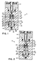
- Figure 1 illustrates the solenoid actuated valve with the present invention during normal braking; and
- Figure 2 illustrates the solenoid actuated valve during anti-lock braking operation.
- Referring now to the drawings and in particular to Figure 1, there is shown an integrated three-way and isolation solenoid valve in accordance with the present invention and indicated generally by
reference numeral 10, which includes avalve assembly 12 and asolenoid actuator 14 with anactuator rod 15.Valve assembly 12 includes avalve body 16 having acylindrical stepped bore 18. Steppedbore 18 includes a reduceddiameter section 20 which communicates with an enlargeddiameter section 22. Located between the reduced and enlarged diameter sections is ashoulder 24. Afirst inlet 30 communicates fluid pressure from a master cylinder (not shown) and asecond inlet 40 receives fluid pressure from a pump (not shown). Each of the inlets communicates with the enlargeddiameter section 22.Second inlet 40 includes a one-way flow valve means orcheck valve 45. Afirst outlet 50 communicates the reduceddiameter section 18 with a wheel brake (not shown), and adecay outlet 60 communicates the reduced diameter section with a decay circuit of an anti-lock braking system (not shown). Decayoutlet 60 provides adecay valve seat 62. Received withinstepped bore 18 is afirst valve element 31 which includes a reduceddiameter section 34 and an enlargeddiameter section 32. Disposed about enlargeddiameter section 32 may be aseal 33. Extending longitudinally throughvalve element 31 is a longitudinal throughpassage 35 which terminates in avalve seat 36 at one end of the first valve element. Disposed within longitudinal throughpassage 35 is afluid flow restriction 43. Locatedadjacent seat 36 andclosing valve seat 62 during normal braking operation, is asecond valve element 70 which is biased byresilient means 80 extending betweensecond valve element 70 and a shoulder offirst valve element 31.Valve element 70 andresilient means 80 are located invalve chamber 78. Extending transversely throughvalve element 31 is atransverse fluid passage 37 which intersects the longitudinal throughpassage 35 and is disposedadjacent shoulder 24.Transverse passage 37 communicates with a valve groove 38. Enlargeddiameter section 22 ofbore 18 defines with the enlargeddiameter section 32 of first valve element 31 afluid receiving chamber 44 which communicates with the second orpump inlet 40. Enlargeddiameter sections shoulder 24 define afluid receiving chamber 39 which communicates with the first ormaster cylinder inlet 30.Fluid receiving chamber 39 communicates, during normal braking, with groove 38 andtransverse fluid passage 37, whilefluid receiving chamber 44 communicates with longitudinal throughpassage 35. - The present invention provides an improved solenoid actuated valve as compared to previous systems such as that disclosed in copending Serial No. 50,350 entitled "Anti-Lock Braking System Check Valve With Build Orifice" and assigned to the same assignee as herein, and Brown United States Patent No. 4,620,565, both the copending patent application and issued patent being incorporated herein by reference. During normal braking operation, fluid braking pressure is received through
first inlet 30 and communicates withpressure receiving chamber 39. The fluid pressure is communicated throughtransverse fluid passage 37, longitudinal throughpassage 35,past valve seat 36, and throughfirst outlet 50 to the associated wheel brake or wheel brakes. In case of a sudden spike apply of the brakes, instead of the fluid pressure received atmaster cylinder inlet 30 causing thefirst valve element 31 to move upwardly so that fluid flow may be through an orifice restriction, which is undesirable, the sudden high fluid pressure received inchamber 39 causesfirst valve element 31 to move downwardly in Figure 1 so that fluid flow may pass freely throughtransverse passage 37, longitudinal throughpassage 35, and to the wheel brakes. During normal braking operation, thesecond valve element 70closes valve seat 62. During anti-lock brake operation, the electronic control unit (not shown) of the system will immediately activate the pump (not shown) so that fluid pressure is received through thesecond inlet 40 and intochamber 44. This causes thefirst valve element 31 to move upwardly inbore 18, to a position whereinshoulder 24 of stepped bore 18 closes off or substantially restricts fluid flow betweenfluid receiving chamber 39 and transverse fluid passage 37 (see Figure 2). Fluid pressure within receivingchamber 44 is communicated through longitudinal throughpassage 35, viarestriction 43,past valve seat 36 and through first-outlet 50 to the wheel brake or wheel brakes. This describes the pressure build mode of anti-lock braking system operation. As the anti-lock braking system determines via a wheel speed sensor or sensors that brake fluid pressure should be released from the wheel brake(s) in order to prevent wheel lockup, the electronic controlunit signals actuator 14 which operates to displaceactuator rod 15 againstsecond valve element 70 to moveelement 70 downwardly toward, and in some cases into engagement with,valve seat 36. This opensdecay outlet 60 and permits fluid pressure to flow into the decay circuit. As fluid pressure is received withinvalve chamber 78 by reason ofdecay outlet 60 being open andsecond valve 70 stopping or restricting the flow of pressurized fluid through longitudinal throughpassage 35, the fluid pressure inchamber 78 reduces to a value less than the pressure of pressurized fluid atsecond inlet 40 plus a pressure force value equal to the force exerted byspring 80 againstfirst valve element 31, and whensolenoid 14 is deenergized,first valve element 31 will slide upwardly in steppedbore 18 to bringvalve seat 36 toward engagement withsecond valve 70 to stop or restrict fluid communication between thesecond inlet 40 and theoutlet 50. The upward movement offirst valve element 31 is less than the initial available axial movement ofsecond valve element 70 such that whenvalve element 31 is in its upward position,second valve element 70 is still capable of axial movement between a positionclosing decay port 60 and a position closing longitudinal throughpassage 35.Valve element 31 will remain in the upward position as long as the force from pressure inchamber 78 plus the force exerted by thespring 80 is less than the force exerted by pressurized fluid inpressure receiving chamber 44 whensolenoid valve 14 is deenergized. Whensolenoid 14 is energized, the additional force may momentarily overcome the differential pressure force. However, fluid flow is still shut off by thesecond valve element 70.Second valve element 70 may be cycled between open and closed positions as desired by means of appropriate control signals to theactuator 14. The stroke and corresponding movement ofvalve element 70 is reduced significantly when thevalve element 31 is in its upper position. Accordingly, while response of the valve will be slower during a first cycle whenvalve element 31 moves from its lower to its upper position, the response by the valve will increase thereafter. Whensecond valve element 70 is seated againstdecay valve seat 62, fluid pressure will rise at a controlled rate inchamber 78 by reason of therestriction 43 within longitudinal throughpassage 35. Ifvalve element 70 remains seated againstdecay valve seat 62, the pressure inchamber 78 will eventually reach a pressure sufficient to allowspring 80 to forcefirst valve element 31 back to its lower position thereby reopening thetransverse fluid passage 37. - The control valve of the present invention provides substantial advantages over prior control valves. In case of a spike apply of the brakes, the fluid pressure received from the master cylinder will not force
first valve element 31 into a displaced position wherein fluid flow to the brakes is through an orifice restriction. Rather, the fluid pressure from the master cylinder will cause thefirst valve element 31 to move downwardly so that fluid may flow freely throughtransverse opening 37, longitudinal throughopening 35, and tooutlet 50. Prior anti-lock braking systems typically used a check valve in order to effect isolation in the circuit between the master cylinder and solenoid actuated valve mechanism so that during anti-lock braking, fluid pressure could not be transmitted to the master cylinder. The solenoid actuated valve accomplishes this by means of the closure oftransverse fluid passage 37 so that fluid pressure from the pump received inchamber 44 is not communicated tochamber 39 and out throughfirst inlet 30. Therefore, communication with the master cylinder is effectedly isolated during anti-lock operation. Additionally, during the release phase of braking, prior anti-lock brake circuits provided a bypass line with a check valve for return flow to the master cylinder. This has been eliminated by having the master cylinder inlet disposed separate from the pump inlet so that during the release phase of braking fluid may flow back throughinlet 30 and toward the master cylinder. Also, the shuttling effect offirst valve element 31 is now provided in a predictable and reliable manner. During anti-lock braking operation, fluid pressure is received inchamber 44 and communicated through longitudinal throughpassage 35 viarestriction 43. This effects a positive shuttle of thefirst valve element 31 in a predictable and reliable manner.Control valve 10 of the present invention also may be utilized withsolenoid valve 14, or it can be installed separately. Another advantage of the present invention is that in casefirst valve element 31 should become stuck in the isolated position (displaced upwardly), increased master cylinder pressure communicated to receivingchamber 39 will forcevalve element 31 to be displaced downwardly so that master cylinder communication with the brakes is open. The control valve of the present invention provides a one way flow valve means orcheck valve 45 which prevents any fluid displacement effected by the master cylinder from being communicated into the pump and accumulator circuit. Such a valve is important in the event of a total or partial loss of the accumulator's gas charge or a faulty check valve in the pump. Theorifice 43 is disposed within the circuit such that it is in line with fluid flow when the pump is actuated. - The present invention provides isolation of the master cylinder at minimal cost, and effects shuttling of the first valve element by means of the on-and-off actuation of the pump. This eliminates the prior usage of return springs which had to be balanced in order to move appropriately the valve element. Additionally, seal 33 may be provided at the
enlarged diameter section 32 ofvalve element 31. However, other seals are not required. The diametrical clearances can provide for adequate isolation.
Claims (10)
- A control valve (12) for use in an anti-lock braking system which includes a source of pressurized braking fluid, wheel braking means, and an anti-lock control means for generating brake controls signals in response to behavior of a wheel, comprising a valve body (16) having a bore (18) and a first inlet (30), second inlet (40), a first outlet (50), and a decay outlet (60), first valve means (31) received reciprocally in said bore (18) and having a longitudinal through passage (35) therethrough communicating between said second inlet (40) and said outlets (50, 60), second valve means (70) normally closing said decay outlet (60) and displacable to an open position and to cooperate with said longitudinal through passage (35) and thereby cause a fluid pressure differential across said first valve means (31), a transverse fluid passage (37) extending through said first valve means (31) to intersect said longitudinal through passage (35) and provide communication between said first inlet (30) and the outlets (50, 60), said first valve means (31) being moveable in response to the fluid pressure differential there-across to be displacable to a displaced position wherein flow between said first inlet (30) and said transverse fluid passage (37) is terminated and fluid may flow between said second inlet (40) and outlets (50, 60), and actuator means (14) for moving said second valve means (70) from a closed position to an open position in response to said control signals.
- The control valve in accordance with claim 1, wherein said longitudinal through passage (35) comprises restriction means (43) therein.
- The control valve in accordance with claim 1, wherein said bore (18) includes a shoulder (24) therein, said shoulder (24) comprising means for closing transverse fluid passage (37).
- The control valve in accordance with claim 1, wherein said second inlet (40) includes therein one way fluid flow valve means (45).
- The control valve in accordance with claim 4, wherein said actuator means (14) comprises an electric solenoid (14) having a plunger (15), said plunger (15) engaging said second valve element (70).
- The control valve in accordance with claim 5, wherein said longitudinal through passage (35) communicates between a valve seat (36) and an end of said valve bore (18), said valve seat (36) being positioned adjacent said second valve means (70).
- The control valve in accordance with claim 1, wherein said bore (18) comprises a stepped bore (18), said first valve means (31) having an enlarged diameter section (32) received within an enlarged diameter section (22) of said stepped bore (18), the enlarged diameter section (32) of the first valve means (31), the valve body (16), and a shoulder (24) of said stepped bore (18) defining a first receiving chamber (39) communicating with said first inlet (30).
- The control valve in accordance with claim 7, wherein during a release phase of braking, fluid may flow from said first receiving chamber (39) through said first inlet (30) and toward a master cylinder.
- The control valve in accordance with claim 8, wherein said enlarged diameter section (32) of the first valve means (30) and an end of said stepped bore (18) define therebetween a second fluid receiving chamber (44) communicating with said second inlet (40).
- The control valve in accordance with claim 1, wherein said first inlet (30) comprises a master cylinder inlet (30), said second inlet (40) comprises a pump inlet (40), and said first outlet (50) comprises an outlet (50) to said wheel braking means.
Applications Claiming Priority (2)
| Application Number | Priority Date | Filing Date | Title |
|---|---|---|---|
| US07/274,076 US4844119A (en) | 1988-11-21 | 1988-11-21 | Integrated three-way and isolation solenoid valve |
| US274076 | 1988-11-21 |
Publications (2)
| Publication Number | Publication Date |
|---|---|
| EP0445130A1 EP0445130A1 (en) | 1991-09-11 |
| EP0445130B1 true EP0445130B1 (en) | 1993-05-26 |
Family
ID=23046657
Family Applications (1)
| Application Number | Title | Priority Date | Filing Date |
|---|---|---|---|
| EP89911715A Expired - Lifetime EP0445130B1 (en) | 1988-11-21 | 1989-09-15 | Improved integrated three-way and isolation solenoid valve |
Country Status (9)
| Country | Link |
|---|---|
| US (1) | US4844119A (en) |
| EP (1) | EP0445130B1 (en) |
| JP (1) | JPH07102798B2 (en) |
| KR (1) | KR900701584A (en) |
| AU (1) | AU623318B2 (en) |
| CA (1) | CA1315177C (en) |
| DE (1) | DE68906797T2 (en) |
| ES (1) | ES2017568A6 (en) |
| WO (1) | WO1990005658A1 (en) |
Families Citing this family (30)
| Publication number | Priority date | Publication date | Assignee | Title |
|---|---|---|---|---|
| US5284392A (en) * | 1987-05-29 | 1994-02-08 | Ide Russell D | Bearings having spaced pads and methods of making the same |
| DE68900632D1 (en) * | 1988-05-10 | 1992-02-13 | Bendix Europ Services Tech | CONTROLLED VALVE FOR AN ANTI-BLOCKING SYSTEM. |
| US4972873A (en) * | 1989-06-21 | 1990-11-27 | Allied-Signal Inc. | Shuttle valve with spike-apply damping |
| US4936334A (en) * | 1989-09-29 | 1990-06-26 | Allied-Signal Inc. | Differential pressure shuttle valve |
| DE3934771C1 (en) * | 1989-10-18 | 1991-03-28 | Lucas Industries P.L.C., Birmingham, West Midlands, Gb | |
| DE3938417C1 (en) * | 1989-11-18 | 1991-03-21 | Mercedes-Benz Aktiengesellschaft, 7000 Stuttgart, De | |
| US5248191A (en) * | 1990-03-27 | 1993-09-28 | Nippondenso Co., Ltd. | Pressure control valve for continuous pressure control to wheel cylinder |
| US5172963A (en) * | 1990-08-17 | 1992-12-22 | Allied-Signal Inc. | Pressure supply valve for an adaptive braking and traction control system |
| DE4134427A1 (en) * | 1991-10-18 | 1993-04-22 | Teves Gmbh Alfred | BLOCK-PROTECTED HYDRAULIC BRAKE SYSTEM |
| DE4102626C2 (en) * | 1991-01-30 | 2001-08-09 | Bosch Gmbh Robert | Solenoid operated 2/2-way valve, especially for hydraulic motor vehicle brake systems with an anti-lock and traction control system |
| FR2674206B1 (en) * | 1991-03-20 | 1996-08-09 | Bendix Europ Services Tech | INTEGRATED PRESSURE AMPLIFICATION AND MODULATION SYSTEM FOR A HYDRAULIC CIRCUIT. |
| DE4112920A1 (en) * | 1991-04-19 | 1992-10-22 | Teves Gmbh Alfred | ELECTROMAGNETIC VALVE, ESPECIALLY FOR SLIP-CONTROLLED MOTOR VEHICLE BRAKING SYSTEMS |
| DE4134471A1 (en) * | 1991-10-18 | 1993-04-22 | Teves Gmbh Alfred | CURRENT CONTROL VALVE FOR A BLOCK-PROTECTED HYDRAULIC BRAKE SYSTEM |
| FR2683337B1 (en) * | 1991-10-31 | 1994-01-07 | Bendix Europe Services Technique | PRESSURE REGULATING DEVICE FOR HYDRAULIC CIRCUIT. |
| FR2683338B1 (en) * | 1991-10-31 | 1994-01-07 | Bendix Europe Services Technique | PRESSURE REGULATING DEVICE FOR HYDRAULIC CIRCUIT. |
| US5163474A (en) * | 1991-11-15 | 1992-11-17 | Allied-Signal Inc. | Combination solenoid valve and integral shuttle valve |
| US5299859A (en) * | 1991-11-15 | 1994-04-05 | Allied-Signal Inc. | Combination solenoid valve and shuttle valve |
| US5226702A (en) * | 1991-11-15 | 1993-07-13 | Allied-Signal Inc. | Concentric solenoid valve and sump assembly |
| US5234031A (en) * | 1992-09-01 | 1993-08-10 | Allied-Signal Inc. | Combination solenoid valve and shuttle valve with self-cleaning orifice |
| US5354123A (en) * | 1992-11-05 | 1994-10-11 | Allied-Signal Inc. | Anti-skid system including pressure differential and solenoid actuated triple seat, dual valves |
| KR100314299B1 (en) * | 1993-09-28 | 2002-02-28 | 아이티티 오토모티브 유럽 게엠베하 | Hydraulic braking system with slip control |
| US5477824A (en) | 1994-07-14 | 1995-12-26 | Cummins Engine Company, Inc. | Solenoid valve for compression-type engine retarder |
| DE19529724A1 (en) * | 1995-08-12 | 1997-02-13 | Teves Gmbh Alfred | Solenoid valve, in particular for hydraulic motor vehicle brake systems with wheel slip control |
| DE19530899C2 (en) * | 1995-08-23 | 2003-08-21 | Bosch Gmbh Robert | Solenoid valve, in particular for a slip-controlled, hydraulic brake system for motor vehicles |
| KR0127551B1 (en) * | 1995-09-19 | 1998-04-06 | 배순훈 | Solenoid Valve for Anti-lock Brake System and Manufacturing Method |
| US5626116A (en) * | 1995-11-28 | 1997-05-06 | Cummins Engine Company, Inc. | Dedicated rocker lever and cam assembly for a compression braking system |
| US6065495A (en) * | 1999-02-04 | 2000-05-23 | General Motors Corporation | Two-position, three-way solenoid-actuated valve |
| US7823602B2 (en) * | 2004-12-18 | 2010-11-02 | Luk Lamellen Und Kupplungsbau Beteiligungs Kg | Hydraulic system having at least one hydraulic valve for actuating a component |
| DE102009047649A1 (en) * | 2009-12-08 | 2011-06-09 | Robert Bosch Gmbh | Pressure control valve for regulating the pressure in a high pressure fuel accumulator of an internal combustion engine |
| JP6012806B1 (en) * | 2015-04-15 | 2016-10-25 | Kyb株式会社 | Valve device and fluid pressure control device |
Family Cites Families (4)
| Publication number | Priority date | Publication date | Assignee | Title |
|---|---|---|---|---|
| JPS5421912B2 (en) * | 1971-12-02 | 1979-08-02 | ||
| FR2505281A1 (en) * | 1981-05-08 | 1982-11-12 | Dba | BRAKE MODULATOR FOR ANTI-SKATING BRAKE SYSTEM |
| US4620565A (en) * | 1985-09-03 | 1986-11-04 | Allied Corporation | Integrated three way and isolation solenoid valve |
| DK0615451T3 (en) * | 1992-05-26 | 2006-04-24 | Immunex Corp | Hitherto unknown cytokine that binds to CD30 |
-
1988
- 1988-11-21 US US07/274,076 patent/US4844119A/en not_active Expired - Fee Related
-
1989
- 1989-09-08 CA CA000610809A patent/CA1315177C/en not_active Expired - Fee Related
- 1989-09-15 DE DE89911715T patent/DE68906797T2/en not_active Expired - Fee Related
- 1989-09-15 WO PCT/US1989/004037 patent/WO1990005658A1/en not_active Ceased
- 1989-09-15 AU AU44119/89A patent/AU623318B2/en not_active Ceased
- 1989-09-15 KR KR1019900701510A patent/KR900701584A/en not_active Ceased
- 1989-09-15 EP EP89911715A patent/EP0445130B1/en not_active Expired - Lifetime
- 1989-09-15 JP JP1510859A patent/JPH07102798B2/en not_active Expired - Lifetime
- 1989-11-20 ES ES8903951A patent/ES2017568A6/en not_active Expired - Lifetime
Also Published As
| Publication number | Publication date |
|---|---|
| AU4411989A (en) | 1990-06-12 |
| EP0445130A1 (en) | 1991-09-11 |
| DE68906797T2 (en) | 1993-12-09 |
| JPH04500340A (en) | 1992-01-23 |
| ES2017568A6 (en) | 1991-02-16 |
| JPH07102798B2 (en) | 1995-11-08 |
| AU623318B2 (en) | 1992-05-07 |
| CA1315177C (en) | 1993-03-30 |
| KR900701584A (en) | 1990-12-03 |
| US4844119A (en) | 1989-07-04 |
| DE68906797D1 (en) | 1993-07-01 |
| WO1990005658A1 (en) | 1990-05-31 |
Similar Documents
| Publication | Publication Date | Title |
|---|---|---|
| AU623318B2 (en) | Integrated three-way and isolation solenoid valve | |
| EP0215272B1 (en) | Integrated three-way solenoid valve | |
| US4890890A (en) | Vehicle brake system having an anti-skid apparatus | |
| US4576416A (en) | Multi-circuit pressure medium brake system | |
| US5558123A (en) | Electrically controlled pressure-holding valve | |
| JP7703581B2 (en) | Antilock Brake System Unit | |
| JPS60255562A (en) | Hydraulic brake system | |
| EP0611350B1 (en) | Combination solenoid valve and integral shuttle valve | |
| JPH0246427B2 (en) | BUREEKIMOJUREETA | |
| EP0480965B1 (en) | Solenoid valve | |
| JPS62168752A (en) | Slip control hydraulic servo brake system | |
| CA1270019A (en) | Anti-skid modulating system for displacement type full power master cylinder | |
| US3950035A (en) | Relay valve operated skid control system | |
| US4944331A (en) | Solenoid valve | |
| US4982999A (en) | Adaptive braking system default activated proportioning valve | |
| EP0202457B1 (en) | Deceleration and pressure sensitive proportioning valve with high pressure damping | |
| US4193643A (en) | Anti-skid vehicle braking systems | |
| US20060071547A1 (en) | Valve assembly for anti-skid aircraft brakes | |
| US5118164A (en) | Adaptive braking system default activated proportioning valve | |
| EP0503034B1 (en) | Improvements in hydraulic anti-lock braking systems for vehicles | |
| US4887871A (en) | Hydraulic anti-lock braking systems for vehicles | |
| US4822112A (en) | Modulator with two-stage orificed master cylinder bypass valve | |
| EP0323053B1 (en) | Vehicle braking apparatus | |
| EP0478663B1 (en) | Shuttle valve with spike-apply damping | |
| US5797662A (en) | Pressure-modifying valve and electric bypass |
Legal Events
| Date | Code | Title | Description |
|---|---|---|---|
| PUAI | Public reference made under article 153(3) epc to a published international application that has entered the european phase |
Free format text: ORIGINAL CODE: 0009012 |
|
| 17P | Request for examination filed |
Effective date: 19910521 |
|
| AK | Designated contracting states |
Kind code of ref document: A1 Designated state(s): DE FR GB IT SE |
|
| 17Q | First examination report despatched |
Effective date: 19921013 |
|
| GRAA | (expected) grant |
Free format text: ORIGINAL CODE: 0009210 |
|
| AK | Designated contracting states |
Kind code of ref document: B1 Designated state(s): DE FR GB IT SE |
|
| ITF | It: translation for a ep patent filed | ||
| REF | Corresponds to: |
Ref document number: 68906797 Country of ref document: DE Date of ref document: 19930701 |
|
| ET | Fr: translation filed | ||
| PLBE | No opposition filed within time limit |
Free format text: ORIGINAL CODE: 0009261 |
|
| STAA | Information on the status of an ep patent application or granted ep patent |
Free format text: STATUS: NO OPPOSITION FILED WITHIN TIME LIMIT |
|
| 26N | No opposition filed | ||
| EAL | Se: european patent in force in sweden |
Ref document number: 89911715.4 |
|
| PGFP | Annual fee paid to national office [announced via postgrant information from national office to epo] |
Ref country code: GB Payment date: 19960808 Year of fee payment: 8 |
|
| PGFP | Annual fee paid to national office [announced via postgrant information from national office to epo] |
Ref country code: SE Payment date: 19960819 Year of fee payment: 8 |
|
| PGFP | Annual fee paid to national office [announced via postgrant information from national office to epo] |
Ref country code: FR Payment date: 19960910 Year of fee payment: 8 |
|
| PGFP | Annual fee paid to national office [announced via postgrant information from national office to epo] |
Ref country code: DE Payment date: 19960927 Year of fee payment: 8 |
|
| PG25 | Lapsed in a contracting state [announced via postgrant information from national office to epo] |
Ref country code: GB Free format text: LAPSE BECAUSE OF NON-PAYMENT OF DUE FEES Effective date: 19970915 |
|
| PG25 | Lapsed in a contracting state [announced via postgrant information from national office to epo] |
Ref country code: SE Free format text: LAPSE BECAUSE OF NON-PAYMENT OF DUE FEES Effective date: 19970916 |
|
| PG25 | Lapsed in a contracting state [announced via postgrant information from national office to epo] |
Ref country code: FR Free format text: THE PATENT HAS BEEN ANNULLED BY A DECISION OF A NATIONAL AUTHORITY Effective date: 19970930 |
|
| GBPC | Gb: european patent ceased through non-payment of renewal fee |
Effective date: 19970915 |
|
| PG25 | Lapsed in a contracting state [announced via postgrant information from national office to epo] |
Ref country code: DE Free format text: LAPSE BECAUSE OF NON-PAYMENT OF DUE FEES Effective date: 19980603 |
|
| EUG | Se: european patent has lapsed |
Ref document number: 89911715.4 |
|
| REG | Reference to a national code |
Ref country code: FR Ref legal event code: ST |
|
| PG25 | Lapsed in a contracting state [announced via postgrant information from national office to epo] |
Ref country code: IT Free format text: LAPSE BECAUSE OF NON-PAYMENT OF DUE FEES;WARNING: LAPSES OF ITALIAN PATENTS WITH EFFECTIVE DATE BEFORE 2007 MAY HAVE OCCURRED AT ANY TIME BEFORE 2007. THE CORRECT EFFECTIVE DATE MAY BE DIFFERENT FROM THE ONE RECORDED. Effective date: 20050915 |