EP0443795A2 - Operating gas-discharge light sources - Google Patents
Operating gas-discharge light sources Download PDFInfo
- Publication number
- EP0443795A2 EP0443795A2 EP91301263A EP91301263A EP0443795A2 EP 0443795 A2 EP0443795 A2 EP 0443795A2 EP 91301263 A EP91301263 A EP 91301263A EP 91301263 A EP91301263 A EP 91301263A EP 0443795 A2 EP0443795 A2 EP 0443795A2
- Authority
- EP
- European Patent Office
- Prior art keywords
- light source
- signal
- run
- current
- xenon
- Prior art date
- Legal status (The legal status is an assumption and is not a legal conclusion. Google has not performed a legal analysis and makes no representation as to the accuracy of the status listed.)
- Granted
Links
Images


Classifications
-
- H—ELECTRICITY
- H05—ELECTRIC TECHNIQUES NOT OTHERWISE PROVIDED FOR
- H05B—ELECTRIC HEATING; ELECTRIC LIGHT SOURCES NOT OTHERWISE PROVIDED FOR; CIRCUIT ARRANGEMENTS FOR ELECTRIC LIGHT SOURCES, IN GENERAL
- H05B41/00—Circuit arrangements or apparatus for igniting or operating discharge lamps
- H05B41/14—Circuit arrangements
- H05B41/26—Circuit arrangements in which the lamp is fed by power derived from dc by means of a converter, e.g. by high-voltage dc
- H05B41/28—Circuit arrangements in which the lamp is fed by power derived from dc by means of a converter, e.g. by high-voltage dc using static converters
- H05B41/288—Circuit arrangements in which the lamp is fed by power derived from dc by means of a converter, e.g. by high-voltage dc using static converters with semiconductor devices and specially adapted for lamps without preheating electrodes, e.g. for high-intensity discharge lamps, high-pressure mercury or sodium lamps or low-pressure sodium lamps
- H05B41/292—Arrangements for protecting lamps or circuits against abnormal operating conditions
- H05B41/2928—Arrangements for protecting lamps or circuits against abnormal operating conditions for protecting the lamp against abnormal operating conditions
-
- H—ELECTRICITY
- H05—ELECTRIC TECHNIQUES NOT OTHERWISE PROVIDED FOR
- H05B—ELECTRIC HEATING; ELECTRIC LIGHT SOURCES NOT OTHERWISE PROVIDED FOR; CIRCUIT ARRANGEMENTS FOR ELECTRIC LIGHT SOURCES, IN GENERAL
- H05B39/00—Circuit arrangements or apparatus for operating incandescent light sources
-
- H—ELECTRICITY
- H05—ELECTRIC TECHNIQUES NOT OTHERWISE PROVIDED FOR
- H05B—ELECTRIC HEATING; ELECTRIC LIGHT SOURCES NOT OTHERWISE PROVIDED FOR; CIRCUIT ARRANGEMENTS FOR ELECTRIC LIGHT SOURCES, IN GENERAL
- H05B41/00—Circuit arrangements or apparatus for igniting or operating discharge lamps
- H05B41/14—Circuit arrangements
- H05B41/36—Controlling
- H05B41/38—Controlling the intensity of light
- H05B41/382—Controlling the intensity of light during the transitional start-up phase
-
- Y—GENERAL TAGGING OF NEW TECHNOLOGICAL DEVELOPMENTS; GENERAL TAGGING OF CROSS-SECTIONAL TECHNOLOGIES SPANNING OVER SEVERAL SECTIONS OF THE IPC; TECHNICAL SUBJECTS COVERED BY FORMER USPC CROSS-REFERENCE ART COLLECTIONS [XRACs] AND DIGESTS
- Y02—TECHNOLOGIES OR APPLICATIONS FOR MITIGATION OR ADAPTATION AGAINST CLIMATE CHANGE
- Y02B—CLIMATE CHANGE MITIGATION TECHNOLOGIES RELATED TO BUILDINGS, e.g. HOUSING, HOUSE APPLIANCES OR RELATED END-USER APPLICATIONS
- Y02B20/00—Energy efficient lighting technologies, e.g. halogen lamps or gas discharge lamps
-
- Y—GENERAL TAGGING OF NEW TECHNOLOGICAL DEVELOPMENTS; GENERAL TAGGING OF CROSS-SECTIONAL TECHNOLOGIES SPANNING OVER SEVERAL SECTIONS OF THE IPC; TECHNICAL SUBJECTS COVERED BY FORMER USPC CROSS-REFERENCE ART COLLECTIONS [XRACs] AND DIGESTS
- Y10—TECHNICAL SUBJECTS COVERED BY FORMER USPC
- Y10S—TECHNICAL SUBJECTS COVERED BY FORMER USPC CROSS-REFERENCE ART COLLECTIONS [XRACs] AND DIGESTS
- Y10S315/00—Electric lamp and discharge devices: systems
- Y10S315/07—Starting and control circuits for gas discharge lamp using transistors
Definitions
- This invention relates to a method and an operating circuit both for gas discharge light sources, e.g. xenon-metal halide lamps.
- the straight arc provides for a point-like source that is beneficial for optical purposes and also prevents the arc from touching the walls of the lamp so as not to reduce the life of the lamp.
- frequency modulation is incorporated to broaden the desired operational frequency bands that provide for the straight arc.
- the AC ballast circuit and method of operating of Serial No. 320,736 serves well the needs of the xenon-metal halide lamp, it is desired that the circuit complexity be reduced in order to correspondingly reduce the cost and size of the ballast circuit so as to allow the ballast circuit to be more easily integrated into the automotive housing.
- a reduction could be provided by allowing the ballast circuit to be directly connected to the DC source of excitation (battery) of the automobile and thereby eliminate the associated circuit components of the DC/AC converter.
- lamps having a metal halide ingredient, that are operated from a DC source of excitation typically experience the effects of cataphoresis which cause the halides of a metal halide lamp to be moved or swept into the end regions of the lamp so as not to contribute to providing the desired illumination of such a lamp.
- This cataphoresis effect is particularly noticed when the light source is horizontally arranged such as in automotive applications.
- Embodiments of the present invention as disclosed herein seek to provide: a circuit connected to a DC source for operation of a xenon-metal halide lamp; a method of operating a xenon-metal halide lamp in a DC manner without the disadvantageous effects of cataphoresis while at the same time providing a straight arc between the electrodes of the xenon-metal halide lamp; a DC circuit that allows for an overall reduction in size relative to AC ballast type circuits employed for xenon-metal halide lamps; and/or improvements that enhance the illumination patterns yielded by xenon-metal halide lamps and made available for automotive applications.
- An embodiment of the present invention is directed to a circuit and a method for DC operation of a high pressure xenon-metal halide lamp which are particularly suited for automotive applications.
- the operating circuit comprises means for developing a first signal or pulse having a relatively high amplitude and a relatively short duration.
- the high voltage pulse signal acts as a signal for starting the lamps.
- the operating circuit further comprises means for developing and applying to the xenon-metal halide lamp a first signal or direct current level having a relatively low value, means for developing a first ripple signal having a first range of selectable amplitudes and a first range of selectable frequencies, and means for combining the first DC level signal and the first ripple signal into a run or operate signal.
- the operating circuit further preferably comprises means for monitoring and terminating the voltage across the xenon-metal halide lamp if such reaches or falls below predetermined values selected for the run or start signals respectively.
- the method comprises selecting the amplitude and frequency of the run signal such that the xenon-metal halide lamp is acoustically operated so as to provide a straightened arc between its electrodes.
- the method further comprises frequency modulating the signal applied to the lamp by a selectable amount so as to further increase the frequency range for acoustically operating the lamp.
- the method comprises the selection of the parameters of the run signal so that the xenon-metal halide lamp is provided with a weak cataphoresis effect that yields a separated colored light for vehicle illumination patterns that is non-offensive to a viewer inside the vehicle.
- Fig. 1 is an illustration of the frequency bands related to the DC acoustic operation of xenon-metal halide lamps using high-frequency ripple.
- Fig. 2 illustrates the DC levels having various ripple signals imposed thereon during phases of operation of the xenon-metal halide lamp related to the present invention.
- Fig. 3 is a schematic primarily illustrating a run converter according to the present invention.
- Fig. 4 is a schematic of the high and low warm-up timers related to the present invention.
- Fig. 5 is a schematic of the high and low starter circuits for operating the high pressure xenon-metal halide lamp.
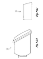
- Fig. 6 illustrates a headlamp yielded by the present invention having a ballast incorporated within its packaging.
- Fig. 7 consists of Figs. 7(a) and 7(b) respectively illustrating a conventional halogen headlamp and the xenon-metal halide headlamp related to the present invention.
- Fig. 8 consists of Figs. 8(a) and 8(b) respectively illustrating a dual beam conventional headlamp and a dual beam headlamp related to the present invention.
- the practice of the present invention is particularly (but not exclusively) suited to a xenon-metal halide lamp serving as a light source for automotive vehicle applications.
- the xenon-metal halide light source having a relatively long anticipated life of about 5000 hours not only provides for instant light to serve the illumination needs of the automobile, but also because of its reduced dimensions, relative to incandescent light sources, allows for a reduction in the hood lines of automobiles, thereby accommodating the aerodynamically styling desires of automotive designers.
- a presently preferred implementation of the present invention provides a circuit arrangement and a method for operating xenon-metal halide lamps yielding similar benefits as the operation of the circuit and method described in the previously mentioned U.S. Patent Application Serial No. 320,736.
- the presently preferred implementation operates the xenon-metal halide lamp having a xenon fill pressure of about 7 atmospheres, so as to yield an instant light output of at least 15000 lumens which amount is particularly suited for and more than meets the needs of automotive or vehicle lighting applications.
- the xenon-metal halide lamp operation results in a related hot-spot temperature below a critical value of 1000°C and has a wall loading of approximately 20 watts per square centimeter yielding an efficacy of about 70 lumens per watt (LPW).
- the xenon-metal halide lamp suited to the present implementation comprises an envelope having a bulbous portion with a volume between about 0.05 to about 1.0 cubic centimeters.
- the lamp may have a fill within its bulbous portion comprising a xenon gas having a cold pressure in the range of about 2 to about 15 atmospheres, mercury having an operating pressure in the range of about 2 to about 20 atmospheres and a metal halide compound of an amount in the range of about 1 to about 5 milligrams.
- the envelope forming the lamp lodges a pair of electrodes respectively located at opposite ends and which are spaced apart from each other by a distance from about 1.5 to about 5mm with the preferred amount being from about 2.0 to about 4.0mm.
- a preferred method in accordance with the invention of operating a high pressure xenon-metal halide lamp comprises applying a direct current (DC) excitation having various levels with each level having selectable amplitude of ripple and a selectable frequency of ripple imposed thereon.
- the ripple may further be frequency modulated.
- the DC excitation is an electric current flowing in one direction only and is substantially constant in value.
- the run circuit takes effect after the xenon-metal halide lamp has been energized or started by means of a starting pulse having an amplitude from about 10 kilovolts to about 20 kilovolts and a duration of about 0.1 microsecond.
- the starting pulse and the run current are sequentially applied to the electrodes of the xenon-metal halide lamp.
- the run current has a ripple imposed thereon which is preferably modulated in the range of about ⁇ 5% to about ⁇ 20% of the center frequency of the ripple signal which is preferably about 100kHz.
- the lamp is preferably operated with a warm-up current which is in the range from about 2 to 20 times the operating or run current to be described hereinafter with regard to Fig.2. The presently preferred method in accordance with the present invention is further described with reference to Fig.1.
- Fig. 1 illustrates DC acoustic operation 10 of xenon-metal halide lamps using high-frequency ripple.
- Fig. 1 has an X coordinate, given in kilohertz, in the range of 50 to 160 and is representative of a frequency of the ripple signal imposed on the second DC level or run signal that is applied to the high pressure xenon-metal halide lamp.
- the DC acoustic operation 10 is representative of the frequencies of the ripple signals for which the arc of the xenon-metal halide lamp is stable.
- the frequencies not encompassed are representative of the frequencies for which the arc operates in an unstable manner.
- the stable operation includes the effect of utilizing frequency modulation in the present method.
- the DC acoustic operation 10 of the present method is different than the AC acoustic operation described in U.S. Patent Application Serial No. 320,736 in that the waveform of the current of the present method that is applied to the xenon-metal halide lamp does not change signs or polarities so that there is no inherent modulation of the lamp power such as that accomplished by the circuit and method of U.S. Patent Application Serial No. 320,736.
- the DC acoustic operation 10 of the present method is somewhat similar to one aspect of U.S. Patent Application Serial No. 320,736 in that the frequency of the ripple applied to the run signal is approximately twice the frequency of the modulation disclosed in Serial No. 320,736 that provides acoustical straightening of the arc of the high pressure xenon-metal halide lamp.
- the arc straightening is primarily achieved due to the dominance of the acoustic motion of the xenon and mercury over the gravity-induced vertical convection of the xenon and mercury which otherwise would bend the arc between the electrodes in an upward manner.
- the frequency window of the stable, straightened arc in the operation 10 corresponds to the presence of acoustic perturbations of the gas which symmetrically force the arc to the center of the arc tube, rather than asymmetrically toward the wall of the arc tube.
- Fig. 2 has an X coordinate (time), given in seconds, related to the phases of operation of the xenon-metal halide lamp, and a Y coordinate (current), given in amperes, which is applied across the electrodes of the xenon-metal halide lamp.
- the phases of operation illustrated in Fig. 2 consist of; (1) a start phase related to signal 12 and ripple signal 16 and (2) a run phase related to signal 14 and a ripple signal 16.
- the ripple level of the signal 16 is selected in accordance with the following expression:
- ripple levels for signal 16 are needed to provide significantly wide frequency band for straight and stable operation of the arc, for example, ⁇ 25% of the operating frequency. Further still, proper frequency modulation is desired along with the ripple to produce the wide stable operating bands along the lines described in the aforementioned U.S. Patent Application Serial No. 320,736.
- the absolute ripple current level is roughly constant for both the starting voltage and run current, however the percentage ripple increases from warm-up to run. It should be recognized that other embodiments could be provided to impose various ripple levels separately on the start and run functions.
- a lamp current of about 3 amperes is initially applied to the xenon-metal halide lamp primarily to ionize the xenon gas and provide instant light for the vehicle.
- This relatively high current in and of itself, is capable of somewhat straightening the arc condition thereby reducing the need of advantageously imposing the ripple on the starting signal.
- This reduction in ripple correspondingly reduces the flicker in the headlamp employing the xenon-metal halide lamp that may typically be involved during warm-up at higher ripple levels or with AC operation.
- the reduced ripple level during warm-up is advantageous because the acoustic resonance frequencies and the stable operation windows are shifting as the gas temperature warms up, and any applied frequency is necessarily destabilizing at some time during the warm-up.
- the ripple level is kept low enough in this embodiment to avoid unfavorable acoustic resonances during warm-up.
- a further benefit related to the presently preferred method of the invention is to take advantage of the cataphoresis effects of the DC operation of the xenon-metal halide lamp.
- the effect of cataphoresis drives the positive ions, associated with the discharge condition between the electrodes, to the cathode resulting in severe axial color separation and reduced efficacy due to removal of radiating metal atoms (e.g. sodium and scandium) from the arc.
- the xenon-metal halide lamp having a relatively short arc gap or spacing between electrodes of 2mm and energized by the hereinbefore described DC acoustic operation does not manifest this severe separation problem.
- the metal halides within the fill are not completely separated out by the action of the DC cataphoresis so that even though there is some asymmetry in the axial distribution of the metal halides, the efficacy and desired color emission of the metal halide of the xenon-metal halide lamp are largely preserved and the lamp yield a homogeneous light.
- the beam produced by the automotive headlamp is created by superposition of images related to the arc of the light source wherein half of which are reversed or mirror images of the other, the weak axial asymmetries remaining in the arc are cancelled out by the beam pattern.
- This occurrence is created, in part, by optics of the headlamp, for example, the reflector of the headlamp functioning to blend or merge all of the images of the light source into one beam pattern that is projected by the headlamp onto the road.
- the xenon-metal halide lamp may be operated with a slight cataphoresis effect so that color separation occurs wherein the light associated with a cool plume configuration located above the arc differs in color from the remaining white arc of the lamp.
- the colored plume appears as colored illuminator in the center foreground of the road in front of the car.
- FIG. 3, 4 and 5 A preferred embodiment of the present invention is schematically illustrated in Figs. 3, 4 and 5 for an operating circuit related to first and second xenon-metal halide lamps respectively which provide the light source for the high and low beam illuminations of a vehicle.
- the embodiment of Figs. 3, 4 and 5 are composed of various components of a typical value or of a type as designated in Table 1.
- the circuit arrangement shown in Figs. 3, 4 and 5 generates the starting voltage and run current along with the ripple signal all previously discussed with regard to Figs. 1 and 2 so as to start and operate the xenon-metal halide lamps in a manner as disclosed hereinbefore.
- the circuit arrangement further provides for the means for developing the run signal of a DC direct current level having a relatively low value and which has imposed thereto the ripple signal having a range of selectable amplitudes and a range of selectable frequencies.
- the circuit arrangement further comprises means for generating the start signal having the ripple imposed thereon.
- the values of this starting voltage and run current along with respective ripple signals have been given hereinbefore.
- the starting voltage of about 20KV having a duration of about 0.1 microseconds is applied across the xenon-metal halide lamp for a predetermined duration so as to cause the ionization of the ingredients in the lamp and thus the starting thereof.
- the ballast circuit of Figs. 3, 4 and 5 consists essentially of three separate dc-to-dc power converters: one to run and two for starting the individual (high and low beam) light sources.
- the ballast circuit operates to generate the start and run signals previously discussed with regard to Fig. 2 that provide instant light for each of the xenon-metal halide lamps shown in Fig. 3 as low beam and high beam.
- the initiation for activation of the low and high beam light sources is via a control signal (HIGH or LOW) from an external device such as that typically found in automobiles.
- the basic circuit topology for each of the three converters is that of the well-known boost converter.
- the use of separate starters for both the high and low beam light sources eliminates the need for high voltage switching while enabling the use of a single run converter for both of the light sources.
- the start converter delivers a 20kv pulse superimposed on the output of the run converter.
- the run converter is active at all times following the application of battery power at either the "HIGH” or "LOW" input terminals shown at the input stage of Fig. 3. Application of power to either of these terminals also activates the associated starter by means of relay K1, its contact K 1C , and inductor L1. As will be discussed hereinafter, the associated starter is shut down as soon as lamp current is established.
- the run converter is a tapped inductor boost converter comprising power switching transistor, Q1; inductor, L2; diode, D21; capacitors, C9 and C10; and the pulse width modulator (PWM) controller, U7.
- the run current primarily controlled by Q1 having its bias controlled by pulse width modulator U7, is applied to the lamps (high beam and low beam) via the path formed by D21 and T1B and T2B.
- the transformer winding T1B and T2B are essential to the start circuits to be discussed and form part of the run circuit. The inductance of these windings are desired to be small enough to allow rapid current build-up in the lamps and large enough to effectively couple the start pulse into the lamps.
- the run converter is controlled, in part, by lamp current which is sampled by shunt resistor, R23 and fed back to the controller (U7 pin2) after being smoothed by the low pass filter, R38, R39, and C25.
- the average current applied to the lamp is controlled in a high gain closed loop.
- the reference for this loop is modified by the lamp voltage such that the lamp current decreases linearly with increasing lamp voltage provided this lamp voltage is within a predefined operating band or window to be described. In this manner, the lamp power (voltage times current) remains substantially constant with normal lamp voltage variations as well as with normal input voltage (D.C. battery) variations. If lamp voltage is outside the predetermined window, the reference for the high gain closed loop changes to produce a desired constant lamp current. Normally the reference remains constant except for a predefined warm-up time to be described.
- the circuit that establishes the predetermined window is shown in Fig. 4 and comprises a pair of precision voltage clamps consisting of diodes, D13, D14 and the associated op-amps U8C and U8D (which are part of the quad amplifier, U8).
- Lamp voltage of either low or high beam applied to the top or input to the series resistor string, R40, R41, R42, R43, via R23 and C11, results in a current through the string which is part of the high gain control loop reference used for the operation of the pulse width modulation U7 (pin2). This current is proportional to lamp voltage provided neither of the two precision clamps is active.
- the clamps are designed to activate at the upper and lower lamp operating voltage limits such as 40 to 50 volts.
- the reference for the control loop is independent of lamp voltage and provided by U8A or U8B. During this condition the lamp current is therefore held constant provided the warm-up timers have timed-out.
- the high beam timer consists of transistors, Q5 and Q6 along with an op-amp U8B that is a part of integrated circuit, U8.
- the low beam timer includes Q7, Q8 and an op-amp U8C which is also part of U8.
- the purpose of the warm-up timers is to supply much higher than normal power to warm up the lamp quickly then taper off to the desired run power.
- the timer includes an important memory feature. When power, in the form of the run signal, is removed and reapplied to either of the light sources, the timer remembers how long its associated light source was off and adjusts the subsequent warm-up time accordingly. Without this feature, a consistent warm-up program of power control would be imposed on the lamp resulting in possible damage to the xenon-metal halide lamps from frequent short power interruptions.
- the timer imparts a certain desirable dwell at the beginning of the time cycle of the current applied to the lamp.
- Lamp power is held at maximum during the dwell time.
- the dwell is caused by the initial voltage at the inverting input of the op-amp U8C. This initial voltage holds the op-amp U8C in saturation (low output) until the timing capacitor has charged up to match the initial voltage.
- the timing capacitor discharges through R50 and R51. If power to the lamp is reapplied before the capacitor completely discharges, the circuit will time-out faster than it would if the capacitor were allowed to fully discharge.
- the time during which high power is imposed on the lamp by the circuit depends on the amount of time that power is off. Shorter off-times result in shorter intervals of high power.
- the timer circuit design includes these above features so that circuit time constants are roughly matched to the thermal time constants of the lamp. The result is substantially constant light from the moment the switch is thrown from an external source to energize the xenon-metal halide lamp which yields instant light.
- the high beam starter primarily includes integrated circuit, U5; transistor, Q3; inductor, L4; diode, D23; capacitors, C15 and C16; transformer, T2; and associated bias components.
- the low beam starter has identical components arranged around integrated circuit, U4 as shown in Fig. 5. In that both starters are identical only the operation of the high beam starter is to be described.
- the starter is an independent boost converter operating with current feedback only. Assuming that the starter is enabled, inductor, L4 injects pulses of current into capacitors, C15 and C16. The capacitors accumulate enough charge until their voltage rises to the breakdown potential of the spark gap SG1. The spark gap discharges the charge of the capacitors into the primary T2A of transformer, T2 and the transformer couples the resulting energy pulse into the lamp via the secondary winding T2B. This circuit action continues until the starter is automatically disabled after the lamp has started as to be described.
- Comparator, U6B of Fig. 3 provides the enable/disable input to the related starter. This comparator senses the average lamp voltage via its + input and, when this voltage falls below a certain value for example 184V, the starter is disabled via path D8 of Fig. 5. In a manner similar to that of U6B, comparator U6C of Fig. 3 provides a voltage limit function for the run converter. This comparator monitors the output voltage of the run converter via its + input and R29 and, when the voltage exceeds a certain value e.g., 200v, outputs an inhibit command to the run converter via pin 3 of U7.
- a certain value e.g. 200v
- Comparator, U6D provides for an anti drop-out feature for the xenon-metal halide lamp.
- This comparator senses lamp voltage changes (not the voltage itself, but changes in the voltage). In the event of a sudden rise in lamp voltage, the comparator outputs a command to U7 via pin 2, which, in turn, is applied to pin 1 of U7 via R36 and C21 so as to increase the lamp current for a short time.
- a sudden increase in lamp voltage may be due to an undesired mechanical shock and this design feature of U6D advantageously keeps the lamp lit.
- Comparator, U6A provides for automatic shut-down of the ballast in the event of a failed lamp.
- Timing components, C17 and R24 determine the maximum amount of time, for example, 0.5 seconds that either starter can operate before shutdown of ballast circuit of Figs. 3, 4 and 5 may occur.
- the starters are inactivated via the path formed by D10, R24, and D7 and D8, whereas, the run circuit is inactivated via the path formed by D11, and pin 3 of U7. This feature reduces the probability of radio interference due to inoperative starting of the lamps.
- a timer IC (U3) provided for a flash-to-pass feature related to'the present invention.
- This IC is configured as a free-running oscillator with a period of 0.5 second.
- the oscillator is enabled.
- the oscillator causes the lamp current to pulse to a higher value every half second via path D6, C20, U6D, R36, C21 and pin 1 of U7.
- a minimum off-time feature related to the present invention is provided by integrated circuit, U1A (a timer configured as a one-shot). Anytime the input power, via the terminals LOW, HIGH of Fig. 3, is removed then quickly reapplied, U1A holds-off the operation of the run converter via the path formed by D3, R5 and pin 3 of U7, for 20 milliseconds. Without this feature, a rapid switch between the high and low lamps could result in the original lamp remaining on.
- Integrated circuit, U1B (configured as an astable mv) provides for frequency modulation of the lamp current.
- the sawtooth output (signal 18 of Fig. 3) from this circuit feeds into the frequency determining input (pin 4) of the run converter's PWM controller U7 via the path formed by R4 and C3.
- the modulation frequency (the output frequency from U1B) is about 500Hz.
- the run current has (1) a frequency modulation of about 500Hz, (2) a ripple frequency of about 100kHz and (3) a ripple amplitude of about 50%. These quantities may be varied, adjusted or selected by (1) selecting the frequency modulation of U1B, (2) selecting a lower value of C9, such as, to increase the amplitude of ripple to a value of 60%, and (3) C10 so as to alter the frequency of the ripple signal.
- the DC ballast circuit disclosed with regard to Figs. 3, 4 and 5 along with a reflector and the illustrative xenon-metal halide light source useful with the present invention may be arranged into a single package and housed in a space that is smaller than that presently provided for conventional automotive headlamps.
- a DC ballast circuit mounted to the rear of dual headlamp reflectors is illustrated in one embodiment in Fig. 6.
- Fig. 6 illustrates a dual headlamp 30 having a first reflector 32 along with a xenon-metal halide lamp 34 related to a high beam illumination and a second reflector 36 along with a xenon-metal halide lamp 38 related to the lower beam illumination.
- the headlamp 30 has contained within its housing the ballast circuit 20 described with regard to Figs. 3, 4 and 5.
- the ballast circuit is mounted on a circuit board 40 which occupies some of the area in the back of the high and low beam reflectors 32 and 36.
- the integrated automotive headlamp has a height 42 of about 50mm, a width 44 of about 250mm, and a depth 40 of about 100mm.
- the present headlamp represents a reduction in the overall dimensions relative a typical halogen headlamp 50 that provides both the high beam and low beam illumination and may be discussed with regard to Fig. 7 which is composed of Figs. 7A and 7B respectively illustrating the conventional headlamp 50 and the headlamp 30 previously discussed with regard to Fig. 6.
- the headlamp 30 in accordance with the present invention relative to the conventional halogen headlamp 50 provides for an overall volume reduction of about 75%.
- Fig. 8 is composed of Figs. 8A and 8B respectively illustrating the dual headlamp 60 having a halogen light source and the headlamp 30 of the present invention discussed with regard to Figs. 6 and 7B.
- Fig. 8A to 8B A comparison from Fig. 8A to 8B reveals that the headlamp 30 provides for a substantial reduction in the overall dimensions by at least a factor of 75%.
- the illustrative practice of the present invention allows for a substantial reduction in the overall dimensions of the headlamp employing a xenon-metal halide light source and having a DC acoustic operation.
- DC acoustic operation allows for a high pressure xenon-metal halide lamp to have a straighten arc and to be horizontally oriented while also being provided with instant light which is especially suited for automotive applications.
- the illustrative practice of the present invention allows for the DC operation of a xenon-metal halide lamp having a short arc gap that provides high efficiency and good color emissions.
- This short arc gap also provides for the utilization of weak cataphoresis effects which yields a desired beam pattern less annoying to an oncoming vehicle.
- a single metal halide lamp may be used to provide both high and low beam illumination along the lines as described in U.S. Patent Application Serial No. 320,736.
- the previous description was related to a single ripple signal imposed on both the run signal and the start signal, it should be recognized that means may be provided to have separate ripple signals for the run and start signals. Further, if desired, the start signal may be provided that is devoid of any ripple signal and of any frequency modulation.
Abstract
Description
- This invention relates to a method and an operating circuit both for gas discharge light sources, e.g. xenon-metal halide lamps.
- U.S. Patent Application Serial No. 157,436 filed February 18, 1988 of R. S. Bergman et al, (GB-A-2216334) (L-9844) and herein incorporated by reference, discloses a xenon-metal halide lamp particularly suited for automotive applications. The xenon-metal halide lamp provides improved efficiency and longer life relative to incandescent lamps while a high pressure of xenon gas primarily achieves instant light capabilities making such a lamp particularly suited for automotive applications.
- U.S. Patent Application 320,736 filed March 8, 1989 of G.R. Allen et al, (EP-A-0386990) (L-9950) and herein incorporated by reference, discloses an AC ballast circuit for acoustically operating xenon-metal halide lamps to provide a straight arc condition between the electrodes of the xenon-metal halide lamp. The straight arc provides for a point-like source that is beneficial for optical purposes and also prevents the arc from touching the walls of the lamp so as not to reduce the life of the lamp. Further, in a preferred embodiment, frequency modulation is incorporated to broaden the desired operational frequency bands that provide for the straight arc.
- Although the AC ballast circuit and method of operating of Serial No. 320,736 serves well the needs of the xenon-metal halide lamp, it is desired that the circuit complexity be reduced in order to correspondingly reduce the cost and size of the ballast circuit so as to allow the ballast circuit to be more easily integrated into the automotive housing. A reduction could be provided by allowing the ballast circuit to be directly connected to the DC source of excitation (battery) of the automobile and thereby eliminate the associated circuit components of the DC/AC converter.
- As discussed in US-A-4935668 (US Application Serial No. 157,360 of R. L. Hansler et al) assigned to the same assignee as the present invention and herein incorporated by reference, lamps having a metal halide ingredient, that are operated from a DC source of excitation typically experience the effects of cataphoresis which cause the halides of a metal halide lamp to be moved or swept into the end regions of the lamp so as not to contribute to providing the desired illumination of such a lamp. This cataphoresis effect is particularly noticed when the light source is horizontally arranged such as in automotive applications. It is desired that means be provided to allow for xenon-metal halide lamps to be operated from a DC source without suffering the accompanying disadvantageous effects of cataphoresis typically encountered for such DC lamp operation. In addition, it is desired that such DC operation provide for a straighten arc between the electrodes of the xenon-metal halide lamp.
- Embodiments of the present invention as disclosed herein seek to provide: a circuit connected to a DC source for operation of a xenon-metal halide lamp; a method of operating a xenon-metal halide lamp in a DC manner without the disadvantageous effects of cataphoresis while at the same time providing a straight arc between the electrodes of the xenon-metal halide lamp; a DC circuit that allows for an overall reduction in size relative to AC ballast type circuits employed for xenon-metal halide lamps; and/or improvements that enhance the illumination patterns yielded by xenon-metal halide lamps and made available for automotive applications.
- An embodiment of the present invention is directed to a circuit and a method for DC operation of a high pressure xenon-metal halide lamp which are particularly suited for automotive applications.
- The operating circuit comprises means for developing a first signal or pulse having a relatively high amplitude and a relatively short duration. The high voltage pulse signal acts as a signal for starting the lamps. The operating circuit further comprises means for developing and applying to the xenon-metal halide lamp a first signal or direct current level having a relatively low value, means for developing a first ripple signal having a first range of selectable amplitudes and a first range of selectable frequencies, and means for combining the first DC level signal and the first ripple signal into a run or operate signal. The operating circuit further preferably comprises means for monitoring and terminating the voltage across the xenon-metal halide lamp if such reaches or falls below predetermined values selected for the run or start signals respectively.
- The method comprises selecting the amplitude and frequency of the run signal such that the xenon-metal halide lamp is acoustically operated so as to provide a straightened arc between its electrodes. The method further comprises frequency modulating the signal applied to the lamp by a selectable amount so as to further increase the frequency range for acoustically operating the lamp. Still further, the method comprises the selection of the parameters of the run signal so that the xenon-metal halide lamp is provided with a weak cataphoresis effect that yields a separated colored light for vehicle illumination patterns that is non-offensive to a viewer inside the vehicle.
- Reference will now be made by way of example to the accompanying drawings, in which:
- Fig. 1 is an illustration of the frequency bands related to the DC acoustic operation of xenon-metal halide lamps using high-frequency ripple.
- Fig. 2 illustrates the DC levels having various ripple signals imposed thereon during phases of operation of the xenon-metal halide lamp related to the present invention.
- Fig. 3 is a schematic primarily illustrating a run converter according to the present invention.
- Fig. 4 is a schematic of the high and low warm-up timers related to the present invention.
- Fig. 5 is a schematic of the high and low starter circuits for operating the high pressure xenon-metal halide lamp.
- Fig. 6 illustrates a headlamp yielded by the present invention having a ballast incorporated within its packaging.
- Fig. 7 consists of Figs. 7(a) and 7(b) respectively illustrating a conventional halogen headlamp and the xenon-metal halide headlamp related to the present invention.
- Fig. 8 consists of Figs. 8(a) and 8(b) respectively illustrating a dual beam conventional headlamp and a dual beam headlamp related to the present invention.
- The practice of the present invention is particularly (but not exclusively) suited to a xenon-metal halide lamp serving as a light source for automotive vehicle applications. As described in the previously mentioned U.S. Patent Application Serial No. 157,436, the xenon-metal halide light source having a relatively long anticipated life of about 5000 hours not only provides for instant light to serve the illumination needs of the automobile, but also because of its reduced dimensions, relative to incandescent light sources, allows for a reduction in the hood lines of automobiles, thereby accommodating the aerodynamically styling desires of automotive designers.
- A presently preferred implementation of the present invention provides a circuit arrangement and a method for operating xenon-metal halide lamps yielding similar benefits as the operation of the circuit and method described in the previously mentioned U.S. Patent Application Serial No. 320,736. The presently preferred implementation operates the xenon-metal halide lamp having a xenon fill pressure of about 7 atmospheres, so as to yield an instant light output of at least 15000 lumens which amount is particularly suited for and more than meets the needs of automotive or vehicle lighting applications. The xenon-metal halide lamp operation results in a related hot-spot temperature below a critical value of 1000°C and has a wall loading of approximately 20 watts per square centimeter yielding an efficacy of about 70 lumens per watt (LPW).
- The xenon-metal halide lamp suited to the present implementation comprises an envelope having a bulbous portion with a volume between about 0.05 to about 1.0 cubic centimeters. The lamp may have a fill within its bulbous portion comprising a xenon gas having a cold pressure in the range of about 2 to about 15 atmospheres, mercury having an operating pressure in the range of about 2 to about 20 atmospheres and a metal halide compound of an amount in the range of about 1 to about 5 milligrams. Further, the envelope forming the lamp lodges a pair of electrodes respectively located at opposite ends and which are spaced apart from each other by a distance from about 1.5 to about 5mm with the preferred amount being from about 2.0 to about 4.0mm.
- A preferred method in accordance with the invention of operating a high pressure xenon-metal halide lamp comprises applying a direct current (DC) excitation having various levels with each level having selectable amplitude of ripple and a selectable frequency of ripple imposed thereon. The ripple may further be frequency modulated. The DC excitation is an electric current flowing in one direction only and is substantially constant in value. The run circuit takes effect after the xenon-metal halide lamp has been energized or started by means of a starting pulse having an amplitude from about 10 kilovolts to about 20 kilovolts and a duration of about 0.1 microsecond. The starting pulse and the run current are sequentially applied to the electrodes of the xenon-metal halide lamp. The run current has a ripple imposed thereon which is preferably modulated in the range of about ± 5% to about ± 20% of the center frequency of the ripple signal which is preferably about 100kHz. The lamp is preferably operated with a warm-up current which is in the range from about 2 to 20 times the operating or run current to be described hereinafter with regard to Fig.2. The presently preferred method in accordance with the present invention is further described with reference to Fig.1.
- Fig. 1 illustrates DC
acoustic operation 10 of xenon-metal halide lamps using high-frequency ripple. Fig. 1 has an X coordinate, given in kilohertz, in the range of 50 to 160 and is representative of a frequency of the ripple signal imposed on the second DC level or run signal that is applied to the high pressure xenon-metal halide lamp. The DCacoustic operation 10 is representative of the frequencies of the ripple signals for which the arc of the xenon-metal halide lamp is stable. The frequencies not encompassed are representative of the frequencies for which the arc operates in an unstable manner. The stable operation includes the effect of utilizing frequency modulation in the present method. - The DC
acoustic operation 10 of the present method is different than the AC acoustic operation described in U.S. Patent Application Serial No. 320,736 in that the waveform of the current of the present method that is applied to the xenon-metal halide lamp does not change signs or polarities so that there is no inherent modulation of the lamp power such as that accomplished by the circuit and method of U.S. Patent Application Serial No. 320,736. The DCacoustic operation 10 of the present method is somewhat similar to one aspect of U.S. Patent Application Serial No. 320,736 in that the frequency of the ripple applied to the run signal is approximately twice the frequency of the modulation disclosed in Serial No. 320,736 that provides acoustical straightening of the arc of the high pressure xenon-metal halide lamp. - In a manner similar to that described in Serial No. 320,736, we have discovered that the DC
acoustic operation 10, of the xenon-metal halide lamp significantly reduces the gravity-induced convection ordinarily encountered with such xenon-metal halide lamps having a xenon fill pressure in excess of two (2) atmospheres. The effect of the operation shown in Fig. 1 is to acoustically operate the xenon-metal halide lamp in such a manner that the upper wall temperatures of the related lamps are reduced by about 200°C relative to non-acoustic operation, while at the same time the gravity-induced convection of the arc toward the electrodes is substantially reduced even to the point of arc straightening conditions. The arc straightening is primarily achieved due to the dominance of the acoustic motion of the xenon and mercury over the gravity-induced vertical convection of the xenon and mercury which otherwise would bend the arc between the electrodes in an upward manner. The frequency window of the stable, straightened arc in theoperation 10 corresponds to the presence of acoustic perturbations of the gas which symmetrically force the arc to the center of the arc tube, rather than asymmetrically toward the wall of the arc tube. - In addition to providing the straight arc of the xenon-metal halide lamp, the DC
acoustic operation 10 reduces the amount of flicker during warm-up and broadens the frequency window for straight and stable operation relative to AC acoustic operation to provide a stable headlamp illumination pattern. Such a reduction may be described with reference to Fig. 2 which illustrates a current waveform of current 12 consisting ofsegments 
- For the run phase of operation of the xenon-metal halide lamp corresponding to signal 14, we have found that ripple levels for signal 16 of at least 30% and preferably 60% are needed to provide significantly wide frequency band for straight and stable operation of the arc, for example, ± 25% of the operating frequency. Further still, proper frequency modulation is desired along with the ripple to produce the wide stable operating bands along the lines described in the aforementioned U.S. Patent Application Serial No. 320,736. For the circuit arrangement embodiment shown in Figs. 3, 4, and 5, to be described hereinafter, the absolute ripple current level is roughly constant for both the starting voltage and run current, however the percentage ripple increases from warm-up to run. It should be recognized that other embodiments could be provided to impose various ripple levels separately on the start and run functions.
- During the start phase, a lamp current of about 3 amperes is initially applied to the xenon-metal halide lamp primarily to ionize the xenon gas and provide instant light for the vehicle. This relatively high current, in and of itself, is capable of somewhat straightening the arc condition thereby reducing the need of advantageously imposing the ripple on the starting signal. This reduction in ripple correspondingly reduces the flicker in the headlamp employing the xenon-metal halide lamp that may typically be involved during warm-up at higher ripple levels or with AC operation. The reduced ripple level during warm-up is advantageous because the acoustic resonance frequencies and the stable operation windows are shifting as the gas temperature warms up, and any applied frequency is necessarily destabilizing at some time during the warm-up. The ripple level is kept low enough in this embodiment to avoid unfavorable acoustic resonances during warm-up.
- A further benefit related to the presently preferred method of the invention is to take advantage of the cataphoresis effects of the DC operation of the xenon-metal halide lamp. Normally in DC operation, the effect of cataphoresis drives the positive ions, associated with the discharge condition between the electrodes, to the cathode resulting in severe axial color separation and reduced efficacy due to removal of radiating metal atoms (e.g. sodium and scandium) from the arc. However, we have discovered that in the practice of the present method, the xenon-metal halide lamp having a relatively short arc gap or spacing between electrodes of 2mm and energized by the hereinbefore described DC acoustic operation does not manifest this severe separation problem. For such lamps, the metal halides within the fill are not completely separated out by the action of the DC cataphoresis so that even though there is some asymmetry in the axial distribution of the metal halides, the efficacy and desired color emission of the metal halide of the xenon-metal halide lamp are largely preserved and the lamp yield a homogeneous light.
- Furthermore, we have discovered that in automotive applications, where the beam produced by the automotive headlamp is created by superposition of images related to the arc of the light source wherein half of which are reversed or mirror images of the other, the weak axial asymmetries remaining in the arc are cancelled out by the beam pattern. This occurrence is created, in part, by optics of the headlamp, for example, the reflector of the headlamp functioning to blend or merge all of the images of the light source into one beam pattern that is projected by the headlamp onto the road.
- Still further, we have discovered that weak cataphoresis related to the present method of the invention has a further beneficial effect in the headlamp applications. The xenon-metal halide lamp may be operated with a slight cataphoresis effect so that color separation occurs wherein the light associated with a cool plume configuration located above the arc differs in color from the remaining white arc of the lamp. We have discovered, when such a color-separated arc condition is projected onto the road as a beam pattern, the colored plume appears as colored illuminator in the center foreground of the road in front of the car. In the present method of the invention DC acoustic operation of the xenon-metal halide having the capability of weak cataphoresis, this colored light is less intense and appears to be off to the side of the road where it is less noticeable rather than concentrated on the center of the road. Such a beam illumination is less offensive to a viewer inside the vehicle.
- A preferred embodiment of the present invention is schematically illustrated in Figs. 3, 4 and 5 for an operating circuit related to first and second xenon-metal halide lamps respectively which provide the light source for the high and low beam illuminations of a vehicle. The embodiment of Figs. 3, 4 and 5 are composed of various components of a typical value or of a type as designated in Table 1.


- In general, the circuit arrangement shown in Figs. 3, 4 and 5 generates the starting voltage and run current along with the ripple signal all previously discussed with regard to Figs. 1 and 2 so as to start and operate the xenon-metal halide lamps in a manner as disclosed hereinbefore. The circuit arrangement further provides for the means for developing the run signal of a DC direct current level having a relatively low value and which has imposed thereto the ripple signal having a range of selectable amplitudes and a range of selectable frequencies. The circuit arrangement further comprises means for generating the start signal having the ripple imposed thereon. The values of this starting voltage and run current along with respective ripple signals have been given hereinbefore. The starting voltage of about 20KV having a duration of about 0.1 microseconds is applied across the xenon-metal halide lamp for a predetermined duration so as to cause the ionization of the ingredients in the lamp and thus the starting thereof.
- The ballast circuit of Figs. 3, 4 and 5 consists essentially of three separate dc-to-dc power converters: one to run and two for starting the individual (high and low beam) light sources. The ballast circuit operates to generate the start and run signals previously discussed with regard to Fig. 2 that provide instant light for each of the xenon-metal halide lamps shown in Fig. 3 as low beam and high beam. The initiation for activation of the low and high beam light sources is via a control signal (HIGH or LOW) from an external device such as that typically found in automobiles. The basic circuit topology for each of the three converters is that of the well-known boost converter. The use of separate starters for both the high and low beam light sources eliminates the need for high voltage switching while enabling the use of a single run converter for both of the light sources. The start converter delivers a 20kv pulse superimposed on the output of the run converter. The run converter is active at all times following the application of battery power at either the "HIGH" or "LOW" input terminals shown at the input stage of Fig. 3. Application of power to either of these terminals also activates the associated starter by means of relay K₁, its contact K1C, and inductor L1. As will be discussed hereinafter, the associated starter is shut down as soon as lamp current is established.
- The run converter is a tapped inductor boost converter comprising power switching transistor, Q1; inductor, L2; diode, D21; capacitors, C9 and C10; and the pulse width modulator (PWM) controller, U7. The run current, primarily controlled by Q1 having its bias controlled by pulse width modulator U7, is applied to the lamps (high beam and low beam) via the path formed by D21 and T1B and T2B. The transformer winding T1B and T2B are essential to the start circuits to be discussed and form part of the run circuit. The inductance of these windings are desired to be small enough to allow rapid current build-up in the lamps and large enough to effectively couple the start pulse into the lamps. An inductance in the
range 30 to 100 microhenry is desired. The selection of a relatively small output capacitor of the run circuit (C10 of Fig. 3) results in a high output ripple, essential to acoustic straightening of the arc, to be applied to the run current of the xenon-metal halide lamp. - The run converter is controlled, in part, by lamp current which is sampled by shunt resistor, R23 and fed back to the controller (U7 pin2) after being smoothed by the low pass filter, R38, R39, and C25. The average current applied to the lamp is controlled in a high gain closed loop. The reference for this loop is modified by the lamp voltage such that the lamp current decreases linearly with increasing lamp voltage provided this lamp voltage is within a predefined operating band or window to be described. In this manner, the lamp power (voltage times current) remains substantially constant with normal lamp voltage variations as well as with normal input voltage (D.C. battery) variations. If lamp voltage is outside the predetermined window, the reference for the high gain closed loop changes to produce a desired constant lamp current. Normally the reference remains constant except for a predefined warm-up time to be described.
- The circuit that establishes the predetermined window is shown in Fig. 4 and comprises a pair of precision voltage clamps consisting of diodes, D13, D14 and the associated op-amps U8C and U8D (which are part of the quad amplifier, U8). Lamp voltage of either low or high beam, applied to the top or input to the series resistor string, R40, R41, R42, R43, via R23 and C11, results in a current through the string which is part of the high gain control loop reference used for the operation of the pulse width modulation U7 (pin2). This current is proportional to lamp voltage provided neither of the two precision clamps is active. The clamps are designed to activate at the upper and lower lamp operating voltage limits such as 40 to 50 volts. When lamp voltage is outside the limits established by these clamps, the reference for the control loop is independent of lamp voltage and provided by U8A or U8B. During this condition the lamp current is therefore held constant provided the warm-up timers have timed-out. There are two timers which are identical, one for the high beam and one for the low beam. The high beam timer consists of transistors, Q5 and Q6 along with an op-amp U8B that is a part of integrated circuit, U8. the low beam timer includes Q7, Q8 and an op-amp U8C which is also part of U8.
- The purpose of the warm-up timers is to supply much higher than normal power to warm up the lamp quickly then taper off to the desired run power. The timer includes an important memory feature. When power, in the form of the run signal, is removed and reapplied to either of the light sources, the timer remembers how long its associated light source was off and adjusts the subsequent warm-up time accordingly. Without this feature, a consistent warm-up program of power control would be imposed on the lamp resulting in possible damage to the xenon-metal halide lamps from frequent short power interruptions.
- In that both the warm-up timers are similar, the operation of high beam timer is only to be described. The application of battery power to the "HIGH" input terminal renders conductive or turns-on and saturates transistors, Q5 and Q6. Timing capacitor, C27 charges through R50 and Q5 from the regulated 5 volt source connection to Q5. The capacitor's (27) voltage is buffered by op-amp U8C and appears at the top end of resistor, R56 via R48. The current in R56 forms part of the control loop reference and is fed back to
pin 2 of U7. The loop reference therefore changes with the voltage on the timing capacitor to produce a decreasing lamp current until the timing capacitor becomes fully charged. The timer imparts a certain desirable dwell at the beginning of the time cycle of the current applied to the lamp. Lamp power is held at maximum during the dwell time. The dwell is caused by the initial voltage at the inverting input of the op-amp U8C. This initial voltage holds the op-amp U8C in saturation (low output) until the timing capacitor has charged up to match the initial voltage. When power is removed from the lamp, the timing capacitor discharges through R50 and R51. If power to the lamp is reapplied before the capacitor completely discharges, the circuit will time-out faster than it would if the capacitor were allowed to fully discharge. The time during which high power is imposed on the lamp by the circuit depends on the amount of time that power is off. Shorter off-times result in shorter intervals of high power. The timer circuit design includes these above features so that circuit time constants are roughly matched to the thermal time constants of the lamp. The result is substantially constant light from the moment the switch is thrown from an external source to energize the xenon-metal halide lamp which yields instant light. - There are two starters both shown in Fig. 5: one for the high beam lamp and one for the low beam lamp. The high beam starter primarily includes integrated circuit, U5; transistor, Q3; inductor, L4; diode, D23; capacitors, C15 and C16; transformer, T2; and associated bias components. The low beam starter has identical components arranged around integrated circuit, U4 as shown in Fig. 5. In that both starters are identical only the operation of the high beam starter is to be described. The starter is an independent boost converter operating with current feedback only. Assuming that the starter is enabled, inductor, L4 injects pulses of current into capacitors, C15 and C16. The capacitors accumulate enough charge until their voltage rises to the breakdown potential of the spark gap SG1. The spark gap discharges the charge of the capacitors into the primary T2A of transformer, T2 and the transformer couples the resulting energy pulse into the lamp via the secondary winding T2B. This circuit action continues until the starter is automatically disabled after the lamp has started as to be described.
- Comparator, U6B of Fig. 3, provides the enable/disable input to the related starter. This comparator senses the average lamp voltage via its + input and, when this voltage falls below a certain value for example 184V, the starter is disabled via path D8 of Fig. 5. In a manner similar to that of U6B, comparator U6C of Fig. 3 provides a voltage limit function for the run converter. This comparator monitors the output voltage of the run converter via its + input and R29 and, when the voltage exceeds a certain value e.g., 200v, outputs an inhibit command to the run converter via
pin 3 of U7. - Comparator, U6D provides for an anti drop-out feature for the xenon-metal halide lamp. This comparator senses lamp voltage changes (not the voltage itself, but changes in the voltage). In the event of a sudden rise in lamp voltage, the comparator outputs a command to U7 via
pin 2, which, in turn, is applied to pin 1 of U7 via R36 and C21 so as to increase the lamp current for a short time. A sudden increase in lamp voltage may be due to an undesired mechanical shock and this design feature of U6D advantageously keeps the lamp lit. - Comparator, U6A provides for automatic shut-down of the ballast in the event of a failed lamp. Timing components, C17 and R24 determine the maximum amount of time, for example, 0.5 seconds that either starter can operate before shutdown of ballast circuit of Figs. 3, 4 and 5 may occur. The starters are inactivated via the path formed by D10, R24, and D7 and D8, whereas, the run circuit is inactivated via the path formed by D11, and
pin 3 of U7. This feature reduces the probability of radio interference due to inoperative starting of the lamps. - A timer IC (U3) provided for a flash-to-pass feature related to'the present invention. This IC is configured as a free-running oscillator with a period of 0.5 second. When both HIGH and LOW inputs are present (together) at the input stage of U2, the oscillator is enabled. The oscillator causes the lamp current to pulse to a higher value every half second via path D6, C20, U6D, R36, C21 and
pin 1 of U7. - A minimum off-time feature related to the present invention is provided by integrated circuit, U1A (a timer configured as a one-shot). Anytime the input power, via the terminals LOW, HIGH of Fig. 3, is removed then quickly reapplied, U1A holds-off the operation of the run converter via the path formed by D3, R5 and
pin 3 of U7, for 20 milliseconds. Without this feature, a rapid switch between the high and low lamps could result in the original lamp remaining on. - Integrated circuit, U1B (configured as an astable mv) provides for frequency modulation of the lamp current. The sawtooth output (signal 18 of Fig. 3) from this circuit feeds into the frequency determining input (pin 4) of the run converter's PWM controller U7 via the path formed by R4 and C3. The modulation frequency (the output frequency from U1B) is about 500Hz.
- For the embodiment shown in Figs. 3, 4 and 5, the run current has (1) a frequency modulation of about 500Hz, (2) a ripple frequency of about 100kHz and (3) a ripple amplitude of about 50%. These quantities may be varied, adjusted or selected by (1) selecting the frequency modulation of U1B, (2) selecting a lower value of C9, such as, to increase the amplitude of ripple to a value of 60%, and (3) C10 so as to alter the frequency of the ripple signal.
- The DC ballast circuit disclosed with regard to Figs. 3, 4 and 5 along with a reflector and the illustrative xenon-metal halide light source useful with the present invention may be arranged into a single package and housed in a space that is smaller than that presently provided for conventional automotive headlamps. In illustrative practice of the present invention, a DC ballast circuit mounted to the rear of dual headlamp reflectors is illustrated in one embodiment in Fig. 6.
- Fig. 6 illustrates a
dual headlamp 30 having afirst reflector 32 along with a xenon-metal halide lamp 34 related to a high beam illumination and asecond reflector 36 along with a xenon-metal halide lamp 38 related to the lower beam illumination. Theheadlamp 30 has contained within its housing theballast circuit 20 described with regard to Figs. 3, 4 and 5. The ballast circuit is mounted on a circuit board 40 which occupies some of the area in the back of the high andlow beam reflectors height 42 of about 50mm, awidth 44 of about 250mm, and a depth 40 of about 100mm. - The present headlamp represents a reduction in the overall dimensions relative a
typical halogen headlamp 50 that provides both the high beam and low beam illumination and may be discussed with regard to Fig. 7 which is composed of Figs. 7A and 7B respectively illustrating theconventional headlamp 50 and theheadlamp 30 previously discussed with regard to Fig. 6. Theheadlamp 30 in accordance with the present invention relative to theconventional halogen headlamp 50 provides for an overall volume reduction of about 75%. - The reduction in the dimensions of the present headlamp relative to
dual headlamp arrangement 60 may be further discussed with regard to Fig. 8 which is composed of Figs. 8A and 8B respectively illustrating thedual headlamp 60 having a halogen light source and theheadlamp 30 of the present invention discussed with regard to Figs. 6 and 7B. A comparison from Fig. 8A to 8B reveals that theheadlamp 30 provides for a substantial reduction in the overall dimensions by at least a factor of 75%. - It should now be appreciated that the illustrative practice of the present invention allows for a substantial reduction in the overall dimensions of the headlamp employing a xenon-metal halide light source and having a DC acoustic operation.
- It should be further appreciated that the DC acoustic operation allows for a high pressure xenon-metal halide lamp to have a straighten arc and to be horizontally oriented while also being provided with instant light which is especially suited for automotive applications.
- Further, the illustrative practice of the present invention allows for the DC operation of a xenon-metal halide lamp having a short arc gap that provides high efficiency and good color emissions. This short arc gap also provides for the utilization of weak cataphoresis effects which yields a desired beam pattern less annoying to an oncoming vehicle.
- Although the DC acoustic operation hereinbefore described is related to a xenon-metal halide lamp, the practice of this invention is equally applicable to all gas discharge lamp. The DC acoustic operation provides for a straightened arc between the electrodes of gas discharge lamps and yields the related benefits previously described.
- Further, although two separate xenon-metal halide lamps have been described for generating the high and low beam illumination of a vehicle, a single metal halide lamp may be used to provide both high and low beam illumination along the lines as described in U.S. Patent Application Serial No. 320,736.
- Still further, although the previous description was related to a single ripple signal imposed on both the run signal and the start signal, it should be recognized that means may be provided to have separate ripple signals for the run and start signals. Further, if desired, the start signal may be provided that is devoid of any ripple signal and of any frequency modulation.
Claims (17)
- A method of operating a gas discharge light source having selected ingredients therein comprising the steps of:(A) applying across a pair of electrodes of said gas discharge light source a starting voltage having a relatively high amplitude and a relatively short duration;(B) continuing the application of said starting voltage until said discharge light source obtains initial ionization;(C) applying across said pair of electrodes, a run current of a direct current (DC) type having imposed thereon a ripple current signal having a selectable level and a selectable center frequency.
- A method according to claim 1 further comprising the step of,
applying a frequency modulation signal onto said run signal. - A method according to claim 1 wherein said selected ingredients comprise:(A) a fill within said gaseous discharge including;(A₁) a xenon gas having a cold pressure in the range of about 2 to about 15 atmospheres;(A₁₁) mercury having an operating pressure in the range of about 2 to 20 atmospheres; and(A₁₁₁) a metal halide compound of an amount in the range of about 1mg to about 5mg.
- A method according to claim 1 wherein;(A) said starting signal is of an amplitude of an amount from about 10 kilovolts to about 20 kilovolts and of a duration of about 0.1 microseconds, and(B) said ripple current has a frequency which is modulated in the range of about ± 5% to about ± 20% of said center frequency which is about 100kHz.
- A method according to claim 1 further comprising a warm-up current which is in the range from about 2 to 20 times the operating or run current.
- A method according to claim 1 wherein said electrodes are separated from each of other by an amount in the range from about 1.5mm to about 5mm with the preferred amount being between 2.0mm and 4.0mm.
- A ballast circuit responsive to control signal from external device for operating a gas discharge light source having selected ingredients therein comprising;(A) means for generating and applying to said light source a start signal having a relatively high amplitude and a relatively short duration;(B) means for continuing said application of said start signal until said light source has obtained initial ionization; and(C) means for developing and applying to said light source a run signal of a direct current type having imposed thereon a ripple signal having a selectable level and a selectable frequency.
- A ballast circuit according to claim 7 further comprising;
means for developing and imposing on said run signal a frequency modulation signal. - A ballast circuit according to claim 7 further comprises;
(A) means for monitoring the presence of said start signal being applied to said light source and disabling the application of said start signal if a predetermined duration is exceeded. - A ballast circuit according to claim 7 further comprising;
means for monitoring and establishing an operating band for the voltages applied to said light source. - A ballast circuit according to claim 7 further comprising;
means for developing a relatively high current at the initial portion of said run signal after said light source has been initially and then quickly tapering down to a lower current. - A ballast circuit according to claim 7 further comprising;
means for timing the duration from the initial application of the run signal to the removal and then reapplication of said run signal, and in response to said duration, adjusting the level of power of said run signal. - A ballast circuit according to claim 7 further comprising;
means for monitoring the voltage across said light source in response to said start signal and disabling said start signal if its amplitude falls below a predetermined value. - A ballast circuit according to claim 7 further comprising;
means for monitoring the voltage across said light source to establish a predetermined range and if said range is exceeded the run current is held constant. - A ballast circuit according to claim 7 further comprising;
means for sensing rapid changes of voltage across said light source and in response thereto increasing the level of current of said run signal applied to said light source. - A ballast circuit according to claim 15 further comprising;
a second gas discharge light source; and means for sensing the presence of control signals from said external device requesting activation of both said first mentioned light source and said second light source and in response to said requested activation causing an increase in the level of current of said run signal applied to said light source. - A ballast circuit according to claim 7 further comprising;
means for sensing the rapid removal of said run signal from and reapplication to said light source and in response thereto delaying the development of said run signal by a predetermined amount.
Applications Claiming Priority (2)
| Application Number | Priority Date | Filing Date | Title |
|---|---|---|---|
| US482387 | 1990-02-20 | ||
| US07/482,387 US5047695A (en) | 1990-02-20 | 1990-02-20 | Direct current (DC) acoustic operation of xenon-metal halide lamps using high-frequency ripple |
Publications (3)
| Publication Number | Publication Date |
|---|---|
| EP0443795A2 true EP0443795A2 (en) | 1991-08-28 |
| EP0443795A3 EP0443795A3 (en) | 1991-10-09 |
| EP0443795B1 EP0443795B1 (en) | 1995-06-21 |
Family
ID=23915859
Family Applications (1)
| Application Number | Title | Priority Date | Filing Date |
|---|---|---|---|
| EP91301263A Expired - Lifetime EP0443795B1 (en) | 1990-02-20 | 1991-02-18 | Operating gas-discharge light sources |
Country Status (5)
| Country | Link |
|---|---|
| US (1) | US5047695A (en) |
| EP (1) | EP0443795B1 (en) |
| JP (1) | JPH079834B2 (en) |
| KR (1) | KR950001802B1 (en) |
| DE (1) | DE69110497T2 (en) |
Cited By (8)
| Publication number | Priority date | Publication date | Assignee | Title |
|---|---|---|---|---|
| EP0596806A1 (en) * | 1992-11-06 | 1994-05-11 | Valeo Vision | Circuit for operating and switching alternately two discharge lamps in a vehicle headlamp |
| US5448139A (en) * | 1993-04-02 | 1995-09-05 | U. S. Philips Corporation | Discharge lamp power control circuit with reduced light fluctuations during lamp run-up |
| EP0837620A2 (en) * | 1996-10-21 | 1998-04-22 | Matsushita Electric Industrial Co., Ltd. | Operating method and operating apparatus for a high pressure discharge lamp |
| EP0906003A2 (en) * | 1997-09-26 | 1999-03-31 | Matsushita Electric Industrial Co., Ltd. | Discharge lamp operating apparatus |
| EP0922375A1 (en) * | 1996-08-30 | 1999-06-16 | Unitrend Power Technologies, Corp. | Universal high intensity discharge (hid) electronic starter |
| US6225754B1 (en) | 1996-10-21 | 2001-05-01 | Matsushita Electric Industrial Co., Ltd. | Operating method and operating apparatus for a high pressure discharge lamp |
| US6340869B1 (en) | 1997-08-05 | 2002-01-22 | Patent-Treuhand-Gesellschaft für elektrische Glühlampen mbH | Method for operating direct current metal halogen arc lamp circuit pertaining thereto |
| EP1420617A1 (en) * | 2002-11-14 | 2004-05-19 | Diehl Luftfahrt Elektronik GmbH | Method for operating a gas discharge lamp and ballast |
Families Citing this family (23)
| Publication number | Priority date | Publication date | Assignee | Title |
|---|---|---|---|---|
| US5198727A (en) * | 1990-02-20 | 1993-03-30 | General Electric Company | Acoustic resonance operation of xenon-metal halide lamps on unidirectional current |
| IT1247762B (en) * | 1990-10-22 | 1994-12-30 | Marelli Autronica | CONTROL DEVICE FOR A GAS DISCHARGE LAMP FOR USE ON BOARD A VEHICLE |
| DE9015674U1 (en) * | 1990-11-15 | 1992-03-12 | Patent-Treuhand-Gesellschaft Fuer Elektrische Gluehlampen Mbh, 8000 Muenchen, De | |
| DE4117589A1 (en) * | 1991-05-29 | 1992-12-03 | Hella Kg Hueck & Co | CONTROL UNIT FOR HIGH PRESSURE GAS DISCHARGE LAMPS IN MOTOR VEHICLES |
| US5317237A (en) * | 1992-03-27 | 1994-05-31 | General Electric Company | Low voltage ballast circuit for a high brightness discharge light source |
| KR100389170B1 (en) * | 1994-11-18 | 2003-10-11 | 마츠시타 덴끼 산교 가부시키가이샤 | Discharge lamp-lighting apparatus |
| EP0807032B1 (en) * | 1995-02-02 | 2000-09-13 | Federal Signal Corporation | System and method for broadcasting colored light for emergency signalling |
| US5574336A (en) * | 1995-03-28 | 1996-11-12 | Motorola, Inc. | Flourescent lamp circuit employing a reset transistor coupled to a start-up circuit that in turn controls a control circuit |
| US5604406A (en) * | 1995-03-29 | 1997-02-18 | Intermacon Ag | Portable lamp for use with rapid start metal halide bulbs |
| US5691696A (en) * | 1995-09-08 | 1997-11-25 | Federal Signal Corporation | System and method for broadcasting colored light for emergency signals |
| US6400076B1 (en) * | 1996-05-14 | 2002-06-04 | General Electric Company | Xenon metal halide lamp having improved thermal gradient characteristics for longer lamp life |
| US5806055A (en) * | 1996-12-19 | 1998-09-08 | Zinda, Jr.; Kenneth L. | Solid state ballast system for metal halide lighting using fuzzy logic control |
| DE69915164T2 (en) * | 1998-05-08 | 2004-09-09 | Denso Corp., Kariya | Device for a discharge lamp |
| US6104145A (en) * | 1998-07-08 | 2000-08-15 | Osram Sylvania Inc. | Method of DC operation of a discharge lamp with ARC stabilization |
| US6124683A (en) * | 1999-04-14 | 2000-09-26 | Osram Sylvania Inc. | System for and method of operating a mercury free discharge lamp |
| US6229269B1 (en) | 1999-05-21 | 2001-05-08 | Osram Sylvania Inc. | System for and method of operating a discharge lamp |
| DE10027018B4 (en) * | 2000-05-31 | 2010-09-09 | Robert Bosch Gmbh | Vehicle headlight according to the projection principle and lighting device of a vehicle with at least one such headlight |
| EP1520453B1 (en) * | 2002-06-25 | 2008-04-16 | Philips Intellectual Property & Standards GmbH | Operation of a discharge lamp |
| DE10319950A1 (en) * | 2003-05-02 | 2004-11-18 | Patent-Treuhand-Gesellschaft für elektrische Glühlampen mbH | Operating device and method for operating gas discharge lamps |
| US20080175013A1 (en) * | 2007-01-23 | 2008-07-24 | Mcclelland Jon F | Multiple Illumination Element Lamp Apparatus |
| JP2008235199A (en) * | 2007-03-23 | 2008-10-02 | Harison Toshiba Lighting Corp | Discharge lamp lighting device, and image projector |
| US8035304B2 (en) * | 2008-03-06 | 2011-10-11 | General Electric Company | Ceramic high intensity discharge lamp having uniquely shaped shoulder |
| US9087441B2 (en) | 2011-12-02 | 2015-07-21 | Utc Fire & Security Corporation | Notification appliance circuit with energy storing notification devices |
Citations (4)
| Publication number | Priority date | Publication date | Assignee | Title |
|---|---|---|---|---|
| EP0066481A1 (en) * | 1981-05-20 | 1982-12-08 | Compagnie De Signaux Et D'entreprises Electriques | Electronic supply apparatus for discharge lamps |
| US4373146A (en) * | 1980-10-20 | 1983-02-08 | Gte Products Corporation | Method and circuit for operating discharge lamp |
| US4749913A (en) * | 1987-04-17 | 1988-06-07 | General Electric Company | Operating circuit for a direct current discharge lamp |
| DE3920675A1 (en) * | 1988-06-23 | 1990-01-04 | Toshiba Lighting & Technology | SHORT BOW DISCHARGE LAMP |
Family Cites Families (3)
| Publication number | Priority date | Publication date | Assignee | Title |
|---|---|---|---|---|
| US3746920A (en) * | 1971-11-24 | 1973-07-17 | Us Navy | Lightweight xenon lamp igniter |
| GB1576612A (en) * | 1976-02-10 | 1980-10-08 | Lucas Industries Ltd | Vehicle headlamp control circuits |
| US4904907A (en) * | 1988-02-26 | 1990-02-27 | General Electric Company | Ballast circuit for metal halide lamp |
-
1990
- 1990-02-20 US US07/482,387 patent/US5047695A/en not_active Expired - Fee Related
-
1991
- 1991-02-18 DE DE69110497T patent/DE69110497T2/en not_active Expired - Fee Related
- 1991-02-18 EP EP91301263A patent/EP0443795B1/en not_active Expired - Lifetime
- 1991-02-19 KR KR1019910002610A patent/KR950001802B1/en not_active IP Right Cessation
- 1991-02-19 JP JP4534491A patent/JPH079834B2/en not_active Expired - Lifetime
Patent Citations (4)
| Publication number | Priority date | Publication date | Assignee | Title |
|---|---|---|---|---|
| US4373146A (en) * | 1980-10-20 | 1983-02-08 | Gte Products Corporation | Method and circuit for operating discharge lamp |
| EP0066481A1 (en) * | 1981-05-20 | 1982-12-08 | Compagnie De Signaux Et D'entreprises Electriques | Electronic supply apparatus for discharge lamps |
| US4749913A (en) * | 1987-04-17 | 1988-06-07 | General Electric Company | Operating circuit for a direct current discharge lamp |
| DE3920675A1 (en) * | 1988-06-23 | 1990-01-04 | Toshiba Lighting & Technology | SHORT BOW DISCHARGE LAMP |
Non-Patent Citations (1)
| Title |
|---|
| REVIEW OF SCIENTIFIC INSTRUMENTS. vol. 60, no. 12, December 1989, NEW YORK US pages 3640 - 3642; WOODLEE et al.: "Enhanced dc arc lamp performance for spectroscopic applications" * |
Cited By (13)
| Publication number | Priority date | Publication date | Assignee | Title |
|---|---|---|---|---|
| EP0596806A1 (en) * | 1992-11-06 | 1994-05-11 | Valeo Vision | Circuit for operating and switching alternately two discharge lamps in a vehicle headlamp |
| FR2697965A1 (en) * | 1992-11-06 | 1994-05-13 | Valeo Vision | Supply and switching circuit for a vehicle headlamp alternately operating two discharge lamps. |
| US5448139A (en) * | 1993-04-02 | 1995-09-05 | U. S. Philips Corporation | Discharge lamp power control circuit with reduced light fluctuations during lamp run-up |
| EP0922375A4 (en) * | 1996-08-30 | 1999-07-21 | ||
| EP0922375A1 (en) * | 1996-08-30 | 1999-06-16 | Unitrend Power Technologies, Corp. | Universal high intensity discharge (hid) electronic starter |
| EP0837620A3 (en) * | 1996-10-21 | 1999-06-02 | Matsushita Electric Industrial Co., Ltd. | Operating method and operating apparatus for a high pressure discharge lamp |
| EP0837620A2 (en) * | 1996-10-21 | 1998-04-22 | Matsushita Electric Industrial Co., Ltd. | Operating method and operating apparatus for a high pressure discharge lamp |
| US6005356A (en) * | 1996-10-21 | 1999-12-21 | Matsushita Electric Industrial Co., Ltd. | Operating method and operating apparatus for a high pressure discharge lamp |
| US6225754B1 (en) | 1996-10-21 | 2001-05-01 | Matsushita Electric Industrial Co., Ltd. | Operating method and operating apparatus for a high pressure discharge lamp |
| US6340869B1 (en) | 1997-08-05 | 2002-01-22 | Patent-Treuhand-Gesellschaft für elektrische Glühlampen mbH | Method for operating direct current metal halogen arc lamp circuit pertaining thereto |
| EP0906003A3 (en) * | 1997-09-26 | 1999-06-02 | Matsushita Electric Industrial Co., Ltd. | Discharge lamp operating apparatus |
| EP0906003A2 (en) * | 1997-09-26 | 1999-03-31 | Matsushita Electric Industrial Co., Ltd. | Discharge lamp operating apparatus |
| EP1420617A1 (en) * | 2002-11-14 | 2004-05-19 | Diehl Luftfahrt Elektronik GmbH | Method for operating a gas discharge lamp and ballast |
Also Published As
| Publication number | Publication date |
|---|---|
| EP0443795A3 (en) | 1991-10-09 |
| JPH079834B2 (en) | 1995-02-01 |
| US5047695A (en) | 1991-09-10 |
| DE69110497D1 (en) | 1995-07-27 |
| KR950001802B1 (en) | 1995-03-02 |
| DE69110497T2 (en) | 1996-03-21 |
| EP0443795B1 (en) | 1995-06-21 |
| KR920000205A (en) | 1992-01-10 |
| JPH05135884A (en) | 1993-06-01 |
Similar Documents
| Publication | Publication Date | Title |
|---|---|---|
| EP0443795B1 (en) | Operating gas-discharge light sources | |
| US5198727A (en) | Acoustic resonance operation of xenon-metal halide lamps on unidirectional current | |
| EP1755364B1 (en) | Discharge lamp lighting device and projector | |
| JP3537766B2 (en) | High-luminance discharge lamp stabilization circuit | |
| US5051665A (en) | Fast warm-up ballast for arc discharge lamp | |
| US7122960B2 (en) | Emission device for an ultra-high pressure mercury lamp | |
| US5121034A (en) | Acoustic resonance operation of xenon-metal halide lamps | |
| JPH0654521A (en) | Low-voltage stabilized circuit for high- brightness discharge light source | |
| JP2004349213A (en) | Device and method for lighting high intensity discharge lamp | |
| US7253568B2 (en) | High pressure discharge lamp lighting apparatus | |
| JPH0741816B2 (en) | Vehicle headlight device | |
| EP0445757A2 (en) | Electric discharge lamp unit | |
| US5994846A (en) | Buck converter switching scheme | |
| KR20130116283A (en) | Method and device for regulating the power of a high-pressure discharge lamp at two different, alternatively selectable constant levels | |
| JPH1035357A (en) | Electric-discharge lamp lighting device | |
| WO1998036622A1 (en) | Circuit arrangement | |
| JPS6324640Y2 (en) | ||
| JP2004192869A (en) | Discharge lamp lighting device | |
| JPH0244695A (en) | Discharge lamp lighting device | |
| JP5895212B2 (en) | Discharge lamp lighting device, vehicle headlamp equipped with this discharge lamp lighting device, and vehicle | |
| JPH04210774A (en) | Power supply for high luminance discharge lamp for automobile | |
| JPH08321391A (en) | Discharge lamp lighting device | |
| JPH04271935A (en) | Electric discharge lamp lighting device | |
| JPH05170027A (en) | Lighting controller | |
| JPH04272693A (en) | Lighting device for discharge lamp |
Legal Events
| Date | Code | Title | Description |
|---|---|---|---|
| PUAI | Public reference made under article 153(3) epc to a published international application that has entered the european phase |
Free format text: ORIGINAL CODE: 0009012 |
|
| PUAL | Search report despatched |
Free format text: ORIGINAL CODE: 0009013 |
|
| AK | Designated contracting states |
Kind code of ref document: A2 Designated state(s): DE FR GB NL |
|
| AK | Designated contracting states |
Kind code of ref document: A3 Designated state(s): DE FR GB NL |
|
| 17P | Request for examination filed |
Effective date: 19911220 |
|
| 17Q | First examination report despatched |
Effective date: 19930713 |
|
| GRAA | (expected) grant |
Free format text: ORIGINAL CODE: 0009210 |
|
| AK | Designated contracting states |
Kind code of ref document: B1 Designated state(s): DE FR GB NL |
|
| REF | Corresponds to: |
Ref document number: 69110497 Country of ref document: DE Date of ref document: 19950727 |
|
| ET | Fr: translation filed | ||
| PLBE | No opposition filed within time limit |
Free format text: ORIGINAL CODE: 0009261 |
|
| STAA | Information on the status of an ep patent application or granted ep patent |
Free format text: STATUS: NO OPPOSITION FILED WITHIN TIME LIMIT |
|
| 26N | No opposition filed | ||
| REG | Reference to a national code |
Ref country code: GB Ref legal event code: IF02 |
|
| PGFP | Annual fee paid to national office [announced via postgrant information from national office to epo] |
Ref country code: FR Payment date: 20020130 Year of fee payment: 12 |
|
| PGFP | Annual fee paid to national office [announced via postgrant information from national office to epo] |
Ref country code: DE Payment date: 20020131 Year of fee payment: 12 |
|
| PGFP | Annual fee paid to national office [announced via postgrant information from national office to epo] |
Ref country code: GB Payment date: 20020201 Year of fee payment: 12 |
|
| PGFP | Annual fee paid to national office [announced via postgrant information from national office to epo] |
Ref country code: NL Payment date: 20020207 Year of fee payment: 12 |
|
| PG25 | Lapsed in a contracting state [announced via postgrant information from national office to epo] |
Ref country code: GB Free format text: LAPSE BECAUSE OF NON-PAYMENT OF DUE FEES Effective date: 20030218 |
|
| PG25 | Lapsed in a contracting state [announced via postgrant information from national office to epo] |
Ref country code: NL Free format text: LAPSE BECAUSE OF NON-PAYMENT OF DUE FEES Effective date: 20030901 |
|
| PG25 | Lapsed in a contracting state [announced via postgrant information from national office to epo] |
Ref country code: DE Free format text: LAPSE BECAUSE OF NON-PAYMENT OF DUE FEES Effective date: 20030902 |
|
| GBPC | Gb: european patent ceased through non-payment of renewal fee | ||
| PG25 | Lapsed in a contracting state [announced via postgrant information from national office to epo] |
Ref country code: FR Free format text: LAPSE BECAUSE OF NON-PAYMENT OF DUE FEES Effective date: 20031031 |
|
| NLV4 | Nl: lapsed or anulled due to non-payment of the annual fee |
Effective date: 20030901 |
|
| REG | Reference to a national code |
Ref country code: FR Ref legal event code: ST |