EP0443218B1 - Actionneur de soupape électro-hydraulique - Google Patents
Actionneur de soupape électro-hydraulique Download PDFInfo
- Publication number
- EP0443218B1 EP0443218B1 EP19900203416 EP90203416A EP0443218B1 EP 0443218 B1 EP0443218 B1 EP 0443218B1 EP 19900203416 EP19900203416 EP 19900203416 EP 90203416 A EP90203416 A EP 90203416A EP 0443218 B1 EP0443218 B1 EP 0443218B1
- Authority
- EP
- European Patent Office
- Prior art keywords
- valve
- fluid
- high pressure
- piston
- pistons
- Prior art date
- Legal status (The legal status is an assumption and is not a legal conclusion. Google has not performed a legal analysis and makes no representation as to the accuracy of the status listed.)
- Expired - Lifetime
Links
Images


Classifications
-
- F—MECHANICAL ENGINEERING; LIGHTING; HEATING; WEAPONS; BLASTING
- F01—MACHINES OR ENGINES IN GENERAL; ENGINE PLANTS IN GENERAL; STEAM ENGINES
- F01L—CYCLICALLY OPERATING VALVES FOR MACHINES OR ENGINES
- F01L9/00—Valve-gear or valve arrangements actuated non-mechanically
- F01L9/10—Valve-gear or valve arrangements actuated non-mechanically by fluid means, e.g. hydraulic
-
- F—MECHANICAL ENGINEERING; LIGHTING; HEATING; WEAPONS; BLASTING
- F15—FLUID-PRESSURE ACTUATORS; HYDRAULICS OR PNEUMATICS IN GENERAL
- F15B—SYSTEMS ACTING BY MEANS OF FLUIDS IN GENERAL; FLUID-PRESSURE ACTUATORS, e.g. SERVOMOTORS; DETAILS OF FLUID-PRESSURE SYSTEMS, NOT OTHERWISE PROVIDED FOR
- F15B9/00—Servomotors with follow-up action, e.g. obtained by feed-back control, i.e. in which the position of the actuated member conforms with that of the controlling member
- F15B9/02—Servomotors with follow-up action, e.g. obtained by feed-back control, i.e. in which the position of the actuated member conforms with that of the controlling member with servomotors of the reciprocatable or oscillatable type
- F15B9/06—Servomotors with follow-up action, e.g. obtained by feed-back control, i.e. in which the position of the actuated member conforms with that of the controlling member with servomotors of the reciprocatable or oscillatable type controlled by means using a fluid jet
- F15B9/07—Servomotors with follow-up action, e.g. obtained by feed-back control, i.e. in which the position of the actuated member conforms with that of the controlling member with servomotors of the reciprocatable or oscillatable type controlled by means using a fluid jet with electrical control means
-
- F—MECHANICAL ENGINEERING; LIGHTING; HEATING; WEAPONS; BLASTING
- F01—MACHINES OR ENGINES IN GENERAL; ENGINE PLANTS IN GENERAL; STEAM ENGINES
- F01L—CYCLICALLY OPERATING VALVES FOR MACHINES OR ENGINES
- F01L9/00—Valve-gear or valve arrangements actuated non-mechanically
- F01L9/20—Valve-gear or valve arrangements actuated non-mechanically by electric means
-
- Y—GENERAL TAGGING OF NEW TECHNOLOGICAL DEVELOPMENTS; GENERAL TAGGING OF CROSS-SECTIONAL TECHNOLOGIES SPANNING OVER SEVERAL SECTIONS OF THE IPC; TECHNICAL SUBJECTS COVERED BY FORMER USPC CROSS-REFERENCE ART COLLECTIONS [XRACs] AND DIGESTS
- Y10—TECHNICAL SUBJECTS COVERED BY FORMER USPC
- Y10T—TECHNICAL SUBJECTS COVERED BY FORMER US CLASSIFICATION
- Y10T137/00—Fluid handling
- Y10T137/8593—Systems
- Y10T137/86493—Multi-way valve unit
- Y10T137/86574—Supply and exhaust
- Y10T137/86622—Motor-operated
Definitions
- the present invention is dealing with an electronically controlled hydraulically powered valve actuator comprising a valve actuator housing; a power piston reciprocable within the housing along an axis; a high pressure hydraulic fluid source; a bistable hydraulic fluid control valve reciprocable along said axis relative to both the housing and the power piston between first and second stable positions, movement of the control valve in one direction from one stable position to the other stable position providing hydraulic fluid from said high pressure hydraulic source to the power piston causing the power piston to move in a direction opposite said one direction, said control valve comprising a cylindrical sleeve coaxial with and at least partially surrounding the power piston, and an armature joined to the sleeve and responsive to magnetic fields to retain the control valve in either stable position.
- the invention relates generally to a two position, bistable, straight line motion actuator and more particularly to a fast acting actuator which utilizes fluid pressure against a piston to perform fast transit times between the two positions.
- the invention utilizes a control valve to gate high pressure fluid to the piston and permanent magnets to hold the control valve in either of two positions until the appropriate one of two coils is energized to neutralize the permanent magnet latching force and, with the aid of energy stored in a stressed spring during the previous transition, to move the valve from one position to the other.
- This actuator finds particular utility in opening and closing the gas exchange, i.e., intake or exhaust, valves of an otherwise conventional internal combustion engine. Due to its fast acting trait, the valves may be moved between full open and full closed positions almost immediately rather than gradually as is characteristic of cam actuated valves.
- the actuator mechanism may find numerous other applications.
- EP-A-0 352 861 there is disclosed a computer control system which receives a plurality of engine operation sensor inputs and in turn controls a plurality of engine operating parameters including ignition timing and the time in each cycle of the opening and closing of the intake and exhaust valves among others.
- This application teaches numerous operating modes or cycles in addition to the conventional four-stroke cycle.
- U.S. Patent 4,009,695 discloses hydraulically actuated valves in turn controlled by spool valves which are themselves controlled by a dashboard computer which monitors a number of engine operating parameters.
- This patent references many advantages which could be achieved by such independent valve control, but is not, due to its relatively slow acting hydraulic nature, capable of achieving these advantages.
- the patented arrangement attempts to control the valves on a real time basis so that the overall system is one with feedback and subject to the associated oscillatory behaviour.
- main or working piston which drives the engine valve and which is, in turn powered by compressed air.
- the power or working piston which moves the engine valves between open and closed positions is separated from the latching components and certain control valving structures so that the mass to be moved is materially reduced allowing very rapid operation. Latching and release forces are also reduced. Those valving components which have been separated from the main piston need not travel the full length of the piston stroke, leading to some improvement in efficiency.
- Compressed air is supplied to the working piston by a pair of control valves with that compressed air driving the piston from one position to another as well as typically holding the piston in a given position until a control valve is again actuated.
- the control valves are held closed by permanent magnets and opened by an electrical pulse in a coil near the permanent magnet.
- U.S. Patent No. 4,791,895 discloses an engine valve actuating mechanism where an electromagnetic arrangement drives a first reciprocable piston and the motion of that piston is transmitted through a pair of pipes to a second piston which directly drives the valve stem.
- This system employs the hydraulic analog of a simple first class lever to transmit electromagnet generated motion to the engine valve.
- U.S. Patent 3,209,737 discloses a similar system, but actuated by a rotating cam rather than the electromagnet.
- U.S. Patent 3,548,793 employs electromagnetic actuation of a conventional spool valve in controlling hydraulic fluid to extend or retract push rods in a rocker type valve actuating system.
- U.S. Patent 4,000,756 discloses another electro-hydraulic system for engine valve actuation where relatively small hydraulic poppet type control valves are held closed against fluid pressure by electromagnets and the electromagnets selectively de-energized to permit the flow of fluid to and the operation of the main engine valve.
- said high pressure hydraulic fluid source comprises: a low volume constant pressure source of high pressure fluid consisting of at least one cylinder, provided within the housing, with a pair of spaced apart pistons spring biased toward one another, means including said bistable hydraulic fluid control valve for intermittently delivering high pressure fluid from the space intermediate the pistons whereby said pistons collapse toward one another due to the spring bias while maintaining the fluid pressure as fluid exits the space.
- valve actuator In the valve actuator according to the invention a relatively constant high pressure source is maintained close to the piston faces which are to be actuated and the fluid ducting and valving path therebetween has a very high ratio of cross-section to length. This makes the valve very fast acting and significantly reduces losses as compared to conventional hydraulic systems.
- An end use device such as an internal combustion engine intake or exhaust valve actuator is driven by intermittently delivering high pressure fluid from the space intermediate the pistons whereby the pistons collapse toward one another due to the spring bias while maintaining the fluid pressure as fluid exists the space.
- the action of the pistons collapsing toward one another also creates an increasing volume behind them so as to readily absorb the exhaust fluid from the actuator cylinder.
- the present invention contemplates a hydraulic fluid which as is well known is substantially incompressible. This incompressibility is compensated for by the "compressibility" of the pistons. Thus, despite fluid being removed, the pressure is not appreciably diminished.
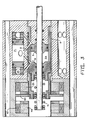
- Figure 1 shows the first quadrant of the hydraulic valve actuator shown in Figure 2 folded ninty degrees.
- Figure 1 consists of a shaft 1 coupled with a piston 5 in a cylinder 11 made up by sleeve 7 surrounded by valve 9 in main body 3.
- Cylinder 11 communicates with high pressure cylinder 21 through ports 17 and 15; also cylinder 11 communicates with low pressure cylinder 23 through ports 13 and 19.
- High pressure cylinder 21 is made up by main body 3 and has pistons 29 and 31 which are coupled to springs 25 and 27 respectively. Seals 33 are used to insure no leakage of fluid.
- the hydraulic valve actuator is an electronically controlled hydraulically powered valve actuator or transducer and includes a constant pressure source of high pressure fluid built around the pistons 29 and 31 and compression springs 27 and 25.
- the constant pressure source comprises a cylinder with the pair of spaced apart pistons 29 and 31 spring biased toward one another.
- a high pressure galley 22 is fed from a remote high pressure source (79 of Figure 11 and 12) and is coupled to the space intermediate the pistons and an arrangement including the bistable hydraulic fluid control valve 9 intermittently delivers high pressure fluid from the space intermediate the pistons and the pistons collapse toward one another due to the spring bias while maintaining the fluid pressure in chamber 21 as fluid exits the space.
- Figure 3 shows a low pressure galley which is a return line to the external source.
- the hydraulically actuated transducer has a transducer housing or main body 3 and a member or working piston 5 reciprocable within the housing along an axis.
- the piston has a pair of opposed primary working surfaces which define chambers 11a and 11b and receive hydraulic fluid pressure for moving the piston along the axis.
- a high pressure hydraulic fluid source 21 selectively supplies fluid to the piston faces under the control of a bistable hydraulic fluid control valve 9.
- Valve 9 is a shuttle valve reciprocable along the same axis as the piston and reciprocates relative to both the housing and the reciprocable member between first and second stable positions.
- An electronic control arrangement selectively actuates the control valve to move from one stable position to the other stable position to enable the flow of high pressure hydraulic fluid to one of the primary working surfaces.
- the hydraulic valve actuator uses electronic controlled magnetic latches.
- the latches consist of permanent magnets 35 and 49, coils 37 and 47, pole pieces 39 and 45; and armature 43.
- the latches are used to control the valve actuator by transferring armature 43 which is coupled to valve 9.
- Armature 43 and valve 9 are propelled by springs 51 and 53.
- Figure 2 shows the hydraulic valve actuator in cross-section where the galleys 28 and 30 that communicate high pressure to cylinder 11 are visible. Galleys 24 and 26 communicate low pressure to cylinder 11.
- Figure 1 is the first quadrant of Figure 2 folded ninety degrees.
- FIG 1 the piston 5 is shown in the closed right position (which corresponds to the engine valve being open) with the armature 43 and valve 9 closed.
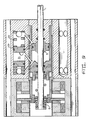
- Figure 3 shows the piston in that same closed rightmost position but armature 43 and valve 9 have traveled to their open position.
- the coil 47 was energized causing a build up of current and an electro-magnetic field that opposes the permanent magnet 49.
- the magnetic attraction force decreases enough the cocked spring 51 and the attractive force due to permanent magnet 35 accelerates armature 43 and valve 9 to their closed position.
- cylinder 11a is open to cylinder 23 through port 19 and the back side (right face) of piston 5 has high pressure fluid exposed to it from cylinder 21 through port 15.
- the high pressure in cylinder 11a begins to flow to cylinder 23 and the high pressure from cylinder 21 is now pressing on the backside of piston 5.
- Figure 4 shows piston 5 in the leftmost position.
- the high pressure fluid that was in cylinder 11a in Figure 3 has now caused spring 27 to open piston 31.
- the high pressure fluids from cylinder 21 in Figure 3 has now caused the piston 5 to travel to its left extreme position.
- Piston 5 moves very fast but the piston is shaped so that the fluid is compressed in the final thousandths of an inch allowing the valve to be properly damped.
- spring 53 has now been compressed by the movement of shaft 1 and is now ready for another transition.
- Figure 5 shows the piston 5 in the left open position with cylinder 11b open to cylinder 21 through port 15.
- piston 31 was opened by spring 27 and the high pressure fluid rushing into cylinder 11b.
- the low pressure fluid in chamber 23 is accepting the fluid from chamber 11a so as to additionally allow the motion of piston 5 and piston 31 in Figure 4 without necessarily requiring immediate flow in the external hydraulic source.
- the external source can recock the system.
- piston 31 has cocked the spring 27 and returned to its closed position through the use of the high pressure fluid in cylinder 21 which is maintained by use of an external pump.
- Spring 53 is also cocked leaving the actuator ready for another transition.
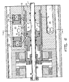
- Figure 6 shows the second quadrant of the hydraulic valve actuator shown in Figure 7 folded ninety degrees.
- Cylinder 11 communicates with high pressure cylinder 20 through ports 16 and 14; also cylinder 11 communicates with low pressure cylinder 23 through ports 12 and 18.
- Cylinder 20 is made up by main body 3 and has pistons 32 and 34 which are coupled to springs 36 and 38 respectively.
- the actuator is in the open position just as it was in Figure 5.
- Figure 6 illustrates the high pressure cylinder 22.The actuator is ready for another transition.
- Figure 7 shows the hydraulic valve actuator in cross-section along the line 7-7 of Figure 6.
- the galleys 28 and 30 that communicate high pressure to cylinder 11 are visible.
- Galleys 24 and 26 communicate low pressure to cylinder 11.
- Figure 6 is the second quadrant of Figure 7 folded ninety degrees.
- Figures 8-10 return to the first quadrant as shown by lines 1-1 of Figure 2.
- Figure 8 shows piston 5 in the middle of its transition from open to close.
- the coil 37 was energized causing a build up of current and an electro-magnetic field that opposes the permanent magnet 35.
- the magnetic attraction force decreases enough the cocked spring 53 and the attractive force due to permanent magnet 49 accelerates armature 43 and valve 9 to their closed positions.
- Ports 19 and 15 have been shut off by valve 9 and cylinder 11a now is open to high pressure cylinder 21 through port 17.
- the high pressure fluid on the left side of main piston 5 accelerates the piston to its right hand extreme position.
- the fluid on the right side of the main piston in chamber 11b rushes through port 13 and into cylinder 23 causing piston 29 to open.
- Piston 29 is being opened by the heavy spring 25 and the fluid from the right side of main piston 5.
- this spring 25 has been maintained in a compression stressed condition by the high pressure in chamber 21. Also, when port 17 is rapidly opened to allow flow from chamber 21 into chamber 11a, the left piston 31 can move to the right further closing chamber 21. This condition can exist depending on the pressure drop in chamber 21 and the degree of compression in spring 27. However, this movement will be somewhat smaller than that of piston 29 and is not depicted in Figure 8.
- the cylinders with the opposed spring biased pistons are much like the two faces of Janus.
- the facing piston surfaces move toward one another to supply high pressure fluid to the actuator while the oppositely facing outer piston surfaces move to expand the end volumes of the cylinder and provide a low resistance fluid sink for fluid exiting the actuator.
- the high pressure hydraulic fluid source for powering the valve actuator includes this variable volume chamber which lies closely adjacent the reciprocable member and separated therefrom by the control valve.
- the variable volume chamber is expanded by high pressure fluid and collapses upon the release of high pressure fluid therefrom to sustain the pressure as fluid flows into the transducer engaging a primary working surface of the piston.
- Figure 9 shows the main piston 5 in its closed (engine valve open) position.
- the high pressure from cylinder 21 has caused the main piston to travel to this position.
- the shape of main piston 5 helps to dampen the actuator motion when the piston starts to come to rest. The dampening is due to the shear forces in the captured fluid on the right side of piston 5. These shear forces are caused by the high fluid pressures existing during this period which causes the fluid to exit at high velocities.
- the spring 51 has also been compressed by the motion of shaft 1.
- Piston 29 has been fully opened by spring 25 and the fluid from the backside of piston 5 in cylinder 11b. The piston will re-cock spring 25 by using the high pressure in cylinder 21 and an external pump.
- Figure 10 is substantially the same as Figure 9 with the exception that piston 29 and spring 25 have been re-cocked by an external pump and the extension of main shaft 1 is connected directly to an intake or exhaust valve 65.
- the valve shaft and the actuator shaft are actually two shaft joined by a threaded coupling 63 and sharing axis 64. This facilitates alignment of the valve and valve actuator for the internal combustion engine.
- the axis 64 along which the power piston 5 reciprocates and the axis (also identified as 64) along which the poppet valve 65 reciprocates are colinear.
- Galley 55 which is used to drain the excess fluid accumulated in chambers 57 and 59. The fluid is generated from sliding valve 9. The excess fluid drains into galley 55 and is then returned back to the external pump.
- FIG 11 an illustrative transducer and valve 67 such as shown in Figure 10 are depicted with an internal combustion engine 71.
- This drawing also shows an engine driven high pressure hydraulic pump 79 which supplies fluid to the several valve actuators within the valve cover 81, a module 83 for sensing a plurality of engine operating values, e.g., responding to an engine RPM sensor 89, and an electronic control unit 93 for selectively energizing coils such as 37 and 47 as heretofor discussed.
- the functions of the electronic control units 83 and 93 may be combined into a single vehicle management computer.
- Figure 12 shows the hydraulic pump 79 supplying high pressure fluid to four individual actuators on the engine 71, however, the number of actuators may vary widely depending on the particular engine configuration.
- the hydraulic return 85 is shown in dotted lines in Figure 12.
Claims (7)
- Actionneur de soupape hydraulique à commande électronique comprenant:
un boîtier d'actionneur de soupape (3);
un piston asservi (5) mobile en va-et-vient dans le boîtier (3) suivant un axe;
une source de fluide hydraulique à haute pression (21; 79);
une valve de commande de fluide hydraulique bistable (9) mobile en va-et-vient le long dudit axe par rapport au boîtier (3) et au piston asservi (5) entre une première et une seconde position stable, le déplacement de la valve de commande (9) dans un sens d'une position stable vers l'autre position stable fournissant du fluide hydraulique depuis la source hydraulique à haute pression (21; 79) au piston asservi (5) qui est ainsi amené à se déplacer dans un sens opposé audit sens, la valve de commande (9) comprenant une douille cylindrique (7) coaxiale au piston asservi (5) et l'entourant au moins partiellement, et une armature (43) reliée à la douille (7) et réagissant à des champs magnétiques pour retenir la valve de commande (9) dans l'une ou l'autre de ses positions stables,
caractérisé en ce que la source de fluide hydraulique à haute pression (21; 79) comprend :
une source à pression constante et à faible volume de fluide sous haute pression comprenant au moins un cylindre (21), prévu à l'intérieur du boîtier (3), avec deux pistons espacés (29; 31) rappelés par ressort (25; 27) l'un vers l'autre et des moyens comprenant la valve de commande de fluide hydraulique bistable (9) pour fournir par intermittence du fluide sous haute pression depuis l'espace (21) prévu entre les pistons (29; 31), de sorte que les pistons (29; 31) se rapprochent l'un de l'autre sous l'effet de la sollicitation de ressort (25; 27) tout en maintenant la pression de fluide à mesure que le fluide s'échappe de l'espace (21). - Actionneur de soupape hydraulique à commande électronique suivant la revendication 1, dans lequel le cylindre (21) avec les deux pistons espacés (29; 31) fournit un dissipateur de fluide à basse pression et de faible volume dans l'espace en cours d'expansion (23) laissé en arrière lorsque des pistons (29; 31) se rapprochent l'un de l'autre.
- Actionneur de soupape hydraulique à commande électronique suivant la revendication 1 ou 2, comprenant deux cylindres (21; 20) chacun avec deux pistons espacés (29, 31; 32, 34), des ressorts (25, 27; 36, 38) rappelant les pistons (29, 31; 32, 34) de chaque paire l'un vers l'autre.
- Actionneur de soupape hydraulique à commande électronique suivant la revendication 1, 2 ou 3, comprenant deux aimants permanents (35; 49) coopérant avec l'armature (43) pour verrouiller la valve de commande (9) dans ses positions stables respectives et une paire correspondante de bobines (37; 47), chaque bobine (37; 47) pouvant être excitée pour au moins partiellement neutraliser le champ magnétique de l'aimant permanent associé (35; 49).
- Actionneur de soupape hydraulique à commande électronique suivant la revendication 1, 2, 3 ou 4, comprenant, en outre, des ressorts (51; 53) pour solliciter la valve de commande (9) dans un sens s'écartant de la position stable dans laquelle elle est verrouillée.
- Actionneur de soupape hydraulique à commande électronique suivant la revendication 5, dans lequel le ressort (51; 53) comprend au moins un ressort (51) relié à la valve de commande (9) et au piston asservi (5).
- Moteur à combustion interne dont chaque cylindre comprend au moins une soupape (65), caractérisé en ce que chaque soupape (65) est reliée à un actionneur de soupape hydraulique à commande électronique (67) suivant l'une quelconque des revendications 1 à 6.
Applications Claiming Priority (2)
| Application Number | Priority Date | Filing Date | Title |
|---|---|---|---|
| US07/457,015 US4974495A (en) | 1989-12-26 | 1989-12-26 | Electro-hydraulic valve actuator |
| US457015 | 1995-06-01 |
Publications (3)
| Publication Number | Publication Date |
|---|---|
| EP0443218A2 EP0443218A2 (fr) | 1991-08-28 |
| EP0443218A3 EP0443218A3 (en) | 1991-11-06 |
| EP0443218B1 true EP0443218B1 (fr) | 1994-05-04 |
Family
ID=23815084
Family Applications (1)
| Application Number | Title | Priority Date | Filing Date |
|---|---|---|---|
| EP19900203416 Expired - Lifetime EP0443218B1 (fr) | 1989-12-26 | 1990-12-18 | Actionneur de soupape électro-hydraulique |
Country Status (6)
| Country | Link |
|---|---|
| US (1) | US4974495A (fr) |
| EP (1) | EP0443218B1 (fr) |
| JP (1) | JPH04132810A (fr) |
| KR (1) | KR910012555A (fr) |
| CA (1) | CA2033027A1 (fr) |
| DE (1) | DE69008707D1 (fr) |
Families Citing this family (37)
| Publication number | Priority date | Publication date | Assignee | Title |
|---|---|---|---|---|
| DE69027858T2 (de) * | 1989-08-28 | 1997-02-13 | Nigel Eric Rose | Hydraulisches stellglied |
| US5058857A (en) * | 1990-02-22 | 1991-10-22 | Mark Hudson | Solenoid operated valve assembly |
| US5022358A (en) * | 1990-07-24 | 1991-06-11 | North American Philips Corporation | Low energy hydraulic actuator |
| GB9022439D0 (en) * | 1990-10-16 | 1990-11-28 | Lotus Car | A method and apparatus for testing an internal combustion engine |
| GB9022440D0 (en) * | 1990-10-16 | 1990-11-28 | Lotus Car | Engine valve control apparatus |
| US5125371A (en) * | 1991-04-04 | 1992-06-30 | North American Philips Corporation | Spring driven hydraulic actuator |
| US5255641A (en) | 1991-06-24 | 1993-10-26 | Ford Motor Company | Variable engine valve control system |
| US5248123A (en) * | 1991-12-11 | 1993-09-28 | North American Philips Corporation | Pilot operated hydraulic valve actuator |
| US5221072A (en) * | 1992-01-14 | 1993-06-22 | North American Philips Corporation | Resilient hydraulic actuator |
| US5529030A (en) * | 1992-02-26 | 1996-06-25 | Rose; Nigel E. | Fluid actuators |
| US5224683A (en) * | 1992-03-10 | 1993-07-06 | North American Philips Corporation | Hydraulic actuator with hydraulic springs |
| US5339777A (en) * | 1993-08-16 | 1994-08-23 | Caterpillar Inc. | Electrohydraulic device for actuating a control element |
| US5373817A (en) * | 1993-12-17 | 1994-12-20 | Ford Motor Company | Valve deactivation and adjustment system for electrohydraulic camless valvetrain |
| US6257499B1 (en) | 1994-06-06 | 2001-07-10 | Oded E. Sturman | High speed fuel injector |
| US6161770A (en) | 1994-06-06 | 2000-12-19 | Sturman; Oded E. | Hydraulically driven springless fuel injector |
| US5479901A (en) * | 1994-06-27 | 1996-01-02 | Caterpillar Inc. | Electro-hydraulic spool control valve assembly adapted for a fuel injector |
| US5540201A (en) * | 1994-07-29 | 1996-07-30 | Caterpillar Inc. | Engine compression braking apparatus and method |
| US5647318A (en) | 1994-07-29 | 1997-07-15 | Caterpillar Inc. | Engine compression braking apparatus and method |
| US5526784A (en) | 1994-08-04 | 1996-06-18 | Caterpillar Inc. | Simultaneous exhaust valve opening braking system |
| US5448973A (en) * | 1994-11-15 | 1995-09-12 | Eaton Corporation | Method of reducing the pressure and energy consumption of hydraulic actuators when activating engine exhaust valves |
| US5619965A (en) * | 1995-03-24 | 1997-04-15 | Diesel Engine Retarders, Inc. | Camless engines with compression release braking |
| US5570721A (en) * | 1995-03-29 | 1996-11-05 | Caterpillar Inc. | Double acting solenoid and poppet valve servomechanism |
| US6148778A (en) | 1995-05-17 | 2000-11-21 | Sturman Industries, Inc. | Air-fuel module adapted for an internal combustion engine |
| US6085991A (en) | 1998-05-14 | 2000-07-11 | Sturman; Oded E. | Intensified fuel injector having a lateral drain passage |
| US6024060A (en) | 1998-06-05 | 2000-02-15 | Buehrle, Ii; Harry W. | Internal combustion engine valve operating mechanism |
| US6604497B2 (en) | 1998-06-05 | 2003-08-12 | Buehrle, Ii Harry W. | Internal combustion engine valve operating mechanism |
| US6786186B2 (en) * | 1998-09-09 | 2004-09-07 | International Engine Intellectual Property Company, Llc | Unit trigger actuator |
| US6360721B1 (en) | 2000-05-23 | 2002-03-26 | Caterpillar Inc. | Fuel injector with independent control of check valve and fuel pressurization |
| SE520601C2 (sv) * | 1999-09-15 | 2003-07-29 | Scania Cv Ab | Anordning för att styra åtminstone en motorventil hos en förbränningsmotor |
| US6349686B1 (en) | 2000-08-31 | 2002-02-26 | Caterpillar Inc. | Hydraulically-driven valve and hydraulic system using same |
| DE10210158A1 (de) * | 2002-03-07 | 2003-09-18 | Bosch Gmbh Robert | Zylinder-Kolbentrieb |
| EP1536107A1 (fr) * | 2003-11-28 | 2005-06-01 | Thomas Friedhelm Buschkuehl | Dispositif d'actionnement de soupape de moteur à combustion interne, et procédé de commande |
| BRPI0622152A2 (pt) * | 2006-11-22 | 2014-07-08 | Volvo Lastvagnar Ab | Sistema de módulo para manufaturação de acionadores operados por fluido de duas e três posições estáveis |
| US9784147B1 (en) | 2007-03-07 | 2017-10-10 | Thermal Power Recovery Llc | Fluid-electric actuated reciprocating piston engine valves |
| FR3031134B1 (fr) * | 2014-12-26 | 2018-02-16 | Exel Industries | Moteur a air comprime et pompe comprenant un tel moteur |
| US10808858B2 (en) * | 2017-10-17 | 2020-10-20 | Automotive Technologies International, Inc. | High speed valve |
| DE102018222614A1 (de) * | 2018-12-20 | 2020-06-25 | Robert Bosch Gmbh | Elektromagnetische Betätigungseinrichtung |
Family Cites Families (11)
| Publication number | Priority date | Publication date | Assignee | Title |
|---|---|---|---|---|
| US3844528A (en) * | 1971-12-30 | 1974-10-29 | P Massie | Electrically operated hydraulic valve particularly adapted for pollution-free electronically controlled internal combustion engine |
| US3738337A (en) * | 1971-12-30 | 1973-06-12 | P Massie | Electrically operated hydraulic valve particularly adapted for pollution-free electronically controlled internal combustion engine |
| GB1591471A (en) * | 1977-06-18 | 1981-06-24 | Hart J C H | Electromagnetic actuators |
| US4749167A (en) * | 1979-12-03 | 1988-06-07 | Martin Gottschall | Two position mechanism |
| US4792291A (en) * | 1987-09-09 | 1988-12-20 | Graco Inc. | Viscous damped valve for hydraulic pump |
| US4878464A (en) * | 1988-02-08 | 1989-11-07 | Magnavox Government And Industrial Electronics Company | Pneumatic bistable electronic valve actuator |
| DE3806969A1 (de) * | 1988-03-03 | 1989-09-14 | Rexroth Mannesmann Gmbh | Elektrohydraulische stelleinrichtung zur betaetigung von gaswechselventilen bei brennkraftmaschinen |
| US4873948A (en) * | 1988-06-20 | 1989-10-17 | Magnavox Government And Industrial Electronics Company | Pneumatic actuator with solenoid operated control valves |
| US4852528A (en) * | 1988-06-20 | 1989-08-01 | Magnavox Government And Industrial Electronics Company | Pneumatic actuator with permanent magnet control valve latching |
| US4875441A (en) * | 1989-01-06 | 1989-10-24 | Magnavox Government And Industrial Electronics Company | Enhanced efficiency valve actuator |
| US4872425A (en) * | 1989-01-06 | 1989-10-10 | Magnavox Government And Industrial Electronics Company | Air powered valve actuator |
-
1989
- 1989-12-26 US US07/457,015 patent/US4974495A/en not_active Expired - Lifetime
-
1990
- 1990-12-18 EP EP19900203416 patent/EP0443218B1/fr not_active Expired - Lifetime
- 1990-12-18 DE DE69008707T patent/DE69008707D1/de not_active Expired - Lifetime
- 1990-12-21 CA CA 2033027 patent/CA2033027A1/fr not_active Abandoned
- 1990-12-24 KR KR1019900021582A patent/KR910012555A/ko not_active Application Discontinuation
- 1990-12-26 JP JP2414412A patent/JPH04132810A/ja active Pending
Also Published As
| Publication number | Publication date |
|---|---|
| EP0443218A3 (en) | 1991-11-06 |
| US4974495A (en) | 1990-12-04 |
| DE69008707D1 (de) | 1994-06-09 |
| KR910012555A (ko) | 1991-08-08 |
| CA2033027A1 (fr) | 1991-06-27 |
| JPH04132810A (ja) | 1992-05-07 |
| EP0443218A2 (fr) | 1991-08-28 |
Similar Documents
| Publication | Publication Date | Title |
|---|---|---|
| EP0443218B1 (fr) | Actionneur de soupape électro-hydraulique | |
| US5022358A (en) | Low energy hydraulic actuator | |
| US5248123A (en) | Pilot operated hydraulic valve actuator | |
| US5058538A (en) | Hydraulically propelled phneumatically returned valve actuator | |
| US4852528A (en) | Pneumatic actuator with permanent magnet control valve latching | |
| EP0328192A1 (fr) | Mécanisme de commande de soupape à énergie potentielle actionné par répulsion | |
| EP0507395A1 (fr) | Vérin pneumatique à haut rendement avec verrouillage hydraulique | |
| JPH0610629A (ja) | 電気制御液圧作動バルブアクチュエータ | |
| JPH07269318A (ja) | 対称式双安定性空気圧式アクチュエータ機構 | |
| US5221072A (en) | Resilient hydraulic actuator | |
| US5022359A (en) | Actuator with energy recovery return | |
| US5125371A (en) | Spring driven hydraulic actuator | |
| JP2005528563A5 (fr) | ||
| US4873948A (en) | Pneumatic actuator with solenoid operated control valves | |
| US4915015A (en) | Pneumatic actuator | |
| US4967702A (en) | Fast acting valve | |
| US4942852A (en) | Electro-pneumatic actuator | |
| US4899700A (en) | Pneumatically powered valve actuator | |
| US4991548A (en) | Compact valve actuator | |
| US4875441A (en) | Enhanced efficiency valve actuator | |
| US4872425A (en) | Air powered valve actuator | |
| US6997433B2 (en) | Electronic valve actuator having vibration cancellation |
Legal Events
| Date | Code | Title | Description |
|---|---|---|---|
| PUAI | Public reference made under article 153(3) epc to a published international application that has entered the european phase |
Free format text: ORIGINAL CODE: 0009012 |
|
| AK | Designated contracting states |
Kind code of ref document: A2 Designated state(s): DE ES FR GB IT SE |
|
| PUAL | Search report despatched |
Free format text: ORIGINAL CODE: 0009013 |
|
| AK | Designated contracting states |
Kind code of ref document: A3 Designated state(s): DE ES FR GB IT SE |
|
| 17P | Request for examination filed |
Effective date: 19920505 |
|
| 17Q | First examination report despatched |
Effective date: 19920703 |
|
| RAP1 | Party data changed (applicant data changed or rights of an application transferred) |
Owner name: MAGNAVOX ELECTRONIC SYSTEMS COMPANY |
|
| GRAA | (expected) grant |
Free format text: ORIGINAL CODE: 0009210 |
|
| AK | Designated contracting states |
Kind code of ref document: B1 Designated state(s): DE ES FR GB IT SE |
|
| PG25 | Lapsed in a contracting state [announced via postgrant information from national office to epo] |
Ref country code: IT Free format text: LAPSE BECAUSE OF FAILURE TO SUBMIT A TRANSLATION OF THE DESCRIPTION OR TO PAY THE FEE WITHIN THE PRE;WARNING: LAPSES OF ITALIAN PATENTS WITH EFFECTIVE DATE BEFORE 2007 MAY HAVE OCCURRED AT ANY TIME BEFORE 2007. THE CORRECT EFFECTIVE DATE MAY BE DIFFERENT FROM THE ONE RECORDED.SCRIBED TIME-LIMIT Effective date: 19940504 Ref country code: DE Effective date: 19940504 Ref country code: SE Effective date: 19940504 Ref country code: ES Free format text: THE PATENT HAS BEEN ANNULLED BY A DECISION OF A NATIONAL AUTHORITY Effective date: 19940504 Ref country code: FR Effective date: 19940504 |
|
| REF | Corresponds to: |
Ref document number: 69008707 Country of ref document: DE Date of ref document: 19940609 |
|
| EN | Fr: translation not filed | ||
| PG25 | Lapsed in a contracting state [announced via postgrant information from national office to epo] |
Ref country code: GB Effective date: 19941218 |
|
| EUG | Se: european patent has lapsed |
Ref document number: 90203416.4 Effective date: 19940422 |
|
| PLBE | No opposition filed within time limit |
Free format text: ORIGINAL CODE: 0009261 |
|
| STAA | Information on the status of an ep patent application or granted ep patent |
Free format text: STATUS: NO OPPOSITION FILED WITHIN TIME LIMIT |
|
| 26N | No opposition filed | ||
| GBPC | Gb: european patent ceased through non-payment of renewal fee |
Effective date: 19941218 |