EP0442161B1 - Device for projecting television pictures - Google Patents
Device for projecting television pictures Download PDFInfo
- Publication number
- EP0442161B1 EP0442161B1 EP90203387A EP90203387A EP0442161B1 EP 0442161 B1 EP0442161 B1 EP 0442161B1 EP 90203387 A EP90203387 A EP 90203387A EP 90203387 A EP90203387 A EP 90203387A EP 0442161 B1 EP0442161 B1 EP 0442161B1
- Authority
- EP
- European Patent Office
- Prior art keywords
- arm
- lcd
- adjustment
- shaped
- light
- Prior art date
- Legal status (The legal status is an assumption and is not a legal conclusion. Google has not performed a legal analysis and makes no representation as to the accuracy of the status listed.)
- Expired - Lifetime
Links
Images

Classifications
-
- H—ELECTRICITY
- H04—ELECTRIC COMMUNICATION TECHNIQUE
- H04N—PICTORIAL COMMUNICATION, e.g. TELEVISION
- H04N5/00—Details of television systems
- H04N5/74—Projection arrangements for image reproduction, e.g. using eidophor
-
- H—ELECTRICITY
- H04—ELECTRIC COMMUNICATION TECHNIQUE
- H04N—PICTORIAL COMMUNICATION, e.g. TELEVISION
- H04N9/00—Details of colour television systems
- H04N9/12—Picture reproducers
- H04N9/31—Projection devices for colour picture display, e.g. using electronic spatial light modulators [ESLM]
- H04N9/3141—Constructional details thereof
- H04N9/317—Convergence or focusing systems
-
- Y—GENERAL TAGGING OF NEW TECHNOLOGICAL DEVELOPMENTS; GENERAL TAGGING OF CROSS-SECTIONAL TECHNOLOGIES SPANNING OVER SEVERAL SECTIONS OF THE IPC; TECHNICAL SUBJECTS COVERED BY FORMER USPC CROSS-REFERENCE ART COLLECTIONS [XRACs] AND DIGESTS
- Y10—TECHNICAL SUBJECTS COVERED BY FORMER USPC
- Y10S—TECHNICAL SUBJECTS COVERED BY FORMER USPC CROSS-REFERENCE ART COLLECTIONS [XRACs] AND DIGESTS
- Y10S353/00—Optics: image projectors
- Y10S353/05—Transparency holder accessories
Definitions
- the invention relates to a device for projecting television pictures, provided with a light source and dichroic mirrors which separate the light into three channels, the light being guided through an LCD in each channel, after which the light transmitted by the LCDs in the different channels is united by means of dichroic mirrors into a single channel to be supplied to a projection systems, each LCD being mounted to a common support member.
- Such a device is known from JP-A-63-116123.
- the light coming from a light source is separated into different colour components, such as red, green and blue, in three separate channels by means of dichroic mirrors.
- the light beams of different colours running in different channels and obtained in this way are then conducted through liquid crystal display units having two polaroids (referred to as LCDs hereinafter), which are known per se.
- LCDs are controlled by control means which are known per se, which are immaterial to the invention, and which will therefore not be described any further, in such a way that only desired portions of the light beams are transmitted in the various channels.
- the light beams thus transmitted by the LCDs are merged together again by means of dichroic mirrors into a single channel, and the combined light beam thus obtained is fed to a projection system for projecting the desired picture.
- the LCDs are mounted to a common support member or housing in which the light beams passing through the LCDs are to be combined by means of dichroic mirrors positioned in this support member or housing.
- this object can be achieved in that relative to the support member one of the LCDs occupies a fixed position while the two other LCDs are each connected to the support member by means of three adjustment members, the three adjustment members coupled to an LCD making contact with the relevant LCD in three coupling points which, seen in the movement of direction of the light through the relevant LCD, are staggered through subsequent angles of 90° relative to one another, so that each LCD is adjustable by means of each of the three adjustment members, one adjustment member for adjustment in a direction parallel to the direction of movement of the light through the relevant LCD, the other two adjustment members for adjustment in two mutually perpendicular directions which are perpendicular to the direction of movement of the light through the relevant LCD.
- a device for projecting television pictures in which light beams through three projection systems are projected in one point on a screen by means of three objectives.
- the device comprises adjustment means for mirrors, LCDs and lenses.
- the light beams are not merged together into a single channel. There is no further indication about the adjustment means.
- the LCD fixedly connected to the support member may be used as a reference member relative to which the other LCDs are brought into the correct position by means of the adjustment members coupled to the relevant LCDs. It has been found in practice that an accurate alignment of the LCDs can be achieved in this way, so that the separate pictures formed at the LCDs can be projected over one another in the correct manner.
- a further aspect of the invention relates to a device for fixing a disc-shaped member relative to a plate-shaped wall portion of a support member enclosing the disc-shaped member.
- the disc-shaped member or mirror can be inserted in the slot and a swivel movement of the finger-shaped member can be achieved through deformation of the two connection parts enclosing an angle with one another, in such a way that the free end of the said finger-shaped member presses the disc-shaped member against the bounding edge of the slot positioned opposite the free end of the finger-shaped member.
- a fixation of the disc-shaped member relative to the plate-shaped wall portion is thereby obtained in a simple manner owing to the permanent deformation of the connection parts enclosing an angle with one another without additional fastening means, which often form inconvenient obstacles, being necessary for this.
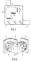
- Fig. 1 shows a rectangular housing 1 to whose side wall a lamp housing 2 is mounted, by means of which light can be radiated into the interior of the housing through an opening provided in the relevant wall.
- Three dichroic mirrors 3, 4 and 5 are positioned one after the other in the housing 1 in the light path of lamp housing 2. In known manner, these mirrors transmit only part of the incident light, while, seen in Fig. 1, part of the light incident on the mirrors in horizontal direction from the lamp housing 2 is deflected in vertical direction so that, for example, an upwardly directed channel of blue light is formed at mirror 3, an upwardly directed channel of green light is formed at mirror 4, and an upwardly directed channel of red light is formed at mirror 5.
- the light coming from the mirror 3 is deflected by a further mirror in the direction of a lens 7.
- the light deflected by the mirrors 4 and 5 is incident on lenses 8 and 9, respectively.
- the parallel centrelines of the lenses 8 and 9 extend in a direction perpendicular to the centreline of the lens 7.
- the lenses 7, 8 and 9 are positioned near wall portions of a housing 10 which is accommodated in the housing 1 and has a more or less L-shaped construction, which wall portions extend parallel to the said lenses.
- this housing 10 also called recombination housing, the light beams transmitted by the lenses 7, 8 and 9 in the housing are joined together again in a way yet to be described below and supplied as a single beam to a projection system 111 mounted to the housing, with which system a picture can be projected.
- LCDs 11-13 are mounted to the wall portions of the housing 10 situated opposite the lenses 7-9.
- the LCD 12 situated opposite the lens 8 occupies a fixed position relative to the housing 10 whereas the LCDs 11 and 13 are adjustable relative to the housing by means of adjustment members 14.
- Three adjustment members 14 are provided for the LCD 11 as well as for the LCD 13, which members are provided on three outer walls of the housing 10 which enclose subsequent angles of 90° with one another.
- the adjustment member comprises a first elongate leg 15 in whose free end a U-shaped recess 16 is provided.
- the width of the leg gradually decreases in the direction of a rectangular intermediate portion 17 of the leg, which portion is slightly depressed relative to the portions of the leg 15 situated on either side of it.
- connection piece 18 which at its side facing away from the leg 15 adjoins a substantially rectangular plate-shape portion 19.
- connection piece 18 is slightly depressed relative to the portions 15 and 19 which are integral with it and are situated on either side of it.
- connection piece By means of a connection ridge 20, whose width is considerably smaller than that of the connection piece 18, the connection piece is connected to the end of a leg 21 which extends substantially parallel to the leg 15 between the leg 15 and the plate-shape portion 19, and whose width is approximately equal to the width of the connection piece 18.
- connection ridge 22 whose dimensions correspond to those of the connection ridge 20
- the free end of the leg 21 is connected to a substantially U-shaped coupling piece 23, which is situated at approximately the same level as the free end of the leg 15 provided with the U-shaped recess 16.
- the leg 21 is in one plane with the portion 18 and will thus lie at a distance from the wall of the housing 10 in the assembled state.
- connection piece 19 a slot 24 extending parallel to the longitudinal direction of the connection piece is provided in the plate-shaped portion 19 near the connection piece 18, so that the plate-shaped portion is in fact only connected to the connection piece via a connection ridge 25, whose dimensions correspond to those of the connection ridges 20 and 22.
- the plate-shape portion has an extension 26 merging into an arm 27, which arm forms a connection between the end of the extension 26 and a plate portion 29 provided with a U-shaped recess 28.
- the arm 27 is again slightly depressed relative to the portions 29 and 26 situated on either side of it.
- a wedge-shaped opening 30 extending from a side of the extension 26 in the direction of the arm 21 is provided in the extension 26. Above this wedge-shaped opening 30, a circular hole 31 is formed in the extension 26, which hole merges into a slot 32 which extends from the boundary of the extension 26 facing the leg 21 to the hole 31.
- a connection piece 33 is formed in this way, connected at one end to the end of the extension 26 by means of a connection ridge 34 of small cross-section and at its other end to the end of a connection arm, which is built up of two portions 36 and 37 depressed relative to one another, by means of a connection ridge 35 of small cross-section.
- the portion 37 here lies in one plane with the depressed portions 18 and 21.
- connection pieces 38 and 39 merge into the end of the connection arm 36, 37 remote from the connection piece 33 via connection ridges 40 and 41, respectively, of comparatively small cross-section at the side of the connection arm facing away from the connection piece 33.
- connection piece 38 is connected to a side of the arm 21 near the centre of this arm by means of a further connection ridge 42 of small cross-section.
- connection piece 39 is connected to an edge of the plate-shaped portion 19 along an edge which extends perpendicularly to the arm 21.
- the plate-shaped portion 19 further accommodates two holes 43 and 44 through which screws, rivets, or the like can be inserted, by means of which the plate-shaped section 19 of the adjustment member 14 manufactured from a plate-shaped piece of material may be mounted to a wall of the housing 10 in the manner represented in Figs. 2 and 7.
- the depressed portion 17 is situated below a U-shaped bracket 45 which straddles this depressed portion 17 and is integral with the wall of the housing 10, against which bracket the depressed portion 17 is forcably pressed owing to the shape of the adjustment member 14.
- the depressed arm 27 is situated below a U-shaped bracket 46 which is integral with the wall of the housing 10, against which bracket the arm 27 is also forcibly pressed.
- one or several bores 47, 48, respectively, is/are provided in the wall of the housing 10 at the level of the U-shaped recesses 16 and 28 for a purpose yet to be described below.
- an adjustable LCD 11 is connected to a connection plate 49 which is surrounded by a dust rising 50.
- the LCD is further screened with transparent cover plates 51 mounted to a cooling frame 52.
- the connection plate 49 is coupled to the relevant three adjustment members 14 by means of bolts 53 which are inserted through the holes provided in the connection plate and screwed into the U-shaped coupling pieces 23, so that the connection plate, and thus the relevant LCD 11 is supported in three coupling points by adjustment members 14, the coupling points being positioned at subsequent angles of 90° relative to one another seen in the direction in which a light beam moves through the LCD.
- adjustment members 14 are provided on the outside of the housing 10, they are easily accessible.
- Such a displacement can be achieved by means of a peg whose diameter corresponds approximately to the width of the recess 16 or 28.
- a pin is provided at the bottom end of this peg in a position eccentric relative to the centreline of the peg and fitting in the bores 47 and 48.
- connection ridge 25 When the free end of the arm 15 is displaced in the direction of arrow A, the arm 15 will rotate relative to the remaining portion of the adjustment member 14 about a pivot point formed by the connection ridge 25.
- the rotation about the pivot point 25 displaces the connection piece 18 and the leg 21 connected to it at least substantially in longitudinal direction of this leg 21, which movement of the leg 21 is made possible in that a hinging movement can also occur in the connection ridges 40 and 42. It will be obvious that a displacement of the leg 21 in its longitudinal direction leads to a corresponding displacement of the coupling point by which the leg 21 is coupled to the connection plate 49 supporting the relevant LCD.
- this plate portion 29 is shifted in one of the two directions of arrow B, this plate portion together with the arm 27 will swivel about a pivot point formed by connection ridge 54 between the hole 31 and the inner end of the wedge-shaped opening 30.
- This movement of the arm 27 is transmitted by the connection piece 33 to the connection arm 36, 37, which will consequently swivel about the pivot point formed by the connection ridge 41.
- This swivel movement of the arm 36, 37 is transmitted again by the connection piece 38 to the leg 21, so that this leg 21 will swivel about the pivot point formed by the connection ridge 20.
- the use of the adjustment member renders it possible to achieve a displacement in two mutually perpendicular directions at the location of the coupling point between the adjustment member 14 and a connection plate 49 supporting a relevant LCD. Since each connection plate 49 supporting an LCD is connected to an adjustment member 14 in three points shifted 90° relative to one another, such a displacement can be achieved in two mutually perpendicular directions in these three points, so that it is possible to set the relevant LCD in any desired position. Thus it is possible to adjust the two adjustable LCDs in such a way that the pictures formed in these LCDs will coincide correctly with the picture formed by the LCD with fixed position, which serves as a reference.
- the design of the adjustment member 14 achieves that the displacement of the free end of the leg 15 causes a considerably smaller displacement of the leg 21 in its longitudinal direction; in the embodiment shown the ratio of these displacements is approximately 1 : 10.
- the displacement of the plate-shaped portion 29 in the direction of arrow B in the chosen embodiment of the adjustment member 14 also results in a considerably smaller displacement of the coupling piece 23; in the embodiment shown the ratio of these displacements is approximately 1 : 10.
- Fig. 8 shows diagrammatically the way in which an edge of a disc-shaped member, such as a mirror 55, may be fixed in a plate-shaped wall 56 of a housing.
- the boundary of the mirror 55 facing away from the wall 56 may, for example, be inserted in brackets or the like which are fastened to a side wall of the relevant housing situated opposite the wall 56.
- the mirror 55 is inserted in a slot 57 provided in the wall 56.
- a recess 58 provided in the wall 56 merges into this slot.
- a finger-shaped member 59 which is integral with the wall 56 and of which only one end is connected to the remaining portion of the plate-shaped member 56 by means of a connection ridge 60.
- the finger-shaped member 59 is further connected to the plate-shaped portion by means of two connection parts 61 and 62 which together enclose an angle and which are also integral with the finger-shaped member 59 and the wall 56.
- the finger-shaped member is provided with a nose 63 extending towards the mirror 55 at its free end facing away from the connection ridge 60. This nose 63 is situated opposite a projection 64 of the boundary of the slot 57, which lies at the side of the mirror 55 facing away from the nose 63.
- That portion of the finger-shaped member 59 which is situated between the connection parts 61 and 62 enclosing an angle with one another on the one hand and the projecting nose 63 on the other hand is of a narrower design over part 65 of its length than the remaining part of the finger-shaped member 59.
- the finger-shaped member 59 with its associated parts will initially be stamped out from the material of the wall 56 in the shape represented in Fig. 8. After insertion of the mirror 55, the two connection pieces enclosing an angle can be deformed with a suitable tool in such a way that the angle enclosed by these parts 61 and 62 will become greater. As a result the finger-shaped member 59 will swivel relative to the wall 56 about the pivot point formed by the connection ridge 60. Thus the nose 63 will be forced towards the mirror 55, so that the mirror 55 is clamped between the nose 63 and the projection 64. Owing to the narrower portion 65 of the finger-shaped member 59, the finger-shaped member 59 will possess a certain resilience, by which the exertion of undesirably high forces on the mirror 55 is prevented.
Description
- The invention relates to a device for projecting television pictures, provided with a light source and dichroic mirrors which separate the light into three channels, the light being guided through an LCD in each channel, after which the light transmitted by the LCDs in the different channels is united by means of dichroic mirrors into a single channel to be supplied to a projection systems, each LCD being mounted to a common support member.
- Such a device is known from JP-A-63-116123. In these kind of TV projection systems the light coming from a light source is separated into different colour components, such as red, green and blue, in three separate channels by means of dichroic mirrors.
- The light beams of different colours running in different channels and obtained in this way are then conducted through liquid crystal display units having two polaroids (referred to as LCDs hereinafter), which are known per se. The LCDs are controlled by control means which are known per se, which are immaterial to the invention, and which will therefore not be described any further, in such a way that only desired portions of the light beams are transmitted in the various channels. The light beams thus transmitted by the LCDs are merged together again by means of dichroic mirrors into a single channel, and the combined light beam thus obtained is fed to a projection system for projecting the desired picture.
- The LCDs are mounted to a common support member or housing in which the light beams passing through the LCDs are to be combined by means of dichroic mirrors positioned in this support member or housing.
- It is necessary here that the pictures formed by the three separate LCDs by means of the transmitted light should be projected in the correct manner, overlapping one another in order to achieve a sharp and clear picture. For this purpose it it required that the LCDs are correctly aligned relative to one another during the assembly of the device.
- According to the invention this object can be achieved in that relative to the support member one of the LCDs occupies a fixed position while the two other LCDs are each connected to the support member by means of three adjustment members, the three adjustment members coupled to an LCD making contact with the relevant LCD in three coupling points which, seen in the movement of direction of the light through the relevant LCD, are staggered through subsequent angles of 90° relative to one another, so that each LCD is adjustable by means of each of the three adjustment members, one adjustment member for adjustment in a direction parallel to the direction of movement of the light through the relevant LCD, the other two adjustment members for adjustment in two mutually perpendicular directions which are perpendicular to the direction of movement of the light through the relevant LCD.
- From DE-U-88 15 708 a device for projecting television pictures is known in which light beams through three projection systems are projected in one point on a screen by means of three objectives. The device comprises adjustment means for mirrors, LCDs and lenses. In this device the light beams are not merged together into a single channel. There is no further indication about the adjustment means.
- When the construction according to the invention is used, the LCD fixedly connected to the support member may be used as a reference member relative to which the other LCDs are brought into the correct position by means of the adjustment members coupled to the relevant LCDs. It has been found in practice that an accurate alignment of the LCDs can be achieved in this way, so that the separate pictures formed at the LCDs can be projected over one another in the correct manner.
- A further aspect of the invention relates to a device for fixing a disc-shaped member relative to a plate-shaped wall portion of a support member enclosing the disc-shaped member. In the mounting of disc-shaped members, particularly in the fastening of mirrors, such as, for example, those used in the projection device described above, it is important that the disc-shaped member or mirror can be fixed in the desired position in a simple manner.
- According to the invention, this can be achieved in that a slot is provided in the plate-shaped wall portion for accomodating the disc-shaped member, and in that an oblong, finger-shaped member is stamped from the plate-shaped wall portion at the level of the slot in such a way that this finger-shaped member is connected to the remaining portion of the plate-shaped wall portion only with one end and, between its ends, with two connection parts which enclose an angle with one another. When the construction according to the invention is used, the disc-shaped member or mirror can be inserted in the slot and a swivel movement of the finger-shaped member can be achieved through deformation of the two connection parts enclosing an angle with one another, in such a way that the free end of the said finger-shaped member presses the disc-shaped member against the bounding edge of the slot positioned opposite the free end of the finger-shaped member. A fixation of the disc-shaped member relative to the plate-shaped wall portion is thereby obtained in a simple manner owing to the permanent deformation of the connection parts enclosing an angle with one another without additional fastening means, which often form inconvenient obstacles, being necessary for this.
- The invention will be explained in more detail below with reference to a possible embodiment of the construction according to the invention as pictured in the accompanying Figures.
- Fig. 1 shows diagrammatically an embodiment of a device according to the invention, partly in elevation and partly in cross-section,
- Fig. 2 shows diagrammatically a perspective view of a housing with LCDs and adjustment members for the LCDs mounted to it,
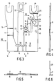
- Fig. 3 shows a plan view of an embodiment of an adjustment member according to the invention,
- Fig. 4 shows a side elevation of Fig. 3 viewed along the arrow IV in Fig. 3,
- Fig. 5 shows an elevation of Fig. 3 viewed along the arrow V in Fig. 3,
- Fig. 6 shows part of the adjustment member represented in Fig. 3 viewed along the arrow VI in Fig. 3,
- Fig. 7 shows part of the housing represented in Fig. 2 on a larger scale, partly in plan view and partly in cross-section,
- Fig. 8 shows the fastening of a disc-shaped member in a plate-shaped wall portion.
- Fig. 1 shows a rectangular housing 1 to whose side wall a lamp housing 2 is mounted, by means of which light can be radiated into the interior of the housing through an opening provided in the relevant wall. Three
dichroic mirrors 3, 4 and 5 are positioned one after the other in the housing 1 in the light path of lamp housing 2. In known manner, these mirrors transmit only part of the incident light, while, seen in Fig. 1, part of the light incident on the mirrors in horizontal direction from the lamp housing 2 is deflected in vertical direction so that, for example, an upwardly directed channel of blue light is formed at mirror 3, an upwardly directed channel of green light is formed at mirror 4, and an upwardly directed channel of red light is formed atmirror 5. - The light coming from the mirror 3 is deflected by a further mirror in the direction of a lens 7. The light deflected by the
mirrors 4 and 5 is incident on lenses 8 and 9, respectively. - As is evident from Fig. 1, the parallel centrelines of the lenses 8 and 9 extend in a direction perpendicular to the centreline of the lens 7. The lenses 7, 8 and 9 are positioned near wall portions of a
housing 10 which is accommodated in the housing 1 and has a more or less L-shaped construction, which wall portions extend parallel to the said lenses. In thishousing 10, also called recombination housing, the light beams transmitted by the lenses 7, 8 and 9 in the housing are joined together again in a way yet to be described below and supplied as a single beam to aprojection system 111 mounted to the housing, with which system a picture can be projected. - As is shown diagrammatically in Fig. 2, LCDs 11-13 are mounted to the wall portions of the
housing 10 situated opposite the lenses 7-9. TheLCD 12 situated opposite the lens 8 occupies a fixed position relative to thehousing 10 whereas theLCDs adjustment members 14. Threeadjustment members 14 are provided for theLCD 11 as well as for theLCD 13, which members are provided on three outer walls of thehousing 10 which enclose subsequent angles of 90° with one another. - An embodiment of an
adjustment member 14 will be explained in greater detail below with reference to the Figs. 3-6. The adjustment member comprises a firstelongate leg 15 in whose free end aU-shaped recess 16 is provided. - From the end comprising the
recess 16, the width of the leg gradually decreases in the direction of a rectangularintermediate portion 17 of the leg, which portion is slightly depressed relative to the portions of theleg 15 situated on either side of it. - The remaining portion of the
leg 15 again gradually increases in width and with one side adjoins aconnection piece 18, which at its side facing away from theleg 15 adjoins a substantially rectangular plate-shape portion 19. As is particularly apparent from Fig. 5, theconnection piece 18 is slightly depressed relative to theportions - By means of a
connection ridge 20, whose width is considerably smaller than that of theconnection piece 18, the connection piece is connected to the end of aleg 21 which extends substantially parallel to theleg 15 between theleg 15 and the plate-shape portion 19, and whose width is approximately equal to the width of theconnection piece 18. - By means of a
connection ridge 22, whose dimensions correspond to those of theconnection ridge 20, the free end of theleg 21 is connected to a substantially U-shapedcoupling piece 23, which is situated at approximately the same level as the free end of theleg 15 provided with theU-shaped recess 16. - The
leg 21 is in one plane with theportion 18 and will thus lie at a distance from the wall of thehousing 10 in the assembled state. - As is further apparent from Fig. 3, a
slot 24 extending parallel to the longitudinal direction of the connection piece is provided in the plate-shaped portion 19 near theconnection piece 18, so that the plate-shaped portion is in fact only connected to the connection piece via aconnection ridge 25, whose dimensions correspond to those of theconnection ridges - At its side facing away from the
leg 21, the plate-shape portion has anextension 26 merging into anarm 27, which arm forms a connection between the end of theextension 26 and aplate portion 29 provided with aU-shaped recess 28. As is particularly apparent from Fig. 6, thearm 27 is again slightly depressed relative to theportions - A wedge-
shaped opening 30 extending from a side of theextension 26 in the direction of thearm 21 is provided in theextension 26. Above this wedge-shaped opening 30, acircular hole 31 is formed in theextension 26, which hole merges into aslot 32 which extends from the boundary of theextension 26 facing theleg 21 to thehole 31. Aconnection piece 33 is formed in this way, connected at one end to the end of theextension 26 by means of aconnection ridge 34 of small cross-section and at its other end to the end of a connection arm, which is built up of twoportions connection ridge 35 of small cross-section. Theportion 37 here lies in one plane with thedepressed portions - Two
further connection pieces connection arm connection piece 33 viaconnection ridges connection piece 33. - The
connection piece 38 is connected to a side of thearm 21 near the centre of this arm by means of afurther connection ridge 42 of small cross-section. - The
connection piece 39 is connected to an edge of the plate-shaped portion 19 along an edge which extends perpendicularly to thearm 21. - The plate-
shaped portion 19 further accommodates twoholes shaped section 19 of theadjustment member 14 manufactured from a plate-shaped piece of material may be mounted to a wall of thehousing 10 in the manner represented in Figs. 2 and 7. - The arrangement is such for this purpose that the
depressed portion 17 is situated below a U-shapedbracket 45 which straddles thisdepressed portion 17 and is integral with the wall of thehousing 10, against which bracket thedepressed portion 17 is forcably pressed owing to the shape of theadjustment member 14. In a similar way, thedepressed arm 27 is situated below a U-shapedbracket 46 which is integral with the wall of thehousing 10, against which bracket thearm 27 is also forcibly pressed. Furthermore, one orseveral bores housing 10 at the level of the U-shapedrecesses - As is further apparent from Fig. 7, an
adjustable LCD 11 is connected to aconnection plate 49 which is surrounded by a dust rising 50. At the side facing away from thehousing 10, the LCD is further screened withtransparent cover plates 51 mounted to acooling frame 52. Theconnection plate 49 is coupled to the relevant threeadjustment members 14 by means ofbolts 53 which are inserted through the holes provided in the connection plate and screwed into theU-shaped coupling pieces 23, so that the connection plate, and thus therelevant LCD 11 is supported in three coupling points byadjustment members 14, the coupling points being positioned at subsequent angles of 90° relative to one another seen in the direction in which a light beam moves through the LCD. - Since the
adjustment members 14 are provided on the outside of thehousing 10, they are easily accessible. - To carry out an adjustment of the coupling point between an
adjustment member 14 and theconnection plate 49 supporting an LCD, which coupling point is formed by abolt 53, the end of thearm 15 comprising therecess 16 is shifted to the left or to the right as shown with arrow A and/or theplate portion 29 comprising therecess 28 is shifted to the left or to the right as shown with arrow B. - Such a displacement can be achieved by means of a peg whose diameter corresponds approximately to the width of the
recess bores - It will be clear that, when the pin is inserted into one of the
bores recess arm 15 or the plate-shapedportion 29 will be displaced in one of the two directions represented by the arrow A or the arrow B, respectively, as seen in Fig. 7. - When the free end of the
arm 15 is displaced in the direction of arrow A, thearm 15 will rotate relative to the remaining portion of theadjustment member 14 about a pivot point formed by theconnection ridge 25. The rotation about thepivot point 25 displaces theconnection piece 18 and theleg 21 connected to it at least substantially in longitudinal direction of thisleg 21, which movement of theleg 21 is made possible in that a hinging movement can also occur in theconnection ridges leg 21 in its longitudinal direction leads to a corresponding displacement of the coupling point by which theleg 21 is coupled to theconnection plate 49 supporting the relevant LCD. - Owing to the frictional force generated between the
depressed portion 17 and thebracket 45, theleg 15, and thus theleg 21 and the coupling point between thisleg 21 and theconnection plate 49 will remain in a once set position. - If the
plate portion 29 is shifted in one of the two directions of arrow B, this plate portion together with thearm 27 will swivel about a pivot point formed byconnection ridge 54 between thehole 31 and the inner end of the wedge-shapedopening 30. This movement of thearm 27 is transmitted by theconnection piece 33 to theconnection arm connection ridge 41. This swivel movement of thearm connection piece 38 to theleg 21, so that thisleg 21 will swivel about the pivot point formed by theconnection ridge 20. It will be clear that such a swivel movement of thearm 21 at the coupling point formed by thebolt 53 will lead to a displacement of theconnection plate 49 supporting the LCD in a direction perpendicular to the longitudinal direction of thearm 21. Here, too, the once set position of thearm 27, and thus the set position of the parts connected to thearm 27, will be maintained by the frictional force generated between thearm 27 and thebracket 46. - The use of the adjustment member renders it possible to achieve a displacement in two mutually perpendicular directions at the location of the coupling point between the
adjustment member 14 and aconnection plate 49 supporting a relevant LCD. Since eachconnection plate 49 supporting an LCD is connected to anadjustment member 14 in three points shifted 90° relative to one another, such a displacement can be achieved in two mutually perpendicular directions in these three points, so that it is possible to set the relevant LCD in any desired position. Thus it is possible to adjust the two adjustable LCDs in such a way that the pictures formed in these LCDs will coincide correctly with the picture formed by the LCD with fixed position, which serves as a reference. - Thanks to the plate-shaped design of the
adjustment member 14, this adjustment member will occupy little space and thus contribute to the compactness of the construction of the device in which the adjustment member is used. Furthermore, the design of theadjustment member 14 achieves that the displacement of the free end of theleg 15 causes a considerably smaller displacement of theleg 21 in its longitudinal direction; in the embodiment shown the ratio of these displacements is approximately 1 : 10. The displacement of the plate-shapedportion 29 in the direction of arrow B in the chosen embodiment of theadjustment member 14 also results in a considerably smaller displacement of thecoupling piece 23; in the embodiment shown the ratio of these displacements is approximately 1 : 10. - In addition, Fig. 8 shows diagrammatically the way in which an edge of a disc-shaped member, such as a
mirror 55, may be fixed in a plate-shapedwall 56 of a housing. The boundary of themirror 55 facing away from thewall 56 may, for example, be inserted in brackets or the like which are fastened to a side wall of the relevant housing situated opposite thewall 56. - As is shown in Fig. 8, the
mirror 55 is inserted in aslot 57 provided in thewall 56. Arecess 58 provided in thewall 56 merges into this slot. In this recess is present a finger-shapedmember 59 which is integral with thewall 56 and of which only one end is connected to the remaining portion of the plate-shapedmember 56 by means of aconnection ridge 60. Between its ends, the finger-shapedmember 59 is further connected to the plate-shaped portion by means of twoconnection parts member 59 and thewall 56. The finger-shaped member is provided with anose 63 extending towards themirror 55 at its free end facing away from theconnection ridge 60. Thisnose 63 is situated opposite aprojection 64 of the boundary of theslot 57, which lies at the side of themirror 55 facing away from thenose 63. - That portion of the finger-shaped
member 59 which is situated between theconnection parts nose 63 on the other hand is of a narrower design overpart 65 of its length than the remaining part of the finger-shapedmember 59. - The finger-shaped
member 59 with its associated parts will initially be stamped out from the material of thewall 56 in the shape represented in Fig. 8. After insertion of themirror 55, the two connection pieces enclosing an angle can be deformed with a suitable tool in such a way that the angle enclosed by theseparts member 59 will swivel relative to thewall 56 about the pivot point formed by theconnection ridge 60. Thus thenose 63 will be forced towards themirror 55, so that themirror 55 is clamped between thenose 63 and theprojection 64. Owing to thenarrower portion 65 of the finger-shapedmember 59, the finger-shapedmember 59 will possess a certain resilience, by which the exertion of undesirably high forces on themirror 55 is prevented. - It will be clear that a fixation of the rim of the
mirror 55 present in theslot 57 of thewall 56 can be quickly and effectively achieved in this way without loose and/or projecting components being require, so that an inexpensive and compact design is obtained.
Claims (11)
- A device for projecting television pictures provided with a light source and dichroic mirrors (3,4,5) which separate the light into three channels, the light being guided through an LCD (11,12,13) in each channel, after which the light transmitted by the LCDs in the different channels is united by means of dichroic mirrors into a single channel to be supplied to a projection system (111), each LCD (11,12,13) is mounted to a common support member (10), characterized in that, relative to the support member (10) one of the LCDs (12) occupies a fixed position while the two other LCDs (11,13) are each connected to the support member (10) by means of three adjustment members (14), the three adjustment members (14) coupled to an LCD (11,13) making contact with the relevant LCD (11,13) in three coupling points which, seen in the movement of direction of the light through the relevant LCD (11,13), are staggered through subsequent angles of 90° relative to one another, so that each LCD (11,13) is adjustable by means of each of the three adjustment members (14), one adjustment member for adjustment in a direction parallel to the direction of movement of the light through the relevant LCD (11,13), the other two adjustment members for adjustment in two mutually perpendicular directions which are perpendicular to the direction of movement of the light through the relevant LCD (11,13).
- A device as claimed in Claim 1, characterized in that the adjustment members (14) are mounted to the outside of the walls of a housing (10) forming the support member, which is provided with openings at the level at which the LCDs (11 ,13) are positioned.
- A device as claimed in Claim 1 or 2, characterized in that the adjustment member (14) is provided with an arm (21) which extends at least substantially parallel to the direction of movement of the light through the LCD (11,13) coupled to the adjustment member, the arm (21) being coupled with one end (23) to the relevant LCD (11,13), while the arm (21) can both be shifted lengthwise and be swivelled about a pivot axis (20) which extends perpendicularly to the longitudinal direction of the arm (21) at a distance from the end (23) of the arm coupled to the LCD (11,13).
- A device as claimed in Claim 3, characterized in that the arm (21) forms part of a plate-shaped adjustment member (14) and the arm (21) is connected to a second arm (15), which extends parallel to this arm (21), at its end remote from the end (23) connected to the LCD (11, 13), and is connected to a portion (19) of the plate-shaped connection piece (14), which is fixed to the housing (10), by means of a connection ridge (25) forming a pivot, while the free end of the second arm (15) is provided with means (16) by which the second arm (15) can be displaced perpendicularly to its longitudinal direction.
- A device as claimed in Claim 4, characterized in that the second arm (15) is provided with a depressed portion (17) which bears with pressure on a bracket (45) which straddles the second arm (15) and is connected to the housing (10).
- A device as claimed in Claim 4 or 5, characterized in that the adjustment member (14) at the side of the arm (21), which is connected with its one end (23) to the LCD (11, 13), facing away from the second arm (15) is provided with a third arm (27, 29), which is connected to the portion (19) of the adjustment member (14) fixedly connected to the housing (10) by means of a connection ridge (54) forming a pivot, and which is also coupled to the arm (21) connected to the LCD (11, 13) between the ends of this arm (21) by means of connecting parts (33, 42) forming part of the adjustment member, which arm (21) is coupled to the second arm with hinging possibility near its end remote from the LCD by means of connection ridge (20) which forms a pivot.
- A device as claimed in Claim 6, characterized in that the third arm (27, 29) is provided with a depressed portion (27) which bears with pressure on a bracket (46) which straddles the third arm (27, 29) and is fastened to the housing (10).
- A device as claimed in Claim 6 or 7, characterized in that the third arm (27, 29) is connected between its ends to an end of a fourth arm (36, 37) by means of a connection piece (33) with hinging possibility (34, 35), which fourth arm is situated between the third arm (27, 29) and the arm (21) connected to an LCD (11, 13), while the other end of the fourth arm (36, 37) is connected to the portion (19) of the adjustment member fixed to the housing (10) by means of a connection ridge (41) with hinging possibility, and the fourth arm (36, 37) is connected between its ends to the arm (21) connected to an LCD (12, 13) in a point situated between the ends of this arm (21) by means of a connection piece (38) with hinging possibility (40, 42).
- A device as claimed in any one of the preceding Claims, in which a disc-shaped member is fixed relative to a plate-shaped wall portion of a support member accommodating the disc-shaped member, characterized in that a slot (57) is provided in the plate-shaped wall portion (56) for accommodating the disc-shaped member (55), and in that an oblong, finger-shaped member (59) is stamped from the plate-shaped wall portion (56) at the level of the disc in such a way that this finger-shaped member (59) is connected to the remaining portion of the plate-shaped wall portion only with one end (60) and, between its ends, with two connection parts (61, 62) which enclose an angle with one another.
- A device as claimed in Claim 9, characterized in that the said finger-shaped member (59) is provided with a projecting nose (63) which extends in the direction of a projection (64) formed on an opposing edge of the slot (57).
- A device as claimed in Claim 9 or 10, characterized in that the finger-shaped member is provided with a narrowed portion (65) between its free end and the connection parts (61, 62).
Applications Claiming Priority (2)
| Application Number | Priority Date | Filing Date | Title |
|---|---|---|---|
| NL9000115 | 1990-01-18 | ||
| NL9000115A NL9000115A (en) | 1990-01-18 | 1990-01-18 | DEVICE FOR PROJECTING TELEVISION IMAGES. |
Publications (2)
| Publication Number | Publication Date |
|---|---|
| EP0442161A1 EP0442161A1 (en) | 1991-08-21 |
| EP0442161B1 true EP0442161B1 (en) | 1995-04-19 |
Family
ID=19856434
Family Applications (1)
| Application Number | Title | Priority Date | Filing Date |
|---|---|---|---|
| EP90203387A Expired - Lifetime EP0442161B1 (en) | 1990-01-18 | 1990-12-18 | Device for projecting television pictures |
Country Status (6)
| Country | Link |
|---|---|
| US (1) | US5092671A (en) |
| EP (1) | EP0442161B1 (en) |
| JP (1) | JPH04212589A (en) |
| KR (1) | KR100222008B1 (en) |
| DE (1) | DE69018808T2 (en) |
| NL (1) | NL9000115A (en) |
Families Citing this family (29)
| Publication number | Priority date | Publication date | Assignee | Title |
|---|---|---|---|---|
| US5418586A (en) * | 1991-02-22 | 1995-05-23 | Seiko Epson Corporation | Projection type liquid crystal projector |
| US5283599A (en) * | 1991-07-08 | 1994-02-01 | Asahi Kogaku Kogyo Kabushiki Kaisha | Apparatus for combining and projecting images |
| GB9201810D0 (en) * | 1992-01-28 | 1992-03-11 | Rank Brimar Ltd | Positioning mechanism |
| US5624174A (en) * | 1993-08-25 | 1997-04-29 | Kopin Corporation | Display panel mount for projection display system |
| US5842761A (en) * | 1993-09-30 | 1998-12-01 | Citizen Watch Co., Ltd. | Liquid crystal projector |
| DE4429060A1 (en) * | 1994-08-17 | 1996-02-22 | Thomson Brandt Gmbh | Arrangement for setting an image display device with a housing |
| JP3767047B2 (en) * | 1996-04-26 | 2006-04-19 | セイコーエプソン株式会社 | Projection display |
| JP3791130B2 (en) * | 1996-08-19 | 2006-06-28 | セイコーエプソン株式会社 | Projection display |
| US5975703A (en) | 1996-09-30 | 1999-11-02 | Digital Optics International | Image projection system |
| KR100239247B1 (en) * | 1996-11-20 | 2000-01-15 | 김영환 | An apparatus for controlling position of lcd of lcd projector |
| USRE38194E1 (en) | 1996-12-18 | 2003-07-22 | Seiko Epson Corporation | Projection display device |
| US5722752A (en) * | 1997-01-10 | 1998-03-03 | In Focus Systems, Inc. | Multimedia projection system with image quality correction |
| EP0880287A1 (en) * | 1997-05-23 | 1998-11-25 | Barco N.V. | LCD-projector |
| JP3319996B2 (en) * | 1997-10-20 | 2002-09-03 | 株式会社日立製作所 | Video display mechanism and video display device |
| JP3743145B2 (en) * | 1997-12-01 | 2006-02-08 | セイコーエプソン株式会社 | Projection display |
| US6106120A (en) * | 1998-03-24 | 2000-08-22 | Aurora Systems, Inc. | Mechanical convergence fixture apparatus and method |
| US6456340B1 (en) | 1998-08-12 | 2002-09-24 | Pixonics, Llc | Apparatus and method for performing image transforms in a digital display system |
| US6340994B1 (en) | 1998-08-12 | 2002-01-22 | Pixonics, Llc | System and method for using temporal gamma and reverse super-resolution to process images for use in digital display systems |
| US6157396A (en) * | 1999-02-16 | 2000-12-05 | Pixonics Llc | System and method for using bitstream information to process images for use in digital display systems |
| US6280037B1 (en) * | 1999-02-26 | 2001-08-28 | Intel Corporation | Aligning images of a projection system |
| KR20020028905A (en) * | 2000-04-21 | 2002-04-17 | 요트.게.아. 롤페즈 | Method and device for positioning a holder with respect to a carrier |
| TW491963B (en) * | 2000-05-11 | 2002-06-21 | Koninkl Philips Electronics Nv | Image display device |
| US6595647B1 (en) * | 2000-08-11 | 2003-07-22 | Taiwan Micro Display Corporation | Micro-display element |
| CN1210965C (en) * | 2000-12-18 | 2005-07-13 | 皇家菲利浦电子有限公司 | Display device |
| ITUD20030114A1 (en) * | 2003-05-28 | 2004-11-29 | Gpe Srl | DEVICE TO MAKE MICRO-MOVEMENTS OF A DIGITAL IMAGE SUPPORT. |
| US8721149B2 (en) | 2008-01-30 | 2014-05-13 | Qualcomm Mems Technologies, Inc. | Illumination device having a tapered light guide |
| WO2009099547A2 (en) * | 2008-01-30 | 2009-08-13 | Digital Optics International, Llc | Thin illumination system |
| JP5417717B2 (en) * | 2008-02-22 | 2014-02-19 | 株式会社ニコン | Electronics |
| JP5168365B2 (en) * | 2011-01-20 | 2013-03-21 | 株式会社富士通ゼネラル | Air conditioner |
Family Cites Families (4)
| Publication number | Priority date | Publication date | Assignee | Title |
|---|---|---|---|---|
| CH539315A (en) * | 1971-12-03 | 1973-07-15 | Bbc Brown Boveri & Cie | Information carriers for projection purposes |
| US4906071A (en) * | 1987-03-31 | 1990-03-06 | Matsushita Electric Industrial Co., Ltd. | Liquid crystal display device and video projector incorporating same with particular driving circuit connection scheme |
| DE68924823T2 (en) * | 1988-08-23 | 1996-05-02 | Citizen Watch Co Ltd | Liquid crystal display device. |
| DE8815708U1 (en) * | 1988-12-19 | 1989-06-08 | Grunwald Projektoren Ag, Ruggell, Li |
-
1990
- 1990-01-18 NL NL9000115A patent/NL9000115A/en not_active Application Discontinuation
- 1990-12-18 DE DE69018808T patent/DE69018808T2/en not_active Expired - Fee Related
- 1990-12-18 EP EP90203387A patent/EP0442161B1/en not_active Expired - Lifetime
-
1991
- 1991-01-17 KR KR1019910000685A patent/KR100222008B1/en not_active IP Right Cessation
- 1991-01-18 US US07/644,182 patent/US5092671A/en not_active Expired - Fee Related
- 1991-01-18 JP JP3041403A patent/JPH04212589A/en active Pending
Also Published As
| Publication number | Publication date |
|---|---|
| US5092671A (en) | 1992-03-03 |
| KR100222008B1 (en) | 1999-10-01 |
| DE69018808D1 (en) | 1995-05-24 |
| NL9000115A (en) | 1991-08-16 |
| DE69018808T2 (en) | 1995-12-07 |
| EP0442161A1 (en) | 1991-08-21 |
| JPH04212589A (en) | 1992-08-04 |
| KR910015175A (en) | 1991-08-31 |
Similar Documents
| Publication | Publication Date | Title |
|---|---|---|
| EP0442161B1 (en) | Device for projecting television pictures | |
| US6059412A (en) | Rear projection monitor | |
| EP0939548B1 (en) | Projection-type display device | |
| US20040119952A1 (en) | Adjusting apparatus | |
| US20060227514A1 (en) | Digital micro-mirror device (DMD) assembly for an optical projection system | |
| US6709114B1 (en) | Spherical mounting system for three axis adjustment of light projector assembly in a projection television | |
| US5739853A (en) | Device for supporting optical system of television camera and having two spring systems for reducing rattling in two different directions | |
| US6226055B1 (en) | Projector | |
| US6981772B2 (en) | Apparatus to align panels in projector | |
| US5537169A (en) | Projection-lens driving apparatus for a 3-beam projector | |
| US5537170A (en) | Projection-lens driving apparatus with a timing belt | |
| US6575606B2 (en) | Light source mounting apparatus for liquid crystal projector | |
| KR100373934B1 (en) | Liquid crystal align apparatus for liquid crystal beam projector | |
| CN110716372B (en) | DMD adjusting device, adjusting system and multi-DMD optical-mechanical system | |
| EP1531299A1 (en) | Adjusting apparatus | |
| JP3197798B2 (en) | Liquid crystal panel adjustment mechanism and liquid crystal projector using the adjustment mechanism | |
| KR20000012916U (en) | Fixed Structure of Lens Assembly for Projection Television | |
| US6554435B2 (en) | Image display device and adjusting mechanism | |
| JP2578695B2 (en) | Liquid crystal panel attachment / detachment and convergence adjustment device for optical equipment | |
| KR100402962B1 (en) | Lens array assembly | |
| KR200156674Y1 (en) | Liquid projector | |
| JP2000304905A (en) | Lens, lens device, position adjusting device for lens, and projector | |
| JP3182318B2 (en) | Projection screen unit | |
| JP2940740B2 (en) | Lcd video projector | |
| KR100399636B1 (en) | Tilting mechanism of rear projection system |
Legal Events
| Date | Code | Title | Description |
|---|---|---|---|
| PUAI | Public reference made under article 153(3) epc to a published international application that has entered the european phase |
Free format text: ORIGINAL CODE: 0009012 |
|
| AK | Designated contracting states |
Kind code of ref document: A1 Designated state(s): DE FR GB IT |
|
| 17P | Request for examination filed |
Effective date: 19920221 |
|
| 17Q | First examination report despatched |
Effective date: 19931130 |
|
| GRAA | (expected) grant |
Free format text: ORIGINAL CODE: 0009210 |
|
| AK | Designated contracting states |
Kind code of ref document: B1 Designated state(s): DE FR GB IT |
|
| REF | Corresponds to: |
Ref document number: 69018808 Country of ref document: DE Date of ref document: 19950524 |
|
| ITF | It: translation for a ep patent filed |
Owner name: ING. C. GREGORJ S.P.A. |
|
| ET | Fr: translation filed | ||
| PLBE | No opposition filed within time limit |
Free format text: ORIGINAL CODE: 0009261 |
|
| STAA | Information on the status of an ep patent application or granted ep patent |
Free format text: STATUS: NO OPPOSITION FILED WITHIN TIME LIMIT |
|
| 26N | No opposition filed | ||
| REG | Reference to a national code |
Ref country code: FR Ref legal event code: CD |
|
| PGFP | Annual fee paid to national office [announced via postgrant information from national office to epo] |
Ref country code: GB Payment date: 20001220 Year of fee payment: 11 |
|
| PGFP | Annual fee paid to national office [announced via postgrant information from national office to epo] |
Ref country code: FR Payment date: 20001226 Year of fee payment: 11 |
|
| PGFP | Annual fee paid to national office [announced via postgrant information from national office to epo] |
Ref country code: DE Payment date: 20010214 Year of fee payment: 11 |
|
| PG25 | Lapsed in a contracting state [announced via postgrant information from national office to epo] |
Ref country code: GB Free format text: LAPSE BECAUSE OF NON-PAYMENT OF DUE FEES Effective date: 20011218 |
|
| REG | Reference to a national code |
Ref country code: GB Ref legal event code: IF02 |
|
| PG25 | Lapsed in a contracting state [announced via postgrant information from national office to epo] |
Ref country code: DE Free format text: LAPSE BECAUSE OF NON-PAYMENT OF DUE FEES Effective date: 20020702 |
|
| GBPC | Gb: european patent ceased through non-payment of renewal fee |
Effective date: 20011218 |
|
| PG25 | Lapsed in a contracting state [announced via postgrant information from national office to epo] |
Ref country code: FR Free format text: LAPSE BECAUSE OF NON-PAYMENT OF DUE FEES Effective date: 20020830 |
|
| REG | Reference to a national code |
Ref country code: FR Ref legal event code: ST |
|
| PG25 | Lapsed in a contracting state [announced via postgrant information from national office to epo] |
Ref country code: IT Free format text: LAPSE BECAUSE OF NON-PAYMENT OF DUE FEES;WARNING: LAPSES OF ITALIAN PATENTS WITH EFFECTIVE DATE BEFORE 2007 MAY HAVE OCCURRED AT ANY TIME BEFORE 2007. THE CORRECT EFFECTIVE DATE MAY BE DIFFERENT FROM THE ONE RECORDED. Effective date: 20051218 |