EP0441583A2 - Cathode current collector material for solid cathode cell - Google Patents
Cathode current collector material for solid cathode cell Download PDFInfo
- Publication number
- EP0441583A2 EP0441583A2 EP91300907A EP91300907A EP0441583A2 EP 0441583 A2 EP0441583 A2 EP 0441583A2 EP 91300907 A EP91300907 A EP 91300907A EP 91300907 A EP91300907 A EP 91300907A EP 0441583 A2 EP0441583 A2 EP 0441583A2
- Authority
- EP
- European Patent Office
- Prior art keywords
- current collector
- percent
- cathode current
- cathode
- nickel
- Prior art date
- Legal status (The legal status is an assumption and is not a legal conclusion. Google has not performed a legal analysis and makes no representation as to the accuracy of the status listed.)
- Granted
Links
Images


Classifications
-
- C—CHEMISTRY; METALLURGY
- C22—METALLURGY; FERROUS OR NON-FERROUS ALLOYS; TREATMENT OF ALLOYS OR NON-FERROUS METALS
- C22C—ALLOYS
- C22C38/00—Ferrous alloys, e.g. steel alloys
- C22C38/18—Ferrous alloys, e.g. steel alloys containing chromium
- C22C38/40—Ferrous alloys, e.g. steel alloys containing chromium with nickel
- C22C38/44—Ferrous alloys, e.g. steel alloys containing chromium with nickel with molybdenum or tungsten
-
- H—ELECTRICITY
- H01—ELECTRIC ELEMENTS
- H01M—PROCESSES OR MEANS, e.g. BATTERIES, FOR THE DIRECT CONVERSION OF CHEMICAL ENERGY INTO ELECTRICAL ENERGY
- H01M4/00—Electrodes
- H01M4/02—Electrodes composed of, or comprising, active material
- H01M4/64—Carriers or collectors
- H01M4/66—Selection of materials
- H01M4/669—Steels
-
- Y—GENERAL TAGGING OF NEW TECHNOLOGICAL DEVELOPMENTS; GENERAL TAGGING OF CROSS-SECTIONAL TECHNOLOGIES SPANNING OVER SEVERAL SECTIONS OF THE IPC; TECHNICAL SUBJECTS COVERED BY FORMER USPC CROSS-REFERENCE ART COLLECTIONS [XRACs] AND DIGESTS
- Y02—TECHNOLOGIES OR APPLICATIONS FOR MITIGATION OR ADAPTATION AGAINST CLIMATE CHANGE
- Y02E—REDUCTION OF GREENHOUSE GAS [GHG] EMISSIONS, RELATED TO ENERGY GENERATION, TRANSMISSION OR DISTRIBUTION
- Y02E60/00—Enabling technologies; Technologies with a potential or indirect contribution to GHG emissions mitigation
- Y02E60/10—Energy storage using batteries
Definitions
- This invention relates generally to a cathode current collector for lithium solid cathode cells, and more specifically to a highly alloyed nickel-containing ferritic stainless steel as cathode current collector material.
- the cathode current collector serves several functions in a cell. First, the cathode current collector conducts the flow of electrons between the cell active material and the cell terminals. Second, the cathode current collector supports the cathode material utilized in the cell. But cathode current collector materials must maintain chemical stability and mechanical integrity in corrosive electrolytes throughout cell life. The availability of materials capable of operating at elevated temperatures are limited. Accordingly, whenever operating conditions are such that passivity is compromised, corrosion occurs.
- Titanium has proven corrosion resistant as a cathode current collector material. However, at elevated temperatures i.e. 72°C or higher, titanium and other alloys used for fabricating cathode current collectors are known to exhibit corrosion when exposed to agressive cell environments.
- ferritic stainless steel Another material proposed for use as a cathode current collector in cells is ferritic stainless steel.
- Japanese patent publication no. 186467 discloses using a ferritic stainless steel containing about 18-20 percent by weight chromium, 1.8-2.5 percent by weight molybdenum and the sum of interstitial elements titanium and niobium limited to less than 0.45 percent by weight.
- Japanese patent publication no. 15067 discloses using a ferritic stainless steel containing about 29-31 percent by weight chromium, 1.7-2.3 percent by weight molybdenum and the sum of interstitial elements carbon and nitrogen limited to less than 0.015 percent by weight.
- Another object of the present invention is to provide a cathode current collector material that exhibits high corrosion resistance at elevated temperatures, such as about 180°C.
- Another object of the present invention is to provide a cathode current collector material which is less expensive because it does not require costly melting procedures.
- Another object of the present invention is to provide a cathode current collector suitable for lithium solid cathode cells.
- a cathode current collector material is provided for lithium solid cathode cells.
- the cathode current collector material comprises a highly alloyed nickel-containing ferritic stainless steel.
- the cathode current collector provides high corrosion resistance particularly where elevated temperature storage and performance is required thereby increasing cell longevity relative to other cathode current collector materials.
- the preferred highly alloyed nickel-containing ferritic stainless steel comprises by weight: from about 27.0 percent to about 29.0 percent chromium; from about 2.0 percent to about 3.0 percent molybdenum; from about 3.0 percent to about 4.5 percent nickel; the sum of carbon plus nitrogen in an amount less than or equal to .045 percent; the sum of niobium and zirconium in an amount of at least ten times the percent of carbon plus nitrogen; and the remainder being iron.
- the highly alloyed nickel-containing ferritic stainless steel comprises by weight: from about 28.0 percent to about 30.0 percent chromium; from about 3.5 percent to about 4.2 percent molybdenum; from about 2.0 percent to about 2.5 percent nickel; the sum of carbon plus nitrogen in an amount less than or equal to .025 percent; and the remainder being iron.
- the highly alloyed nickel-containing ferritic stainless steels described above may also comprise small amounts of other elements selected from the group consisting of copper, magnesium, phosphorous, sulfur and silicon.
- the present invention provides a cathode current collector material for lithium solid cathode cells comprising a highly alloyed nickel-containing ferritic stainless steel which provides superior corrosion resistance particularly where elevated temperature storage and performance is required thereby increasing cell longevity relative to other cathode current collector materials. Further, the cathode current collector material of the present invention is less expensive because it does not require costly melting procedures.
- the highly alloyed nickel-containing ferritic stainless steel material for use as a cathode current collector according to the present invention as will be explained further on and formulated in Tables 1 and 3 is currently available under the name SUPERFERRIT (REMANIT 4575) supplied by Thyssen Titanwerke Ag of West Germany.
- An alternative highly alloyed nickel-containing ferritic stainless steel material for use as a cathode current collector according to the present invention as will be explained further on and formulated in Tables 2 and 4 is currently available under the name AL 29-4-2 (or UNS S44800 in ASTM and ASME specifications) supplied by Allegheny Ludlum Steel Corporation of United States.
- the cathode current collector material of the present invention generally comprises the elements chromium, molybdenum, nickel, carbon, nitrogen, niobium, zirconium and small amounts of other elements and iron.
- the chromium element of the cathode current collector material confers general corrosion resistance, and resistance to pitting and crevice corrosion to the cathode current collector.
- the chromium element of the cathode current collector material preferably comprises from about 27.0 percent to about 30.0 percent by weight of the material.
- the element chromium comprises about 28.67 percent by weight of the material.
- the molybdenum element of the cathode current collector material also confers general corrosion resistance, and resistance to pitting and crevice corrosion to the cathode current collector.
- the molybdenum element of the cathode current collector material comprises from about 2.0 percent to about 4.2 percent by weight of the material.
- the element molybdenum comprises about 2.32 percent by weight of the material.
- the nickel element of the cathode current collector material improves aspects of corrosion resistance in very aggressive media such as reducing acids and under extreme conditions such as those simultaneously promoting stress corrosion cracking and crevice corrosion. Because these conditions often develop in cell environments, it has been discovered that the nickel element in the formulation does not serve as a detriment as suggested in Japanese patent publication no.'s 186467 and 15067.
- the Japanese publications suggest with regard to cell performance that a cathode current collector material which includes the element nickel reacts negatively to environmental exposure. That is, stress corrosion cracking and crevice corrosion is noted.
- the nickel element of the cathode current collector material comprises from about 2.0 percent to about 4.5 percent by weight of the material. For purposes of formulating a cathode current collector material within the scope of the present invention, and for illustration only, not limitation, the element nickel comprises about 3.5 percent by weight of the material.
- cathode current collector material described herein reflects this advantage.
- the elements carbon plus nitrogen comprises about .029 percent by weight of the material.
- the elements niobium plus zirconium present in the cathode current collector material comprise by weight an amount greater than or equal to about ten times the percent of carbon plus nitrogen present in material.
- the niobium and zirconium are included in the material to stabilize the carbon and nitrogen.
- the elements niobium plus zirconium comprise about .29 percent by weight of the material.
- cathode current collector material small amounts of other elements may be present in the cathode current collector material.
- such elements may comprise by weight from about .03 percent to about .18 percent silicon, from about .01 percent to about .42 percent manganese, an amount less than or equal to about .02 percent sulfur, and amount less than or equal to about .025 percent phosphorus and an amount less than or equal to about .15 percent copper.
- the cathode current collector material of the present invention may be fabricated by any of the following techniques: mechanical expansion, chemical machining, etching or milling, electrolytic etching, woven fabric, perforation or foil with vapor deposited bonding layer.
- the cathode current collector material of the present invention may be used in lithium solid cathode cells such as lithium fluorinated carbon cells, lithium metal oxide bronze cells, and lithium metal oxide cells.
- lithium fluorinated carbon cells which enable use of the cathode current collector material of the present invention reference is made to U.S. Pat. No.'s 3,536,532, 3,700,502 and 4,271,242, the disclosures of which are hereby incorporated by reference.
- An additional lithium flourinated carbon cell compatible for use of the cathode current collector material of the present invention is the C-size cell designated series PMX-HT of Wilson Greatbatch Limited of Clarence, New York.
- the PMX-HT cell demonstrates an energy density of from about 0.25 watt hrs./cc to about 0.6 watt hrs./cc to 2V under a nominal load of from about 3ohm to 1k ohm and at a temperature of from about -20°C to 180°C.
- the cell exhibits consistent operational performance over a temperature range of from about -20°C to about 180°C with an operating life at 180°C of about eighteen days, provides an open circuit voltage output of from about 3.0 volts to about 3.5 volts, a nominal current capacity of 4.0AH, a continuous discharge rate to 250mA, and an estimate self discharge rate of less than 2% per year.
- discharge curves at 180°C and 301ohm and 56ohm loads respectively, showing the performance of the PMX-HT cell using the cathode current collector material SUPERFERRIT, as described herein.
- the cell using this material as the cathode current collector is characterized as a 4 ampere hour cell. Further, it has been discovered that this cell using the SUPERFERRIT material as the cathode current collector exhibits better discharge performance at elevated temperatures i.e. 72°C or higher, than a cell using titanium as a cathode current collector.
- the second group contained cathode plates in which the screens alone were humidified at 98% relative humidity for 30 hours then placed in a 110°C vacuum oven for 20 hours. Both these groups utilized expanded metal screens.
- the third group consisted of cathode screens which were titanium screens machined and stamped as indicated in Figure 1. Screens were chemically machined from 304 low carbon austenitic stainless steel screens to a thickness of .005 inch. SUPERFERRIT material of .008 inch thickness was obtained from Thyssen Co., Germany. These screens were machined and stamped as depicted in Figure 1.
- SUPERFERRIT exhibited the better response to elevated temperature exposure in lithium silver vanadium oxide. Pitting corrosion was found on the titanium screen exposed to humidity after cathode plate fabrication but not on the pre-humidified titanium screen nor those having no post-cathode pressing humidity treatment. Examination of the SUPERFERRIT cathode current collector revealed no visual evidence of change in surface condition from that of pre-production surface conditions. Cells having 304L SSscreens exhibited variable corrosion performance in the lithium silver vanadium oxide environment.
- Example I To further evaluate the response of the cathode current collector materials of Example I at longer elevated temperature open circuit exposure, seven 7mm thick case negative lithium silver vanadium oxide cells were selected for 3 month storage at 72°C. Three groups sorted according to cathode material used were three Grade 1 titanium cells: expanded titanium (humidified screen), machined titanium (humidified plate) and machined titanium (as received); two SUPERFERRIT and two 304L SS containing cells. In addition, four of the seven cells, two titanium one SUPERFERRIT and one 304L SS, were submitted for 1k ohm discharge to observe the effect of elevated temperature storage on cell performance.
- Anode surfaces of the SUPERFERRIT containing cells were fairly clean and bright.
- the titanium containing cells exhibited small areas of dark grey to black discoloration at the terminal pin upon which small traces of titanium were detected by energy dispersive X-ray (EDX) after 72°C storage.
- EDX energy dispersive X-ray
- the anode surface of the other was found to be enveloped in a black layer of material.
- the separator for the cell also exhibited total black discoloration and EDX detected Cr, Fe and Ni on the discolored surfaces.
- Open circuit voltages remained stable for all cells except one of the 304L SS containing cells which demonstrated a significant open circuit voltage decrease from 3.27V after burn-in to 2.50V.
- Potentiodynamic polarization at 37°C was used as a qualitative technique to determine material behavior in the electrolyte when scanned at a rate of .2mV/s from 2.0V to 4.0V using a lithium reference electrode and a platinum wire as an auxiliary electrode.
- the potentiodynamic polarization procedure as outlined in the ASTM method G5-82 entitled "Standard Reference Method for Making Potentiostatic and Potentiodynamic Polarization Measurements" was followed.
- An alternate TEFLON test cell with a 35-40 ml capacity was designed for use with this method.
- Polarization characteristics of these materials were obtained by plotting the current response as a function of the applied potential via a log current function versus a potential semi-log chart.
- Figures 2, 3 and 4 represent polarization plots for titanium, 304L SS and SUPERFERRIT materials respectively.
- a superimposition of the three plots shown in Figure 5 provided the overall comparison for the metals tested.
- Cyclic polarization test was used as a qualitative measure for detecting material tendencies toward pitting corrosion in the electrolyte.
- the cyclic polarization technique used was in accordance with ASTM G61-78 entitled "Standard Practice". A forward scan from 2V to 4V with a reverse scan from 4V to 2V at 1 mV/s was performed. The current response for the applied potential relative to lithium was recorded.
- the semi-log plots for titanium, 304L SS and SUPERFERRIT are shown in Figures 6, 7 and 8 respectively. The three metals are compared and shown in the superimposition of Figure 9. It was observed that current densities for 304L SS are greater than for titanium and SUPERFERRIT.
- Galvanic corrosion studies were conducted to observe the mutual effects on materials relative to each other in the same environment. The current in the system was monitored over a 5.5 hour period. Initial and final potentials between the materials was recorded. Galvanic corrosion experiments were completed for the test samples versus a silver vanadium oxide (SVO) pellet and versus a molybdenum disk. In addition to the standard test sample, each test disk also had a small molybdenum tab spotwelded to the surface, simulating cathode screen to molybdenum pin attachment, and tested versus a SVO pellet. Figures 10, 11 and 12 show the overall test data of the metal/SVO galvanic couple.
- SVO silver vanadium oxide
- Micrographs at 600X magnification for cathode current collector materials titanium, SUPERFERRIT and 304L SS before exposure are shown in Figures 15, 16 and 17, respectively.
- Micrographs at 600X magnification for cathode current collector materials titanium, SUPERFERRIT and 304L SS after a three month exposure at 72°C are shown in Figures 18, 19, and 20 respectively.
- the results indicate that 304L SS exhibited massive corrosion, the titanium exhibited pitting and the SUPERFERRIT exhibited no change. This indicates that SUPERFERRIT exhibits superior corrosion resistance compared to the other cathode current collector materials.
- the nickel element in the formulation does not serve as a detriment with respect to corrosion as suggested in Japanese patent publication no.'s 186467 and 15067.
Abstract
Description
- This invention relates generally to a cathode current collector for lithium solid cathode cells, and more specifically to a highly alloyed nickel-containing ferritic stainless steel as cathode current collector material.
- The cathode current collector serves several functions in a cell. First, the cathode current collector conducts the flow of electrons between the cell active material and the cell terminals. Second, the cathode current collector supports the cathode material utilized in the cell. But cathode current collector materials must maintain chemical stability and mechanical integrity in corrosive electrolytes throughout cell life. The availability of materials capable of operating at elevated temperatures are limited. Accordingly, whenever operating conditions are such that passivity is compromised, corrosion occurs.
- Titanium has proven corrosion resistant as a cathode current collector material. However, at elevated temperatures i.e. 72°C or higher, titanium and other alloys used for fabricating cathode current collectors are known to exhibit corrosion when exposed to agressive cell environments.
- Another material proposed for use as a cathode current collector in cells is ferritic stainless steel. Japanese patent publication no. 186467 discloses using a ferritic stainless steel containing about 18-20 percent by weight chromium, 1.8-2.5 percent by weight molybdenum and the sum of interstitial elements titanium and niobium limited to less than 0.45 percent by weight.
- Furthermore, Japanese patent publication no. 15067 discloses using a ferritic stainless steel containing about 29-31 percent by weight chromium, 1.7-2.3 percent by weight molybdenum and the sum of interstitial elements carbon and nitrogen limited to less than 0.015 percent by weight.
- Further, limitation of carbon and nitrogen to such low levels as disclosed in Japanese publication no. 15067 requires costly melting practices such as vacuum melting at the mill producing the high purity ferritic stainless steel.
- Therefore, it would be highly desirable to provide an improved ferritic stainless steel cathode current collector material that does not require costly melting practices and provides a high corrosion resistance particularly where elevated temperature storage and performance is required thereby increasing cell longevity compared to cathode current collector materials such as titanium and to other ferritic stainless steels.
- Accordingly, it is the primary object of the present invention to provide a cathode current collector material which exhibits high corrosion resistance thereby increasing cell longevity.
- Another object of the present invention is to provide a cathode current collector material that exhibits high corrosion resistance at elevated temperatures, such as about 180°C.
- Another object of the present invention is to provide a cathode current collector material which is less expensive because it does not require costly melting procedures.
- Another object of the present invention is to provide a cathode current collector suitable for lithium solid cathode cells.
- A cathode current collector material is provided for lithium solid cathode cells. The cathode current collector material comprises a highly alloyed nickel-containing ferritic stainless steel. The cathode current collector provides high corrosion resistance particularly where elevated temperature storage and performance is required thereby increasing cell longevity relative to other cathode current collector materials.
- The preferred highly alloyed nickel-containing ferritic stainless steel comprises by weight:
from about 27.0 percent to about 29.0 percent chromium;
from about 2.0 percent to about 3.0 percent molybdenum;
from about 3.0 percent to about 4.5 percent nickel;
the sum of carbon plus nitrogen in an amount less than or equal to .045 percent;
the sum of niobium and zirconium in an amount of at least ten times the percent of carbon plus nitrogen; and
the remainder being iron. - In another preferred formulation thereof, the highly alloyed nickel-containing ferritic stainless steel comprises by weight:
from about 28.0 percent to about 30.0 percent chromium;
from about 3.5 percent to about 4.2 percent molybdenum;
from about 2.0 percent to about 2.5 percent nickel;
the sum of carbon plus nitrogen in an amount less than or equal to .025 percent; and
the remainder being iron. - Furthermore, the highly alloyed nickel-containing ferritic stainless steels described above may also comprise small amounts of other elements selected from the group consisting of copper, magnesium, phosphorous, sulfur and silicon.
- Fig. 1 is a sketch of a cathode current collector formed from material according to the present invention;
- Fig. 2 is a potentiodynamic polarization plot for titanium in lM LiAsF₆/PC/DME 1:1;
- Fig. 3 is a potentiodynamic polarization plot for 304L SS in lM LiAsF₆/PC/DME 1:1;
- Fig. 4 is a potentiodynamic polarization plot for SUPERFERRIT in lM LiAsF₆/PC/DME 1:1;
- Fig. 5 is a potentiodynamic polarization plot overlay for Ti/304L SS/SUPERFERRIT in lM LiAsF₆/PC/DME 1:1;
- Fig. 6 is a cyclic polarization plot for Titanium in lM LiAsF₆/PC/DME 1:1;
- Fig. 7 is a cyclic polarization plot for 304L SS in lM LiAsF₆/PC/DME 1:1;
- Fig. 8 is a cyclic polarization plot for SUPERFERRIT in lM LiAsF₆/PC/DME 1:1;
- Fig. 9 is a superimposition of cyclic polarization plots for 304L SS/SUPERFERRIT/Titanium in lM LiAsF₆/PC/DME 1:1;
- Fig. 10 is a galvanic plot for titanium vs. SVO in lM LiAsF₆/PC/DME 1:1;
- Fig. 11 is a galvanic plot for 304L SS vs. SVO in lM LiAsF₆/PC/DME 1:1;
- Fig. 12 is a galvanic plot for SUPERFERRIT vs. SVO in lM LiAsF₆/PC/DME 1:1;
- Fig. 13 is a graph showing discharge at 37°C of the 7mm cell prepared in Example I having SUPERFERRIT as the cathode current collector material;
- Fig. 14 is a graph showing discharge at 37°C of the 7mm cell prepared in Example I having titanium as the cathode current collector material;
- Fig. 15 is a micrograph of titanium as cathode current collector material before exposure;
- Fig. 16 is a micrograph of SUPERFERRIT as cathode current collector material before exposure;
- Fig. 17 is a micrograph of 304L SS as cathode current collector material before exposure;
- Fig. 18 is a micrograph of titanium as cathode current collector material after exposure at 72°C;
- Fig. 19 is a micrograph of SUPERFERRIT as cathode current collector material after exposure at 72°C; and
- Fig. 20 is a micrograph of 304L SS as cathode current collector material after exposure at 72°C.
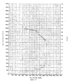
- Fig. 21 is a graph showing discharge at 180°C under 301ohm load of the PMX-HT cell described herein using the cathode current collector material of the present invention.
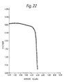
- Fig. 22 is a graph showing discharge at 180°C under 56ohm load of the PMX-HT cell described herein using the cathode current collector material of the present invention.
- The present invention provides a cathode current collector material for lithium solid cathode cells comprising a highly alloyed nickel-containing ferritic stainless steel which provides superior corrosion resistance particularly where elevated temperature storage and performance is required thereby increasing cell longevity relative to other cathode current collector materials. Further, the cathode current collector material of the present invention is less expensive because it does not require costly melting procedures.
- The highly alloyed nickel-containing ferritic stainless steel material for use as a cathode current collector according to the present invention as will be explained further on and formulated in Tables 1 and 3 is currently available under the name SUPERFERRIT (REMANIT 4575) supplied by Thyssen Edelstahlwerke Ag of West Germany. An alternative highly alloyed nickel-containing ferritic stainless steel material for use as a cathode current collector according to the present invention as will be explained further on and formulated in Tables 2 and 4 is currently available under the name AL 29-4-2 (or UNS S44800 in ASTM and ASME specifications) supplied by Allegheny Ludlum Steel Corporation of United States. The cathode current collector material of the present invention generally comprises the elements chromium, molybdenum, nickel, carbon, nitrogen, niobium, zirconium and small amounts of other elements and iron.
- The chromium element of the cathode current collector material confers general corrosion resistance, and resistance to pitting and crevice corrosion to the cathode current collector. The chromium element of the cathode current collector material preferably comprises from about 27.0 percent to about 30.0 percent by weight of the material. For purposes of formulating a cathode current collector material within the scope of the present invention, and for illustration only, not limitation, the element chromium comprises about 28.67 percent by weight of the material.
- The molybdenum element of the cathode current collector material also confers general corrosion resistance, and resistance to pitting and crevice corrosion to the cathode current collector. The molybdenum element of the cathode current collector material comprises from about 2.0 percent to about 4.2 percent by weight of the material. For purposes of formulating a cathode current collector material within the scope of the present invention, and for illustration only, not limitation, the element molybdenum comprises about 2.32 percent by weight of the material.
- The nickel element of the cathode current collector material improves aspects of corrosion resistance in very aggressive media such as reducing acids and under extreme conditions such as those simultaneously promoting stress corrosion cracking and crevice corrosion. Because these conditions often develop in cell environments, it has been discovered that the nickel element in the formulation does not serve as a detriment as suggested in Japanese patent publication no.'s 186467 and 15067. The Japanese publications suggest with regard to cell performance that a cathode current collector material which includes the element nickel reacts negatively to environmental exposure. That is, stress corrosion cracking and crevice corrosion is noted. The nickel element of the cathode current collector material comprises from about 2.0 percent to about 4.5 percent by weight of the material. For purposes of formulating a cathode current collector material within the scope of the present invention, and for illustration only, not limitation, the element nickel comprises about 3.5 percent by weight of the material.
- To achieve very low carbon and nitrogen levels when producing stainless steel, costly melting practices such as vacuum melting must be employed. Relaxing the carbon and nitrogen limit to less than or equal to .045 percent by weight allows the consideration of alternative, less expensive melting techniques which are then reflected in the material cost. The cathode current collector material described herein reflects this advantage. For purposes of formulating a cathode current collector material within the scope of the present invention, and for illustration only, not limitation, the elements carbon plus nitrogen comprises about .029 percent by weight of the material.
- The elements niobium plus zirconium present in the cathode current collector material comprise by weight an amount greater than or equal to about ten times the percent of carbon plus nitrogen present in material. The niobium and zirconium are included in the material to stabilize the carbon and nitrogen. For purposes of formulating a cathode current collector material within the scope of the present invention, and for illustration only, not limitation, the elements niobium plus zirconium comprise about .29 percent by weight of the material.
- Additionally, small amounts of other elements may be present in the cathode current collector material. For purposes of formulating a cathode current collector material within the scope of the present invention, and for illustration only, not limitation, such elements may comprise by weight from about .03 percent to about .18 percent silicon, from about .01 percent to about .42 percent manganese, an amount less than or equal to about .02 percent sulfur, and amount less than or equal to about .025 percent phosphorus and an amount less than or equal to about .15 percent copper.
- The cathode current collector material of the present invention may be fabricated by any of the following techniques: mechanical expansion, chemical machining, etching or milling, electrolytic etching, woven fabric, perforation or foil with vapor deposited bonding layer.
- The following table sets forth a preferred formulation for the cathode current collector material of the present invention wherein the compositional ranges of the various elements are by weight percent of the total material:
- from about 27.0 percent to about 29.0 percent chromium;
from about 2.0 percent to about 3.0 percent molybdenum;
from about 3.0 percent to about 4.5 percent nickel;
the sum of carbon plus nitrogen in an amount less than or equal to .045 percent;
the sum of niobium plus zirconium in an amount of at least ten times the percent of carbon plus nitrogen; small amounts of other elements; and
the remainder being iron. - The following table sets forth another formulation for the cathode current collector material of the present invention wherein the compositional ranges of the various elements are by weight percent of the total material:
- from about 28.0 percent to about 30.0 percent chromium;
from about 3.5 percent to about 4.2 percent molybdenum;
from about 2.0 percent to about 2.5 percent nickel;
the sum of carbon plus nitrogen in an amount less than or equal to .045% per-cent;
small amounts of other elements; and the remainder being iron. - For purposes of formulating a cathode current collector material within the scope of the present invention, and for illustration only, not limitation, the following table sets forth a formulation wherein the composition of the various elements is by weight percent of the total material:
- about 28.67% chromium;
about 2.32% molybdenum;
about 3.52% nickel;
about 0.029% carbon plus nitrogen;
about 0.29% niobium plus zirconium
about 0.31% silicon;
about 0.12% magnesium;
about 0.15% phosphorous; and
the remainder being iron. - For purposes of formulating a cathode current collector material within the scope of the present invention, and for illustration only, not limitation, the following table sets forth another formulation wherein the composition of the various elements is by weight percent of the total material:
- about 29.0% chromium;
about 4.0% molybdenum;
about 2.10% nickel;
about .018% carbon plus nitrogen;
about .06% copper
about .05% magnesium;
about .02% phosphorous;
about .01% sulfur;
about .10% silicon; and
the remainder being iron. - The cathode current collector material of the present invention may be used in lithium solid cathode cells such as lithium fluorinated carbon cells, lithium metal oxide bronze cells, and lithium metal oxide cells. For a detailed description of lithium fluorinated carbon cells which enable use of the cathode current collector material of the present invention reference is made to U.S. Pat. No.'s 3,536,532, 3,700,502 and 4,271,242, the disclosures of which are hereby incorporated by reference.
- An additional lithium flourinated carbon cell compatible for use of the cathode current collector material of the present invention is the C-size cell designated series PMX-HT of Wilson Greatbatch Limited of Clarence, New York. The PMX-HT cell demonstrates an energy density of from about 0.25 watt hrs./cc to about 0.6 watt hrs./cc to 2V under a nominal load of from about 3ohm to 1k ohm and at a temperature of from about -20°C to 180°C. Furthermore, the cell exhibits consistent operational performance over a temperature range of from about -20°C to about 180°C with an operating life at 180°C of about eighteen days, provides an open circuit voltage output of from about 3.0 volts to about 3.5 volts, a nominal current capacity of 4.0AH, a continuous discharge rate to 250mA, and an estimate self discharge rate of less than 2% per year. With reference to Figures 21 and 22, there is shown discharge curves at 180°C and 301ohm and 56ohm loads, respectively, showing the performance of the PMX-HT cell using the cathode current collector material SUPERFERRIT, as described herein. The cell using this material as the cathode current collector is characterized as a 4 ampere hour cell. Further, it has been discovered that this cell using the SUPERFERRIT material as the cathode current collector exhibits better discharge performance at elevated temperatures i.e. 72°C or higher, than a cell using titanium as a cathode current collector.
- For a detailed description of a lithium metal oxide bronze cell compatible to use the cathode current collector material of the present invention reference is made to U.S. Pat. No. 4,391,729, the disclosure of which is hereby incorporated by reference.
- For a detailed description of lithium metal oxide cells compatible to use the cathode current collector material of the present invention, reference is made to U.S. Pat. No. 3,945,848 which discloses the use of cobalt (III) oxide, U.S. Pat. No. 4,158,722 which discloses the use of chromium oxide and U.S. Pat. No. 3,423,242 which discloses the use of vanadium pentoxide, the disclosures of which are hereby incorporated by reference.
- It is understood that the above identified cells are for the purpose of illustration only, and not limitation, and that the present invention is applicable to any cell which enables use of the cathode current collector material of the present invention. The high corrosion resistance of the cathode current collector materials described herein will become more apparent to one skilled in the art with reference to the following examples.
- Evaluation of corrosion behavior of 304 low carbon austenitic stainless steel (304L SS),
Grade 1 titanium and the cathode current collector material of the present invention SUPERFERRIT in lithium silver/vanadium oxide cells was conducted. Fifty-four 7mm thick case negative lithium silver/vanadium oxide cells were built. These cells consisted of three groups relative to the cathode current collector materials used. The titanium group was further subdivided into three groups. The cathode plates of one group were weighed and then humidified at 25°C in a humidity chamber registering 95.5% relative humidity for a duration of 7.25 hours in an attempt to generate a more protective Ti0₂ passivation layer. Following humidification, the cathode plates were placed in a 110°C vacuum oven for 28.5 hours then re-weighed. They were returned to the vacuum oven for another 17.25 hours and again re-weighed. The second group contained cathode plates in which the screens alone were humidified at 98% relative humidity for 30 hours then placed in a 110°C vacuum oven for 20 hours. Both these groups utilized expanded metal screens. The third group consisted of cathode screens which were titanium screens machined and stamped as indicated in Figure 1. Screens were chemically machined from 304 low carbon austenitic stainless steel screens to a thickness of .005 inch. SUPERFERRIT material of .008 inch thickness was obtained from Thyssen Co., Germany. These screens were machined and stamped as depicted in Figure 1. - Six of the above cells, one each from the titanium groups, one containing SUPERFERRIT and two containing 304L SS, were placed at 72°C on open circuit for 1 month. The cathode current collectors were evaluated for corrosion resistance. Anode and separator observations were also conducted.
- Of the above materials tested in the 7mm thick cells stored open circuit at 72°C, SUPERFERRIT exhibited the better response to elevated temperature exposure in lithium silver vanadium oxide. Pitting corrosion was found on the titanium screen exposed to humidity after cathode plate fabrication but not on the pre-humidified titanium screen nor those having no post-cathode pressing humidity treatment. Examination of the SUPERFERRIT cathode current collector revealed no visual evidence of change in surface condition from that of pre-production surface conditions. Cells having 304L SSscreens exhibited variable corrosion performance in the lithium silver vanadium oxide environment.
- To further evaluate the response of the cathode current collector materials of Example I at longer elevated temperature open circuit exposure, seven 7mm thick case negative lithium silver vanadium oxide cells were selected for 3 month storage at 72°C. Three groups sorted according to cathode material used were three
Grade 1 titanium cells: expanded titanium (humidified screen), machined titanium (humidified plate) and machined titanium (as received); two SUPERFERRIT and two 304L SS containing cells. In addition, four of the seven cells, two titanium one SUPERFERRIT and one 304L SS, were submitted for 1k ohm discharge to observe the effect of elevated temperature storage on cell performance. - Anode surfaces of the SUPERFERRIT containing cells were fairly clean and bright. The titanium containing cells exhibited small areas of dark grey to black discoloration at the terminal pin upon which small traces of titanium were detected by energy dispersive X-ray (EDX) after 72°C storage. Of the two 304L SS containing cells, one demonstrated heavy black discoloration of the remainder of the discharged anode particularly near the terminal pin, the anode surface of the other was found to be enveloped in a black layer of material. The separator for the cell also exhibited total black discoloration and EDX detected Cr, Fe and Ni on the discolored surfaces. Open circuit voltages remained stable for all cells except one of the 304L SS containing cells which demonstrated a significant open circuit voltage decrease from 3.27V after burn-in to 2.50V.
- Examination of the cathode screen in the one 304L SS containing cell revealed heavy pitting with extensive corrosion of the screen tab. The degree of pitting in the other cell was much less in comparison to the first. All three titanium cathode current collectors exhibited pits over various face areas with heavy pit concentration near and along the expanded metal and stamped edges. Following 72°C storage the degree and number of pits were similar for all three cells without preference to mode of manufacture or pre-assembly treatment.
- Examination of the SUPERFERRIT cathode current collectors revealed no visual evidence of change in surface condition from that of pre-production surface conditions.
- Potentiodynamic polarization at 37°C was used as a qualitative technique to determine material behavior in the electrolyte when scanned at a rate of .2mV/s from 2.0V to 4.0V using a lithium reference electrode and a platinum wire as an auxiliary electrode. The potentiodynamic polarization procedure as outlined in the ASTM method G5-82 entitled "Standard Reference Method for Making Potentiostatic and Potentiodynamic Polarization Measurements" was followed. An alternate TEFLON test cell with a 35-40 ml capacity was designed for use with this method.
- Polarization characteristics of these materials were obtained by plotting the current response as a function of the applied potential via a log current function versus a potential semi-log chart. Figures 2, 3 and 4 represent polarization plots for titanium, 304L SS and SUPERFERRIT materials respectively. A superimposition of the three plots shown in Figure 5 provided the overall comparison for the metals tested.
- Results obtained suggest that titanium and SUPERFERRIT exhibited comparable behavior in the test medium with measured equilibrium potentials above actual cell open circuit potential. On the other hand, 304L SS maintained an equilibrium potential below this value. Current densities for 304L SS at 3.25V were higher than for the other two metals. This would infer that 304L SS would show a predisposition to corrode at cell operating potentials.
- Cyclic polarization test was used as a qualitative measure for detecting material tendencies toward pitting corrosion in the electrolyte. The cyclic polarization technique used was in accordance with ASTM G61-78 entitled "Standard Practice". A forward scan from 2V to 4V with a reverse scan from 4V to 2V at 1 mV/s was performed. The current response for the applied potential relative to lithium was recorded. The semi-log plots for titanium, 304L SS and SUPERFERRIT are shown in Figures 6, 7 and 8 respectively. The three metals are compared and shown in the superimposition of Figure 9. It was observed that current densities for 304L SS are greater than for titanium and SUPERFERRIT.
- Galvanic corrosion studies were conducted to observe the mutual effects on materials relative to each other in the same environment. The current in the system was monitored over a 5.5 hour period. Initial and final potentials between the materials was recorded. Galvanic corrosion experiments were completed for the test samples versus a silver vanadium oxide (SVO) pellet and versus a molybdenum disk. In addition to the standard test sample, each test disk also had a small molybdenum tab spotwelded to the surface, simulating cathode screen to molybdenum pin attachment, and tested versus a SVO pellet. Figures 10, 11 and 12 show the overall test data of the metal/SVO galvanic couple. Note the higher current densities for 304L SS versus SVO and the similarity in performance of titanium and SUPERFERRIT versus SVO. The initial and final potentials between the metal and SVO were also elevated for 304L SS when compared to the other two test metals.
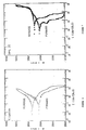
- 7mm thick lithium silver vanadium oxide cells built according to Example I having SUPERFERRIT and titanium as cathode current collector material were discharged at 37°C at 5K to end of life. The discharge curves for the SUPERFERRIT containing cell is shown in Figure 13. The discharge curves for the titanium containing cell is shown in Figure 14. It is observed that cells having SUPERFERRIT and titanium as cathode current collector materials exhibited similar performance characteristics. This suggests that the nickel element of the SUPERFERRIT material does not adversely affect cell performance.
- Micrographs at 600X magnification for cathode current collector materials titanium, SUPERFERRIT and 304L SS before exposure are shown in Figures 15, 16 and 17, respectively. Micrographs at 600X magnification for cathode current collector materials titanium, SUPERFERRIT and 304L SS after a three month exposure at 72°C are shown in Figures 18, 19, and 20 respectively. The results indicate that 304L SS exhibited massive corrosion, the titanium exhibited pitting and the SUPERFERRIT exhibited no change. This indicates that SUPERFERRIT exhibits superior corrosion resistance compared to the other cathode current collector materials. Furthermore, it has been discovered that the nickel element in the formulation does not serve as a detriment with respect to corrosion as suggested in Japanese patent publication no.'s 186467 and 15067.
Claims (10)
- A cathode current collector for a solid cathode electrochemical cell, said collector being formed of material comprising a highly alloyed nickel-containing ferritic stainless steel, said cathode current collector providing high corrosion resistance particularly where elevated temperature storage and performance is required thereby increasing cell longevity.
- The cathode current collector of claim 1, wherein said highly alloyed nickel-containing ferritic stainless steel comprises by weight:
from about 27.0 percent to about 29.0 percent chromium;
from about 2.0 percent to about 3.0 percent molybdenum;
from about 3.0 percent to about 4.5 percent nickel;
the sum of carbon plus nitrogen in an amount less than or equal to .045 percent;
the sum of niobium plus zirconium in an amount of at least ten times the percent of carbon plus nitrogen; and
the remainder being iron. - The cathode current collector of claim 1, wherein said highly alloyed nickel-containing ferritic stainless steel comprises by weight:
from about 28.0 percent to about 30.0 percent chromium;
from about 3.5 percent to about 4.2 percent molybdenum;
from about 2.0 percent to about 2.5 percent nickel;
the sum of carbon plus nitrogen in an amount less than or equal to .025 percent; and
the remainder being iron. - The cathode current collector of claim 2 or claim 3 wherein said highly alloyed nickel-containing ferritic stainless steel further comprises by weight small amounts of trace elements.
- The cathode current collector of claim 4, wherein said trace elements are selected from the group consisting of copper, magnesium, phosphorous, sulfur and silicon.
- The cathode current collector of any one of claims 1 to 5 wherein said solid cathode is selected from a metal oxide, metal oxide bronze and fluorinated carbon.
- The cathode current collector of claim 6 wherein said metal oxide bronze is silver vanadium oxide.
- The cathode current collector of claim 6 wherein said fluorinated carbon is polycarbon monofluoride (CFx) wherein x ranges from about 0.5 to about 1.2.
- The cathode current collector of any one of claims 1 to 8, in the form of a sheet, or a screen.
- An electrochemical cell comprising an anode, a solid cathode material used in conjunction with a cathode current collector, and an ionically conductive electrolyte solution operatively associated with said anode and cathode, characterised in that said cathode current collector comprises a highly alloyed nickel-containing ferritic stainless steel material, said material providing high corrosion resistance particularly where elevated temperature storage and performance is required thereby increasing cell longevity.
Applications Claiming Priority (2)
| Application Number | Priority Date | Filing Date | Title |
|---|---|---|---|
| US07/475,261 US5114810A (en) | 1990-02-05 | 1990-02-05 | Cathode current collector material for solid cathode cell |
| US475261 | 1990-02-05 |
Publications (3)
| Publication Number | Publication Date |
|---|---|
| EP0441583A2 true EP0441583A2 (en) | 1991-08-14 |
| EP0441583A3 EP0441583A3 (en) | 1992-11-04 |
| EP0441583B1 EP0441583B1 (en) | 1996-05-08 |
Family
ID=23886840
Family Applications (1)
| Application Number | Title | Priority Date | Filing Date |
|---|---|---|---|
| EP91300907A Expired - Lifetime EP0441583B1 (en) | 1990-02-05 | 1991-02-05 | Cathode current collector material for solid cathode cell |
Country Status (4)
| Country | Link |
|---|---|
| US (1) | US5114810A (en) |
| EP (1) | EP0441583B1 (en) |
| AT (1) | ATE137888T1 (en) |
| DE (1) | DE69119256T2 (en) |
Cited By (3)
| Publication number | Priority date | Publication date | Assignee | Title |
|---|---|---|---|---|
| EP0599654A1 (en) * | 1992-11-26 | 1994-06-01 | Seiko Electronic Components Ltd. | Non-aqueous electrolyte electrochemical cell |
| EP1670086A1 (en) * | 2004-12-08 | 2006-06-14 | Wilson Greatbatch Technologies, Inc. | Nickel-based alloys as positive electrode current collectors in electrochemical cells containing nonaqueous electrolytes |
| CN102392189A (en) * | 2011-11-16 | 2012-03-28 | 钢铁研究总院 | High-Cr ferrite stainless steel and manufacturing method thereof |
Families Citing this family (14)
| Publication number | Priority date | Publication date | Assignee | Title |
|---|---|---|---|---|
| US5458997A (en) | 1994-08-19 | 1995-10-17 | Medtronic, Inc. | Rebalancing of lithium/silver vandium oxide (Li/SVO) cells for improved performance |
| US5643690A (en) * | 1994-11-11 | 1997-07-01 | Kabushiki Kaisha Toshiba | Molten carbonate fuel cell |
| US5811206A (en) * | 1997-10-31 | 1998-09-22 | Medtronic, Inc. | Feedthrough pin insulator, assembly and method for electrochemical cell |
| US6445948B1 (en) | 1998-04-03 | 2002-09-03 | Medtronic, Inc. | Implantable medical device having a substantially flat battery |
| US6459566B1 (en) | 1998-06-24 | 2002-10-01 | Medtronic, Inc. | Implantable medical device having flat electrolytic capacitor with laser welded cover |
| US6306544B1 (en) | 1999-02-25 | 2001-10-23 | Wilson Greatbatch Ltd. | Cobalt-based alloys as positive electrode current collectors in nonaqueous electrochemical cells |
| US6350543B2 (en) | 1999-12-29 | 2002-02-26 | Kimberly-Clark Worldwide, Inc. | Manganese-rich quaternary metal oxide materials as cathodes for lithium-ion and lithium-ion polymer batteries |
| US7314685B2 (en) * | 2001-07-30 | 2008-01-01 | Greatbatch Ltd. | Oxidized titanium as a cathodic current collector |
| US6671552B2 (en) | 2001-10-02 | 2003-12-30 | Medtronic, Inc. | System and method for determining remaining battery life for an implantable medical device |
| US6804557B1 (en) | 2001-10-11 | 2004-10-12 | Pacesetter, Inc. | Battery monitoring system for an implantable medical device |
| GB0601813D0 (en) * | 2006-01-30 | 2006-03-08 | Ceres Power Ltd | Fuel cell |
| US9985294B2 (en) | 2015-05-29 | 2018-05-29 | Pacesetter, Inc. | High energy density and high rate Li battery |
| US10985407B2 (en) | 2017-11-21 | 2021-04-20 | Samsung Electronics Co., Ltd. | All-solid-state secondary battery including anode active material alloyable with lithium and method of charging the same |
| US11824155B2 (en) | 2019-05-21 | 2023-11-21 | Samsung Electronics Co., Ltd. | All-solid lithium secondary battery and method of charging the same |
Citations (5)
| Publication number | Priority date | Publication date | Assignee | Title |
|---|---|---|---|---|
| FR2196850A1 (en) * | 1972-08-04 | 1974-03-22 | Du Pont | Composite lithium anode - with stainless steel aluminium or zinc support |
| EP0118614A2 (en) * | 1982-12-15 | 1984-09-19 | Hitachi Maxell Ltd. | Alkaline cell |
| EP0245705A1 (en) * | 1986-05-06 | 1987-11-19 | Asea Brown Boveri Aktiengesellschaft | Electrochemical storage cell |
| FR2611405A1 (en) * | 1987-02-25 | 1988-09-02 | Bridgestone Corp | ELECTRICAL BATTERY WITH COLLECTOR ENROBE |
| DE3918963A1 (en) * | 1988-06-20 | 1989-12-21 | Bridgestone Corp | Secondary cell with non-aqueous, liquid electrolyte |
Family Cites Families (6)
| Publication number | Priority date | Publication date | Assignee | Title |
|---|---|---|---|---|
| NL6504262A (en) * | 1965-04-03 | 1966-10-04 | ||
| FR2260876B1 (en) * | 1974-02-08 | 1978-06-16 | Accumulateurs Fixes | |
| JPS549730A (en) * | 1977-06-24 | 1979-01-24 | Matsushita Electric Ind Co Ltd | Active material on positive electrode of battery |
| DE2829031C3 (en) * | 1977-07-07 | 1982-05-19 | Matsushita Electric Industrial Co., Ltd., Kadoma, Osaka | Galvanic cell with a solid electrolyte made of lithium iodide |
| DE3635257A1 (en) * | 1985-10-17 | 1987-04-23 | Bridgestone Corp | GALVANIC ELEMENT |
| US4818483A (en) * | 1986-12-29 | 1989-04-04 | Carondelet Foundry Company | Alloy resistant to seawater and corrosive process fluids |
-
1990
- 1990-02-05 US US07/475,261 patent/US5114810A/en not_active Expired - Lifetime
-
1991
- 1991-02-05 AT AT91300907T patent/ATE137888T1/en not_active IP Right Cessation
- 1991-02-05 EP EP91300907A patent/EP0441583B1/en not_active Expired - Lifetime
- 1991-02-05 DE DE69119256T patent/DE69119256T2/en not_active Expired - Fee Related
Patent Citations (5)
| Publication number | Priority date | Publication date | Assignee | Title |
|---|---|---|---|---|
| FR2196850A1 (en) * | 1972-08-04 | 1974-03-22 | Du Pont | Composite lithium anode - with stainless steel aluminium or zinc support |
| EP0118614A2 (en) * | 1982-12-15 | 1984-09-19 | Hitachi Maxell Ltd. | Alkaline cell |
| EP0245705A1 (en) * | 1986-05-06 | 1987-11-19 | Asea Brown Boveri Aktiengesellschaft | Electrochemical storage cell |
| FR2611405A1 (en) * | 1987-02-25 | 1988-09-02 | Bridgestone Corp | ELECTRICAL BATTERY WITH COLLECTOR ENROBE |
| DE3918963A1 (en) * | 1988-06-20 | 1989-12-21 | Bridgestone Corp | Secondary cell with non-aqueous, liquid electrolyte |
Cited By (6)
| Publication number | Priority date | Publication date | Assignee | Title |
|---|---|---|---|---|
| EP0599654A1 (en) * | 1992-11-26 | 1994-06-01 | Seiko Electronic Components Ltd. | Non-aqueous electrolyte electrochemical cell |
| US5478670A (en) * | 1992-11-26 | 1995-12-26 | Seiko Electronic Components, Ltd. | Non-aqueous electrolyte electrochemical cell comprising high Ni austenitic stainless steel positive electrode case |
| CN1132256C (en) * | 1992-11-26 | 2003-12-24 | 精工电子部品株式会社 | Non-aqueous electrolyte electrochemical cell |
| EP1670086A1 (en) * | 2004-12-08 | 2006-06-14 | Wilson Greatbatch Technologies, Inc. | Nickel-based alloys as positive electrode current collectors in electrochemical cells containing nonaqueous electrolytes |
| CN102392189A (en) * | 2011-11-16 | 2012-03-28 | 钢铁研究总院 | High-Cr ferrite stainless steel and manufacturing method thereof |
| CN102392189B (en) * | 2011-11-16 | 2013-05-29 | 钢铁研究总院 | High-Cr ferrite stainless steel and manufacturing method thereof |
Also Published As
| Publication number | Publication date |
|---|---|
| DE69119256T2 (en) | 1996-09-19 |
| DE69119256D1 (en) | 1996-06-13 |
| EP0441583B1 (en) | 1996-05-08 |
| ATE137888T1 (en) | 1996-05-15 |
| EP0441583A3 (en) | 1992-11-04 |
| US5114810A (en) | 1992-05-19 |
Similar Documents
| Publication | Publication Date | Title |
|---|---|---|
| EP0441583B1 (en) | Cathode current collector material for solid cathode cell | |
| Zhu et al. | Opportunity of metallic interconnects for solid oxide fuel cells: a status on contact resistance | |
| US7981561B2 (en) | Interconnects for solid oxide fuel cells and ferritic stainless steels adapted for use with solid oxide fuel cells | |
| Geng et al. | Evaluation of Haynes 242 alloy as SOFC interconnect material | |
| CA2604593C (en) | Interconnects for solid oxide fuel cells and ferritic stainless steels adapted for use with solid oxide fuel cells | |
| KR100887430B1 (en) | Current collector for SOFC fuel cells | |
| US20060286433A1 (en) | Interconnects for solid oxide fuel cells and ferritic stainless steels adapted for use with solid oxide fuel cells | |
| CN101950807B (en) | Low-cost manganese-stabilized austenitic stainless steel alloys, bipolar plates comprising the alloys, and fuel cell systems comprising the bipolar plates | |
| JP2004520479A (en) | High temperature material | |
| US20060285993A1 (en) | Interconnects for solid oxide fuel cells and ferritic stainless steels adapted for use with solid oxide fuel cells | |
| KR20070012495A (en) | Heat-resistant steel | |
| Park et al. | Performance and long-term stability of Ti metal and stainless steels as a metal bipolar plate for a direct methanol fuel cell | |
| Frangini | Corrosion of metallic stack components in molten carbonates: critical issues and recent findings | |
| Zhu et al. | Comparison of electrochemical and surface characterisation methods for investigation of corrosion of bipolar plate materials in molten carbonate fuel cell: Part I. Electrochemical study | |
| Jian et al. | Oxidation of Haynes 230 alloy in reduced temperature solid oxide fuel cell environments | |
| Wang et al. | An investigation on metallic bipolar plate corrosion in simulated anode and cathode environments of PEM fuel cells using potential-pH diagrams | |
| KR20080109148A (en) | Stainless steel having excellent corrosion resistance and electric conductivity and bipolar plate made of the same | |
| EP3465808B1 (en) | Mixed metal oxide compounds and electrocatalytic compositions, devices and processes using the same | |
| JPH04358044A (en) | High corrosion resistant steel sheet for molten carbonate type fuel cell separator | |
| EP1670086B1 (en) | Nickel-based alloys as positive electrode current collectors in electrochemical cells containing nonaqueous electrolytes | |
| Schoeler et al. | Corrosion behavior of coated steels and Mn‐and Co‐alloyed steels for separator materials on the cathode side in molten carbonate fuel cells | |
| KR101027222B1 (en) | OAE/Co Coating for Planar Solid Oxide Fuel Cell Interconnects | |
| WO2021019849A1 (en) | Austenitic stainless steel sheet for fuel cell separator substrate | |
| Geng et al. | Investigation on haynes 242 alloy as SOFC interconnect in simulated anode environment | |
| Shemet et al. | Metallic materials in solid oxide fuel cells |
Legal Events
| Date | Code | Title | Description |
|---|---|---|---|
| PUAI | Public reference made under article 153(3) epc to a published international application that has entered the european phase |
Free format text: ORIGINAL CODE: 0009012 |
|
| AK | Designated contracting states |
Kind code of ref document: A2 Designated state(s): AT BE CH DE DK ES FR GB GR IT LI LU NL SE |
|
| PUAL | Search report despatched |
Free format text: ORIGINAL CODE: 0009013 |
|
| AK | Designated contracting states |
Kind code of ref document: A3 Designated state(s): AT BE CH DE DK ES FR GB GR IT LI LU NL SE |
|
| 17P | Request for examination filed |
Effective date: 19930419 |
|
| 17Q | First examination report despatched |
Effective date: 19940422 |
|
| GRAH | Despatch of communication of intention to grant a patent |
Free format text: ORIGINAL CODE: EPIDOS IGRA |
|
| GRAA | (expected) grant |
Free format text: ORIGINAL CODE: 0009210 |
|
| AK | Designated contracting states |
Kind code of ref document: B1 Designated state(s): AT BE CH DE DK ES FR GB GR IT LI LU NL SE |
|
| PG25 | Lapsed in a contracting state [announced via postgrant information from national office to epo] |
Ref country code: IT Free format text: LAPSE BECAUSE OF FAILURE TO SUBMIT A TRANSLATION OF THE DESCRIPTION OR TO PAY THE FEE WITHIN THE PRESCRIBED TIME-LIMIT;WARNING: LAPSES OF ITALIAN PATENTS WITH EFFECTIVE DATE BEFORE 2007 MAY HAVE OCCURRED AT ANY TIME BEFORE 2007. THE CORRECT EFFECTIVE DATE MAY BE DIFFERENT FROM THE ONE RECORDED. Effective date: 19960508 Ref country code: ES Free format text: THE PATENT HAS BEEN ANNULLED BY A DECISION OF A NATIONAL AUTHORITY Effective date: 19960508 Ref country code: LI Effective date: 19960508 Ref country code: GR Free format text: LAPSE BECAUSE OF FAILURE TO SUBMIT A TRANSLATION OF THE DESCRIPTION OR TO PAY THE FEE WITHIN THE PRESCRIBED TIME-LIMIT Effective date: 19960508 Ref country code: BE Effective date: 19960508 Ref country code: AT Effective date: 19960508 Ref country code: CH Effective date: 19960508 Ref country code: DK Effective date: 19960508 |
|
| REF | Corresponds to: |
Ref document number: 137888 Country of ref document: AT Date of ref document: 19960515 Kind code of ref document: T |
|
| REF | Corresponds to: |
Ref document number: 69119256 Country of ref document: DE Date of ref document: 19960613 |
|
| ET | Fr: translation filed | ||
| REG | Reference to a national code |
Ref country code: CH Ref legal event code: PL |
|
| PG25 | Lapsed in a contracting state [announced via postgrant information from national office to epo] |
Ref country code: GB Effective date: 19970205 |
|
| PG25 | Lapsed in a contracting state [announced via postgrant information from national office to epo] |
Ref country code: SE Effective date: 19970206 |
|
| PG25 | Lapsed in a contracting state [announced via postgrant information from national office to epo] |
Ref country code: LU Free format text: LAPSE BECAUSE OF NON-PAYMENT OF DUE FEES Effective date: 19970228 |
|
| PLBE | No opposition filed within time limit |
Free format text: ORIGINAL CODE: 0009261 |
|
| STAA | Information on the status of an ep patent application or granted ep patent |
Free format text: STATUS: NO OPPOSITION FILED WITHIN TIME LIMIT |
|
| 26N | No opposition filed | ||
| PG25 | Lapsed in a contracting state [announced via postgrant information from national office to epo] |
Ref country code: NL Effective date: 19970901 |
|
| GBPC | Gb: european patent ceased through non-payment of renewal fee |
Effective date: 19970205 |
|
| PG25 | Lapsed in a contracting state [announced via postgrant information from national office to epo] |
Ref country code: FR Effective date: 19971030 |
|
| PG25 | Lapsed in a contracting state [announced via postgrant information from national office to epo] |
Ref country code: DE Effective date: 19971101 |
|
| EUG | Se: european patent has lapsed |
Ref document number: 91300907.2 |
|
| NLV4 | Nl: lapsed or anulled due to non-payment of the annual fee |
Effective date: 19970901 |
|
| REG | Reference to a national code |
Ref country code: FR Ref legal event code: ST |