EP0440999A2 - Improved check-weighing machine - Google Patents
Improved check-weighing machine Download PDFInfo
- Publication number
- EP0440999A2 EP0440999A2 EP90203317A EP90203317A EP0440999A2 EP 0440999 A2 EP0440999 A2 EP 0440999A2 EP 90203317 A EP90203317 A EP 90203317A EP 90203317 A EP90203317 A EP 90203317A EP 0440999 A2 EP0440999 A2 EP 0440999A2
- Authority
- EP
- European Patent Office
- Prior art keywords
- shaft
- conveyor
- motor unit
- geared motor
- drive roller
- Prior art date
- Legal status (The legal status is an assumption and is not a legal conclusion. Google has not performed a legal analysis and makes no representation as to the accuracy of the status listed.)
- Granted
Links
- 238000005303 weighing Methods 0.000 title claims description 26
- 230000033001 locomotion Effects 0.000 claims abstract description 24
- 230000008878 coupling Effects 0.000 claims description 33
- 238000010168 coupling process Methods 0.000 claims description 33
- 238000005859 coupling reaction Methods 0.000 claims description 33
- 229920001971 elastomer Polymers 0.000 claims description 5
- 239000002184 metal Substances 0.000 claims description 5
- 239000000806 elastomer Substances 0.000 claims description 4
- 230000009347 mechanical transmission Effects 0.000 claims description 3
- 238000011144 upstream manufacturing Methods 0.000 description 9
- 230000005540 biological transmission Effects 0.000 description 8
- 230000004044 response Effects 0.000 description 5
- 238000010276 construction Methods 0.000 description 4
- 238000005259 measurement Methods 0.000 description 3
- 230000008859 change Effects 0.000 description 1
- 238000013016 damping Methods 0.000 description 1
- 230000006872 improvement Effects 0.000 description 1
- 230000009467 reduction Effects 0.000 description 1
Images


Classifications
-
- G—PHYSICS
- G01—MEASURING; TESTING
- G01G—WEIGHING
- G01G11/00—Apparatus for weighing a continuous stream of material during flow; Conveyor belt weighers
- G01G11/003—Details; specially adapted accessories
Definitions
- This invention relates to a machine for checking the weight of objects in continuous movement; these machines are known generally as check-weighing machines.
- Such machines comprise a belt conveyor which totally acts on a balance arranged to measure the weight of objects in transit on said belt conveyor.
- This conveyor is composed essentially of two rollers, one of which is a drive roller, an endless flexible belt stretched between the two rollers, a fixed support structure comprising a fixed slide table for the upper branch of the belt, and a geared motor unit which drives the drive roller for the belt.
- the weight of all these members acts on the balance, the upper branch of the belt basically defining the weighing plate.
- Two further belt conveyors are generally provided upstream and downstream of said weighing belt respectively; these conveyors do not act on the balance and have a linear speed substantially equal to that of the weighing belt.
- the purpose of the upstream belt conveyor is to withdraw the objects from an upstream conveying line and to lead them onto the intermediate weighing belt; its presence is necessary to obtain correct spacing of the objects and to give them the same speed as the weighing belt to prevent them undergoing dynamic influence; any speed variation between the weighing belt and the upstream belt would in fact harm the weighing accuracy.
- downstream conveyor The purpose of the downstream conveyor is merely to lead the weighed objects away and possibly to support any devices for removing or expelling those objects which have been found to be outside the weight tolerance. Its presence is relatively less necessary than the upstream belt.
- Measurement precision is extremely important in these machines, and the more so the smaller the weight of the objects. Consequently with the passing of time the construction of these machines has been continuously improved by placing special emphasis on reducing as much as possible the influence of the weighing belt on the balance measurements; in this respect this represents a relatively high tare value, and it has therefore been sought to reduce its weight and in particular the weight of the geared motor unit to the minimum possible values, and in addition it has been sought to prevent vibration and dynamic influence as much as possible.
- the accuracy of a balance is proportional to the quality of its construction and to the size of the relative range of measurement, while the weighing response depends on the inertia of the masses in play.
- the balance is loaded by a conveyor and the relative geared motor unit which together weight some hundreds of grams.
- the balance may thus be subjected for example to a tare of 1000 g (the weight of the conveyor belt plus geared motor unit) plus 20 g representing the weight of the object.
- the error in absolute terms has to be limited to within two tenths of a gram in a total weight of more than 1 kg.
- the accuracy must thus be just a few parts in 10,000.
- the object of the present invention is to eliminate or at least reduce said drawbacks, by improving weighing accuracy and response.
- the geared motor unit which provides rotary motion to the roller driving the conveyor which acts on the balance is located at a distance from and to the side of the conveyor and is supported with the axis of its drive shaft in a fixed position substantially parallel to the axis of said drive roller, by a fixed structure which is not suspended and therefore does not act on the balance.
- This is made possible by the use of particular mechanical members, also forming part of the invention, which are arranged to axially transmit motion from the shaft of the geared motor unit to the shaft of the drive roller, while allowing relative movement between the axis of the geared motor unit drive shaft and the axis of said drive roller shaft, without disturbing weighing.
- homokinetic couplings have the common characteristic of consisting of at least three parts, two of which are rigid with the shafts and the third is arranged such that it always forms equal angles with the axes of the two shafts.
- these mechanical couplings satisfy the homokinetic condition valid for double universal joints in which the intermediate shaft is reduced to a small-dimension mechanical element.
- Homokinetic mechanical couplings have a weight and cost incompatible with their application to precision balances of the type under discussion.
- a further essential characteristic is that all the conveyors run at exactly the same speed, making it obligatory to use direct current motors and a common electronic control circuit.
- the machine of the invention therefore enables the conveyor acting on the balance to be lightened by the weight of the geared motor unit, and as this represents most of the weight of the entire system, the tare of the balance is considerably reduced. Consequently there is an improved system response, ie the weighing speed is increased, and the weighing accuracy is improved.
- a greater and more adequate power can be used to drive the belt conveyor than in the case of known machines; in this respect these have generally inadequate power in order to limit the weight of the geared motor unit.
- the geared motor unit does not act on the balance, it is possible to also motorize the drive rollers for the belts upstream or downstream of the weighing belt with mechanical transmission members from the same geared motor unit as motion source, so mechanically ensuring that the three conveyors maintain the same linear speed, as is required.
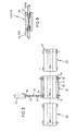
- Figure 1 is a schematic vertical front elevation of the machine of the invention.
- Figure 2 is a schematic section on the plane II-II of Figure 1.
- Figure 3 is a schematic top plan view of a first preferred embodiment of the machine of the preceding figures.
- Figure 4 is a schematic top plan view of a second preferred embodiment of the machine.
- Figure 5 shows an embodiment of the coupling applied to the machine.
- Figure 6 shows a further embodiment of the coupling applied to the machine.
- the machine of the invention comprises a belt conveyor 10 consisting of an endless flexible belt extending between a drive roller 12 and a deviation roller 13, and a support structure 16, with which the respective shafts 14 and 15 of the rollers 12 and 13 are engaged.
- a rigid plate 17 for supporting the upper branch of the belt 11 is also fixed to the structure 16.
- the entire structure 16 and the elements supported by it act with their own weight on a balance 4 of known type, arranged to measure the weight of the objects conveyed by the conveyor 10.
- a geared motor unit 40 is provided to provide the required rotary movement to the drive roller 12 of the conveyor 10, said geared motor unit 40 being supported by a structure 41 which rests directly on the structure 5 and therefore does not act on the balance 4.
- the geared motor unit 40 is positioned to the side of and spaced apart from the roller 12 and lies substantially on the same axis as this roller.
- Motion is transmitted from the geared motor unit 40 to the roller 12 by the provision of mechanical members for axial motion transmission, of the type which allows slight relative movement between the axis of the shaft 44 of the geared motor unit 40 and the axis of the shaft 14 of the roller 12.
- first elastic coupling 42 connected to the shaft 44 of the geared motor unit 40
- second elastic coupling 43 connected to the shaft 14 of the drive roller 12
- an intermediate transmission shaft 45 the ends of which are connected to the coupling 42 and to the coupling 43 respectively.
- a single coupling 42 or 43 can be provided directly connecting the shafts 14 and 44 together, without the intermediate shaft 45.
- a part of the weight of said transmission members ie the couplings 42 and 43 and the shaft 45, or the coupling 42 or 43 alone
- the shaft 44 of the geared motor unit supports the shaft 44 of the geared motor unit and therefore does not act on the balance 4; the rest of the weight together with the weight of the shaft 14 acts on the balance.
- the weight proportion acting on the balance does not change, whether the members are fixed or rotating, and whether or not there are objects 2 on the balance.
- the invention enables the aforesaid advantages to be attained, ie improved weighing response and accuracy.
- a motor having a power more adequate for the machine requirements can be used, ie a larger and heavier motor.
- a coupling 42 or 43 can be used consisting of a cylindrical elastomer element 46 provided with an axial bore; the ends of the shafts 44 and 45, or 45 and 14, connected to this coupling are forced into the ends of the axial bore in the element 46, and to improve torsional rigidity the ends of these shafts can be provided with slight longitudinal projections 47.
- This coupling is illustrated in Figure 5.
- a further suitable type of coupling is of metal construction and is able to transmit greater torques.
- This coupling is known commercially by the name HELICAL and comprises two cylindrical bored end pieces 48 connected together by a helix 49 formed from a strip of small axial dimension but much larger radial dimension; the ends of the shafts 44 and 45, or 45 and 14, are inserted into the bores of the respective pieces 48 and are fixed rigidly thereto.
- the conveyors 20 and 30 are generally driven by geared motor units connected rigidly to them, a complex and costly system also being required to make the linear speeds of the three belts exactly equal.
- geared motor unit for each conveyor 20 and 30 there are usually provided for this purpose a tachometer dynamo and an electronic speed control device; in addition a common electronic device is provided for equalizing the speeds of the three belts 10, 20 and 30.
- the invention enables the system to be considerably simplified, by means of the preferred embodiment shown in Figure 4.
- a single geared motor unit 40 of adequate power is arranged to provide the required rotary motion both to the drive roller 12 of the conveyor 10 and to the drive rollers 22 and 32 of the upstream and downstream conveyors, said geared motor unit 40 being supported by a structure which rests directly on the structure 5 and therefore does not act on the balance 4.
- the geared motor unit 40 is positioned to the side of and spaced from the roller 12 and is substantially coaxial thereto.
- the shaft 44 of the geared motor unit 40 transmits motion directly to other shafts 29 and 31 supported by said structure 41 and parallel to the shaft 44.
- One pulley 28 is fixed on the shaft 44 and the other on the shaft 29, one pulley 38 being also fixed on the shaft 44 and the other on the shaft 39.
- the shafts 29 and 39 are axially connected by suitable couplings 25 and 35 to the shaft 24 of the drive roller 22 for the conveyor 20 and to the shaft 34 of the drive roller 32 for the conveyor 30 respectively.
- the shafts 29 and 39 are arranged coaxially to the shafts 24 and 34 respectively.
- the shafts 29 and 24 can also be defined by a single uninterrupted shaft as can the shafts 39 and 34.
Landscapes
- General Physics & Mathematics (AREA)
- Physics & Mathematics (AREA)
- Structure Of Belt Conveyors (AREA)
- Macromolecular Compounds Obtained By Forming Nitrogen-Containing Linkages In General (AREA)
- Replacing, Conveying, And Pick-Finding For Filamentary Materials (AREA)
- Combined Means For Separation Of Solids (AREA)
- Error Detection And Correction (AREA)
- Preparation Of Compounds By Using Micro-Organisms (AREA)
- Sorting Of Articles (AREA)
- Processing And Handling Of Plastics And Other Materials For Molding In General (AREA)
- Injection Moulding Of Plastics Or The Like (AREA)
- Cereal-Derived Products (AREA)
- Devices For Conveying Motion By Means Of Endless Flexible Members (AREA)
Abstract
Description
- This invention relates to a machine for checking the weight of objects in continuous movement; these machines are known generally as check-weighing machines.
- Such machines comprise a belt conveyor which totally acts on a balance arranged to measure the weight of objects in transit on said belt conveyor. This conveyor is composed essentially of two rollers, one of which is a drive roller, an endless flexible belt stretched between the two rollers, a fixed support structure comprising a fixed slide table for the upper branch of the belt, and a geared motor unit which drives the drive roller for the belt. The weight of all these members acts on the balance, the upper branch of the belt basically defining the weighing plate.
- Two further belt conveyors are generally provided upstream and downstream of said weighing belt respectively; these conveyors do not act on the balance and have a linear speed substantially equal to that of the weighing belt.
- The purpose of the upstream belt conveyor is to withdraw the objects from an upstream conveying line and to lead them onto the intermediate weighing belt; its presence is necessary to obtain correct spacing of the objects and to give them the same speed as the weighing belt to prevent them undergoing dynamic influence; any speed variation between the weighing belt and the upstream belt would in fact harm the weighing accuracy.
- The purpose of the downstream conveyor is merely to lead the weighed objects away and possibly to support any devices for removing or expelling those objects which have been found to be outside the weight tolerance. Its presence is relatively less necessary than the upstream belt.
- Measurement precision is extremely important in these machines, and the more so the smaller the weight of the objects. Consequently with the passing of time the construction of these machines has been continuously improved by placing special emphasis on reducing as much as possible the influence of the weighing belt on the balance measurements; in this respect this represents a relatively high tare value, and it has therefore been sought to reduce its weight and in particular the weight of the geared motor unit to the minimum possible values, and in addition it has been sought to prevent vibration and dynamic influence as much as possible.
- Although known machines operate satisfactorily they are however susceptible to improvement with regard to weighing accuracy and response.
- As is well known, the accuracy of a balance is proportional to the quality of its construction and to the size of the relative range of measurement, while the weighing response depends on the inertia of the masses in play.
- In known machines, by far the largest weight acting on the balance is that of the geared motor unit which drives the weighing conveyor; in addition both the motor and the reduction gear are sources of vibration which are disturbing because of their frequency and even more so because of their dynamic intensity, in that they originate from considerable masses.
- With regard to accuracy, it will be apparent that in checking objects weighing just a few grams the balance is loaded by a conveyor and the relative geared motor unit which together weight some hundreds of grams. The balance may thus be subjected for example to a tare of 1000 g (the weight of the conveyor belt plus geared motor unit) plus 20 g representing the weight of the object. In seeking to obtain an accuracy of at least 1%, the error in absolute terms has to be limited to within two tenths of a gram in a total weight of more than 1 kg. Thus in relative terms the accuracy must thus be just a few parts in 10,000.
- The object of the present invention is to eliminate or at least reduce said drawbacks, by improving weighing accuracy and response.
- Said object is attained by the machine according to the invention in that the geared motor unit which provides rotary motion to the roller driving the conveyor which acts on the balance is located at a distance from and to the side of the conveyor and is supported with the axis of its drive shaft in a fixed position substantially parallel to the axis of said drive roller, by a fixed structure which is not suspended and therefore does not act on the balance. This is made possible by the use of particular mechanical members, also forming part of the invention, which are arranged to axially transmit motion from the shaft of the geared motor unit to the shaft of the drive roller, while allowing relative movement between the axis of the geared motor unit drive shaft and the axis of said drive roller shaft, without disturbing weighing.
- In this respect, all the attempts made up to the present time to improve the weighing conditions have been limited to reducing the suspended masses acting on the balance, as there is a strong and understandable prejudice against positioning the motor between the unsuspended masses with a mechanical transmission between the motor shaft and the shaft of the belt drive roller.
- This prejudice derives from the known impossibility of providing a coupling between two parallel but non-aligned shafts which is of simple and therefore light construction, and at the same time perfectly homokinetic.
- In this respect, homokinetic couplings have the common characteristic of consisting of at least three parts, two of which are rigid with the shafts and the third is arranged such that it always forms equal angles with the axes of the two shafts.
- Basically, these mechanical couplings satisfy the homokinetic condition valid for double universal joints in which the intermediate shaft is reduced to a small-dimension mechanical element.
- Homokinetic mechanical couplings have a weight and cost incompatible with their application to precision balances of the type under discussion.
- In addition they are not free of vibration, this being a further important characteristic which advises against their use in conveyor belt balances, in that they compromise their accuracy
- Again, the until now essential requirement of mounting the weighing conveyor drive motor rigid therewith means that a perfect system must be provided for controlling the speed of this motor in relation to the speed of the motors which drive the conveyors upstream and downstream of the weighing conveyor
- In this respect a further essential characteristic is that all the conveyors run at exactly the same speed, making it obligatory to use direct current motors and a common electronic control circuit.
- The aforesaid problems are solved according to the invention by using a coupling of an elastomer such as rubber, or a deformable metal coupling, which within the range of misalignments between the shafts found in this particular sector, and which are of the order of some hundredths of a centimetre, has proved particularly suitable for the purpose.
- The combined flexibility, lightness and plasticity characterisics of an elastomer make totally sufficient motion transmission possible, with simultaneous vibration damping, so leading to improved results.
- Similar results are obtained by the particular configuration of a deformable metal coupling.
- The machine of the invention therefore enables the conveyor acting on the balance to be lightened by the weight of the geared motor unit, and as this represents most of the weight of the entire system, the tare of the balance is considerably reduced. Consequently there is an improved system response, ie the weighing speed is increased, and the weighing accuracy is improved. In addition, a greater and more adequate power can be used to drive the belt conveyor than in the case of known machines; in this respect these have generally inadequate power in order to limit the weight of the geared motor unit.
- In addition, as the geared motor unit does not act on the balance, it is possible to also motorize the drive rollers for the belts upstream or downstream of the weighing belt with mechanical transmission members from the same geared motor unit as motion source, so mechanically ensuring that the three conveyors maintain the same linear speed, as is required.
- The invention is described in detail hereinafter with reference to the accompanying figures, which show a preferred but not exclusive embodiment thereof.
- Figure 1 is a schematic vertical front elevation of the machine of the invention.
- Figure 2 is a schematic section on the plane II-II of Figure 1.
- Figure 3 is a schematic top plan view of a first preferred embodiment of the machine of the preceding figures.
- Figure 4 is a schematic top plan view of a second preferred embodiment of the machine.
- Figure 5 shows an embodiment of the coupling applied to the machine.
- Figure 6 shows a further embodiment of the coupling applied to the machine.
- The machine of the invention comprises a
belt conveyor 10 consisting of an endless flexible belt extending between adrive roller 12 and adeviation roller 13, and asupport structure 16, with which therespective shafts rollers rigid plate 17 for supporting the upper branch of thebelt 11 is also fixed to thestructure 16. Theentire structure 16 and the elements supported by it act with their own weight on abalance 4 of known type, arranged to measure the weight of the objects conveyed by theconveyor 10. - Upstream and downstream of the
conveyor 10 there can be providedrespective belt conveyors conveyor 10, for the purpose stated in the introduction; theconveyors conveyor 10 to prevent any undermining of weighing accuracy. Thesupport structures respective conveyors general support structure 5 for the entire machine, on which thebalance 4 also rests. - According to the invention, a geared
motor unit 40 is provided to provide the required rotary movement to thedrive roller 12 of theconveyor 10, said gearedmotor unit 40 being supported by astructure 41 which rests directly on thestructure 5 and therefore does not act on thebalance 4. - The geared
motor unit 40 is positioned to the side of and spaced apart from theroller 12 and lies substantially on the same axis as this roller. - Motion is transmitted from the geared
motor unit 40 to theroller 12 by the provision of mechanical members for axial motion transmission, of the type which allows slight relative movement between the axis of theshaft 44 of the gearedmotor unit 40 and the axis of theshaft 14 of theroller 12. - Specifically, as shown in Figures 2 and 3, there is provided a first
elastic coupling 42 connected to theshaft 44 of the gearedmotor unit 40, a secondelastic coupling 43 connected to theshaft 14 of thedrive roller 12 and anintermediate transmission shaft 45, the ends of which are connected to thecoupling 42 and to thecoupling 43 respectively. - Alternatively, particularly if the vertical movements of the
conveyor 10 on thebalance 4 are very small, and of the order of a few microns, asingle coupling shafts intermediate shaft 45. - A part of the weight of said transmission members (ie the
couplings shaft 45, or thecoupling shaft 44 of the geared motor unit and therefore does not act on thebalance 4; the rest of the weight together with the weight of theshaft 14 acts on the balance. In this respect it has been found experimentally that the weight proportion acting on the balance does not change, whether the members are fixed or rotating, and whether or not there areobjects 2 on the balance. - It should be noted that in the
balances 4 normally used for this type of machine the travel of the weighing plate when acted on by the load is very small, of the order of a few hundredths of a millimetre. Thus the angular movement of the shafts and couplings is very small and without influence on the balance, as the elastic coupling does not result in dissipation by friction; in this case the movement of the balance has no influence, even theoretically. - By using two couplings, a perfectly homokinetic transmission system is obtained, thus eliminating any negative dynamic influence caused by the lack of parallelism between the input and output axes of the system.
- Thus a perfectly constant (and determined) weight consisting of the weight of the
conveyor 10 and part of the weight of the transmission members acts on the plate of thebalance 4; the gearedmotor unit 40 does not act on thebalance 4 and the tare to which this latter is subjected is greatly reduced. - It has been found experimentally that the invention enables the aforesaid advantages to be attained, ie improved weighing response and accuracy. In addition as the
motor 40 does not act on thebalance 4, a motor having a power more adequate for the machine requirements can be used, ie a larger and heavier motor. - To transmit motion to the shaft 14 a
coupling cylindrical elastomer element 46 provided with an axial bore; the ends of theshafts element 46, and to improve torsional rigidity the ends of these shafts can be provided with slightlongitudinal projections 47. This coupling is illustrated in Figure 5. - A further suitable type of coupling (shown in Figure 6) is of metal construction and is able to transmit greater torques. This coupling is known commercially by the name HELICAL and comprises two cylindrical
bored end pieces 48 connected together by ahelix 49 formed from a strip of small axial dimension but much larger radial dimension; the ends of theshafts respective pieces 48 and are fixed rigidly thereto. - It has been found experimentally that this coupling gives excellent practical results.
- The
conveyors conveyor belts - The invention enables the system to be considerably simplified, by means of the preferred embodiment shown in Figure 4.
- A single geared
motor unit 40 of adequate power is arranged to provide the required rotary motion both to thedrive roller 12 of theconveyor 10 and to thedrive rollers geared motor unit 40 being supported by a structure which rests directly on thestructure 5 and therefore does not act on thebalance 4. The gearedmotor unit 40 is positioned to the side of and spaced from theroller 12 and is substantially coaxial thereto. - The
shaft 44 of the gearedmotor unit 40 transmits motion directly toother shafts 29 and 31 supported by saidstructure 41 and parallel to theshaft 44. For this purpose there are provided twopulleys 28 withrelative transmission belt 27 for theshaft 29, and twopulleys 38 withrelative transmission belt 37 for theshaft 39. Onepulley 28 is fixed on theshaft 44 and the other on theshaft 29, onepulley 38 being also fixed on theshaft 44 and the other on theshaft 39. - The
shafts suitable couplings shaft 24 of thedrive roller 22 for theconveyor 20 and to theshaft 34 of thedrive roller 32 for theconveyor 30 respectively. - Advantageously the
shafts shafts shafts shafts
Claims (6)
- A simplified check-weighing machine, of the type comprising:- a first belt conveyor (10) the support structure (16) of which acts on a balance (4) arranged to measure the weight of objects (2) in transit on the conveyor (10), and- at least one second belt conveyor (20, 30) positioned in line with the conveyor (10) and of which the support structure (26, 36) does not act on the balance (4), characterised by comprising:- a geared motor unit (40) for providing the required rotary motion to the drive roller (12) of the conveyor (10), said geared motor unit (40) being positioned spaced from and to the side of the first conveyor (10) and being supported, with the axis of its shaft (44) in a fixed position substantially coaxial to the axis of the drive roller (12), by a fixed structure (5) which does not act on the balance (4) ;- mechanical members arranged to axially transmit motion from the shaft (44) of the geared motor unit (40) to the shaft (14) of the drive roller (12), said members allowing relative movement between the axis of the drive shaft (44) and the axis of the shaft (14) of said drive roller (12).
- A machine as claimed in claim 1, characterised by comprising mechanical transmission members connecting the drive shaft (44) to at least one second shaft (29, 39) parallel to the drive shaft (44) and axially connected to at least one drive roller (22, 32) for said at least one second conveyor (20, 30).
- A machine as claimed in claim 1, characterised in that said members for axially transmitting motion comprise two elastic couplings (42) and (43) connected respectively to the shaft (44) of the geared motor unit (40) and to the shaft (14) of the drive roller (12), and an intermediate drive shaft (45) connected to both said couplings (42) and (43).
- A machine as claimed in claim 1, characterised in that said members for axially transmitting motion comprise a single mechanical coupling (42) or (43) connected both to the shaft (44) of the geared motor unit and to the shaft (14) of said drive roller (12).
- A machine as claimed in claim 3, characterised in that said elastic couplings comprise a cylindrical elastomer element (46) provided with an axial bore, the ends of the shafts connected to said coupling being forced into the respective ends of said axial bore of the cylindrical element (46).
- A machine as claimed in claim 3, characterised in that said elastic couplings comprise two cylindrical bored metal end pieces (48) connected together by a helix (49) formed from a metal strip of small axial dimension but much larger radial dimension, the ends of the shafts connected to said couplings being inserted into the bores of the pieces (48) and being fixed rigidly thereto.
Applications Claiming Priority (2)
| Application Number | Priority Date | Filing Date | Title |
|---|---|---|---|
| IT46803A IT1239135B (en) | 1990-01-12 | 1990-01-12 | PERFECTED PONDERAL SELECTOR MACHINE. |
| IT4680390 | 1990-01-12 |
Publications (3)
| Publication Number | Publication Date |
|---|---|
| EP0440999A2 true EP0440999A2 (en) | 1991-08-14 |
| EP0440999A3 EP0440999A3 (en) | 1991-11-13 |
| EP0440999B1 EP0440999B1 (en) | 1995-05-24 |
Family
ID=11258892
Family Applications (1)
| Application Number | Title | Priority Date | Filing Date |
|---|---|---|---|
| EP90203317A Expired - Lifetime EP0440999B1 (en) | 1990-01-12 | 1990-12-13 | Improved check-weighing machine |
Country Status (6)
| Country | Link |
|---|---|
| US (1) | US5088569A (en) |
| EP (1) | EP0440999B1 (en) |
| AT (1) | ATE123141T1 (en) |
| DE (1) | DE69019724T2 (en) |
| ES (1) | ES2073515T3 (en) |
| IT (1) | IT1239135B (en) |
Cited By (3)
| Publication number | Priority date | Publication date | Assignee | Title |
|---|---|---|---|---|
| EP1657189A1 (en) | 2004-11-10 | 2006-05-17 | PED Invest A/S | Conveyor belt for foodstuffs |
| EP2405244A1 (en) | 2010-07-06 | 2012-01-11 | Bizerba GmbH & Co. KG | Scales |
| IT202300017298A1 (en) | 2023-08-14 | 2025-02-14 | Mario Gallo | APPARATUS AND METHOD FOR HANDLING AND WEIGHING ONE OBJECT, OR A NUMBER OF OBJECTS IN SUCCESSION, FOR EXAMPLE FOR USE IN A PACKAGING LINE OR THE LIKE, OR IN A LARGER LOGISTICS SYSTEM |
Families Citing this family (21)
| Publication number | Priority date | Publication date | Assignee | Title |
|---|---|---|---|---|
| KR920701796A (en) * | 1989-12-15 | 1992-08-12 | 스가이 신지 | Inverter control article conveying measuring device |
| US5393939A (en) * | 1992-11-20 | 1995-02-28 | Westinghouse Electric Corp. | Apparatus and method for weighing moving objects |
| DE19604090C2 (en) * | 1996-02-06 | 1998-02-12 | Siemens Ag | Device for automatically determining the weight of mail items |
| DE19618503A1 (en) * | 1996-05-08 | 1997-11-13 | Wipotec Wiege & Positioniersys | Dynamic weight, geometry and/or position sensor for parcel goods |
| US5865675A (en) * | 1997-02-28 | 1999-02-02 | Fmc Corporation | Bulk weighing system |
| US6252181B1 (en) | 1999-08-04 | 2001-06-26 | Richard J. Fallas | Method and apparatus for weighing a product |
| US6538216B2 (en) * | 2001-01-19 | 2003-03-25 | Alexis Batista | Scale with sideways ramp |
| DE10201008B4 (en) * | 2002-01-11 | 2010-07-08 | Mettler-Toledo Ag | Weighing system with a lifting system |
| US6874615B2 (en) * | 2003-06-06 | 2005-04-05 | David M Fallas | Conveyor chute |
| US7694502B2 (en) | 2004-09-14 | 2010-04-13 | Westside Equipment Co. | Small scale tomato harvester |
| US7921628B2 (en) | 2004-09-14 | 2011-04-12 | Westside Equipment Company | Small scale tomato harvester |
| US7581375B2 (en) * | 2004-09-14 | 2009-09-01 | Westside Equipment Co. | Small scale tomato harvester |
| JP5048309B2 (en) * | 2006-04-14 | 2012-10-17 | 勝三 川西 | Combination scale |
| US7644558B1 (en) | 2006-10-26 | 2010-01-12 | Fallas David M | Robotic case packing system |
| DE202009010875U1 (en) * | 2009-08-14 | 2009-12-24 | Wipotec Wiege- Und Positioniersysteme Gmbh | Transport device for a balance |
| ES2460943T3 (en) * | 2011-08-23 | 2014-05-16 | Siemens Aktiengesellschaft | Conveyor belt installation, procedure for its operation as well as its use |
| NL2008635C2 (en) * | 2012-04-13 | 2013-10-16 | Marel Stork Poultry Proc Bv | DEVICE FOR WEIGHING SLAUGHTER PRODUCTS AND METHOD FOR USE THEREOF |
| US8997438B1 (en) | 2012-09-18 | 2015-04-07 | David M. Fallas | Case packing system having robotic pick and place mechanism and dual dump bins |
| GB2545168A (en) * | 2015-12-01 | 2017-06-14 | D & G Mech Solutions Ltd | An improved conveyer weigh cell module |
| US10049286B2 (en) | 2015-12-15 | 2018-08-14 | International Business Machines Corporation | Image-based risk estimation |
| US10640249B2 (en) * | 2016-09-09 | 2020-05-05 | The Procter & Gamble Company | Track system for creating finished products |
Citations (1)
| Publication number | Priority date | Publication date | Assignee | Title |
|---|---|---|---|---|
| EP0093675A2 (en) | 1982-05-04 | 1983-11-09 | LUTRANA Société Anonyme : | Conveyor weighing element incorporated in a prepacking line |
Family Cites Families (9)
| Publication number | Priority date | Publication date | Assignee | Title |
|---|---|---|---|---|
| DE1909309A1 (en) * | 1968-02-26 | 1969-09-25 | Kurt Stoltenberg | Procedure for securing parallel running conveyor belts against overload and coupling for the practice of this procedure |
| US3596750A (en) * | 1968-12-05 | 1971-08-03 | Telomex Group Ltd | Belt conveyors |
| SE411394B (en) * | 1976-06-04 | 1979-12-17 | Rockwool Ab | PROCEDURE FOR CONTINUOUS WEIGHING OF A CONTINUOUS, IN BAND FORM OR MATTFORM PRESENT, COHERENT MINERAL WOOL MATERIAL, AND DEVICE FOR EXTENSION OF THE PROCEDURE |
| US4141442A (en) * | 1977-10-20 | 1979-02-27 | Nabisco, Inc. | Apparatus for separating articles into groups by weight |
| GB2097351A (en) * | 1981-04-25 | 1982-11-03 | Dowty Mining Dev Ltd | Conveyor systems |
| US4440249A (en) * | 1982-02-05 | 1984-04-03 | Hi-Speed Checkweigher Co., Inc. | Motorized weighing conveyor |
| GB2214646B (en) * | 1988-01-13 | 1991-10-02 | Post Office | Weighing apparatus |
| US4901808A (en) * | 1988-11-30 | 1990-02-20 | Wu Sheng J | Device for automatically weighing objects in conveyance |
| DE3868936D1 (en) * | 1988-12-17 | 1992-04-09 | Frisco Findus Ag | STABILIZER AND WEIGHING DEVICE. |
-
1990
- 1990-01-12 IT IT46803A patent/IT1239135B/en active IP Right Grant
- 1990-12-13 EP EP90203317A patent/EP0440999B1/en not_active Expired - Lifetime
- 1990-12-13 DE DE69019724T patent/DE69019724T2/en not_active Expired - Fee Related
- 1990-12-13 AT AT90203317T patent/ATE123141T1/en not_active IP Right Cessation
- 1990-12-13 ES ES90203317T patent/ES2073515T3/en not_active Expired - Lifetime
-
1991
- 1991-01-03 US US07/637,149 patent/US5088569A/en not_active Expired - Fee Related
Patent Citations (1)
| Publication number | Priority date | Publication date | Assignee | Title |
|---|---|---|---|---|
| EP0093675A2 (en) | 1982-05-04 | 1983-11-09 | LUTRANA Société Anonyme : | Conveyor weighing element incorporated in a prepacking line |
Cited By (5)
| Publication number | Priority date | Publication date | Assignee | Title |
|---|---|---|---|---|
| EP1657189A1 (en) | 2004-11-10 | 2006-05-17 | PED Invest A/S | Conveyor belt for foodstuffs |
| US7278535B2 (en) | 2004-11-10 | 2007-10-09 | Ped Invest A/S | Net belt |
| EP2405244A1 (en) | 2010-07-06 | 2012-01-11 | Bizerba GmbH & Co. KG | Scales |
| DE102010026207A1 (en) | 2010-07-06 | 2012-01-12 | Bizerba Gmbh & Co. Kg | Libra |
| IT202300017298A1 (en) | 2023-08-14 | 2025-02-14 | Mario Gallo | APPARATUS AND METHOD FOR HANDLING AND WEIGHING ONE OBJECT, OR A NUMBER OF OBJECTS IN SUCCESSION, FOR EXAMPLE FOR USE IN A PACKAGING LINE OR THE LIKE, OR IN A LARGER LOGISTICS SYSTEM |
Also Published As
| Publication number | Publication date |
|---|---|
| IT1239135B (en) | 1993-09-28 |
| EP0440999B1 (en) | 1995-05-24 |
| IT9046803A0 (en) | 1990-01-12 |
| US5088569A (en) | 1992-02-18 |
| ES2073515T3 (en) | 1995-08-16 |
| ATE123141T1 (en) | 1995-06-15 |
| DE69019724T2 (en) | 1995-09-21 |
| IT9046803A1 (en) | 1991-07-12 |
| DE69019724D1 (en) | 1995-06-29 |
| EP0440999A3 (en) | 1991-11-13 |
Similar Documents
| Publication | Publication Date | Title |
|---|---|---|
| US5088569A (en) | Check-weighing machine for weighing moving objects | |
| US4346882A (en) | Jogging device | |
| CA1238527A (en) | Apparatus and method for quantifying the flow rate of dough | |
| KR890004707B1 (en) | Apparatus and method for manufacturing dough strip having constant dimension and flow rate | |
| CN104596714B (en) | Ship propulsion shafting whirling vibration and twisting vibration simulation experiment device | |
| DE19633371A1 (en) | Bidirectional differential movement conveying device for snack foods | |
| US3664153A (en) | Torque transmission arrangement | |
| US4759434A (en) | Drive mechanism for a conveyor | |
| GB2071263A (en) | Twin screw extruder with power branching gearing | |
| JPS60132812A (en) | Endless conveyor | |
| US4514164A (en) | Reduction gear system for twin screw extruding system | |
| JPS6426120A (en) | Testing device for backlash, torsional rigidity and the like | |
| US3473396A (en) | Doubly unbalanced drive for vibratory conveyors,sifting machines and the like | |
| GB2097510A (en) | Drive transmission units | |
| US2516821A (en) | Mechanism for driving shafts at equal or unequal speeds | |
| SU1095050A1 (en) | Stand for testing transmission of screw-rolling nut type | |
| CN115585877B (en) | High-precision weighing device for material conveying | |
| FR3122646B1 (en) | Assembly for training a propeller-driven aircraft and aircraft comprising such an assembly | |
| ES448961A1 (en) | Vibratory machine | |
| WO1984001416A1 (en) | Variable and reversible transmission | |
| CN213397295U (en) | Belt tightness degree adjusting mechanism of belt weigher | |
| US3342311A (en) | Belt trainer | |
| CN216835629U (en) | Conveyer for mechanical automation production | |
| CN214113888U (en) | Chain type conveyer belt | |
| CN219526668U (en) | Deviation preventing device for belt outlet of splitting machine |
Legal Events
| Date | Code | Title | Description |
|---|---|---|---|
| PUAI | Public reference made under article 153(3) epc to a published international application that has entered the european phase |
Free format text: ORIGINAL CODE: 0009012 |
|
| AK | Designated contracting states |
Kind code of ref document: A2 Designated state(s): AT BE CH DE DK ES FR GB GR IT LI LU NL SE |
|
| PUAL | Search report despatched |
Free format text: ORIGINAL CODE: 0009013 |
|
| AK | Designated contracting states |
Kind code of ref document: A3 Designated state(s): AT BE CH DE DK ES FR GB GR IT LI LU NL SE |
|
| 17P | Request for examination filed |
Effective date: 19920316 |
|
| 17Q | First examination report despatched |
Effective date: 19930625 |
|
| GRAA | (expected) grant |
Free format text: ORIGINAL CODE: 0009210 |
|
| AK | Designated contracting states |
Kind code of ref document: B1 Designated state(s): AT BE CH DE DK ES FR GB GR IT LI LU NL SE |
|
| PG25 | Lapsed in a contracting state [announced via postgrant information from national office to epo] |
Ref country code: NL Free format text: LAPSE BECAUSE OF NON-PAYMENT OF DUE FEES Effective date: 19950524 Ref country code: LI Effective date: 19950524 Ref country code: GR Free format text: LAPSE BECAUSE OF FAILURE TO SUBMIT A TRANSLATION OF THE DESCRIPTION OR TO PAY THE FEE WITHIN THE PRESCRIBED TIME-LIMIT Effective date: 19950524 Ref country code: DK Effective date: 19950524 Ref country code: CH Effective date: 19950524 Ref country code: BE Effective date: 19950524 Ref country code: AT Effective date: 19950524 |
|
| REF | Corresponds to: |
Ref document number: 123141 Country of ref document: AT Date of ref document: 19950615 Kind code of ref document: T |
|
| REF | Corresponds to: |
Ref document number: 69019724 Country of ref document: DE Date of ref document: 19950629 |
|
| ET | Fr: translation filed | ||
| ITF | It: translation for a ep patent filed | ||
| REG | Reference to a national code |
Ref country code: ES Ref legal event code: FG2A Ref document number: 2073515 Country of ref document: ES Kind code of ref document: T3 |
|
| PG25 | Lapsed in a contracting state [announced via postgrant information from national office to epo] |
Ref country code: SE Effective date: 19950824 |
|
| REG | Reference to a national code |
Ref country code: CH Ref legal event code: PL |
|
| NLV1 | Nl: lapsed or annulled due to failure to fulfill the requirements of art. 29p and 29m of the patents act | ||
| PGFP | Annual fee paid to national office [announced via postgrant information from national office to epo] |
Ref country code: DE Payment date: 19951128 Year of fee payment: 6 |
|
| PGFP | Annual fee paid to national office [announced via postgrant information from national office to epo] |
Ref country code: GB Payment date: 19951204 Year of fee payment: 6 |
|
| PGFP | Annual fee paid to national office [announced via postgrant information from national office to epo] |
Ref country code: ES Payment date: 19951214 Year of fee payment: 6 |
|
| PGFP | Annual fee paid to national office [announced via postgrant information from national office to epo] |
Ref country code: FR Payment date: 19951218 Year of fee payment: 6 |
|
| PG25 | Lapsed in a contracting state [announced via postgrant information from national office to epo] |
Ref country code: LU Free format text: LAPSE BECAUSE OF NON-PAYMENT OF DUE FEES Effective date: 19951231 |
|
| PLBE | No opposition filed within time limit |
Free format text: ORIGINAL CODE: 0009261 |
|
| STAA | Information on the status of an ep patent application or granted ep patent |
Free format text: STATUS: NO OPPOSITION FILED WITHIN TIME LIMIT |
|
| 26N | No opposition filed | ||
| PG25 | Lapsed in a contracting state [announced via postgrant information from national office to epo] |
Ref country code: GB Effective date: 19961213 |
|
| GBPC | Gb: european patent ceased through non-payment of renewal fee |
Effective date: 19961213 |
|
| PG25 | Lapsed in a contracting state [announced via postgrant information from national office to epo] |
Ref country code: FR Effective date: 19970829 |
|
| PG25 | Lapsed in a contracting state [announced via postgrant information from national office to epo] |
Ref country code: DE Effective date: 19970902 |
|
| REG | Reference to a national code |
Ref country code: FR Ref legal event code: ST |
|
| PG25 | Lapsed in a contracting state [announced via postgrant information from national office to epo] |
Ref country code: ES Free format text: LAPSE BECAUSE OF NON-PAYMENT OF DUE FEES Effective date: 19971214 |
|
| REG | Reference to a national code |
Ref country code: ES Ref legal event code: FD2A Effective date: 19980113 |
|
| PG25 | Lapsed in a contracting state [announced via postgrant information from national office to epo] |
Ref country code: IT Free format text: LAPSE BECAUSE OF NON-PAYMENT OF DUE FEES Effective date: 20051213 |