EP0440927B1 - Light quantity adjusting device - Google Patents
Light quantity adjusting device Download PDFInfo
- Publication number
- EP0440927B1 EP0440927B1 EP90123859A EP90123859A EP0440927B1 EP 0440927 B1 EP0440927 B1 EP 0440927B1 EP 90123859 A EP90123859 A EP 90123859A EP 90123859 A EP90123859 A EP 90123859A EP 0440927 B1 EP0440927 B1 EP 0440927B1
- Authority
- EP
- European Patent Office
- Prior art keywords
- light quantity
- light
- output
- adjusting member
- driving
- Prior art date
- Legal status (The legal status is an assumption and is not a legal conclusion. Google has not performed a legal analysis and makes no representation as to the accuracy of the status listed.)
- Expired - Lifetime
Links
- 230000003287 optical effect Effects 0.000 claims description 12
- 238000013016 damping Methods 0.000 description 10
- 238000010586 diagram Methods 0.000 description 7
- 230000008859 change Effects 0.000 description 6
- 239000013643 reference control Substances 0.000 description 4
- 238000001514 detection method Methods 0.000 description 3
- 230000004907 flux Effects 0.000 description 3
- 238000000034 method Methods 0.000 description 3
- 230000008569 process Effects 0.000 description 2
- 230000009467 reduction Effects 0.000 description 2
- 230000009471 action Effects 0.000 description 1
- 230000002411 adverse Effects 0.000 description 1
- 239000003990 capacitor Substances 0.000 description 1
- 230000000694 effects Effects 0.000 description 1
- 230000006698 induction Effects 0.000 description 1
- 238000004519 manufacturing process Methods 0.000 description 1
- 230000010355 oscillation Effects 0.000 description 1
Images




Classifications
-
- H—ELECTRICITY
- H04—ELECTRIC COMMUNICATION TECHNIQUE
- H04N—PICTORIAL COMMUNICATION, e.g. TELEVISION
- H04N23/00—Cameras or camera modules comprising electronic image sensors; Control thereof
- H04N23/70—Circuitry for compensating brightness variation in the scene
- H04N23/75—Circuitry for compensating brightness variation in the scene by influencing optical camera components
Definitions
- This invention relates to a light quantity adjusting device to be used for a video camera or a still picture camera or more broadly to an optical apparatus such as a camera or the like.
- the video cameras and the still-picture film using cameras of these days are provided with automatic focusing devices and automatic light quantity adjusting devices such as automatic iris devices (hereinafter referred to as light quantity adjusting device).
- automatic iris devices hereinafter referred to as light quantity adjusting device.
- many of these light quantity adjusting devices are constructed on the basis of a closed-loop control system.
- the automatic iris device which is included in the video camera is also constructed on the basis of the closed-loop control system.
- Figs. 4, 5 and 8 of the accompanying drawings show the control system of the conventional automatic iris device.
- the magnetic rotor 4 of a motor part 1 is arranged to drive the diaphragm blades of the automatic iris device.
- a driving coil 5 is provided for rotating the magnetic rotor 4.
- a power amplifying circuit 3 is provided for controlling the current applied to the driving coil 5.
- a damping coil 6 is provided for detecting the rotating speed of the magnetic rotor 4.
- a speed signal amplifying circuit 7 is arranged to amplify the speed detection output of the damping coil 6.
- a light quantity control signal input terminal Q is arranged to receive a light quantity control signal which is, for example, a luminance signal included in a video signal.
- a comparison computing circuit 2 generates an output which is in proportion to a difference between a speed control signal output from the speed signal amplifying circuit 7 and the light quantity control signal.
- the driving coil 5, the magnetic rotor 4 and the damping coil 6 are included in the motor part 1.
- the conventional automatic iris device is arranged to have the output of the damping coil 6 amplified by the speed signal amplifying circuit 7 and to have the amplified signal negatively fed back to the comparison computing circuit 2 as a speed control signal.
- a base plate 100 has an aperture 101 which allows a light flux to pass therethrough and a support part 102 on which the magnetic rotor 4 and the coils 5 and 6 are mounted.
- a driving lever 105 is secured to the rotating shaft of the magnetic rotor 4 and is arranged to swing accordingly as the magnetic rotor 4 rotates.
- a spring is arranged to constantly urge the driving lever 105 to move in the direction of closing the aperture.
- Diaphragm blades 106 and 107 are arranged to adjust the quantity of light by varying the area of aperture in a state of having apertures 106a and 107a coinciding with each other.
- a retaining plate 110 has an aperture 110a formed therein in such a way as to allow the light flux to pass therethrough.
- the diaphragm blades 106 and 107 are slidably carried respectively between the base plate 100 and the retaining plate 110.
- the pins 105a and 105b of the driving lever 105 are inserted into slots 106b and 107b. This arrangement enables the swinging movement of the driving lever 105 to cause the diaphragm blades 106 and 107 to slide to vary the diaphragm aperture which is formed jointly by their apertures 106a and 107a.
- a light quantity adjusting device comprising: a) a light quantity adjusting member arranged to adjust a quantity of light; b) electromagnetic driving means for moving said light quantity adjusting member to adjust the quantity of light; c) output generating means being arranged to generate a pulse output for a period shorter than a time constant of said electromagnetic driving means; and d) addition circuit means for adding a target signal indicative of a desired quantity of light to said pulse output generated by said output generating means and supplying a driving output to said electromagnetic driving means.
- an optical apparatus having a light quantity adjusting device, comprising: a) an optical lens arranged to guide an object light to photo-electric converting means; b) a light quantity adjusting member disposed in the vicinity of said optical lens and arranged to adjust a quantity of light; c) electromagnetic driving means for moving said light quantity adjusting member to adjust the quantity of light; and d) light quantity detecting means for detecting the quantity of light incident on said photo-electric converting means; e) output generating means being arranged to generate a pulse output for a period shorter than a time constant of said electromagnetic driving means; and f) addition circuit means for adding a target signal indicative of a desired quantity of light to said pulse output generated by said output generating means and supplying a driving output to said electromagnetic driving means.
- Fig. 1 is a block diagram showing the arrangement of a light quantity adjusting device embodying this invention.
- Fig. 2 is a graph showing the wave form of a driving control signal.
- Fig. 3 is a block diagram showing the arrangement of a video camera to which this invention is applied.
- Fig. 4 shows the arrangement of the conventional device.
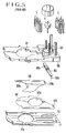
- Fig. 5 is an oblique view showing the conventional iris unit.
- Fig. 6 is a side view showing the lens of a video camera.
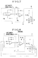
- Fig. 7 is a circuit diagram showing by way of example the circuit of the arrangement shown in Fig. 1.
- Fig. 8 is a circuit diagram showing by way of example the circuit of the conventional device shown in Fig. 4.
- Fig. 9 is a circuit diagram showing by way of example the circuit of a second embodiment of this invention.
- Fig. 10 is a circuit diagram showing by way of example the circuit of a third embodiment of the invention.
- Fig. 11 is a block diagram showing a video camera to which the
- Figs. 1 and 7 show the arrangement of a light quantity adjusting device which is arranged as a first embodiment of this invention.
- an output generating means that is a pulse generating circuit 8 consists of an operational amplifier, resistors and a capacitor.
- a light quantity control signal input terminal P is arranged to receive a light quantity control signal such as a luminance signal included in a video signal.
- An addition circuit means that is an addition circuit 9 which consists of an operational amplifier and resistors is arranged to superpose on each other the light quantity control signal and the output signal of the pulse generating circuit 8.
- a power amplifying circuit 10 which consists of a transistor and a resistor is arranged to make the control signal output from the addition circuit 9 into a signal for driving the magnetic rotor 13 of a motor part 11.
- the motor part 11 is provided with a driving coil 12 for causing the magnetic rotor 13 to rotate in accordance with the output signal of the power amplifying circuit 10.
- the magnetic rotor 13 is magnetized to have N and S poles for driving a control member.
- the light quantity control signal is, for example, a luminance signal included in the video signal as mentioned above.
- the output of the pulse generating circuit 8 is generated in a pulse wave form at a frequency higher than the time constant of the motor part 11 for moving the magnetic rotor 13 at a low speed by inchmeal.
- the light quantity control signal and the output of the pulse generating circuit 8 are superposed on each other by the addition circuit 9.
- the addition circuit 9 produces a control signal which is shown in Fig. 2.
- a reference symbol Va denotes a reference control degree
- a symbol Ve the light quantity control signal (one-dot chain line)
- a symbol Vp a driving control signal which is obtained by adding the pulse wave form to the light quantity control signal Ve.
- the output of the addition circuit 9 is amplified by the power amplifying circuit 10 and power is applied to the driving coil 12 accordingly.
- the driving control signal Vp causes the magnetic rotor 13 to rotate forward or backward.
- the magnetic rotor 13 remains stationary in actuality with a slight degree of vibration. A light quantity control member is thus accurately positioned. Further, the magnetic rotor 13 is urged by a spring to rotate in the direction of closing.
- the reference control degree Va is set at a value balanced with the force of the spring.
- Figs. 3 and 6 show a video camera arranged according to this invention to control a plurality of light quantity adjusting devices by using a timing sync signal thereof.
- the camera includes a timing sync signal generating circuit 14; a driver 15 which is arranged to drive a photo-electric converting means, that is a CCD 16 according to the timing of the timing sync signal generating circuit 14; the CCD 16 which is arranged to convert a light signal into an electrical signal; a video processing circuit 17 which is arranged to convert the output of the CCD 16 into a video signal in accordance with the output of the timing sync signal generating circuit 14; a detecting means, that is a light quantity detecting circuit 18 which is arranged to process the output of the CCD 16 into a light quantity control signal; a focus detecting circuit 19 which is arranged to process the output of the CCD 16 into a focus control signal; a manual switch 20 which is arranged to form a zoom control signal; an iris control circuit 21 which is arranged to form an
- a light flux from the object 30 (a reflected light having video information) is imaged on the CCD 16 through the focusing lens 29, the zoom lens 28, the light quantity control member 27, etc..
- the CCD 16 converts the image into an electrical signal.
- the driver 15 drives the CCD 16 to serially produce the electrical signal in accordance with the output of the timing sync signal generating circuit 14.
- This signal is supplied to the video processing circuit 17 to be converted into a video signal in accordance with the output of the timing sync signal generating circuit 14.
- the output signal of the CCD 16 is supplied also to the light quantity detecting circuit 18 and the focus detecting circuit 19 to be processed into a light quantity control signal and a focus control signal respectively.
- the manual switch 20 forms a zoom control signal.
- Each of the iris control circuit 21, the focus control circuit 23 and the zoom control circuit 22 forms the above-stated driving signal by adding the output of the timing sync signal generating circuit 14 to the applicable control signal.
- the driving signals thus formed cause the iris motor part 24, the focus motor 26 and the zoom motor 25 to move at a low speed by inchmeal respectively.
- the light quantity control member 27, the focus lens 29 and the zoom lens 28 are thus controlled with a high degree of accuracy.
- the arrangement of the embodiment permits circuit simplification. Further, the arrangement facilitates a countermeasure to noises by having the noises of the driving system such as a switching noise etc. at a single frequency.
- the light quantity is preferably controlled at a low speed.
- a low speed control is difficult with a DC motor.
- the invented arrangement to move the motor at a low speed by inchmeal makes such low speed control possible.
- Fig. 9 shows the control circuit of a second embodiment of the invention.
- the second embodiment differs from the circuit arrangement of Fig. 7 in respect of the power amplifying circuit.
- the power amplifying circuit 50 of the second embodiment is composed of two transistors and one resistor.
- the driving coil 12 is thus arranged to be excitable in different directions.
- the arrangement of the second embodiment is suited to a camera wherein the driving lever (see Fig. 5) is free and not urged by a spring in the direction of closing the aperture.
- the driving action on the magnetic rotor 13 by exciting the driving coil 12 is arranged to move the magnetic rotor 13 only in the direction of opening the aperture while the magnetic rotor 13 is arranged to be rotatable in both directions through the balance with the spring force urging it in the direction of closing the aperture.
- the second embodiment is arranged to rotate the magnetic rotor 13 in both directions by switching the direction in which a current is applied to the driving coil 12 from one direction over to the other.
- Fig. 10 shows the control circuit of a third embodiment of the invention.
- the arrangement of the third embodiment shown in Fig. 10 differs from Fig. 7 in that a detecting means, that is an F value detecting circuit 60 is added to the arrangement shown in Fig. 7.
- the term "F value" as used herein means the f-number of an optical system including the aperture of the light quantity control member (iris).
- the F value is changeable not only by a change in the aperture of the light quantity control member (iris) but also by the lens movement of the optical system. However, the F value is changeable to a greater degree by the change of the aperture of the light quantity control member than by the movement of the lens of the optical system.
- the F value detecting circuit 60 is arranged to detect the rotating position (rotation angle) of the magnetic rotor 13 by means of a Hall element as a change in voltage and thus virtually detects the aperture value obtained by the sliding movement of the diaphragm blades.
- the F value detecting circuit 60 consists of the Hall element, a differential amplifier and resistors.
- Fig. 11 shows a video camera which includes the control circuit shown in Fig. 10.
- the output of the F value detecting circuit 60 is supplied to a focus control circuit 23.
- the focus control circuit 23 is arranged to change its control over a focus motor 26 on the basis of F value information, because: The depth of field varies with the F value. If the F value is large, the object appears to be in focus to the eye of the camera operator even in the event of some deviation within the depth of field with a focusing lens 29 not in an in-focus position in actuality. In that case, it is not necessary to move the focusing lens 29.
- the embodiment is arranged to control the light quantity control member driving rotor to move it at a low speed by inchmeal by means of a driving control signal which is formed by adding to a light quantity control signal a continuous pulse wave form of a period which is shorter than the time constant of the motor.
- a driving control signal which is formed by adding to a light quantity control signal a continuous pulse wave form of a period which is shorter than the time constant of the motor.
- This arrangement dispenses with rotor rotation speed detecting means such as a damping coil. This permits reduction not only in size and weight of the apparatus but also in the cost of manufacture.
- the invented device employs an open-loop control system, the control operation is simple and, unlike closed-loop control, can be accomplished without any instability that results from oscillation or the like.
- the adoption of the method of driving by inchmeal in switching prevents any adverse effect of switching noise and ensures stable control. Therefore, the quantity of light can be accurately controlled.
Landscapes
- Engineering & Computer Science (AREA)
- Multimedia (AREA)
- Signal Processing (AREA)
- Diaphragms For Cameras (AREA)
- Automatic Focus Adjustment (AREA)
- Exposure Control For Cameras (AREA)
- Focusing (AREA)
Description
- This invention relates to a light quantity adjusting device to be used for a video camera or a still picture camera or more broadly to an optical apparatus such as a camera or the like.
- The video cameras and the still-picture film using cameras of these days are provided with automatic focusing devices and automatic light quantity adjusting devices such as automatic iris devices (hereinafter referred to as light quantity adjusting device). Generally, many of these light quantity adjusting devices are constructed on the basis of a closed-loop control system. The automatic iris device which is included in the video camera is also constructed on the basis of the closed-loop control system. Figs. 4, 5 and 8 of the accompanying drawings show the control system of the conventional automatic iris device.
- Referring to Figs. 4 and 8, the magnetic rotor 4 of a
motor part 1 is arranged to drive the diaphragm blades of the automatic iris device. Adriving coil 5 is provided for rotating the magnetic rotor 4. A power amplifyingcircuit 3 is provided for controlling the current applied to thedriving coil 5. Adamping coil 6 is provided for detecting the rotating speed of the magnetic rotor 4. A speed signal amplifyingcircuit 7 is arranged to amplify the speed detection output of thedamping coil 6. A light quantity control signal input terminal Q is arranged to receive a light quantity control signal which is, for example, a luminance signal included in a video signal. Acomparison computing circuit 2 generates an output which is in proportion to a difference between a speed control signal output from the speed signal amplifyingcircuit 7 and the light quantity control signal. Thedriving coil 5, the magnetic rotor 4 and thedamping coil 6 are included in themotor part 1. - The conventional automatic iris device is arranged to have the output of the
damping coil 6 amplified by the speed signal amplifyingcircuit 7 and to have the amplified signal negatively fed back to thecomparison computing circuit 2 as a speed control signal. - Referring to Fig. 5, a
base plate 100 has anaperture 101 which allows a light flux to pass therethrough and asupport part 102 on which the magnetic rotor 4 and thecoils driving lever 105 is secured to the rotating shaft of the magnetic rotor 4 and is arranged to swing accordingly as the magnetic rotor 4 rotates. A spring is arranged to constantly urge thedriving lever 105 to move in the direction of closing the aperture.Diaphragm blades apertures retaining plate 110 has anaperture 110a formed therein in such a way as to allow the light flux to pass therethrough. - The
diaphragm blades base plate 100 and theretaining plate 110. Thepins driving lever 105 are inserted intoslots driving lever 105 to cause thediaphragm blades apertures - The conventional automatic iris device which is arranged in the above-stated manner, however, has presented the following problems which must be solved:
- (i) The device necessitates the provision of the speed detecting
damping coil 6, which occupies a relatively large space. This not only increases the size of the device but also prevents reduction in cost. - (ii) The
damping coil 6 and thedriving coil 5 are disposed close to each other. Therefore, a change in a current applied to thedriving coil 5 brings about a current at thedamping coil 6 due to mutual induction. This current lowers the accuracy of the rotor speed detection signal produced by using thedamping coil 6. Since the detection signal is negatively fed back to thedriving coil 5, the control over the speed and the position of the magnetic rotor 4 tends to become unstable. - It is an aspect of this invention to provide a light quantity adjusting device or an optical apparatus having the light quantity adjusting device which is arranged to obviate the necessity of the speed detecting damping coil by energizing the above-stated driving coil with a rectangular pulse output of a period shorter than the time constant of electromagnetic driving means.
- According to the invention this object is accomplished by a light quantity adjusting device comprising: a) a light quantity adjusting member arranged to adjust a quantity of light; b) electromagnetic driving means for moving said light quantity adjusting member to adjust the quantity of light; c) output generating means being arranged to generate a pulse output for a period shorter than a time constant of said electromagnetic driving means; and d) addition circuit means for adding a target signal indicative of a desired quantity of light to said pulse output generated by said output generating means and supplying a driving output to said electromagnetic driving means.
- Furthermore, this object is accomplished by an optical apparatus having a light quantity adjusting device, comprising: a) an optical lens arranged to guide an object light to photo-electric converting means; b) a light quantity adjusting member disposed in the vicinity of said optical lens and arranged to adjust a quantity of light; c) electromagnetic driving means for moving said light quantity adjusting member to adjust the quantity of light; and d) light quantity detecting means for detecting the quantity of light incident on said photo-electric converting means; e) output generating means being arranged to generate a pulse output for a period shorter than a time constant of said electromagnetic driving means; and f) addition circuit means for adding a target signal indicative of a desired quantity of light to said pulse output generated by said output generating means and supplying a driving output to said electromagnetic driving means.
- The above object and features of the invention will become apparent from the following detailed description of embodiments thereof taken in connection with the accompanying drawings.
- Fig. 1 is a block diagram showing the arrangement of a light quantity adjusting device embodying this invention. Fig. 2 is a graph showing the wave form of a driving control signal. Fig. 3 is a block diagram showing the arrangement of a video camera to which this invention is applied. Fig. 4 shows the arrangement of the conventional device. Fig. 5 is an oblique view showing the conventional iris unit. Fig. 6 is a side view showing the lens of a video camera. Fig. 7 is a circuit diagram showing by way of example the circuit of the arrangement shown in Fig. 1. Fig. 8 is a circuit diagram showing by way of example the circuit of the conventional device shown in Fig. 4. Fig. 9 is a circuit diagram showing by way of example the circuit of a second embodiment of this invention. Fig. 10 is a circuit diagram showing by way of example the circuit of a third embodiment of the invention. Fig. 11 is a block diagram showing a video camera to which the circuit of Fig. 10 is applied.
- Figs. 1 and 7 show the arrangement of a light quantity adjusting device which is arranged as a first embodiment of this invention. Referring to these drawings, an output generating means, that is a pulse generating
circuit 8 consists of an operational amplifier, resistors and a capacitor. A light quantity control signal input terminal P is arranged to receive a light quantity control signal such as a luminance signal included in a video signal. An addition circuit means, that is anaddition circuit 9 which consists of an operational amplifier and resistors is arranged to superpose on each other the light quantity control signal and the output signal of thepulse generating circuit 8. A power amplifyingcircuit 10 which consists of a transistor and a resistor is arranged to make the control signal output from theaddition circuit 9 into a signal for driving themagnetic rotor 13 of amotor part 11. Themotor part 11 is provided with adriving coil 12 for causing themagnetic rotor 13 to rotate in accordance with the output signal of the power amplifyingcircuit 10. Themagnetic rotor 13 is magnetized to have N and S poles for driving a control member. - With the first embodiment of the invention arranged in the above-stated manner, it operates as follows: The light quantity control signal is, for example, a luminance signal included in the video signal as mentioned above. The output of the
pulse generating circuit 8 is generated in a pulse wave form at a frequency higher than the time constant of themotor part 11 for moving themagnetic rotor 13 at a low speed by inchmeal. The light quantity control signal and the output of thepulse generating circuit 8 are superposed on each other by theaddition circuit 9. As a result, theaddition circuit 9 produces a control signal which is shown in Fig. 2. Referring to Fig. 2, a reference symbol Va denotes a reference control degree; a symbol Ve the light quantity control signal (one-dot chain line); and a symbol Vp a driving control signal which is obtained by adding the pulse wave form to the light quantity control signal Ve. - The output of the
addition circuit 9 is amplified by the power amplifyingcircuit 10 and power is applied to thedriving coil 12 accordingly. When the light quantity control signal Ve is equal to the reference control degree Va, the driving control signal Vp causes themagnetic rotor 13 to rotate forward or backward. However, since the period of the pulse wave form is much shorter than the time constant of themotor part 11, themagnetic rotor 13 remains stationary in actuality with a slight degree of vibration. A light quantity control member is thus accurately positioned. Further, themagnetic rotor 13 is urged by a spring to rotate in the direction of closing. The reference control degree Va is set at a value balanced with the force of the spring. - In a case where the light quantity control signal Ve is deviating from the reference control degree Va, the balance between the forward rotation and reverse rotation of the
magnetic rotor 13 is lost and themagnetic rotor 13 is driven to rotate at a low speed in the forward or reverse direction. Then, the position of the light quantity control member is controlled at a low speed accordingly. - Figs. 3 and 6 show a video camera arranged according to this invention to control a plurality of light quantity adjusting devices by using a timing sync signal thereof. Referring to these drawings, the camera includes a timing sync signal generating circuit 14; a driver 15 which is arranged to drive a photo-electric converting means, that is a CCD 16 according to the timing of the timing sync signal generating circuit 14; the CCD 16 which is arranged to convert a light signal into an electrical signal; a video processing circuit 17 which is arranged to convert the output of the CCD 16 into a video signal in accordance with the output of the timing sync signal generating circuit 14; a detecting means, that is a light quantity detecting circuit 18 which is arranged to process the output of the CCD 16 into a light quantity control signal; a focus detecting circuit 19 which is arranged to process the output of the CCD 16 into a focus control signal; a manual switch 20 which is arranged to form a zoom control signal; an iris control circuit 21 which is arranged to form an iris driving signal by adding together the output of the timing sync signal generating circuit 14 and that of the light quantity detecting circuit 18; a zoom control circuit 22 which is arranged to form a zoom motor driving signal by adding together the output of the timing sync signal generating circuit 14 and that of the manual switch 20; a focus control circuit 23 which is arranged to form a focus motor driving signal by adding together the output of the timing sync signal generating circuit 14 and that of the focus detecting circuit 19; an iris motor part 24 which is arranged to drive and control a light quantity adjusting member, that is a light quantity control member 27 by receiving the output of the iris control circuit 21; a zoom motor 25 which is arranged to drive and control a zoom lens 28 by receiving the output of the zoom control circuit 22; a focus motor 26 which is arranged to drive and control a focusing lens 29 by receiving the output of the focus control circuit 23; the light quantity control member 27 which is arranged to control the quantity of light incident on the CCD 16; the zoom lens 28 which is used for controlling the magnification of an image incident on the CCD 16; and the focusing lens 29 which is used for controlling the focus state of the image formed on the CCD 16. A
reference numeral 30 denotes a picture-taking object. - In the embodiment described above, a light flux from the object 30 (a reflected light having video information) is imaged on the
CCD 16 through the focusinglens 29, thezoom lens 28, the lightquantity control member 27, etc.. TheCCD 16 converts the image into an electrical signal. Thedriver 15 drives theCCD 16 to serially produce the electrical signal in accordance with the output of the timing syncsignal generating circuit 14. This signal is supplied to thevideo processing circuit 17 to be converted into a video signal in accordance with the output of the timing syncsignal generating circuit 14. The output signal of theCCD 16 is supplied also to the lightquantity detecting circuit 18 and thefocus detecting circuit 19 to be processed into a light quantity control signal and a focus control signal respectively. Meanwhile, themanual switch 20 forms a zoom control signal. Each of theiris control circuit 21, thefocus control circuit 23 and thezoom control circuit 22 forms the above-stated driving signal by adding the output of the timing syncsignal generating circuit 14 to the applicable control signal. The driving signals thus formed cause theiris motor part 24, thefocus motor 26 and thezoom motor 25 to move at a low speed by inchmeal respectively. The lightquantity control member 27, thefocus lens 29 and thezoom lens 28 are thus controlled with a high degree of accuracy. - Since a plurality of driving devices can be controlled by one and the same pulse signal, the arrangement of the embodiment permits circuit simplification. Further, the arrangement facilitates a countermeasure to noises by having the noises of the driving system such as a switching noise etc. at a single frequency.
- In cases where the vertical sync signal of the video signal is used, a disorder in the image of one picture due to driving control over the quantity of light becomes unvarying for consecutive pictures. Therefore, the use of the vertical sync signal effectively prevents consecutive pictures from fluctuating and flickering.
- Further, it is undesirable to have any sudden change in the image light quantity of such consecutive pictures that are obtained by the video camera. The light quantity is preferably controlled at a low speed. However, such a low speed control is difficult with a DC motor. Whereas, the invented arrangement to move the motor at a low speed by inchmeal makes such low speed control possible.
- Fig. 9 shows the control circuit of a second embodiment of the invention. The second embodiment differs from the circuit arrangement of Fig. 7 in respect of the power amplifying circuit. Referring to Fig. 9, the power amplifying circuit 50 of the second embodiment is composed of two transistors and one resistor. The driving
coil 12 is thus arranged to be excitable in different directions. The arrangement of the second embodiment is suited to a camera wherein the driving lever (see Fig. 5) is free and not urged by a spring in the direction of closing the aperture. In the case of the first embodiment, the driving action on themagnetic rotor 13 by exciting the drivingcoil 12 is arranged to move themagnetic rotor 13 only in the direction of opening the aperture while themagnetic rotor 13 is arranged to be rotatable in both directions through the balance with the spring force urging it in the direction of closing the aperture. Whereas, the second embodiment is arranged to rotate themagnetic rotor 13 in both directions by switching the direction in which a current is applied to the drivingcoil 12 from one direction over to the other. - Fig. 10 shows the control circuit of a third embodiment of the invention. The arrangement of the third embodiment shown in Fig. 10 differs from Fig. 7 in that a detecting means, that is an F
value detecting circuit 60 is added to the arrangement shown in Fig. 7. The term "F value" as used herein means the f-number of an optical system including the aperture of the light quantity control member (iris). The F value is changeable not only by a change in the aperture of the light quantity control member (iris) but also by the lens movement of the optical system. However, the F value is changeable to a greater degree by the change of the aperture of the light quantity control member than by the movement of the lens of the optical system. - The F
value detecting circuit 60 is arranged to detect the rotating position (rotation angle) of themagnetic rotor 13 by means of a Hall element as a change in voltage and thus virtually detects the aperture value obtained by the sliding movement of the diaphragm blades. The Fvalue detecting circuit 60 consists of the Hall element, a differential amplifier and resistors. - Fig. 11 shows a video camera which includes the control circuit shown in Fig. 10. The output of the F
value detecting circuit 60 is supplied to afocus control circuit 23. Thefocus control circuit 23 is arranged to change its control over afocus motor 26 on the basis of F value information, because: The depth of field varies with the F value. If the F value is large, the object appears to be in focus to the eye of the camera operator even in the event of some deviation within the depth of field with a focusinglens 29 not in an in-focus position in actuality. In that case, it is not necessary to move the focusinglens 29. - As described in the foregoing, the embodiment is arranged to control the light quantity control member driving rotor to move it at a low speed by inchmeal by means of a driving control signal which is formed by adding to a light quantity control signal a continuous pulse wave form of a period which is shorter than the time constant of the motor. This arrangement dispenses with rotor rotation speed detecting means such as a damping coil. This permits reduction not only in size and weight of the apparatus but also in the cost of manufacture.
- Since the invented device employs an open-loop control system, the control operation is simple and, unlike closed-loop control, can be accomplished without any instability that results from oscillation or the like. The adoption of the method of driving by inchmeal in switching prevents any adverse effect of switching noise and ensures stable control. Therefore, the quantity of light can be accurately controlled.
Claims (24)
- A light quantity adjusting device comprising:a) a light quantity adjusting member (27) arranged to adjust a quantity of light;b) electromagnetic driving means (11, 12, 13; 24) for moving said light quantity adjusting member (27) to adjust the quantity of light;c) output generating means (8) being arranged to generate a pulse output for a period shorter than a time constant of said electromagnetic driving means (11, 12, 13; 24); andd) addition circuit means (9; 21) for adding a target signal (P) indicative of a desired quantity of light to said pulse output generated by said output generating means (8) and supplying a driving output to said electromagnetic driving means (11, 12, 13; 24).
- A device according to claim 1, wherein said electromagnetic driving means (11, 12, 13; 24) is composed of a driving coil (12) and a magnetic rotor (13).
- A device according to claim 1, wherein said light quantity adjusting member (27) is composed of diaphragm blades.
- A device according to claim 1, wherein said target signal (P) is represented by a voltage value.
- A device according to claim 2, wherein said driving output is arranged to drive said driving coil (12) only in one direction.
- A device according to claim 2, wherein said driving output is arranged to drive said driving coil (12) both in opposite directions.
- A device according to claim 1, further comprising detecting means (18) for detecting a state of said light quantity adjusting member (27), said detecting means (18) being arranged to detect a light quantity value which is obtained on the basis of a moving position of said light quantity adjusting member (27).
- A device according to claim 2, further comprising detecting means (60) for detecting a rotating position of said magnetic rotor (13), said detecting means (60) being arranged to detect a light quantity value which is based on a moving position of said light quantity adjusting member (27) by detecting the rotating position of said magnetic rotor (13).
- A device according to claim 7 or 8, wherein said detecting means (60) includes a Hall element and is arranged to produce detected information as a voltage value.
- A device according to claim 3, wherein said light quantity adjusting member (27) is arranged to adjust said quantity of light by moving a plurality of diaphragm blades to vary an aperture defined thereby.
- An optical apparatus having a light quantity adjusting device, comprising:a) an optical lens (28, 29) arranged to guide an object light to photo-electric converting means (16);b) a light quantity adjusting member (27) disposed in the vicinity of said optical lens (28, 29) and arranged to adjust a quantity of said object light;c) electromagnetic driving means (11, 12, 13; 24) for moving said light quantity adjusting member (27) to adjust the quantity of light; andd) light quantity detecting means (18) for detecting the quantity of light incident on said photo-electric converting means (16);e) output generating means (8) being arranged to generate a pulse output for a period shorter than a time constant of said electromagnetic driving means (11, 12, 13; 24); andf) addition circuit means (9; 21) for adding a target signal (P) indicative of a desired quantity of light to said pulse output generated by said output generating means (8) and supplying a driving output to said electromagnetic driving means (11, 12, 13; 24).
- An optical apparatus according to claim 11, wherein said electromagnetic driving means (11, 12, 13; 24) is composed of a driving coil (12) and a magnetic rotor (13).
- An apparatus according to claim 11, further comprising a video processing circuit (17) arranged to convert an output of said photo-electric converting means (16) into a video signal in accordance with a timing signal.
- An apparatus according to claim 13, wherein said pulse output generated by said output generating means (8, 9, 10; 21) is of a period which is determined by using a period of said timing signal used by said video processing circuit (17).
- An apparatus according to claim 14, wherein said timing signal is arranged to coincide with a vertical synchronizing signal.
- An apparatus according to claim 11, wherein said light quantity adjusting member (27) is composed of diaphragm blades.
- An apparatus according to claim 11, wherein said target signal (P) is represented by a voltage value.
- An apparatus according to claim 12, wherein said driving output is arranged to drive said driving coil (12) only in one direction.
- An apparatus according to claim 12, wherein said driving output is arranged to drive said driving coil (12) both in opposite directions.
- An apparatus according to claim 11, further comprising detecting means (18) for detecting a state of said light quantity adjusting member (27), said detecting means being arranged to detect a light quantity value which is obtained on the basis of a moving position of said light quantity adjusting member (27).
- An apparatus according to claim 12, further comprising detecting means (60) for detecting a rotating position of said magnetic rotor (13), said detecting means (60) being arranged to detect a light quantity value which is based on a moving position of said light quantity adjusting member (27) by detecting the rotating position of said magnetic rotor (13).
- An apparatus according to claim 20 or 21, wherein said detecting means (60) includes a Hall element and is arranged to produce detected information as a voltage value.
- An apparatus according to claim 16, wherein said light quantity adjusting member (27) is arranged to adjust said quantity of light by moving a plurality of diaphragm blades to vary an aperture defined thereby.
- An apparatus according to claim 20 or 21, further comprising focus control means (23) arranged to perform focus control on the basis of the information detected by said detecting means (60).
Applications Claiming Priority (2)
| Application Number | Priority Date | Filing Date | Title |
|---|---|---|---|
| JP1322024A JP2520491B2 (en) | 1989-12-12 | 1989-12-12 | Optical equipment |
| JP322024/89 | 1989-12-12 |
Publications (3)
| Publication Number | Publication Date |
|---|---|
| EP0440927A2 EP0440927A2 (en) | 1991-08-14 |
| EP0440927A3 EP0440927A3 (en) | 1991-12-27 |
| EP0440927B1 true EP0440927B1 (en) | 1995-09-27 |
Family
ID=18139070
Family Applications (1)
| Application Number | Title | Priority Date | Filing Date |
|---|---|---|---|
| EP90123859A Expired - Lifetime EP0440927B1 (en) | 1989-12-12 | 1990-12-11 | Light quantity adjusting device |
Country Status (5)
| Country | Link |
|---|---|
| US (1) | US5196940A (en) |
| EP (1) | EP0440927B1 (en) |
| JP (1) | JP2520491B2 (en) |
| CA (1) | CA2031905C (en) |
| DE (1) | DE69022711T2 (en) |
Families Citing this family (7)
| Publication number | Priority date | Publication date | Assignee | Title |
|---|---|---|---|---|
| JP3364945B2 (en) * | 1992-01-31 | 2003-01-08 | ソニー株式会社 | Camera shake correction device and camera shake correction method |
| DE4243279A1 (en) * | 1992-12-21 | 1994-06-23 | Bayer Ag | Substituted triplets |
| US5705873A (en) * | 1993-12-22 | 1998-01-06 | Canon Denshi Kabushiki Kaisha | Light-quantity control device |
| JPH07295023A (en) * | 1994-04-22 | 1995-11-10 | Nikon Corp | Camera aperture control device |
| US20050226612A1 (en) * | 2004-04-08 | 2005-10-13 | Asia Optical Co., Inc. | Automatic diaphragm assembly with a variable aperture for a lens |
| CN112859280B (en) * | 2015-09-08 | 2023-07-14 | Lg伊诺特有限公司 | Lens driving device, camera module and optical device including the device |
| CN118413730B (en) * | 2024-07-01 | 2024-10-01 | 杭州海康威视数字技术股份有限公司 | Aperture driving circuit and camera |
Family Cites Families (14)
| Publication number | Priority date | Publication date | Assignee | Title |
|---|---|---|---|---|
| JPS4859318A (en) * | 1971-11-29 | 1973-08-20 | ||
| US3995208A (en) * | 1975-04-25 | 1976-11-30 | Parr Robert L | Control circuit |
| DE2518675B2 (en) * | 1975-04-26 | 1977-07-28 | Braun Ag, 6000 Frankfurt | EXPOSURE CONTROLLER FOR FILM CAMERAS |
| JPS545298A (en) * | 1977-06-13 | 1979-01-16 | Ikeda Matsuhisa | Device for cutting log |
| JPS55105479A (en) * | 1979-02-06 | 1980-08-13 | Sony Corp | Automatic diaphragm device |
| JPS5643629A (en) * | 1979-09-18 | 1981-04-22 | Olympus Optical Co Ltd | Diaphragm control unit |
| US4325614A (en) * | 1980-12-16 | 1982-04-20 | Polaroid Corporation | Exposure control system with shutter operation controlled by a microcomputer |
| JPS6051374A (en) * | 1983-08-30 | 1985-03-22 | Sharp Corp | Solid-state image pickup device |
| US4651068A (en) * | 1984-10-01 | 1987-03-17 | Electro-Craft Corporation | Brushless motor control circuitry with optimum current vector control |
| JPS6238084A (en) * | 1985-08-12 | 1987-02-19 | Matsushita Electric Ind Co Ltd | Automatic light quantity adjusting device |
| JPH01123236A (en) * | 1987-11-09 | 1989-05-16 | Konica Corp | Automatic developing machine |
| JPH0215248A (en) * | 1988-07-04 | 1990-01-18 | Seikosha Co Ltd | Automatic focusing device for camera |
| JPH02105121A (en) * | 1988-10-14 | 1990-04-17 | Olympus Optical Co Ltd | Diaphragm control device |
| US5049997A (en) * | 1989-04-10 | 1991-09-17 | Fuji Photo Film Co., Ltd. | Video camera exposure control method and apparatus for preventing improper exposure due to changing object size or displacement and luminance difference between the object and background |
-
1989
- 1989-12-12 JP JP1322024A patent/JP2520491B2/en not_active Expired - Lifetime
-
1990
- 1990-12-10 CA CA002031905A patent/CA2031905C/en not_active Expired - Fee Related
- 1990-12-11 EP EP90123859A patent/EP0440927B1/en not_active Expired - Lifetime
- 1990-12-11 US US07/625,461 patent/US5196940A/en not_active Expired - Lifetime
- 1990-12-11 DE DE69022711T patent/DE69022711T2/en not_active Expired - Lifetime
Also Published As
| Publication number | Publication date |
|---|---|
| EP0440927A3 (en) | 1991-12-27 |
| US5196940A (en) | 1993-03-23 |
| JPH03181921A (en) | 1991-08-07 |
| EP0440927A2 (en) | 1991-08-14 |
| CA2031905C (en) | 1996-04-30 |
| DE69022711T2 (en) | 1996-04-11 |
| CA2031905A1 (en) | 1991-06-13 |
| DE69022711D1 (en) | 1995-11-02 |
| JP2520491B2 (en) | 1996-07-31 |
Similar Documents
| Publication | Publication Date | Title |
|---|---|---|
| US6408135B1 (en) | Control device for image blur correction | |
| CN101183204B (en) | Electromagnetic driving apparatus and optical apparatus | |
| EP0485163A2 (en) | A zoom tracking apparatus | |
| US5705873A (en) | Light-quantity control device | |
| US5140357A (en) | Automatic focusing device wherein loop gain is set responsively to variation of magnification | |
| US5196940A (en) | Electromagnetically-driven automatic iris device not requiring speed detecting damping coil | |
| JP3925751B2 (en) | Angle correction device for taking lens | |
| US5590236A (en) | Speed controller or an instrument having a speed controller including detection means for linearly detecting the amount of rotation less than one full rotation of a rotating member | |
| JPH11190864A (en) | Imaging device with tilt mechanism, method, and storage medium | |
| JP2001004914A (en) | Focus control device | |
| JPS5926708A (en) | How to focus a zoom lens | |
| JP2614351B2 (en) | Light amount control device having position detecting device | |
| JPS6387871A (en) | automatic focus device | |
| JP7516096B2 (en) | Imaging device, lens device, camera system, and program | |
| JPS63163312A (en) | Automatic focusing device and its lens driving mechanism | |
| JP3521932B2 (en) | Camera system | |
| JPH03137608A (en) | Video camera | |
| JPH0466921A (en) | Video camera | |
| US6064432A (en) | Light quantity control device | |
| JPS62272218A (en) | Autofocusing device | |
| JPS63163310A (en) | Automatic focusing device and its lens driving device | |
| JP5072303B2 (en) | Light control system and optical device | |
| JPS58159510A (en) | Focus adjusting device of optical equipment | |
| JP2001083394A (en) | Imaging device | |
| JPH03185411A (en) | Photography equipment |
Legal Events
| Date | Code | Title | Description |
|---|---|---|---|
| PUAI | Public reference made under article 153(3) epc to a published international application that has entered the european phase |
Free format text: ORIGINAL CODE: 0009012 |
|
| AK | Designated contracting states |
Kind code of ref document: A2 Designated state(s): DE FR GB NL |
|
| PUAL | Search report despatched |
Free format text: ORIGINAL CODE: 0009013 |
|
| AK | Designated contracting states |
Kind code of ref document: A3 Designated state(s): DE FR GB NL |
|
| 17P | Request for examination filed |
Effective date: 19920602 |
|
| 17Q | First examination report despatched |
Effective date: 19940406 |
|
| GRAA | (expected) grant |
Free format text: ORIGINAL CODE: 0009210 |
|
| AK | Designated contracting states |
Kind code of ref document: B1 Designated state(s): DE FR GB NL |
|
| PG25 | Lapsed in a contracting state [announced via postgrant information from national office to epo] |
Ref country code: FR Effective date: 19950927 |
|
| REF | Corresponds to: |
Ref document number: 69022711 Country of ref document: DE Date of ref document: 19951102 |
|
| PG25 | Lapsed in a contracting state [announced via postgrant information from national office to epo] |
Ref country code: GB Effective date: 19951227 |
|
| EN | Fr: translation not filed | ||
| PLBE | No opposition filed within time limit |
Free format text: ORIGINAL CODE: 0009261 |
|
| STAA | Information on the status of an ep patent application or granted ep patent |
Free format text: STATUS: NO OPPOSITION FILED WITHIN TIME LIMIT |
|
| GBPC | Gb: european patent ceased through non-payment of renewal fee |
Effective date: 19951227 |
|
| 26N | No opposition filed | ||
| PGFP | Annual fee paid to national office [announced via postgrant information from national office to epo] |
Ref country code: NL Payment date: 20021227 Year of fee payment: 13 |
|
| PG25 | Lapsed in a contracting state [announced via postgrant information from national office to epo] |
Ref country code: NL Free format text: LAPSE BECAUSE OF NON-PAYMENT OF DUE FEES Effective date: 20040701 |
|
| NLV4 | Nl: lapsed or anulled due to non-payment of the annual fee |
Effective date: 20040701 |
|
| PGFP | Annual fee paid to national office [announced via postgrant information from national office to epo] |
Ref country code: DE Payment date: 20091203 Year of fee payment: 20 |
|
| PG25 | Lapsed in a contracting state [announced via postgrant information from national office to epo] |
Ref country code: DE Free format text: LAPSE BECAUSE OF EXPIRATION OF PROTECTION Effective date: 20101211 |