EP0440216B1 - White balance control system - Google Patents
White balance control system Download PDFInfo
- Publication number
- EP0440216B1 EP0440216B1 EP91101238A EP91101238A EP0440216B1 EP 0440216 B1 EP0440216 B1 EP 0440216B1 EP 91101238 A EP91101238 A EP 91101238A EP 91101238 A EP91101238 A EP 91101238A EP 0440216 B1 EP0440216 B1 EP 0440216B1
- Authority
- EP
- European Patent Office
- Prior art keywords
- light
- control circuit
- white balance
- circuit
- colours
- Prior art date
- Legal status (The legal status is an assumption and is not a legal conclusion. Google has not performed a legal analysis and makes no representation as to the accuracy of the status listed.)
- Expired - Lifetime
Links
Images




Classifications
-
- H—ELECTRICITY
- H04—ELECTRIC COMMUNICATION TECHNIQUE
- H04N—PICTORIAL COMMUNICATION, e.g. TELEVISION
- H04N9/00—Details of colour television systems
- H04N9/64—Circuits for processing colour signals
- H04N9/73—Colour balance circuits, e.g. white balance circuits or colour temperature control
Definitions
- the present invention relates to a white balance control system for a projection television receiver, and more particularly to a white balance control system for automatically controlling balance of color when quantities of light of the three primary colors decrease with time.
- a rear projection system as one of the systems of the projection television is shown in Fig. 5.
- a picture tube 1 produces a pictorial image which is expanded by a lens 2. The image is reflected on opposing reflecting mirrors 3 and 4 and reproduced on a light-transmissible screen 5.
- Fig. 6 shows another projection television receiver where the image is reproduced on a reflecting screen 6 from the front thereof.
- a refraction system shown in Fig. 7 and a reflection system shown in Fig. 8 dependent on the type of picture tubes 1.
- the lens 2 is provided in front of a fluorescent screen of the picture tube 1. The lens 2 expands and reproduces the image on the reflecting screen 6.
- a picture tube 8 has a fluorescent screen 9 and a reflecting mirror 10 provided in the tube 8.
- the image reflected on the reflecting mirror 10 is expanded through a Schmidt lens 11 and reproduced on the reflecting screen 6.
- the light-transmissible screen 5 is made of a material having a high light transmittance, such as a Fresnel lens and a lenticular sheet.
- the fluorescent screen 7 (9) of the picture tube has a low luminous efficacy particularly for blue. Accordingly, in order to maintain the balance with the other colors, the current i supplied to the blue picture tube is increased. Thus the joule heat caused by the current i heats the screen of the blue picture tube, thereby quickly deteriorating it.
- the luminous efficacy of the blue light is further decreased.
- the quantities of red and green light relatively increase.
- the picture on the screen 6 will thus gradually assume a yellowish color.
- the color can be corrected by manipulating a dial for controlling the color balance.
- the adjusting operation is complicated.
- the United States Patent US-A-3 877 068 discloses a color balance apparatus for a color television comprising a computing circuit which calculates mean quantities of the outputs of photoelectric sensor elements for the three primary colors.
- a reference circuit is provided which generates color balance controlling signals by comparing each mean value of primary color light to each of a set of theoretically predetermined standard values.
- the United States Patent US-A-4 485 394 discloses a system for automatic correction of convergence and grey scale in color television.
- At least one light sensor is permanently positioned on the screen of a projection receiver.
- Means are provided for blanking two of the three cathode ray tubes, such that the sensor successively receives light of each of three primary colors.
- the output of the sensor is amplified for each of the cathode ray tubes in sequential order and the outputs are compared to preset values to develop error signals according to which the grey scale is corrected.
- the object of the present invention is to provide a white balance control system in which the above-described problem of yellowing is overcome so as to constantly provide a pictorial image in appropriate color.
- Fig. 1 shows a projection television receiver to which a white balance control system of the first embodiment is applied.
- the receiver has CRT (cathode-ray tube) displays which project pictorial images from the front thereof.
- the control system of the television receiver comprises a video signal output circuit 12, a signal processing circuit 13, a synchronizing circuit 14, color output control circuits 15, 16 and 17.
- the video signal output circuit 12 is connected to a video signal source such as a television tuner, CATV tuner, video tape recorder and video disk player, so as to be fed with video signals.
- the signal processing circuit 13 produces red, green and blue video signals in accordance with the output signal of the output circuit 12.
- the synchronizing circuit 14 controls the projection timing of the video signals applied to the control circuits 15 to 17 to prevent deflection of color and decrease of resolution.
- the video signals are applied to the R-output control circuit 15, G-output control circuit 16 and a B-output control circuit 17, the output signals of which are fed to respective picture tubes 18, 19 and 20 so as to control the light emitting operation thereof.
- each of the picture tubes 18, 19 and 20 produces an image and which is projected on to a light-transmissible screen 24 through a corresponding one of the projection lenses 21, 22 and 23.
- Light quantity sensors 25 are provided on the screen 24, for example at the four corners of the screen where the pictorial image is not affected, to detect the quantity of light projected onto the light transmissible screen 24.
- the sensor 25 may be embedded in a black striped portion of a lenticular sheet if the sensor is small enough.
- a pickup unit (camera), photodiode, phototransistor, photoelectric converter elements each having different spectral sensitivity characteristics, or further, a packaged color sensor may be used as the light quantity sensor 25.
- a color sensor PD170V1 manufactured by Sharp Co. Ltd may also be used.
- the output signals of the light quantity sensors 25 are fed to a white balance control circuit 26 to adjust the intensity of beam of each primary color so as to reproduce appropriate white on the screen in a wide range from high luminance to low luminance.
- the white balance control circuit 26 has a color separation circuit 26a for splitting the signal detected by the light quantity sensor 25 into red, green and blue components. The ratio of quantities of light corresponding to each component is calculated by a light quantity calculator 26b.
- the white balance control circuit further has a memory 26c such as an EEPROM wherein a reference light quantity ratio of the red, green and blue components is stored. The light quantity ratio calculated in the light quantity calculator 25b is compared with the reference light quantity ratio by a comparator 26d.
- the reference ratio stored in the memory 26c during the production of the receiver is obtained as follows. After adjustments such as conversence are completed, a standard signal is projected on the screen 24 and the light quantity is detected by the sensors 25. A standard ratio is calculated in dependency on the detected light quantity of the standard signal and converted into data corresponding to each quantity of light.
- the white balance controlling circuit 26 is further provided with a correction circuit 26e for correcting the actual ratio when the ratio calculated by the calculator 26b does not coincide with the reference ratio stored in the memory 26c.
- the correction circuit 26e corrects the actual ratio based on the smallest light quantity of the three colors which decreases the most.
- a step 301 it is determined whether the signal is fed from the light quantity sensor 25.
- the signal is separated into red, green and blue components in the separation circuit 26a (step 302).
- the light quantity calculator 26b calculates the ratio of the quantities of light corresponding to red, green and blue.
- the reference light quantity ratio in the memory 26c is read (step 304) and compared with the calculated ratio (step 305). If the ratios match, the program returns to the step 301 to repeat the program.
- the correction section 26e is operated to correct the actual ratio. More particularly, an appropriate white balance is obtained when the percentages of red, green and blue lights are 30%, 59% and 11%, respectively.
- the quantities of light of one of the color components for example the blue
- the quantities of light of other components red and green
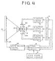
- Fig. 4 shows the second embodiment of the present invention where a liquid crystal display is provided instead of the CRT display.
- the same numerals as those in Fig. 1 designate the same parts in Fig. 4 as Fig. 1, and therefore, the description thereof is omitted.
- the video signals controlled by the R-output control circuit 15, G-output control circuit 16 and B-output control circuit 17 are applied to liquid crystal display panels 18a, 19a and 20a, respectively, thereby reproducing images on each panel.
- Dichroic mirrors M serve as prisms which transmit the image on each display panel 18a, 19a and 20a to the lens 22.
- the ratio between the quantities of light corresponding to the primary color components are corrected based on the quantity of light of the most deteriorated color component.
- the present embodiment is more effective in controlling the color of the image reproduced on the screen than in the television receiver provided with CRT displays. If the liquid crystal itself deteriorates, the contrast of the images weakens. However, an appropriate balance of color can be obtained by darkening the entire image.
- the light quantity sensor is provided for detecting quantity of light of all of the color components, red, green and blue
- the embodiments may be modified to detect only the quantity of light of the color which most easily deteriorates, namely blue, thus enabling to reduce the cost.
- the present invention may be applied to rear projection television receivers and to ordinary television receivers.
- the present invention provides a white balance control system wherein a ratio between the quantities of lights of the primary color components is automatically corrected in accordance with the decrease of the quantity of light projected on the screen, so that a desirable color of the images is always obtained.
Landscapes
- Engineering & Computer Science (AREA)
- Multimedia (AREA)
- Signal Processing (AREA)
- Video Image Reproduction Devices For Color Tv Systems (AREA)
- Processing Of Color Television Signals (AREA)
Description
- The present invention relates to a white balance control system for a projection television receiver, and more particularly to a white balance control system for automatically controlling balance of color when quantities of light of the three primary colors decrease with time.
- In recent years, in order to provide a wider screen for a television receiver, it has become common to employ a projection television system.
- A rear projection system as one of the systems of the projection television is shown in Fig. 5. A picture tube 1 produces a pictorial image which is expanded by a
lens 2. The image is reflected on opposing reflectingmirrors 3 and 4 and reproduced on a light-transmissible screen 5. - Fig. 6 shows another projection television receiver where the image is reproduced on a reflecting screen 6 from the front thereof.
- There are other types of projection systems such as a refraction system shown in Fig. 7 and a reflection system shown in Fig. 8 dependent on the type of picture tubes 1. In the refraction system, the
lens 2 is provided in front of a fluorescent screen of the picture tube 1. Thelens 2 expands and reproduces the image on the reflecting screen 6. - To the contrary, in the reflection system, a
picture tube 8 has a fluorescent screen 9 and a reflectingmirror 10 provided in thetube 8. The image reflected on the reflectingmirror 10 is expanded through a Schmidt lens 11 and reproduced on the reflecting screen 6. - With the rear projection system shown in Fig. 5, since the picture tube 1 and the
lens 2 can be disposed adjacent the screen 6, the television receiver can be reduced in size. The light-transmissible screen 5 is made of a material having a high light transmittance, such as a Fresnel lens and a lenticular sheet. - For the projection of color, there are three picture tubes 1 (8) for red (R), green (G) and blue (B). White balance is obtained by adjusting the ratio of light between the takes into red light of 30%, green light of 59%, and blue light of 11%. However, the fluorescent screen 7 (9) of the picture tube has a low luminous efficacy particularly for blue. Accordingly, in order to maintain the balance with the other colors, the current i supplied to the blue picture tube is increased. Thus the joule heat caused by the current i heats the screen of the blue picture tube, thereby quickly deteriorating it.
- Hence, as the screen of the blue picture tube deteriorates with time, the luminous efficacy of the blue light is further decreased. As a result, the quantities of red and green light relatively increase. The picture on the screen 6 will thus gradually assume a yellowish color. The color can be corrected by manipulating a dial for controlling the color balance. However, the adjusting operation is complicated.
- The United States Patent US-A-3 877 068 discloses a color balance apparatus for a color television comprising a computing circuit which calculates mean quantities of the outputs of photoelectric sensor elements for the three primary colors. A reference circuit is provided which generates color balance controlling signals by comparing each mean value of primary color light to each of a set of theoretically predetermined standard values.
- The United States Patent US-A-4 485 394 discloses a system for automatic correction of convergence and grey scale in color television. At least one light sensor is permanently positioned on the screen of a projection receiver. Means are provided for blanking two of the three cathode ray tubes, such that the sensor successively receives light of each of three primary colors. The output of the sensor is amplified for each of the cathode ray tubes in sequential order and the outputs are compared to preset values to develop error signals according to which the grey scale is corrected.
- The object of the present invention is to provide a white balance control system in which the above-described problem of yellowing is overcome so as to constantly provide a pictorial image in appropriate color.
- According to the present invention, there is provided a white balance control system as defined in claim 1.
- The other objects and features of this invention will become understood from the following description of embodiments with reference to the accompanying drawings.
-
- Fig. 1 is a block diagram of a control system for a projection display television receiver provided with a cathode-ray display, as a first embodiment of the invention;
- Fig. 2 is a block diagram of a white balance control circuit provided in the system;
- Fig. 3 is a flowchart showing the operation of the white balance control circuit;
- Fig. 4 is a block diagram of a control system of a projection display television receiver having a liquid crystal display, as a second embodiment of the present invention;
- Fig. 5 is a schematic diagram of a conventional rear projection television receiver;
- Fig. 6 is a schematic diagram of a conventional front projection television receiver; and
- Fig. 7 and 8 show other projection television receivers.
- Fig. 1 shows a projection television receiver to which a white balance control system of the first embodiment is applied. The receiver has CRT (cathode-ray tube) displays which project pictorial images from the front thereof. The control system of the television receiver comprises a video
signal output circuit 12, asignal processing circuit 13, asynchronizing circuit 14, coloroutput control circuits signal output circuit 12 is connected to a video signal source such as a television tuner, CATV tuner, video tape recorder and video disk player, so as to be fed with video signals. Thesignal processing circuit 13 produces red, green and blue video signals in accordance with the output signal of theoutput circuit 12. The synchronizingcircuit 14 controls the projection timing of the video signals applied to thecontrol circuits 15 to 17 to prevent deflection of color and decrease of resolution. - The video signals are applied to the R-
output control circuit 15, G-output control circuit 16 and a B-output control circuit 17, the output signals of which are fed torespective picture tubes picture tubes transmissible screen 24 through a corresponding one of theprojection lenses -
Light quantity sensors 25 are provided on thescreen 24, for example at the four corners of the screen where the pictorial image is not affected, to detect the quantity of light projected onto the lighttransmissible screen 24. Thesensor 25 may be embedded in a black striped portion of a lenticular sheet if the sensor is small enough. A pickup unit (camera), photodiode, phototransistor, photoelectric converter elements each having different spectral sensitivity characteristics, or further, a packaged color sensor may be used as thelight quantity sensor 25. A color sensor PD170V1 manufactured by Sharp Co. Ltd may also be used. - The output signals of the
light quantity sensors 25 are fed to a whitebalance control circuit 26 to adjust the intensity of beam of each primary color so as to reproduce appropriate white on the screen in a wide range from high luminance to low luminance. - Referring to Fig. 2, the white
balance control circuit 26 has a color separation circuit 26a for splitting the signal detected by thelight quantity sensor 25 into red, green and blue components. The ratio of quantities of light corresponding to each component is calculated by alight quantity calculator 26b. The white balance control circuit further has amemory 26c such as an EEPROM wherein a reference light quantity ratio of the red, green and blue components is stored. The light quantity ratio calculated in the light quantity calculator 25b is compared with the reference light quantity ratio by acomparator 26d. - The reference ratio stored in the
memory 26c during the production of the receiver is obtained as follows. After adjustments such as conversence are completed, a standard signal is projected on thescreen 24 and the light quantity is detected by thesensors 25. A standard ratio is calculated in dependency on the detected light quantity of the standard signal and converted into data corresponding to each quantity of light. - The white
balance controlling circuit 26 is further provided with acorrection circuit 26e for correcting the actual ratio when the ratio calculated by thecalculator 26b does not coincide with the reference ratio stored in thememory 26c. Thecorrection circuit 26e corrects the actual ratio based on the smallest light quantity of the three colors which decreases the most. - The operation of the
white balance circuit 26 is described with reference to Fig. 3. - At a
step 301, it is determined whether the signal is fed from thelight quantity sensor 25. When the signal is fed, the signal is separated into red, green and blue components in the separation circuit 26a (step 302). At astep 303, thelight quantity calculator 26b calculates the ratio of the quantities of light corresponding to red, green and blue. Thereafter, the reference light quantity ratio in thememory 26c is read (step 304) and compared with the calculated ratio (step 305). If the ratios match, the program returns to thestep 301 to repeat the program. - When the calculated ratio does not coincide with the reference ratio, the
correction section 26e is operated to correct the actual ratio. More particularly, an appropriate white balance is obtained when the percentages of red, green and blue lights are 30%, 59% and 11%, respectively. When the quantity of light of one of the color components, for example the blue, decreases, then the quantities of light of other components, red and green, are decreased so as to maintain the quantity of light of the blue component at 11%. Thus, the images reproduced on the screen are always adjusted to appropriate colors. - Fig. 4 shows the second embodiment of the present invention where a liquid crystal display is provided instead of the CRT display. The same numerals as those in Fig. 1 designate the same parts in Fig. 4 as Fig. 1, and therefore, the description thereof is omitted.
- The video signals controlled by the R-
output control circuit 15, G-output control circuit 16 and B-output control circuit 17 are applied to liquidcrystal display panels display panel lens 22. - As described above, the ratio between the quantities of light corresponding to the primary color components are corrected based on the quantity of light of the most deteriorated color component.
- Since picture elements of the liquid crystals provided in the multiple liquid crystal display panels are apt to deteriorate faster, the present embodiment is more effective in controlling the color of the image reproduced on the screen than in the television receiver provided with CRT displays. If the liquid crystal itself deteriorates, the contrast of the images weakens. However, an appropriate balance of color can be obtained by darkening the entire image.
- Although in the described embodiments, the light quantity sensor is provided for detecting quantity of light of all of the color components, red, green and blue, the embodiments may be modified to detect only the quantity of light of the color which most easily deteriorates, namely blue, thus enabling to reduce the cost.
- The present invention may be applied to rear projection television receivers and to ordinary television receivers.
- From the foregoing, it will be understood that the present invention provides a white balance control system wherein a ratio between the quantities of lights of the primary color components is automatically corrected in accordance with the decrease of the quantity of light projected on the screen, so that a desirable color of the images is always obtained.
Claims (5)
- A white balance control system for a projectiontelevision system having a red output control circuit (15), a green output control circuit (16) and a blue output control circuit (17), and projection means (18, 19, 20) projecting beams of three colours onto a screen (24) respectively, said control system comprising:a detector (25) for detecting a quantity of light of the beams;a control circuit (26) producing correction signals for adjusting the intensity of the beam of each of said three colours;a signal processing circuit (13) for processing video signals applied to the three output control circuits in accordance with the correction signals;characterized in thatsaid control circuit (26) is a white balance control circuit comprising:a colour separation circuit (26a) for separating a signal detected by the detector into red, green and blue components;a calculator (26b) for calculating an actual ratio of the detected quantity of light of each colour component to a whole quantity;a memory (26c) storing a reference ratio of each component for obtaining a white balance;a comparator (26d) for comparing the calculated actual ratio with the reference ratio stored in the memory; a correction circuit (26e) producing said correction signals for reducing, when one of the calculated actual ratios does not coincide with the reference ratios, light quantities of two colours other than a colour light quantity decreased the most so as to coincide the calculated actual ratio with the reference ratio.
- The system according to claim 1, wherein
the projection means comprise three cathode ray tubes (18, 19, 20) for three colours and further comprises three projection lenses (21, 22, 23) disposed before corresponding cathode ray tubes. - The system according to claim 1, wherein
the projection means comprise three liquid crystal display panels for three colours, and further comprises a projection lens (22) disposed at the output side of the three liquid crystal display panels. - The system according to claim 1, wherein
the detector (25) is disposed in a black striped portion of the screen, and the detector is a photodiode for detecting the quantity of a part of light spectral. - The system according to claim 1,
further comprising a program for periodically performing the calculation of the quantity of light after start of the program.
Applications Claiming Priority (2)
| Application Number | Priority Date | Filing Date | Title |
|---|---|---|---|
| JP21489/90 | 1990-01-30 | ||
| JP2021489A JPH03226091A (en) | 1990-01-30 | 1990-01-30 | White balance adjustment device |
Publications (3)
| Publication Number | Publication Date |
|---|---|
| EP0440216A2 EP0440216A2 (en) | 1991-08-07 |
| EP0440216A3 EP0440216A3 (en) | 1993-03-03 |
| EP0440216B1 true EP0440216B1 (en) | 1996-05-01 |
Family
ID=12056390
Family Applications (1)
| Application Number | Title | Priority Date | Filing Date |
|---|---|---|---|
| EP91101238A Expired - Lifetime EP0440216B1 (en) | 1990-01-30 | 1991-01-30 | White balance control system |
Country Status (3)
| Country | Link |
|---|---|
| EP (1) | EP0440216B1 (en) |
| JP (1) | JPH03226091A (en) |
| DE (1) | DE69119105T2 (en) |
Families Citing this family (7)
| Publication number | Priority date | Publication date | Assignee | Title |
|---|---|---|---|---|
| DE4130340A1 (en) * | 1991-09-12 | 1993-03-18 | Thomson Brandt Gmbh | PROJECTION TELEVISION |
| JP3116472B2 (en) * | 1991-11-18 | 2000-12-11 | ソニー株式会社 | White balance adjustment method |
| JPH06138849A (en) * | 1992-10-30 | 1994-05-20 | Sharp Corp | Liquid crystal video display device |
| US5680180A (en) * | 1995-05-08 | 1997-10-21 | Texas Instruments Incorporated | Color balance compensation for digital display system with color wheel |
| US6911429B2 (en) | 1999-04-01 | 2005-06-28 | Transition Therapeutics Inc. | Compositions and methods for treating cellular response to injury and other proliferating cell disorders regulated by hyaladherin and hyaluronans |
| DE10261660B4 (en) * | 2002-12-20 | 2005-03-10 | Jenoptik Ldt Gmbh | Method and arrangement for white balance of a projection system |
| CN108254159A (en) * | 2018-02-07 | 2018-07-06 | 北京镭创高科光电科技有限公司 | A kind of white balance detection device of laser display system |
Family Cites Families (7)
| Publication number | Priority date | Publication date | Assignee | Title |
|---|---|---|---|---|
| US3877068A (en) * | 1970-02-21 | 1975-04-08 | Minolta Camera Kk | Method and apparatus for controlling color balance of a color television system |
| US4485394A (en) * | 1982-09-27 | 1984-11-27 | General Electric Company | Automatic convergence and gray scale correction for television _receivers and projection television systems |
| US4631576A (en) * | 1984-11-13 | 1986-12-23 | Hazeltine Corporation | Nonuniformity correction system for color CRT display |
| JPS61161093A (en) * | 1985-01-09 | 1986-07-21 | Sony Corp | Device for correcting dynamic uniformity |
| US4700218A (en) * | 1985-04-12 | 1987-10-13 | Conrac Corporation | Automated system for adjustment of the white balance in a signal displayed on the screen of a color cathode ray tube |
| US4706108A (en) * | 1985-04-12 | 1987-11-10 | Sony Corporation | Automatic setup system for controlling color gain, hue and white balance of TV monitor |
| US4962418A (en) * | 1987-06-30 | 1990-10-09 | Kabushiki Kaisha Toshiba | Color picture display apparatus |
-
1990
- 1990-01-30 JP JP2021489A patent/JPH03226091A/en active Pending
-
1991
- 1991-01-30 EP EP91101238A patent/EP0440216B1/en not_active Expired - Lifetime
- 1991-01-30 DE DE69119105T patent/DE69119105T2/en not_active Expired - Fee Related
Also Published As
| Publication number | Publication date |
|---|---|
| EP0440216A3 (en) | 1993-03-03 |
| DE69119105T2 (en) | 1996-12-05 |
| DE69119105D1 (en) | 1996-06-05 |
| JPH03226091A (en) | 1991-10-07 |
| EP0440216A2 (en) | 1991-08-07 |
Similar Documents
| Publication | Publication Date | Title |
|---|---|---|
| US7114813B2 (en) | Image processing system, projector, program, information storage medium and image processing method | |
| US20080100806A1 (en) | Image Correcting Apparatus, Projection System, Image Correcting Method, and Image Correcting Program | |
| US7284867B2 (en) | Projector | |
| JP2003174651A (en) | Projection type image display system and its color correction method | |
| US5181103A (en) | White balance adjusting system for a color television system | |
| JPH02118595A (en) | Color display control system and operation thereof | |
| JPH0984036A (en) | Projection display device, multi-display device using the same, and multi-display system | |
| EP0543332B1 (en) | System and method for adjusting white balance of projector type color display device | |
| JPH1090645A (en) | Liquid crystal display | |
| US20030156229A1 (en) | Method and apparatus for automatically adjusting the raster in projection television receivers | |
| US5293224A (en) | White balance control system | |
| US7156524B2 (en) | Projection type video display and method of adjusting the same at factory shipping | |
| EP0440216A2 (en) | White balance control system | |
| US7370980B2 (en) | Projection type video display | |
| US5301017A (en) | Apparatus for receiving and displaying color television signals having different formats | |
| US7543944B2 (en) | Projection-type display apparatus and multiscreen display apparatus | |
| JPH07284120A (en) | Multi display device | |
| KR100672584B1 (en) | Image display method during auto convergence | |
| KR100743283B1 (en) | Projection TV's Exterior Light Blocker | |
| KR100629529B1 (en) | Projector automatic brightness adjustment method and method | |
| JPS63268380A (en) | Projecting type video display device | |
| JPH04285992A (en) | Multi-screen display device | |
| KR100293691B1 (en) | White Balance Adjuster of Plasma Display Panel | |
| JPH11331866A (en) | White balance adjustment device for rear projection type projector | |
| KR20060042443A (en) | How to calibrate the projector system and the screen of the projector system |
Legal Events
| Date | Code | Title | Description |
|---|---|---|---|
| PUAI | Public reference made under article 153(3) epc to a published international application that has entered the european phase |
Free format text: ORIGINAL CODE: 0009012 |
|
| 17P | Request for examination filed |
Effective date: 19910130 |
|
| AK | Designated contracting states |
Kind code of ref document: A2 Designated state(s): DE FR GB |
|
| PUAL | Search report despatched |
Free format text: ORIGINAL CODE: 0009013 |
|
| AK | Designated contracting states |
Kind code of ref document: A3 Designated state(s): DE FR GB |
|
| 17Q | First examination report despatched |
Effective date: 19930621 |
|
| GRAA | (expected) grant |
Free format text: ORIGINAL CODE: 0009210 |
|
| AK | Designated contracting states |
Kind code of ref document: B1 Designated state(s): DE FR GB |
|
| ET | Fr: translation filed | ||
| REF | Corresponds to: |
Ref document number: 69119105 Country of ref document: DE Date of ref document: 19960605 |
|
| PG25 | Lapsed in a contracting state [announced via postgrant information from national office to epo] |
Ref country code: GB Effective date: 19970130 |
|
| PLBE | No opposition filed within time limit |
Free format text: ORIGINAL CODE: 0009261 |
|
| STAA | Information on the status of an ep patent application or granted ep patent |
Free format text: STATUS: NO OPPOSITION FILED WITHIN TIME LIMIT |
|
| 26N | No opposition filed | ||
| GBPC | Gb: european patent ceased through non-payment of renewal fee |
Effective date: 19970130 |
|
| PG25 | Lapsed in a contracting state [announced via postgrant information from national office to epo] |
Ref country code: FR Effective date: 19970930 |
|
| PG25 | Lapsed in a contracting state [announced via postgrant information from national office to epo] |
Ref country code: DE Effective date: 19971001 |
|
| REG | Reference to a national code |
Ref country code: FR Ref legal event code: ST |