EP0440051B1 - Domestic food processor with multiple functions - Google Patents
Domestic food processor with multiple functions Download PDFInfo
- Publication number
- EP0440051B1 EP0440051B1 EP91100554A EP91100554A EP0440051B1 EP 0440051 B1 EP0440051 B1 EP 0440051B1 EP 91100554 A EP91100554 A EP 91100554A EP 91100554 A EP91100554 A EP 91100554A EP 0440051 B1 EP0440051 B1 EP 0440051B1
- Authority
- EP
- European Patent Office
- Prior art keywords
- bowl
- lid
- base
- household appliance
- detecting
- Prior art date
- Legal status (The legal status is an assumption and is not a legal conclusion. Google has not performed a legal analysis and makes no representation as to the accuracy of the status listed.)
- Expired - Lifetime
Links
Images

Classifications
-
- A—HUMAN NECESSITIES
- A47—FURNITURE; DOMESTIC ARTICLES OR APPLIANCES; COFFEE MILLS; SPICE MILLS; SUCTION CLEANERS IN GENERAL
- A47J—KITCHEN EQUIPMENT; COFFEE MILLS; SPICE MILLS; APPARATUS FOR MAKING BEVERAGES
- A47J44/00—Multi-purpose machines for preparing food with several driving units
-
- A—HUMAN NECESSITIES
- A47—FURNITURE; DOMESTIC ARTICLES OR APPLIANCES; COFFEE MILLS; SPICE MILLS; SUCTION CLEANERS IN GENERAL
- A47J—KITCHEN EQUIPMENT; COFFEE MILLS; SPICE MILLS; APPARATUS FOR MAKING BEVERAGES
- A47J43/00—Implements for preparing or holding food, not provided for in other groups of this subclass
- A47J43/04—Machines for domestic use not covered elsewhere, e.g. for grinding, mixing, stirring, kneading, emulsifying, whipping or beating foodstuffs, e.g. power-driven
- A47J43/06—Machines for domestic use not covered elsewhere, e.g. for grinding, mixing, stirring, kneading, emulsifying, whipping or beating foodstuffs, e.g. power-driven with a plurality of interchangeable working units, e.g. with a single driving-unit
-
- A—HUMAN NECESSITIES
- A47—FURNITURE; DOMESTIC ARTICLES OR APPLIANCES; COFFEE MILLS; SPICE MILLS; SUCTION CLEANERS IN GENERAL
- A47J—KITCHEN EQUIPMENT; COFFEE MILLS; SPICE MILLS; APPARATUS FOR MAKING BEVERAGES
- A47J43/00—Implements for preparing or holding food, not provided for in other groups of this subclass
- A47J43/04—Machines for domestic use not covered elsewhere, e.g. for grinding, mixing, stirring, kneading, emulsifying, whipping or beating foodstuffs, e.g. power-driven
- A47J43/07—Parts or details, e.g. mixing tools, whipping tools
- A47J43/075—Safety devices
- A47J43/0761—Safety devices for machines with tools driven from the lower side
- A47J43/0766—Safety devices for machines with tools driven from the lower side activated by the proper positioning of the mixing bowl
-
- A—HUMAN NECESSITIES
- A47—FURNITURE; DOMESTIC ARTICLES OR APPLIANCES; COFFEE MILLS; SPICE MILLS; SUCTION CLEANERS IN GENERAL
- A47J—KITCHEN EQUIPMENT; COFFEE MILLS; SPICE MILLS; APPARATUS FOR MAKING BEVERAGES
- A47J43/00—Implements for preparing or holding food, not provided for in other groups of this subclass
- A47J43/04—Machines for domestic use not covered elsewhere, e.g. for grinding, mixing, stirring, kneading, emulsifying, whipping or beating foodstuffs, e.g. power-driven
- A47J43/07—Parts or details, e.g. mixing tools, whipping tools
- A47J43/075—Safety devices
- A47J43/0761—Safety devices for machines with tools driven from the lower side
- A47J43/0772—Safety devices for machines with tools driven from the lower side activated by the proper positioning of the cover
-
- A—HUMAN NECESSITIES
- A47—FURNITURE; DOMESTIC ARTICLES OR APPLIANCES; COFFEE MILLS; SPICE MILLS; SUCTION CLEANERS IN GENERAL
- A47J—KITCHEN EQUIPMENT; COFFEE MILLS; SPICE MILLS; APPARATUS FOR MAKING BEVERAGES
- A47J43/00—Implements for preparing or holding food, not provided for in other groups of this subclass
- A47J43/04—Machines for domestic use not covered elsewhere, e.g. for grinding, mixing, stirring, kneading, emulsifying, whipping or beating foodstuffs, e.g. power-driven
- A47J43/07—Parts or details, e.g. mixing tools, whipping tools
- A47J43/08—Driving mechanisms
- A47J43/085—Driving mechanisms for machines with tools driven from the lower side
Definitions
- the present invention relates to a household appliance with multiple functions for processing food and comprising a housing of which a base region is intended to receive various accessories comprising a bowl equipped with a lid, and in which rotates a working tool which can be , for example, a chopper, a vegetable cutter, a fruit centrifuge and which is driven, through a hole in the bottom of the bowl, by the output shaft of a motor unit, as well as an electrical device motor power control device comprising means for detecting the presence of the cover on the bowl and capable of causing said device to take an active state of authorization to start the engine when the cover is brought into its correct position closing of the bowl, as well as a speed variator intended to adapt the speed of the output shaft according to the tool used.
- a working tool which can be , for example, a chopper, a vegetable cutter, a fruit centrifuge and which is driven, through a hole in the bottom of the bowl, by the output shaft of a motor unit, as well as an electrical device motor power control device comprising means
- Such a multifunction appliance is known from document US-A-4 174 073.
- the safety of use is not absolute, because a child can, in the absence from the bowl to the base, switch on the device by means of the cover alone, and on the other hand, the user must, at each change of accessory, take care to set the speed correctly to perform the function satisfactorily chosen.
- the document FR-A-2 483 697 describes a household appliance with multiple functions in which the safety locking device of the bowl and of its cover involves detection means adapted to cut off the power supply to the drive motor of the tool if the bowl and the lid are not both in their respective correct mechanical locking positions. With this device, the user must also, at each change of accessory, make sure to correctly adjust the speed to obtain satisfactory operation of the tool used.
- the object of the invention is to provide a household appliance with multiple functions for processing food, which provides both absolute safety in use and automatic adjustment of the speed of its motor as a function of the accessory used.
- a household appliance with multiple functions of the type described above is more particularly characterized in that the electrical device for controlling the supply of the motor further comprises means for detecting the presence and correct positioning of the bowl on the base, as well as means for identifying the various covers which are associated with the means for detecting the presence of the cover on the bowl and which are suitable for controlling the variable speed drive in order to associate with each cover a determined tool speed.
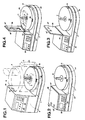
- Figure 1 is a perspective view of an appliance according to the invention and comprising a lateral boss and a receiving base of an accessory shown in broken lines
- Figure 2 is a perspective view of a variant of a household appliance according to the invention and comprising a small boss equipped with a movable panel illustrated in the folded position on the boss
- Figure 3 is a view similar to Figure 2, but with the movable panel erected in the working position
- Figure 4 is a perspective view of a variant of the device of Figure 2 in which the movable panel is foldable on the base
- Figure 5 is a partial vertical section on a large scale of the housing and a cover illustrating the arrangement of the means of presence and identification of the cover on the bowl
- Figure 6 shows in perspective on a smaller scale a bowl and an accessory cover according to the invention
- Figure 7 shows a juicer accessory according to the invention
- FIG. 8 represents a fruit centrifuge accessory according to the invention.
- the household appliance with multiple functions for processing food comprises a housing 1 having the general shape of an L consisting of a base 2 and a lateral boss 2 'extending in height over almost the entire height of the accessory.
- the base 2 is intended to receive various accessories comprising a bowl 3 equipped with a cover 4 and in which rotates a working tool which can be for example: a chopper knife 5, a vegetable cutter (not shown), a fruit press with rotary cone 6 and grid 7 forming a cover (FIG. 7), and a fruit centrifuge with rotary basket 8 (FIG. 8).
- a working tool which can be for example: a chopper knife 5, a vegetable cutter (not shown), a fruit press with rotary cone 6 and grid 7 forming a cover (FIG. 7), and a fruit centrifuge with rotary basket 8 (FIG. 8).
- the working tool is driven through a hole 9 made in the bottom 10 of the bowl by the output shaft 11 of a motor unit (not shown) arranged in the housing.
- the household appliance also comprises an electrical device for controlling the supply of the motor comprising means for detecting the presence of the cover 4 on the bowl 3 and capable of causing said device to take an active state of authorization to start the motor when the cover 4 is brought into its correct position for closing the bowl 3, as well as a speed variator (not shown) intended to adapt the speed of the output shaft 11 according to the tool used.
- an electrical device for controlling the supply of the motor comprising means for detecting the presence of the cover 4 on the bowl 3 and capable of causing said device to take an active state of authorization to start the motor when the cover 4 is brought into its correct position for closing the bowl 3, as well as a speed variator (not shown) intended to adapt the speed of the output shaft 11 according to the tool used.
- the electrical device for controlling the supply of the motor further comprises a means for detecting the presence and correct positioning of the bowl 3 on the base 2, as well as means for identifying the various covers. 4 which are associated with the means for detecting the presence of the cover on the bowl and which are adapted to control the speed controller in order to associate with each cover 4 a determined speed of the tool.
- the means for detecting the presence of the bowl and for detecting the presence of the cover as well as the means for identifying the cover comprise, on the one hand, sensors 12, 13 and 14 arranged in the housing, and on the other hand , remote actuators 15, 16, 17, 18 and 19 respectively arranged in the bowl and in the cover.
- Each sensor is made up of a HALL effect element, while each remote actuator is made up of a magnetic element, such as for example a magnetized metal plate or a ferrite magnet whose flux will control the HALL effect sensor.
- the actuator (s) 15, 16, 17, 18, 19 can be embedded in said plastic (see FIG. 5).
- the sensor 12 for the presence of the bowl, and the actuator 15 are arranged respectively in the base 2 and in the bottom region 10 of the bowl. 3, while the sensors 13, 14, and the corresponding presence and identification actuators 16, 17, 18 and 19 of the cover 4 are arranged respectively in the boss 2 'and in the cover 4 so as to be located opposite each other when the lid is brought into its correct closed bowl position, illustrated diagrammatically in FIG. 1.
- the invention provides, to perform the functions mentioned in this Application, to use only three HALL effect sensors, a magnet 15 on the bowl 3 and a 16 or 17 or two 18 and 19 magnets on the covers 4. To take account of the small height given to the covers, the sensors 13 and 14 and magnets 16, 17, 18 and 19 relating to the covers will be angularly spaced and located practically in the same horizontal plane.
- the cover 4 of the accessory of FIG. 6 comprises a single magnet 16 which, for the correct position for closing said cover, comes opposite the sensor 13.
- the cover grid 7 of the citrus juicer of FIG. 7 also includes a single magnet 17 angularly offset so that, when this cover grid 7 occupies its correct operating position corresponding to the superimposition of the handles 20 of the cover and 21 of the bowl, said magnet comes opposite the sensor 14.
- the cover 4 comprises two magnets 18 and 19 spaced apart and oriented respectively according to the same angular references as those of the magnets 16 and 17.
- the sensors are connected to an electronic signal processing device 22 comprising a multiplexer stage with three inputs and whose outputs are connected to a digital potentiometer, itself connected to an integrated circuit, the output signals of which will trigger or not the active state of the motor power control device as well as the control of the variable speed drive.
- This variable speed drive comprises, in a manner known per se, a TRIAC mounted in series with the motor and the trigger of which receives the control signals emitted by said integrated circuit.
- the housing 1 ′ has a small boss 23 located laterally at the base 24, equipped with a movable panel 25 or 26 mounted articulated around a horizontal axis 27 arranged on the side face of the small boss facing the base, the sensors presence and identification of the cover 13 ′, 14 ′ being arranged on said panel 25 or 26 in a region such that when the panel is raised vertically (FIGS. 3 and 4) said sensors are located opposite actuator (s) 16, 17, 18 and 19 of the bowl lid.
- the panels 25 and 26 are folded down respectively on the boss 23 and on the base 24.
- the bowl 3 is placed on the base 2 and it is brought into its correct position, determined by mutual means of indexing 28, so as to place the magnet 15 opposite the sensor 12
- the cover 4 on the bowl 3 and bring it, for example by means of a locking device by rotation of the bayonet type, in its correct closed position so that the magnet 16 is located opposite the sensor 13.
- the signals then transmitted by the sensor 13 are processed by the electronic device 22 so as to make the control device take the active state. motor supply and to adjust the speed controller to a value determined for this accessory, i.e.
- the user triggers the preselected operation of the device by means of a general switch 30.
- the grid 7 forming the cover will be placed in the correct position so as to bring the magnet 17 opposite of the sensor 14, and the detection of the presence of the grid and the adjustment of the speed controller to a minimum value will be obtained in the same manner as above.
Description
La présente invention concerne un appareil électroménager à fonctions multiples pour le traitement des aliments et comprenant un boîtier dont une région formant embase est destinée à recevoir divers accessoires comportant un bol équipé d'un couvercle, et dans lequel tourne un outil de travail qui peut être, par exemple, un hachoir, un coupe-légumes, une centrifugeuse à fruits et qui est entraîné, à travers un trou pratiqué dans le fond du bol, par l'arbre de sortie d'un groupe moteur, ainsi qu'un dispositif électrique de commande de l'alimentation du moteur comportant un moyen de détection de la présence du couvercle sur le bol et susceptible de faire prendre audit dispositif un état actif d'autorisation de mise en marche du moteur lorsque le couvercle est amené en sa position correcte de fermeture du bol, ainsi qu'un variateur de vitesse destiné à adapter la vitesse de l'arbre de sortie en fonction de l'outil utilisé.The present invention relates to a household appliance with multiple functions for processing food and comprising a housing of which a base region is intended to receive various accessories comprising a bowl equipped with a lid, and in which rotates a working tool which can be , for example, a chopper, a vegetable cutter, a fruit centrifuge and which is driven, through a hole in the bottom of the bowl, by the output shaft of a motor unit, as well as an electrical device motor power control device comprising means for detecting the presence of the cover on the bowl and capable of causing said device to take an active state of authorization to start the engine when the cover is brought into its correct position closing of the bowl, as well as a speed variator intended to adapt the speed of the output shaft according to the tool used.
Un tel appareil électroménager à fonctions multiples est connu du document US-A-4 174 073. Toutefois, avec cet appareil, d'une part, la sécurité d'utilisation n'est pas absolues, car un enfant peut, en l'absence du bol sur l'embase, mettre l'appareil en marche au moyen du couvercle seul, et d'autre part, l'usager doit, à chaque changement d'accessoire, veiller à régler correctement la vitesse pour accomplir de façon satisfaisante la fonction choisie.Such a multifunction appliance is known from document US-A-4 174 073. However, with this appliance, on the one hand, the safety of use is not absolute, because a child can, in the absence from the bowl to the base, switch on the device by means of the cover alone, and on the other hand, the user must, at each change of accessory, take care to set the speed correctly to perform the function satisfactorily chosen.
Le document FR-A-2 483 697 décrit un appareil électroménager à fonctions multiples dans lequel le dispositif de verrouillage de sécurité du bol et de son couvercle fait intervenir des moyens de détection adaptés à couper l'alimentation du moteur d'entraînement de l'outil si le bol et le couvercle ne sont pas tous les deux dans leurs positions respectives correctes de verrouillage mécanique. Avec cet appareil, l'usager doit également, à chaque changement d'accessoire, veuiller à régler correctement la vitesse pour obtenir un fonctionnement satisfaisant de l'outil utilisé.The document FR-A-2 483 697 describes a household appliance with multiple functions in which the safety locking device of the bowl and of its cover involves detection means adapted to cut off the power supply to the drive motor of the tool if the bowl and the lid are not both in their respective correct mechanical locking positions. With this device, the user must also, at each change of accessory, make sure to correctly adjust the speed to obtain satisfactory operation of the tool used.
Par ailleurs, il est connu d'après le document EP-A-120 496 relatif à un appareil électroménager destiné à recevoir divers outils de travail, de prévoir une adaptation de la vitesse du moteur d'entraînement en fonction de l'outil utilisé.Furthermore, it is known from document EP-A-120 496 relating to a household appliance intended to receive various working tools, to provide an adaptation of the speed of the drive motor according to the tool used.
L'invention a pour but de réaliser un appareil électroménager à fonctions multiples pour le traitement des aliments, qui procure à la fois une sécurité d'utilisation absolue et un réglage automatique de la vitesse de son moteur en fonction de l'accessoire utilisé.The object of the invention is to provide a household appliance with multiple functions for processing food, which provides both absolute safety in use and automatic adjustment of the speed of its motor as a function of the accessory used.
Selon l'invention, un appareil électroménager à fonctions multiples du type décrit précédemment, est plus particulièrement caractérisé en ce que le dispositif électrique de commande de l'alimentation du moteur comprend, en outre, un moyen de détection de la présence et du positionnement correct du bol sur l'embase, ainsi que des moyens d'identification des différents couvercles qui sont associés au moyen de détection de la présence du couvercle sur le bol et qui sont adaptés à commander le variateur de vitesse afin d'associer à chaque couvercle une vitesse déterminée de l'outil.According to the invention, a household appliance with multiple functions of the type described above, is more particularly characterized in that the electrical device for controlling the supply of the motor further comprises means for detecting the presence and correct positioning of the bowl on the base, as well as means for identifying the various covers which are associated with the means for detecting the presence of the cover on the bowl and which are suitable for controlling the variable speed drive in order to associate with each cover a determined tool speed.
Grâce à ces nouveaux moyens de détection du bol et d'identification des accessoires, on comprendra que l'on obtient une sécurité d'utilisation absolue, et un fonctionnement automatique de l'appareil.Thanks to these new means of detecting the bowl and identifying the accessories, it will be understood that absolute security of use is obtained, and automatic operation of the device.
Plusieurs modifications de l'appareil selon la revendication principale sont définies dans les revendications dépendantesSeveral modifications of the apparatus according to the main claim are defined in the dependent claims
Les caractéristiques et avantages de l'invention ressortiront d'ailleurs de la description qui va suivre, à titre d'exemple, en référence aux dessins annexés dans lesquels :
la figure 1 est une vue en perspective d'un appareil électroménager selon l'invention et comportant un bossage latéral et une embase de réception d'un accessoire représenté en traits interrompus ; la figure 2 est une vue en perspective d'une variante d'un appareil électroménager selon l'invention et comportant un petit bossage équipé d'un panneau mobile illustré en position rabattue sur le bossage ; la figure 3 est une vue analogue à la figure 2, mais avec le panneau mobile dressé en position de travail ; la figure 4 est une vue en perspective d'une variante de l'appareil de la figure 2 dans laquelle le panneau mobile est rabattable sur l'embase ; la figure 5 est une coupe verticale partielle à grande échelle du boîtier et d'un couvercle illustrant l'agencement des moyens de présence et d'identification du couvercle sur le bol ; la figure 6 représente en perspective à plus petite échelle un bol et un couvercle d'accessoire selon l'invention ; la figure 7 représente un accessoire presse-agrumes selon l'invention ; la figure 8 représente un accessoire centrifugeuse à fruits selon l'invention.The characteristics and advantages of the invention will become apparent from the description which follows, by way of example, with reference to the appended drawings in which:
Figure 1 is a perspective view of an appliance according to the invention and comprising a lateral boss and a receiving base of an accessory shown in broken lines; Figure 2 is a perspective view of a variant of a household appliance according to the invention and comprising a small boss equipped with a movable panel illustrated in the folded position on the boss; Figure 3 is a view similar to Figure 2, but with the movable panel erected in the working position; Figure 4 is a perspective view of a variant of the device of Figure 2 in which the movable panel is foldable on the base; Figure 5 is a partial vertical section on a large scale of the housing and a cover illustrating the arrangement of the means of presence and identification of the cover on the bowl; Figure 6 shows in perspective on a smaller scale a bowl and an accessory cover according to the invention; Figure 7 shows a juicer accessory according to the invention; FIG. 8 represents a fruit centrifuge accessory according to the invention.
Comme représenté à la figure 1, l'appareil électroménager à fonctions multiples pour le traitement des aliments comprend un boîtier 1 présentant la forme générale d'un L constituée d'une embase 2 et d'un bossage latéral 2' s'étendant en hauteur sur pratiquement toute la hauteur de l'accessoire.As shown in Figure 1, the household appliance with multiple functions for processing food comprises a
L'embase 2 est destinée à recevoir divers accessoires comportant un bol 3 équipé d'un couvercle 4 et dans lequel tourne un outil de travail qui peut être par exemple : un couteau-hachoir 5, un coupe-légumes (non représenté), un presse-fruits à cône rotatif 6 et grille 7 formant couvercle (figure 7), et une centrifugeuse à fruits à panier rotatif 8 (figure 8). L'outil de travail est entraîné à travers un trou 9 pratiqué dans le fond 10 du bol par l'arbre de sortie 11 d'un groupe moteur (non représenté) agencé dans le boîtier.The
L'appareil électroménager comporte également un dispositif électrique de commande de l'alimentation du moteur comportant un moyen de détection de la présence du couvercle 4 sur le bol 3 et susceptible de faire prendre audit dispositif un état actif d'autorisation de mise en marche du moteur lorsque le couvercle 4 est amené en sa position correcte de fermeture du bol 3, ainsi qu'un variateur de vitesse (non représenté) destiné à adapter la vitesse de l'arbre de sortie 11 en fonction de l'outil utilisé.The household appliance also comprises an electrical device for controlling the supply of the motor comprising means for detecting the presence of the cover 4 on the
Selon l'invention le dispositif électrique de commande de l'alimentation du moteur comprend, en outre, un moyen de détection de la présence et du positionnement correct du bol 3 sur l'embase 2, ainsi que des moyens d'identification des différents couvercles 4 qui sont associés au moyen de détection de la présence du couvercle sur le bol et qui sont adaptés à commander le variateur de vitesse afin d'associer à chaque couvercle 4 une vitesse déterminée de l'outil.According to the invention, the electrical device for controlling the supply of the motor further comprises a means for detecting the presence and correct positioning of the
Les moyens de détection de la présence du bol et de détection de la présence du couvercle ainsi que les moyens d'identification du couvercle comportent, d'une part, des capteurs 12, 13 et 14 agencés dans le boîtier, et d'autre part, des actionneurs à distance 15, 16, 17, 18 et 19 agencés respectivement dans le bol et dans le couvercle.The means for detecting the presence of the bowl and for detecting the presence of the cover as well as the means for identifying the cover comprise, on the one hand,
Chaque capteur est constitué d'un élément à effet HALL, tandis que chaque actionneur à distance est constitué par un élément magnétique, tel que par exemple une plaquette métallique aimantée ou un aimant ferrite dont le flux va commander le capteur à effet HALL.Each sensor is made up of a HALL effect element, while each remote actuator is made up of a magnetic element, such as for example a magnetized metal plate or a ferrite magnet whose flux will control the HALL effect sensor.
Comme le bol 3 et le couvercle 4 sont réalisés en matière plastique, le ou les actionneurs 15, 16, 17, 18, 19 peuvent être noyés dans ladite matière plastique (voir figure 5).As the
Afin d'obtenir le fonctionnement correct et éviter le plus possible l'atténuation du flux magnétique, le capteur 12 de la présence du bol, et l'actionneur 15 sont agencés respectivement dans l'embase 2 et dans la région de fond 10 du bol 3, tandis que les capteurs 13, 14, et les actionneurs correspondants de présence et d'identification 16, 17, 18 et 19 du couvercle 4 sont agencés respectivement dans le bossage 2' et dans le couvercle 4 de manière à être situés en regard les uns les autres lorsque le couvercle est amené en sa position correcte de fermeture du bol, illustrée schématiquement sur la figure 1.In order to obtain correct operation and avoid as much as possible the attenuation of the magnetic flux, the
Afin de réduire le coût de l'appareil, l'invention prévoit, pour accomplir les fonctions citées dans la présente Demande, d'utiliser seulement trois capteurs à effet HALL, un aimant 15 sur le bol 3 et un 16 ou 17 ou deux 18 et 19 aimants sur les couvercles 4. Pour tenir compte de la faible hauteur donnée aux couvercles, les capteurs 13 et 14 et aimants 16, 17, 18 et 19 se rapportant aux couvercles seront angulairement espacés et situés pratiquement dans un même plan horizontal.In order to reduce the cost of the device, the invention provides, to perform the functions mentioned in this Application, to use only three HALL effect sensors, a
Ainsi, le couvercle 4 de l'accessoire de la figure 6 comporte un seul aimant 16 qui pour la position correcte de fermeture dudit couvercle vient en regard du capteur 13. La grille couvercle 7 du presse-agrumes de la figure 7 comporte également un seul aimant 17 décalé angulairement de manière que, lorsque cette grille couvercle 7 occupe sa position correcte de fonctionnement correspondant à la superposition des poignées 20 du couvercle et 21 du bol, ledit aimant vient en regard du capteur 14. Quant à l'accessoire centrifugeuse de la figure 8, le couvercle 4 comporte deux aimants 18 et 19 espacés et orientés respectivement selon les mêmes références angulaires que celles des aimants 16 et 17.Thus, the cover 4 of the accessory of FIG. 6 comprises a
Par conséquent, pour obtenir à la fois la détection de la présence du bol et des couvercles, ainsi que l'identification desdits couvercles, les capteurs sont reliés à un dispositif électronique de traitement des signaux 22 comportant un étage multiplexeur à trois entrées et dont les sorties sont reliées à un potentiomètre numérique, lui-même relié à un circuit intégré dont les signaux de sortie vont déclencher ou non l'état actif du dispositif de commande de l'alimentation du moteur ainsi que la commande du variateur de vitesse. Ce variateur de vitesse comporte de façon connue en soi un TRIAC monté en série avec le moteur et dont la gâchette reçoit les signaux de commande émis par ledit circuit intégré.Consequently, in order to obtain both the detection of the presence of the bowl and of the covers, as well as the identification of said covers, the sensors are connected to an electronic signal processing device 22 comprising a multiplexer stage with three inputs and whose outputs are connected to a digital potentiometer, itself connected to an integrated circuit, the output signals of which will trigger or not the active state of the motor power control device as well as the control of the variable speed drive. This variable speed drive comprises, in a manner known per se, a TRIAC mounted in series with the motor and the trigger of which receives the control signals emitted by said integrated circuit.
Selon les variantes illustrées aux figures 2, 3, et 4 le boîtier 1' présente un petit bossage 23 situé latéralement à l'embase 24, équipé d'un panneau mobile 25 ou 26 monté articulé autour d'un axe horizontal 27 agencé sur la face latérale du petit bossage tournée vers l'embase, les capteurs de présence et d'identification du couvercle 13', 14' étant agencés sur ledit panneau 25 ou 26 dans une région telle que lorsque le panneau est dressé verticalement (figure 3 et 4) lesdits capteurs sont situés en regard du ou des actionneurs 16, 17, 18 et 19 du couvercle du bol. Pour la position de rangement, les panneaux 25 et 26 sont rabattus respectivement sur le bossage 23 et sur l'embase 24.According to the variants illustrated in Figures 2, 3, and 4 the
On va décrire ci-après le fonctionnement de l'appareil avec différents accessoires.The operation of the device with various accessories will be described below.
Dans le cas où l'on utilise l'accessoire de la figure 6 équipé par exemple du couteau 5, ont vient placer le bol 3 sur l'embase 2 et on l'amène en sa position correcte, déterminée par des moyens mutuels d'indexation 28, de manière à placer l'aimant 15 en regard du capteur 12 Puis on place le couvercle 4 sur le bol 3 et on l'amène, par exemple au moyen d'un dispositif de verrouillage par rotation du type à baïonnette, en sa position correcte de fermeture de sorte que l'aimant 16 soit situé en regard du capteur 13. Les signaux émis alors par le capteur 13 sont traités par le dispositif électronique 22 de manière à faire prendre l'état actif au dispositif de commande de l'alimentation du moteur et à ajuster le variateur de vitesse à une valeur déterminée pour cet accessoire, c'est à dire dans ce cas une plage de valeurs allant du minimum au maximum et qui peuvent être incrémentées ou décrémentées par l'usager au moyen d'un clavier de commande 29. Par mesure de sécurité supplémentaire, l'usager déclenche le fonctionnement présélectionné de l'appareil au moyen d'un interrupteur général 30.In the case where the accessory of FIG. 6 is used, equipped for example with the knife 5, the
Dans le cas où l'on utilise l'accessoire presse-agrumes de la figure 7, la grille 7 formant le couvercle sera mise en position correcte de manière à amener l'aimant 17 en regard du capteur 14, et l'on obtiendra de la même manière que ci-dessus la détection de la présence de la grille et l'ajustement du variateur de vitesse à une valeur minimum.In the case where the citrus press accessory of FIG. 7 is used, the grid 7 forming the cover will be placed in the correct position so as to bring the
Dans le cas où l'on utilise l'accessoire centrifugeuse de la figure 8, on comprendra que du fait que le couvercle porte deux aimants 18 et 19, les deux capteurs 13 et 14 sont influencés et l'on obtiendra, grâce au multiplexeur, également la détection de la présence du couvercle et l'ajustement automatique du variateur de vitesse à une vitesse maximum.In the case where the centrifuge accessory of FIG. 8 is used, it will be understood that because the cover carries two
Claims (7)
- An electrical household appliance having multiple functions for the processing of food and comprising a housing (1, 1'), one region of which forming a base (2, 2') is intended to receive various attachments comprising a bowl (3) equipped with a lid (4), and in which a work tool (5, 6, 8) rotates, which may be, for example, a chopping blade, a vegetable blade, a juice extractor and which is driven, through a hole (9) provided in the base (10) of the bowl, by the driven spindle (11) of a motor unit, and also an electrical device-for controlling the power supply of the motor comprising a means for detecting the presence of the lid (4) on the bowl (3) and capable of making the said device assume an active state for enabling the start-up of the motor when the lid is brought into its correct bowl-closing position, and also a variable speed drive intended to adapt the speed of the driven spindle as a function of the tool used,
characterised in that the electrical device for controlling the power supply of the motor also comprises a means for detecting the presence and the correct position of the bowl (3) on the base (2, 2'), as well as means for identifying the different lids (4) which are associated with the means for detecting the presence of the lid on the bowl and which are adapted to control the variable speed drive in order to associate with each lid (4) a determined speed of the tool (5, 6, 8). - An electrical household appliance according to Claim 1,
characterised in that the means for detecting the presence of the bowl (3) and detecting the presence of the lid (4) and also the means for identifying the lid (4) comprise, firstly, sensors (12, 13, 14) disposed in the housing, and secondly long-distance actuators (15-16, 17, 18, 19) disposed in the bowl (3) and in the lid (4). - An electrical household appliance according to Claim 2,
characterised in that each sensor (12, 13, 14) is formed by a HALL element, whereas each long-distance actuator (15-16, 17, 18, 19) is formed by a magnetic element. - An electrical household appliance according to Claim 3,
characterised in that the housing (1) having a general L shape formed by the base (2) and a lateral projection (2') extending in height over practically the entire height of the attachment, the sensor (12) of the presence of the bowl (3), and the corresponding actuator (15) are disposed respectively in the base (2) and in the bottom region (10) of the bowl, whereas the sensors(s) (13, 14) and the corresponding presence and identification actuators(s) (16, 17, 18, 19) of the lid (4) are disposed respectively in the projection (2') and in the lid (4) so as to be situated opposite one another when the lid (4) is brought into its correct bowl (3) closing position. - An electrical household appliance according to Claim 3,
characterised in that the housing (1') has a small projection (23) situated to the side of the base (24), equipped with a mobile panel (25 - 26) mounted in articulated fashion around a horizontal axis (27) disposed on the lateral face of the small projection turned towards the base, the presence and identification sensor(s) (13', 14') of the lid (4) being disposed on said panel in a region so that when the panel is raised vertically, the sensor(s) is(are) situated opposite the actuator(s) (16, 17, 18, 19) of the lid of the bowl. - An electrical household appliance according to any one of Claims 3 to 5,
characterised in that as the bowl (3) and the lid (4) are made of plastic, the actuators(s) (15 - 16, 17, 18, 19) are embedded in the said plastic material. - An electrical household appliance according to any one of Claims 3 to 6,
characterised in that the HALL sensors (12 - 13, 14) are connected to an electronic device (22) for processing the signals comprising a stage multiplexer, the outputs of which are connected to a numerical potentiometer, itself connected to an integrated circuit, the output signals of which will trigger or not the active state of the device for controlling the power supply of the motor, as well as the control of the variable speed drive.
Applications Claiming Priority (2)
| Application Number | Priority Date | Filing Date | Title |
|---|---|---|---|
| FR9000930 | 1990-01-26 | ||
| FR9000930A FR2657518B1 (en) | 1990-01-26 | 1990-01-26 | MULTIPURPOSE HOUSEHOLD APPLIANCES FOR PROCESSING FOOD. |
Publications (2)
| Publication Number | Publication Date |
|---|---|
| EP0440051A1 EP0440051A1 (en) | 1991-08-07 |
| EP0440051B1 true EP0440051B1 (en) | 1994-03-23 |
Family
ID=9393144
Family Applications (1)
| Application Number | Title | Priority Date | Filing Date |
|---|---|---|---|
| EP91100554A Expired - Lifetime EP0440051B1 (en) | 1990-01-26 | 1991-01-18 | Domestic food processor with multiple functions |
Country Status (11)
| Country | Link |
|---|---|
| US (1) | US5071077A (en) |
| EP (1) | EP0440051B1 (en) |
| JP (1) | JPH04322619A (en) |
| KR (1) | KR0175671B1 (en) |
| BR (1) | BR9100323A (en) |
| CA (1) | CA2034751C (en) |
| DE (1) | DE69101451T2 (en) |
| ES (1) | ES2052284T3 (en) |
| FR (1) | FR2657518B1 (en) |
| MX (1) | MX173370B (en) |
| PT (1) | PT96566B (en) |
Cited By (2)
| Publication number | Priority date | Publication date | Assignee | Title |
|---|---|---|---|---|
| US9099939B2 (en) | 2011-07-25 | 2015-08-04 | Braun Gmbh | Linear electro-polymer motors and devices having the same |
| US9226808B2 (en) | 2011-07-25 | 2016-01-05 | Braun Gmbh | Attachment section for an oral hygiene device |
Families Citing this family (66)
| Publication number | Priority date | Publication date | Assignee | Title |
|---|---|---|---|---|
| EP0546208A1 (en) * | 1991-12-11 | 1993-06-16 | MASCHINENFABRIK KURT NEUBAUER GmbH & Co. | Deep-fat fryer |
| FR2692677B1 (en) * | 1992-06-22 | 1997-12-26 | Moulinex Sa | SENSOR DETECTION SYSTEM AND METHOD FOR IMPLEMENTING A DEVICE FOR VERIFYING THE OPERATION OF THIS DETECTION SYSTEM. |
| US5348393A (en) * | 1992-07-24 | 1994-09-20 | Univex Corporation | Safety guard system for food mixer |
| US5380086A (en) * | 1992-08-27 | 1995-01-10 | K-Tec, Inc. | Multipurpose food mixing appliance specially adapted for kneading dough |
| EP0589093A1 (en) * | 1992-09-22 | 1994-03-30 | Sigma-Delta N.V. | Kitchen robot with smart mixing arm |
| BE1007431A3 (en) * | 1993-08-04 | 1995-06-13 | Philips Electronics Nv | Food with a lid lock with centrifugal organ. |
| DE4422086C1 (en) * | 1994-06-24 | 1995-09-21 | Braun Ag | Electric food processor with interchangeable tools |
| GB2305598A (en) * | 1995-09-19 | 1997-04-16 | Kenwood Marks Ltd | Food processor |
| FR2753621B1 (en) * | 1996-09-20 | 1998-12-18 | HOUSEHOLD APPLIANCE FOR THE TREATMENT OF FOOD COMPRISING A WORK TOOL STORAGE DEVICE | |
| DE19639582C2 (en) * | 1996-09-26 | 1998-10-01 | Braun Ag | Food processor |
| US5669289A (en) * | 1996-12-30 | 1997-09-23 | Chen; Tse-Hsiung | Strainer assembly |
| SE514114C2 (en) * | 1997-06-26 | 2001-01-08 | Haellde Maskiner Ab | Device for cutting machines for food preparation |
| KR200258626Y1 (en) * | 1999-06-30 | 2001-12-28 | 윤청목 | Mixer combined with Juice Extractor |
| US6446547B2 (en) | 1999-12-29 | 2002-09-10 | Conair Corporation | Food processing appliance |
| US7086111B2 (en) | 2001-03-16 | 2006-08-08 | Braun Gmbh | Electric dental cleaning device |
| WO2002017761A1 (en) * | 2000-08-31 | 2002-03-07 | Koninklijke Philips Electronics N.V. | Kitchen appliance having a removable container and protection means |
| WO2002021986A1 (en) * | 2000-09-13 | 2002-03-21 | Hamilton Beach/Proctor-Silex, Inc. | Food processing machine |
| EP1286615A2 (en) * | 2000-11-29 | 2003-03-05 | Koninklijke Philips Electronics N.V. | Kitchen appliance |
| KR100735645B1 (en) | 2001-03-14 | 2007-07-06 | 브라운 게엠베하 | Method and device for cleaning teeth |
| DE10159395B4 (en) | 2001-12-04 | 2010-11-11 | Braun Gmbh | Device for cleaning teeth |
| US6609821B2 (en) | 2001-04-13 | 2003-08-26 | Sunbeam Products, Inc. | Blender base with food processor capabilities |
| DE102005040513A1 (en) * | 2005-08-26 | 2007-03-01 | BSH Bosch und Siemens Hausgeräte GmbH | Kitchen appliance with a magnetic safety lock |
| DE102005040525A1 (en) * | 2005-08-26 | 2007-03-01 | BSH Bosch und Siemens Hausgeräte GmbH | Kitchen appliance with safety system and method for operating a kitchen appliance |
| FR2892613B1 (en) * | 2005-11-03 | 2008-02-15 | Electrolux Professionnel Soc P | ELECTRIC FOOD PROCESSING APPARATUS HAVING AUTOMATIC SPEED ADJUSTING MEANS AND TOOL FOR SUCH AN APPARATUS. |
| WO2008077124A2 (en) * | 2006-12-19 | 2008-06-26 | Conair Corporation | Food processor |
| US7950842B2 (en) | 2007-03-05 | 2011-05-31 | Hamilton Beach Brands, Inc. | Durability monitoring and improvement of a blender |
| US20090200408A1 (en) * | 2007-08-17 | 2009-08-13 | Little Caesar Enterprises, Inc. | Automated Cheese Shredder For Applying Cheese To Pizza |
| US20090080285A1 (en) * | 2007-09-26 | 2009-03-26 | Proteus Design, Inc. | Processor |
| DE102007050858A1 (en) * | 2007-10-24 | 2009-04-30 | Weber Maschinenbau Gmbh Breidenbach | Device for slicing a food product |
| ES2319085B1 (en) * | 2008-10-23 | 2010-03-16 | Electrodomesticos Taurus, S.L. | PICADOR ACCESSORY FOR FOOD PROCESSOR. |
| US20100308142A1 (en) * | 2009-06-08 | 2010-12-09 | Krasznai Charles Z | Magnetic switch for food processor |
| EP2547244B1 (en) * | 2010-03-18 | 2016-09-07 | Breville PTY Limited | Combination juicer-blender |
| US8720325B2 (en) | 2010-04-29 | 2014-05-13 | Whirlpool Corporation | Food processor with a lockable adjustable blade assembly |
| US10449685B2 (en) | 2010-04-29 | 2019-10-22 | Whirlpool Corporation | Food processor with adjustable blade assembly |
| DE102010021916B4 (en) * | 2010-05-28 | 2014-01-30 | BSH Bosch und Siemens Hausgeräte GmbH | Kitchen utensil with storage device |
| DE102011051149B4 (en) * | 2010-09-30 | 2019-09-12 | Vorwerk & Co. Interholding Gmbh | Electrically operated food processor with a cooking vessel |
| CA141000S (en) | 2010-12-20 | 2011-12-28 | Baby Bullet Llc | Kitchen food processor container |
| CA141001S (en) | 2010-12-20 | 2011-12-28 | Baby Bullet Llc | Food storage cup |
| ES2534822T3 (en) | 2011-07-25 | 2015-04-29 | Braun Gmbh | Oral hygiene device |
| US9808774B2 (en) | 2013-03-01 | 2017-11-07 | Whirlpool Corporation | Stirring wand |
| US20150059597A1 (en) * | 2013-08-30 | 2015-03-05 | E. Mishan & Sons, Inc. | Slow and Citrus Juicer Combination |
| AU2014101657B4 (en) * | 2013-09-26 | 2020-02-06 | Newell Australia Pty Ltd | Kitchen appliance |
| USD734637S1 (en) * | 2014-03-14 | 2015-07-21 | Whirlpool Corporation | Appliance base |
| US9049967B1 (en) | 2014-08-08 | 2015-06-09 | Euro-Pro Operating Llc | Food processing apparatus and method |
| DE102014111596A1 (en) * | 2014-08-13 | 2016-02-18 | Vorwerk & Co. Interholding Gmbh | kitchen appliance |
| USD757485S1 (en) * | 2014-09-09 | 2016-05-31 | Whirlpool Corporation | Cook processor assembly |
| USD758126S1 (en) * | 2014-09-09 | 2016-06-07 | Whirlpool Corporation | Cook processor |
| US10085599B2 (en) | 2014-12-19 | 2018-10-02 | Whirlpool Corporation | Multi-cook and food processing prep product |
| CN107533660B (en) * | 2015-03-06 | 2021-05-28 | 维他拌管理有限公司 | Mixing container identification system |
| JP6942638B2 (en) | 2015-06-08 | 2021-09-29 | シャークニンジャ オペレーティング エルエルシー | Food processing equipment and methods |
| WO2017001880A1 (en) | 2015-07-01 | 2017-01-05 | Nefzger Frank | Citrus juicer implement for kitchen appliances with cooking function |
| US10327595B2 (en) | 2016-03-23 | 2019-06-25 | Capbran Holdings, Llc | Food processor |
| US10610055B2 (en) * | 2016-09-21 | 2020-04-07 | Whirlpool Corporation | Food processor non-contact interlock |
| USD853782S1 (en) | 2017-02-20 | 2019-07-16 | Whirlpool Corporation | Food processor |
| US11039715B2 (en) * | 2017-07-05 | 2021-06-22 | Illinois Tool Works Inc. | Food processing machine adaptive to food load |
| AT520201B1 (en) * | 2017-08-10 | 2019-02-15 | Innerhuber Johann | METHOD FOR CONTROLLING A KITCHEN MACHINE |
| US11166592B2 (en) | 2017-09-25 | 2021-11-09 | Whirlpool Corporation | Food processor |
| WO2020002947A1 (en) * | 2018-06-29 | 2020-01-02 | Kenwood Limited | A food processing apparatus |
| GB2575254A (en) * | 2018-06-29 | 2020-01-08 | Kenwood Ltd | A food processing apparatus |
| DE102018217416A1 (en) * | 2018-10-11 | 2020-04-16 | BSH Hausgeräte GmbH | Kitchen appliance with adaptive setting of an operating parameter |
| USD896023S1 (en) * | 2020-05-27 | 2020-09-15 | Xiushan Ye | Food processor |
| CA200981S (en) * | 2020-07-08 | 2021-11-24 | Midea Group Co Ltd | Base for food processor |
| CN114246051B (en) * | 2020-09-25 | 2023-09-08 | 南京泉峰科技有限公司 | Mower and control method thereof |
| CN114521799A (en) * | 2020-11-23 | 2022-05-24 | 浙江绍兴苏泊尔生活电器有限公司 | Cooking appliance and control method and device thereof |
| KR20230017061A (en) * | 2021-07-27 | 2023-02-03 | 엘지전자 주식회사 | Blender |
| EP4241638A1 (en) * | 2022-03-07 | 2023-09-13 | Vorwerk & Co. Interholding GmbH | Container assembly for a kitchen appliance |
Family Cites Families (10)
| Publication number | Priority date | Publication date | Assignee | Title |
|---|---|---|---|---|
| US3611358A (en) * | 1968-01-22 | 1971-10-05 | Olivetti & Co Spa | Hall effect keyboard |
| CA1164319A (en) * | 1979-08-29 | 1984-03-27 | Marcel Goggiola | Magnetic safety device, inter alia for a food processor |
| US4741482A (en) * | 1979-08-29 | 1988-05-03 | Robot-Coupe S.A. | Magnetic safety switch device for food processor |
| US4371118A (en) * | 1980-06-02 | 1983-02-01 | Cuisinarts, Inc. | Magnetic safety interlock method and apparatus for food processor |
| NZ197654A (en) * | 1980-07-11 | 1985-05-31 | Sunbeam Corp | Driving unit for food processor |
| US4629131A (en) * | 1981-02-25 | 1986-12-16 | Cuisinarts, Inc. | Magnetic safety interlock for a food processor utilizing vertically oriented, quadrant coded magnets |
| US4506836A (en) * | 1982-12-20 | 1985-03-26 | Cuisinarts Research & Development, Inc. | Dual cover and feed tube protector actuation apparatus for a food processor |
| DE3311291A1 (en) * | 1983-03-28 | 1984-10-04 | Braun Ag, 6000 Frankfurt | MAGNETIC SAFETY DEVICE, ESPECIALLY FOR A KITCHEN EQUIPMENT |
| DE3408692A1 (en) * | 1984-03-09 | 1985-09-19 | Robert Krups Stiftung & Co KG, 5650 Solingen | ELECTRICALLY OPERATED DEVICE FOR THE PROCESSING AND PREPARATION OF FOODSTUFFS OF ALL TYPES |
| FR2610502B1 (en) * | 1987-02-11 | 1991-02-08 | Levi Mario | A DETECTION AND DISPLAY DEVICE FOR AN AUTOMATIC EXPRESS COFFEE MACHINE |
-
1990
- 1990-01-26 FR FR9000930A patent/FR2657518B1/en not_active Expired - Fee Related
-
1991
- 1991-01-15 US US07/642,237 patent/US5071077A/en not_active Expired - Lifetime
- 1991-01-16 JP JP3003220A patent/JPH04322619A/en active Pending
- 1991-01-18 DE DE69101451T patent/DE69101451T2/en not_active Expired - Fee Related
- 1991-01-18 ES ES91100554T patent/ES2052284T3/en not_active Expired - Lifetime
- 1991-01-18 EP EP91100554A patent/EP0440051B1/en not_active Expired - Lifetime
- 1991-01-22 CA CA002034751A patent/CA2034751C/en not_active Expired - Fee Related
- 1991-01-24 BR BR919100323A patent/BR9100323A/en not_active IP Right Cessation
- 1991-01-24 PT PT96566A patent/PT96566B/en not_active IP Right Cessation
- 1991-01-25 KR KR1019910001260A patent/KR0175671B1/en not_active IP Right Cessation
- 1991-01-25 MX MX024297A patent/MX173370B/en unknown
Cited By (2)
| Publication number | Priority date | Publication date | Assignee | Title |
|---|---|---|---|---|
| US9099939B2 (en) | 2011-07-25 | 2015-08-04 | Braun Gmbh | Linear electro-polymer motors and devices having the same |
| US9226808B2 (en) | 2011-07-25 | 2016-01-05 | Braun Gmbh | Attachment section for an oral hygiene device |
Also Published As
| Publication number | Publication date |
|---|---|
| MX173370B (en) | 1994-02-23 |
| FR2657518B1 (en) | 1993-12-03 |
| PT96566B (en) | 1998-07-31 |
| DE69101451D1 (en) | 1994-04-28 |
| CA2034751A1 (en) | 1991-07-27 |
| KR0175671B1 (en) | 1999-02-01 |
| ES2052284T3 (en) | 1994-07-01 |
| PT96566A (en) | 1991-10-15 |
| EP0440051A1 (en) | 1991-08-07 |
| KR910014083A (en) | 1991-08-31 |
| BR9100323A (en) | 1991-10-22 |
| FR2657518A1 (en) | 1991-08-02 |
| DE69101451T2 (en) | 1994-08-04 |
| US5071077A (en) | 1991-12-10 |
| CA2034751C (en) | 1999-02-16 |
| JPH04322619A (en) | 1992-11-12 |
Similar Documents
| Publication | Publication Date | Title |
|---|---|---|
| EP0440051B1 (en) | Domestic food processor with multiple functions | |
| EP0949878B1 (en) | Press for food products, such as fruits or vegetables, and kitchen robot comprising such a press | |
| EP3155940B1 (en) | Domestic cooking appliance | |
| EP0029991A2 (en) | Electrical cooking appliance | |
| EP0805641B1 (en) | Household appliance with a rotary cutter, such as a chopper | |
| FR2935868A1 (en) | ELECTRICAL SECTOR | |
| EP1782719B2 (en) | Electric device for treating food, having automatic means for adjusting the speed, and tool for such a device | |
| EP2074919B1 (en) | Electrical kitchen appliance comprising a casing with several driving means located on a supporting base | |
| EP3801159A1 (en) | Appliance for preparing and/or cooking food, such as a food processor with integrated weighing device | |
| EP2172143B1 (en) | Method for controlling the movement of a component of an electrical household appliance, in particular a control panel of a baking oven | |
| EP0584140A1 (en) | Food processor for grating foods | |
| FR2641458A1 (en) | Kitchen robot | |
| EP3995056A1 (en) | Electrical cooking appliance comprising a work tool | |
| FR2754166A1 (en) | Electronic control for portable electric appliances for food preparation | |
| FR2535598A1 (en) | Device forming an audible alarm which can be associated with a hermetically closed container equipped with a valve. | |
| BE898577A (en) | HOUSEHOLD APPLIANCE PROVIDED WITH A SAFETY DEVICE TO PREVENT UNSUITABLE ACCESS TO CUTTING BLADES AND SIMILAR TOOLS. | |
| FR2789283A3 (en) | Power changeover device for food processing equipment | |
| FR2847145A1 (en) | Accessory for the motor unit of a portable food mixer, uses bowl with support for cutter blades and cover for bowl that houses a speed reduction gear between mixer drive motor and cutter blades | |
| WO2022122919A1 (en) | Food-preparation device | |
| EP0903963B1 (en) | Microwave oven and method for automatically reheating a food product placed inside of it | |
| EP2975986A1 (en) | Food preparation appliance | |
| FR3094620A1 (en) | CITRUS PRESS ACCESSORY FOR CULINARY PREPARATION APPLIANCES | |
| FR2510383A1 (en) | Time switch arrangement for pressure cooker - has switch in series with heating coil, contained within vessel and actuated by pressure member | |
| FR2818527A1 (en) | Kitchen appliance such as mini-mincers or mini-grinders, has improved security feature that prevents motor operation when the casing is returned to its normal operating position | |
| FR3068874A1 (en) | CULINARY PREPARATION APPARATUS AND METHOD OF CONTROLLING THE SAME |
Legal Events
| Date | Code | Title | Description |
|---|---|---|---|
| PUAI | Public reference made under article 153(3) epc to a published international application that has entered the european phase |
Free format text: ORIGINAL CODE: 0009012 |
|
| AK | Designated contracting states |
Kind code of ref document: A1 Designated state(s): CH DE ES GB IT LI NL SE |
|
| 17P | Request for examination filed |
Effective date: 19910618 |
|
| 17Q | First examination report despatched |
Effective date: 19930301 |
|
| GRAA | (expected) grant |
Free format text: ORIGINAL CODE: 0009210 |
|
| AK | Designated contracting states |
Kind code of ref document: B1 Designated state(s): CH DE ES GB IT LI NL SE |
|
| REF | Corresponds to: |
Ref document number: 69101451 Country of ref document: DE Date of ref document: 19940428 |
|
| GBT | Gb: translation of ep patent filed (gb section 77(6)(a)/1977) |
Effective date: 19940418 |
|
| ITF | It: translation for a ep patent filed |
Owner name: FUMERO BREVETTI S.N.C. |
|
| REG | Reference to a national code |
Ref country code: ES Ref legal event code: FG2A Ref document number: 2052284 Country of ref document: ES Kind code of ref document: T3 |
|
| PLBE | No opposition filed within time limit |
Free format text: ORIGINAL CODE: 0009261 |
|
| STAA | Information on the status of an ep patent application or granted ep patent |
Free format text: STATUS: NO OPPOSITION FILED WITHIN TIME LIMIT |
|
| EAL | Se: european patent in force in sweden |
Ref document number: 91100554.4 |
|
| 26N | No opposition filed | ||
| PGFP | Annual fee paid to national office [announced via postgrant information from national office to epo] |
Ref country code: CH Payment date: 20010130 Year of fee payment: 11 |
|
| PGFP | Annual fee paid to national office [announced via postgrant information from national office to epo] |
Ref country code: NL Payment date: 20010131 Year of fee payment: 11 |
|
| REG | Reference to a national code |
Ref country code: GB Ref legal event code: IF02 |
|
| PGFP | Annual fee paid to national office [announced via postgrant information from national office to epo] |
Ref country code: GB Payment date: 20020116 Year of fee payment: 12 |
|
| PGFP | Annual fee paid to national office [announced via postgrant information from national office to epo] |
Ref country code: SE Payment date: 20020125 Year of fee payment: 12 |
|
| PGFP | Annual fee paid to national office [announced via postgrant information from national office to epo] |
Ref country code: DE Payment date: 20020129 Year of fee payment: 12 |
|
| PG25 | Lapsed in a contracting state [announced via postgrant information from national office to epo] |
Ref country code: LI Free format text: LAPSE BECAUSE OF NON-PAYMENT OF DUE FEES Effective date: 20020131 Ref country code: CH Free format text: LAPSE BECAUSE OF NON-PAYMENT OF DUE FEES Effective date: 20020131 |
|
| PG25 | Lapsed in a contracting state [announced via postgrant information from national office to epo] |
Ref country code: NL Free format text: LAPSE BECAUSE OF NON-PAYMENT OF DUE FEES Effective date: 20020801 |
|
| REG | Reference to a national code |
Ref country code: CH Ref legal event code: PL |
|
| NLV4 | Nl: lapsed or anulled due to non-payment of the annual fee |
Effective date: 20020801 |
|
| PG25 | Lapsed in a contracting state [announced via postgrant information from national office to epo] |
Ref country code: GB Free format text: LAPSE BECAUSE OF NON-PAYMENT OF DUE FEES Effective date: 20030118 |
|
| PG25 | Lapsed in a contracting state [announced via postgrant information from national office to epo] |
Ref country code: SE Free format text: LAPSE BECAUSE OF NON-PAYMENT OF DUE FEES Effective date: 20030119 |
|
| PG25 | Lapsed in a contracting state [announced via postgrant information from national office to epo] |
Ref country code: DE Free format text: LAPSE BECAUSE OF NON-PAYMENT OF DUE FEES Effective date: 20030801 |
|
| EUG | Se: european patent has lapsed | ||
| GBPC | Gb: european patent ceased through non-payment of renewal fee | ||
| REG | Reference to a national code |
Ref country code: ES Ref legal event code: PC2A |
|
| PG25 | Lapsed in a contracting state [announced via postgrant information from national office to epo] |
Ref country code: IT Free format text: LAPSE BECAUSE OF NON-PAYMENT OF DUE FEES;WARNING: LAPSES OF ITALIAN PATENTS WITH EFFECTIVE DATE BEFORE 2007 MAY HAVE OCCURRED AT ANY TIME BEFORE 2007. THE CORRECT EFFECTIVE DATE MAY BE DIFFERENT FROM THE ONE RECORDED. Effective date: 20050118 |
|
| PGFP | Annual fee paid to national office [announced via postgrant information from national office to epo] |
Ref country code: ES Payment date: 20060103 Year of fee payment: 16 |
|
| REG | Reference to a national code |
Ref country code: ES Ref legal event code: FD2A Effective date: 20070119 |
|
| PG25 | Lapsed in a contracting state [announced via postgrant information from national office to epo] |
Ref country code: ES Free format text: LAPSE BECAUSE OF NON-PAYMENT OF DUE FEES Effective date: 20070119 |