EP0440001B1 - A device for laser welding motor vehicle bodies - Google Patents
A device for laser welding motor vehicle bodies Download PDFInfo
- Publication number
- EP0440001B1 EP0440001B1 EP90830575A EP90830575A EP0440001B1 EP 0440001 B1 EP0440001 B1 EP 0440001B1 EP 90830575 A EP90830575 A EP 90830575A EP 90830575 A EP90830575 A EP 90830575A EP 0440001 B1 EP0440001 B1 EP 0440001B1
- Authority
- EP
- European Patent Office
- Prior art keywords
- welding
- locating
- station
- laser
- optical
- Prior art date
- Legal status (The legal status is an assumption and is not a legal conclusion. Google has not performed a legal analysis and makes no representation as to the accuracy of the status listed.)
- Expired - Lifetime
Links
Images


Classifications
-
- B—PERFORMING OPERATIONS; TRANSPORTING
- B23—MACHINE TOOLS; METAL-WORKING NOT OTHERWISE PROVIDED FOR
- B23K—SOLDERING OR UNSOLDERING; WELDING; CLADDING OR PLATING BY SOLDERING OR WELDING; CUTTING BY APPLYING HEAT LOCALLY, e.g. FLAME CUTTING; WORKING BY LASER BEAM
- B23K37/00—Auxiliary devices or processes, not specially adapted to a procedure covered by only one of the preceding main groups
- B23K37/04—Auxiliary devices or processes, not specially adapted to a procedure covered by only one of the preceding main groups for holding or positioning work
- B23K37/047—Auxiliary devices or processes, not specially adapted to a procedure covered by only one of the preceding main groups for holding or positioning work moving work to adjust its position between soldering, welding or cutting steps
-
- B—PERFORMING OPERATIONS; TRANSPORTING
- B23—MACHINE TOOLS; METAL-WORKING NOT OTHERWISE PROVIDED FOR
- B23K—SOLDERING OR UNSOLDERING; WELDING; CLADDING OR PLATING BY SOLDERING OR WELDING; CUTTING BY APPLYING HEAT LOCALLY, e.g. FLAME CUTTING; WORKING BY LASER BEAM
- B23K26/00—Working by laser beam, e.g. welding, cutting or boring
- B23K26/08—Devices involving relative movement between laser beam and workpiece
- B23K26/10—Devices involving relative movement between laser beam and workpiece using a fixed support, i.e. involving moving the laser beam
-
- B—PERFORMING OPERATIONS; TRANSPORTING
- B62—LAND VEHICLES FOR TRAVELLING OTHERWISE THAN ON RAILS
- B62D—MOTOR VEHICLES; TRAILERS
- B62D65/00—Designing, manufacturing, e.g. assembling, facilitating disassembly, or structurally modifying motor vehicles or trailers, not otherwise provided for
- B62D65/02—Joining sub-units or components to, or positioning sub-units or components with respect to, body shell or other sub-units or components
-
- B—PERFORMING OPERATIONS; TRANSPORTING
- B23—MACHINE TOOLS; METAL-WORKING NOT OTHERWISE PROVIDED FOR
- B23P—METAL-WORKING NOT OTHERWISE PROVIDED FOR; COMBINED OPERATIONS; UNIVERSAL MACHINE TOOLS
- B23P2700/00—Indexing scheme relating to the articles being treated, e.g. manufactured, repaired, assembled, connected or other operations covered in the subgroups
- B23P2700/50—Other automobile vehicle parts, i.e. manufactured in assembly lines
Definitions
- the present invention relates to devices for welding motor-vehicle bodies.
- the invention concerns devices which provide for the welding of motor-vehicle bodies after they have been assembled provisionally by the loose connection of their component parts.
- Known devices of the type indicated above generally comprise a station for welding the bodies, a conveyor line for transporting the loosely preassembled bodies to the station, locating means provided at the station for clamping the component parts of the body in the correct position for welding, and welding means provided at the station for welding the component parts of the body together after they have been clamped by the locating means.
- the desired characteristics of flexibility have been achieved by the use of robots with electrical spot-welding heads, the robots being programmable in dependence on the specific type of body to be assembled.
- the welding station has at least two pairs of locating frames which can be interchanged rapidly in the working position, the frames of each pair carrying locating devices suitable forthe configuration of a respective type of body to be welded.
- Flexible welding devices of this type have been produced and sold by the Applicant to many of the major motor-vehicle manufacturers in Europe and the United States. Nevertheless, it is felt that there is a continuing need for further improvement of these known devices.
- the object of the present invention is to provide a satisfactory solution to all the problems indicated above.
- the subject of the present invention is a device for welding motor-vehicle bodies which have been assembled loosely beforehand, comprising
- welding means provided at the station forweld- ing the component parts of the body together after they have been clamped by the locating means, characterised in that the welding means comprise a plurality of laser-welding torches which are associated with the locating means and are connected to laser emission means by bundles of optical fibres.
- laser-welding torch is used to indicate an optical head forfocussing the laser beam sent to the head onto one or more welding points.
- the locating means comprise a plurality of locating devices supported by locating frames which also support the laser-welding torches, each locating frame also carrying at least one optical distributor device having an input for connection to a laser source and a plurality of outputs connected to the laser torches carried by the locating frame.
- the invention described above can be used in flexible welding stations which are intended to operate on at least two different types of motor-vehicle body and have at least two pairs of locating frames suitable for respective body types, the two pairs of frames being rapidly interchangeable in the working position in dependence on the type of body to be welded in the welding station.
- a quick-coupling member is provided forthe optical connection between the optical input of a particular locating frame and the respective laser source when the locating frame reaches the working position.
- a different application of the invention described above provides for the use of a plurality of dedicated welding stations, that is, stations which are intended to operate on respective type of motor-vehicle body, each welding station having a pair of locating frames suitable for the respective body type and the laser emission means being connected to the welding torches of all the stations by bundles of optical fibres.
- the use of several dedicated stations does not involve an excessive increase in cost by virtue of the simplicity with which the welding means intended to operate in the various stations are produced.
- Figures 1-3 show, by way of example, the application of the invention to a flexible welding device of the type which forms the subject of European patent application No. EP-A-0 351 377 and the corresponding German utility model DE-U-8 812 396.
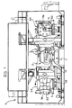
- a welding station of the type described in the document identified above is generally indicated 1.
- the bodies B to be welded are supplied to the welding station in succession by means of a conveyor line 2. Neither the structural details of the conveyor line 2 nor those of all the other known components of the welding station 1 are described in detail below since - as already indicated - these details are supplied in the document identified above. Moreover, these structural details do not fall within the scope of the present invention.
- the bodies B are supplied to the welding station in a provisionally-assembled condition which is achieved by the loose connection of the component parts of the body. This loose connection can be achieved by means of bent tongues forming parts of the component parts of the body.
- the pallet 2a which moves along the line 2 and supports a respective body B may be provided with means for supporting the various component parts of the body in positions approximating to their final welding positions.
- a drum 3 is provided on each side of the welding station and is mounted for rotation about an axis 3a parallel to the length of the conveyor line 2.
- Each drum 3 carries on its faces four locating frames G1, G2, G3 and G4, each of which supports a plurality of locating devices suitable for a specific type of motor-vehicle body and intended to clamp the component parts of a body of the respective type in the correct position for welding.
- the details of the structures of the locating frames and the way in which they are carried by the respective rotatable drum are not described in detail in the present description since they are also known from the prior document identified above.
- the clamping devices open and the two locating frames move outwardly to enable the welded body to be discharged from the station. If the next body to reach the welding station is of a different type from that welded previously, the two locating frames return to their respective rotatable drums and the latter are rotated until the new pair of locating frames are presented in positions facing the body to be welded, after which the cycle described above is repeated.
- the welding means provided to the station 1 are constituted by a plurality of programmable, electrical spot welding robots and/or by a plurality of welding guns arranged on the locating frames.
- each locating device 4 includes two elements 4a, 4b which are movable between an open position (not shown) and a closed position in which they clamp together two or more pressed-sheet-metal parts forming parts of the body B to be welded.
- the element 4a is fixed to the locating frame G, as is the respective laser torch 5 which is adapted to focus the laser beam on the region to be welded, making it pass through a hole 7 in the element 4a.
- each locating frame G has a set of optical distributor devices 8 each having an optical input for optical connection to a respective laser source S on the fixed structure of the welding station and a plurality of outputs 9 connected by means of bundles of optical fibres 6 to the laser torches 5 carried by the locating frame G.
- the optical distributor devices 8 are not shown in detail in the present description since they may be of any known type.
- optical distributors of this type are made and sold by Lumonics JK Industrial Products, together with YAG (Yttrium, Aluminium, Garnet) laser emitters.
- YAG Yttrium, Aluminium, Garnet
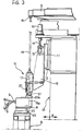
- the welding station has a plurality of quick-coupling devices 10 ( Figures 2, 3) which enable the optical connection of the inputs of the distributor devices 8 carried by a particular locating frame G to the laser sources S when the locating frame reaches the working position corresponding to the engagement of the locating devices 4 with the body to be welded.
- the quick-coupling device 10 comprises a slide 11 guided for vertical sliding on a guide 12 carried by the fixed structure 13 of the welding station 1 ( Figure 3).
- the slide 11 is moved vertically by a screw 14 which engages a nut 15 fixed to the slide 11.
- the screw 14 is rotated by an electric stepping motor 15 supported by the fixed structure 13.
- a bracket 16 is fixed to the slide 11 and supports a cylindrical body 17 which is guided for sliding on a vertical tubular shaft 18 whose upper end is connected to the output 19 of the laser source S.
- the lower end of the cylindrical body 17 comprises a tubular connecting element 20 with a flared conical mouth 20a which is adapted to be coupled to a conical appendage 21 of the distributor device 8, coaxial with the input of the distributor device 8.
- the slide 11 When the locating frame G is moving towards its working position in the welding station, the slide 11 is in the raised position. When the locating frame G has reached its working position, the conical appendage 21 is substantially aligned with the axis 18a of the tub- ularshaft 18. Once the frame G has stopped, the slide 11 is lowered so that the tubular element 20 fits onto the conical appendage 21. Any misalignment between the two coupling elements 20, 21 is corrected by virtue of the conical coupling since the distributor device 8 is supported by the locating frame G with the interposition of two perpendicular slides 22, 23.
- the device 8 is free to slide relative to the slide 23 along a line perpendicular to the plane of Figure 3, the slide in turn being slidable relative to the frame G in the directions indicated by the arrows A in Figure 3.
- the conical coupling forces the distributor 8 and the appendage 21 to assume the correct position.
- the laser beam emitted by the source S can reach the laser torches 5 carried by the frame G by passing through the tubular shaft 18, the cylindrical body 17, the optical distributor device 8 and the bundles of optical fibres 6.
- the slide 11 of each quick-coupling device 10 is raised to enable the locating frames G to be changed.
- the use of the quick-coupling device 10 also enables the application of welding by means of laser torches 5 to flexible welding stations of types different from that illustrated purely by way of example, in Figures 1-3, for example, of the type described in the same Applicant's German patent No. 2 810 822 and in the corresponding U.S. patent No. 4 162 387.
- FIG. 5 shows schematically, in plan, two welding stations 30A, 30B for operating on two different types of motor-vehicle body.
- Each welding station has a single pair of locating frames G provided with locating devices suitable for the configuration of the respective body type.
- a conveyor line 31 brings the bodies B1 and B2 of the two different types envisaged to the welding stations 30A, 30B in succession. Obviously, the bodies B1 stop only in the welding station 30A, whilst the bodies B2 stop only in the welding station 30B.
- Each locating frame G has a plurality of laser torches 5 associated with respective locating devices 4, in a manner similar to that illustrated in Figure 4.
- the laser torches 5 of the two pairs of frames G of the two stations 30A, 30B are connected by bundles of optical fibres 6 to a single laser emission system 35 which, in the embodiment illustrated, comprises a plurality of laser sources 36 each provided at its output with an optical distributor device 37 whose outputs are in turn connected by bundles of optical fibres 6 both to laser torches 5 of the station 30A and to laser torches 5 of the station 30B.
Abstract
Description
- The present invention relates to devices for welding motor-vehicle bodies. In particular, the invention concerns devices which provide for the welding of motor-vehicle bodies after they have been assembled provisionally by the loose connection of their component parts.
- Known devices of the type indicated above generally comprise a station for welding the bodies, a conveyor line for transporting the loosely preassembled bodies to the station, locating means provided at the station for clamping the component parts of the body in the correct position for welding, and welding means provided at the station for welding the component parts of the body together after they have been clamped by the locating means.
- During the last decade, the automotive industry has shown an ever greater tendency to use devices of the aforesaid type which have characteristics of flexibility, that is, which are adapted to operate on different body types. In fact, the use of flexible devices has drastically reduced the investment which was once necessary in order to bring a new model of car into production, as well as making the time needed to adapt the production plant to the new model of car practically negligible.
- As regards the welding means used in the devices of the type indicated above, the desired characteristics of flexibility have been achieved by the use of robots with electrical spot-welding heads, the robots being programmable in dependence on the specific type of body to be assembled.
- As far as the locating means for clamping the component parts of the bodies in the correct position for welding are concerned, however, the desired characteristics of flexibility have been achieved by the use of the invention which forms the subject of the same Applicant's German patent No. 2,810,822 and the corresponding U.S. patent No. 4,162,387.
- In the device described in the documents identified above, the welding station has at least two pairs of locating frames which can be interchanged rapidly in the working position, the frames of each pair carrying locating devices suitable forthe configuration of a respective type of body to be welded. Flexible welding devices of this type have been produced and sold by the Applicant to many of the major motor-vehicle manufacturers in Europe and the United States. Nevertheless, it is felt that there is a continuing need for further improvement of these known devices.
- From a different point of view, there is a need to make the welding means used in the devices as simple and cheap as possible. In fact, up to now, the use of flexible welding stations has generally been preferred to the use of several welding stations, each dedicated to a respective type of body to be welded, not only because the use of several stations takes up more space but also, and above all, because the cost of the welding robots makes it preferable to use a single set of robots which operate equally well on different body types, rather than respective sets of robots in several welding stations. Naturally, a simplification of the welding means could lead to the possible reconsideration of the use of "dedicated" welding stations and this would give greater choice to motor-vehicle manufacturers at the design stage, with the advantage that the best solution can be selected for the specific case under consideration at any time.
- The object of the present invention is to provide a satisfactory solution to all the problems indicated above.
- In order to achieve this object, the subject of the present invention is a device for welding motor-vehicle bodies which have been assembled loosely beforehand, comprising
- a station for welding the body,
- a conveyor line for transporting the loosely preassembled bodies to the station,
- locating means provided at the welding station for clamping the component parts of the body in the correct position for welding, and
- welding means provided at the station forweld- ing the component parts of the body together after they have been clamped by the locating means,
characterised in that the welding means comprise a plurality of laser-welding torches which are associated with the locating means and are connected to laser emission means by bundles of optical fibres. - In the present description and in the claims which follow, the term "laser-welding torch" is used to indicate an optical head forfocussing the laser beam sent to the head onto one or more welding points.
- In a preferred embodiment of the invention, the locating means comprise a plurality of locating devices supported by locating frames which also support the laser-welding torches, each locating frame also carrying at least one optical distributor device having an input for connection to a laser source and a plurality of outputs connected to the laser torches carried by the locating frame.
- To advantage, the invention described above can be used in flexible welding stations which are intended to operate on at least two different types of motor-vehicle body and have at least two pairs of locating frames suitable for respective body types, the two pairs of frames being rapidly interchangeable in the working position in dependence on the type of body to be welded in the welding station.
- In this case, a quick-coupling member is provided forthe optical connection between the optical input of a particular locating frame and the respective laser source when the locating frame reaches the working position.
- A different application of the invention described above provides for the use of a plurality of dedicated welding stations, that is, stations which are intended to operate on respective type of motor-vehicle body, each welding station having a pair of locating frames suitable for the respective body type and the laser emission means being connected to the welding torches of all the stations by bundles of optical fibres. In this application, the use of several dedicated stations does not involve an excessive increase in cost by virtue of the simplicity with which the welding means intended to operate in the various stations are produced.
- Further characteristics and advantages of the invention will become clear from the description which follows, with reference to the appended drawings, provided purely by way of non-limiting example, in which:
- Figure 1 is a schematic view of a welding device according to the invention,
- Figure 2 is a side view of the device of Figure 1,
- Figure 3 is a view of a detail of a device of Figure 1 on an enlarged scale,
- Figure 4 is a sectional view of a further detail of the device according to the invention on an enlarged scale, and
- Figure 5 shows a further embodiment of the invention.
- Figures 1-3 show, by way of example, the application of the invention to a flexible welding device of the type which forms the subject of European patent application No. EP-A-0 351 377 and the corresponding German utility model DE-U-8 812 396.
- With reference to Figures 1-3, a welding station of the type described in the document identified above is generally indicated 1. The bodies B to be welded are supplied to the welding station in succession by means of a conveyor line 2. Neither the structural details of the conveyor line 2 nor those of all the other known components of the welding station 1 are described in detail below since - as already indicated - these details are supplied in the document identified above. Moreover, these structural details do not fall within the scope of the present invention. The bodies B are supplied to the welding station in a provisionally-assembled condition which is achieved by the loose connection of the component parts of the body. This loose connection can be achieved by means of bent tongues forming parts of the component parts of the body. Alternatively, the
pallet 2a which moves along the line 2 and supports a respective body B may be provided with means for supporting the various component parts of the body in positions approximating to their final welding positions. - Still in a manner known from the German utility model DE-U-8 812 396, a
drum 3 is provided on each side of the welding station and is mounted for rotation about anaxis 3a parallel to the length of the conveyor line 2. Eachdrum 3 carries on its faces four locating frames G1, G2, G3 and G4, each of which supports a plurality of locating devices suitable for a specific type of motor-vehicle body and intended to clamp the component parts of a body of the respective type in the correct position for welding. The details of the structures of the locating frames and the way in which they are carried by the respective rotatable drum are not described in detail in the present description since they are also known from the prior document identified above. The same is true of the means for rotating therotatable drums 3 about theaxes 3a in order to present a respective pair of locating frames in positions facing the body in the welding station. As described in DE-U-8 812 396, each time a body B of a certain type reaches the welding station, thedrums 3 must be in a position such that the two frames G corresponding to the specific body type face the two sides of the body. At this point, transverse translation devices take the two frames G from the drums and move them towards the two sides of the body so that the locating devices (indicated 4 in Figures 1-3) can engage the body B and clamp its component parts in the correct position for welding. Once the welding has been carried out (by welding means which will be described below) the clamping devices open and the two locating frames move outwardly to enable the welded body to be discharged from the station. If the next body to reach the welding station is of a different type from that welded previously, the two locating frames return to their respective rotatable drums and the latter are rotated until the new pair of locating frames are presented in positions facing the body to be welded, after which the cycle described above is repeated. - In the prior document cited above, the welding means provided to the station 1 are constituted by a plurality of programmable, electrical spot welding robots and/or by a plurality of welding guns arranged on the locating frames.
- In the welding station according to the invention, however, the welding means are constituted by a plurality of laser-
welding torches 5 which are associated with an equivalent number of locating devices 4 carried by each locating frame G (Figure 4), and each of which receives a laser beam through a bundle ofoptical fibres 6. As illustrated in detail in Figure 4, each locating device 4 includes twoelements element 4a is fixed to the locating frame G, as is therespective laser torch 5 which is adapted to focus the laser beam on the region to be welded, making it pass through ahole 7 in theelement 4a. - In the preferred embodiment shown in Figures 1-3, each locating frame G has a set of
optical distributor devices 8 each having an optical input for optical connection to a respective laser source S on the fixed structure of the welding station and a plurality ofoutputs 9 connected by means of bundles ofoptical fibres 6 to thelaser torches 5 carried by the locating frame G. Theoptical distributor devices 8 are not shown in detail in the present description since they may be of any known type. For example, optical distributors of this type are made and sold by Lumonics JK Industrial Products, together with YAG (Yttrium, Aluminium, Garnet) laser emitters. In any case, the structures of the laser emittors and the respective optical distributors do not fall within the scope of the present invention. - According to the invention, the welding station has a plurality of quick-coupling devices 10 (Figures 2, 3) which enable the optical connection of the inputs of the
distributor devices 8 carried by a particular locating frame G to the laser sources S when the locating frame reaches the working position corresponding to the engagement of the locating devices 4 with the body to be welded. - The quick-
coupling device 10 comprises aslide 11 guided for vertical sliding on aguide 12 carried by thefixed structure 13 of the welding station 1 (Figure 3). Theslide 11 is moved vertically by a screw 14 which engages anut 15 fixed to theslide 11. The screw 14 is rotated by anelectric stepping motor 15 supported by thefixed structure 13. Abracket 16 is fixed to theslide 11 and supports acylindrical body 17 which is guided for sliding on a verticaltubular shaft 18 whose upper end is connected to theoutput 19 of the laser source S. - The lower end of the
cylindrical body 17 comprises a tubular connectingelement 20 with a flaredconical mouth 20a which is adapted to be coupled to aconical appendage 21 of thedistributor device 8, coaxial with the input of thedistributor device 8. - When the locating frame G is moving towards its working position in the welding station, the
slide 11 is in the raised position. When the locating frame G has reached its working position, theconical appendage 21 is substantially aligned with theaxis 18a of the tub-ularshaft 18. Once the frame G has stopped, theslide 11 is lowered so that thetubular element 20 fits onto theconical appendage 21. Any misalignment between the twocoupling elements distributor device 8 is supported by the locating frame G with the interposition of twoperpendicular slides device 8 is free to slide relative to theslide 23 along a line perpendicular to the plane of Figure 3, the slide in turn being slidable relative to the frame G in the directions indicated by the arrows A in Figure 3. The conical coupling forces thedistributor 8 and theappendage 21 to assume the correct position. Once the coupling device is in the operative position, the laser beam emitted by the source S can reach the laser torches 5 carried by the frame G by passing through thetubular shaft 18, thecylindrical body 17, theoptical distributor device 8 and the bundles ofoptical fibres 6. When the welding is completed, if the next body to be welded is of a different type, theslide 11 of each quick-coupling device 10 is raised to enable the locating frames G to be changed. - Naturally, the use of the quick-
coupling device 10 also enables the application of welding by means oflaser torches 5 to flexible welding stations of types different from that illustrated purely by way of example, in Figures 1-3, for example, of the type described in the same Applicant's German patent No. 2 810 822 and in the corresponding U.S. patent No. 4 162 387. - As indicated in the introduction to the present description, the invention also enables and makes economically advantageous a solution which provides for a plurality of welding stations dedicated to the various types of body to be welded. Figure 5 shows schematically, in plan, two
welding stations conveyor line 31 brings the bodies B1 and B2 of the two different types envisaged to thewelding stations welding station 30A, whilst the bodies B2 stop only in thewelding station 30B. Each locating frame G has a plurality oflaser torches 5 associated with respective locating devices 4, in a manner similar to that illustrated in Figure 4. The laser torches 5 of the two pairs of frames G of the twostations optical fibres 6 to a singlelaser emission system 35 which, in the embodiment illustrated, comprises a plurality oflaser sources 36 each provided at its output with anoptical distributor device 37 whose outputs are in turn connected by bundles ofoptical fibres 6 both tolaser torches 5 of thestation 30A and tolaser torches 5 of thestation 30B. - Naturally, the principle of the invention remaining the same, the details of construction and forms of embodiment may be varied widely with respect to those described and illustrated purely by way of example, without thereby departing from the scope of the present invention.
Claims (9)
characterised in that the welding means comprise a plurality of laserwelding torches (5) which are associated with the locating means (4) and are connected to laser emission means (S) by bundles of optical fibres (6).
Priority Applications (1)
| Application Number | Priority Date | Filing Date | Title |
|---|---|---|---|
| AT90830575T ATE100770T1 (en) | 1990-01-31 | 1990-12-11 | DEVICE FOR LASER WELDING OF CAR BODY. |
Applications Claiming Priority (2)
| Application Number | Priority Date | Filing Date | Title |
|---|---|---|---|
| IT67074A IT1239874B (en) | 1990-01-31 | 1990-01-31 | DEVICE FOR LASER WELDING OF VEHICLE BODIES |
| IT6707490 | 1990-01-31 |
Publications (3)
| Publication Number | Publication Date |
|---|---|
| EP0440001A1 EP0440001A1 (en) | 1991-08-07 |
| EP0440001B1 true EP0440001B1 (en) | 1994-01-26 |
| EP0440001B2 EP0440001B2 (en) | 1999-08-18 |
Family
ID=11299369
Family Applications (1)
| Application Number | Title | Priority Date | Filing Date |
|---|---|---|---|
| EP90830575A Expired - Lifetime EP0440001B2 (en) | 1990-01-31 | 1990-12-11 | A device for laser welding motor vehicle bodies |
Country Status (10)
| Country | Link |
|---|---|
| US (1) | US5064991A (en) |
| EP (1) | EP0440001B2 (en) |
| JP (1) | JP2657247B2 (en) |
| AT (1) | ATE100770T1 (en) |
| CA (1) | CA2033817C (en) |
| DE (1) | DE69006343T3 (en) |
| ES (1) | ES2048482T5 (en) |
| IT (1) | IT1239874B (en) |
| RU (1) | RU2012473C1 (en) |
| UA (1) | UA26367A (en) |
Cited By (1)
| Publication number | Priority date | Publication date | Assignee | Title |
|---|---|---|---|---|
| US7560659B2 (en) | 2004-05-28 | 2009-07-14 | Comau, S.P.A. | Robot-aided remote laser welding with simplified control of focusing direction of laser beam |
Families Citing this family (30)
| Publication number | Priority date | Publication date | Assignee | Title |
|---|---|---|---|---|
| EP0483652A1 (en) * | 1990-10-31 | 1992-05-06 | Yamazaki Mazak Kabushiki Kaisha | Laser machining cell |
| US5380978A (en) * | 1991-07-12 | 1995-01-10 | Pryor; Timothy R. | Method and apparatus for assembly of car bodies and other 3-dimensional objects |
| IT1249980B (en) * | 1991-08-07 | 1995-03-30 | Comau Spa | DEVICE FOR THE WELDING OF STRUCTURES, SUCH AS BODIES OF MOTOR VEHICLES OR PARTS OF THEM, MADE UP OF ELEMENTS OF PRINTED SHEET METAL ASSEMBLED PRELIMINARILY AMONG THEM IN A LABULAR WAY. |
| US5591358A (en) * | 1994-03-23 | 1997-01-07 | Progressive Tool & Industries Co. | Apparatus for clamping and laser welding |
| US5616261A (en) * | 1995-06-07 | 1997-04-01 | Chrysler Corporation | Laser welding system |
| US5674420A (en) * | 1995-06-12 | 1997-10-07 | Worthington Industries Incorporated | Clamping device for welding machine |
| US6153853A (en) * | 1996-12-25 | 2000-11-28 | Honda Giken Kogyo Kabushiki Kaisha | Laser beam welding apparatus |
| WO2000041848A1 (en) | 1999-01-11 | 2000-07-20 | Amada Company, Limited | Sheet working system |
| US6204469B1 (en) * | 1999-03-04 | 2001-03-20 | Honda Giken Kogyo Kabushiki Kaisha | Laser welding system |
| JP3302672B2 (en) * | 2000-03-23 | 2002-07-15 | ファナック株式会社 | Laser processing equipment |
| GB0008302D0 (en) * | 2000-04-06 | 2000-05-24 | British Aerospace | Assembly method |
| JP3421633B2 (en) * | 2000-04-11 | 2003-06-30 | ファナック株式会社 | Laser processing equipment |
| US6531675B2 (en) | 2001-01-31 | 2003-03-11 | Unova Ip Corp. | Laser welding method and apparatus |
| DE10133956B8 (en) * | 2001-07-17 | 2011-01-20 | Volkswagen Ag | Clamping device for laser soldering or laser welding |
| DE10151257B4 (en) * | 2001-10-17 | 2005-12-22 | Kuka Schweissanlagen Gmbh | Method for connecting body parts and framing station |
| US6825438B1 (en) * | 2003-05-29 | 2004-11-30 | Dana Corporation | Multi-head lasers cutting/welding cell with vibration control |
| DE50312360D1 (en) * | 2003-08-09 | 2010-03-11 | Trumpf Werkzeugmaschinen Gmbh | Laser processing nozzle coupling |
| CA2489941C (en) | 2003-12-18 | 2012-08-14 | Comau S.P.A. | A method and device for laser welding |
| FR2868718B1 (en) * | 2004-04-08 | 2007-06-29 | 3D Ind Soc Par Actions Simplif | LASER CUTTING DEVICE FOR TWISTING, ADJUSTING, PUNCHING |
| AT501245B1 (en) * | 2004-12-29 | 2006-11-15 | Sticht Fertigungstech Stiwa | Metalworking production line sub-assemblies move through a series of beam welding heads operated sequentially by the same power supply unit |
| ITTO20050053A1 (en) | 2005-01-31 | 2006-08-01 | Comau Spa | IMPROVEMENT TO THE ASSEMBLY SYSTEMS BY WELDING METAL SHEET STRUCTURES, IN PARTICULAR BODIES OF MOTOR VEHICLES OR THEIR SUBGROUPS |
| DE102005050249A1 (en) * | 2005-10-20 | 2007-04-26 | Volkswagen Ag | Bonding vehicle bodywork components, with a joint between them, has a flexible segment at one or both to move into the final nominal position during or after bonding forming a joint at zones difficult to access |
| DE102006021755A1 (en) * | 2006-05-10 | 2007-11-15 | Edag Engineering + Design Ag | Energy beam soldering or welding of components |
| DE102008052489B4 (en) * | 2008-10-21 | 2012-04-05 | Ibs Filtran Kunststoff-/ Metallerzeugnisse Gmbh | Device for welding two welding articles and method for operating the device |
| DE102009034066A1 (en) * | 2009-07-22 | 2011-01-27 | Volkswagen Ag | Device for manufacturing of motor vehicle body side parts on production line, has drum divided in longitudinal direction and exhibiting two drum sections with common rotation axis, where drum sections are rotatable relative to each other |
| JP5384284B2 (en) * | 2009-10-09 | 2014-01-08 | 株式会社ディスコ | Laser processing equipment |
| EP2821176A1 (en) * | 2013-07-02 | 2015-01-07 | Siemens VAI Metals Technologies GmbH | Device for moving an arrangement for cutting and welding metal strips ; Methof of cutting and welding using such device |
| JP2020151758A (en) * | 2019-03-20 | 2020-09-24 | 株式会社フジクラ | Laser processing device, laser processing method and method for manufacturing secondary battery |
| FR3112708A1 (en) | 2020-07-23 | 2022-01-28 | Psa Automobiles Sa | Service table for a laser device of a laser welding and/or laser brazing installation |
| DE102021127645A1 (en) * | 2021-10-25 | 2023-04-27 | André LeGuin | System for processing workpieces with a laser head |
Family Cites Families (2)
| Publication number | Priority date | Publication date | Assignee | Title |
|---|---|---|---|---|
| GB2191977B (en) * | 1986-06-24 | 1990-01-10 | Lamb Sceptre Ltd | Improvements in automobile body building methods and apparatus |
| JPH0829726B2 (en) * | 1988-07-18 | 1996-03-27 | 日産自動車株式会社 | Assembly method of car body |
-
1990
- 1990-01-31 IT IT67074A patent/IT1239874B/en active IP Right Grant
- 1990-12-11 ES ES90830575T patent/ES2048482T5/en not_active Expired - Lifetime
- 1990-12-11 EP EP90830575A patent/EP0440001B2/en not_active Expired - Lifetime
- 1990-12-11 AT AT90830575T patent/ATE100770T1/en not_active IP Right Cessation
- 1990-12-11 DE DE69006343T patent/DE69006343T3/en not_active Expired - Fee Related
-
1991
- 1991-01-08 US US07/638,673 patent/US5064991A/en not_active Expired - Lifetime
- 1991-01-09 CA CA002033817A patent/CA2033817C/en not_active Expired - Fee Related
- 1991-01-29 RU SU4894225/08A patent/RU2012473C1/en not_active IP Right Cessation
- 1991-01-29 UA UA4894225A patent/UA26367A/en unknown
- 1991-01-30 JP JP3098352A patent/JP2657247B2/en not_active Expired - Lifetime
Cited By (1)
| Publication number | Priority date | Publication date | Assignee | Title |
|---|---|---|---|---|
| US7560659B2 (en) | 2004-05-28 | 2009-07-14 | Comau, S.P.A. | Robot-aided remote laser welding with simplified control of focusing direction of laser beam |
Also Published As
| Publication number | Publication date |
|---|---|
| DE69006343T2 (en) | 1994-05-11 |
| DE69006343D1 (en) | 1994-03-10 |
| CA2033817A1 (en) | 1991-08-01 |
| UA26367A (en) | 1999-08-30 |
| EP0440001B2 (en) | 1999-08-18 |
| EP0440001A1 (en) | 1991-08-07 |
| CA2033817C (en) | 1994-09-13 |
| IT1239874B (en) | 1993-11-15 |
| US5064991A (en) | 1991-11-12 |
| ATE100770T1 (en) | 1994-02-15 |
| ES2048482T5 (en) | 1999-10-16 |
| ES2048482T3 (en) | 1994-03-16 |
| IT9067074A0 (en) | 1990-01-31 |
| DE69006343T3 (en) | 2000-03-30 |
| IT9067074A1 (en) | 1991-08-01 |
| JPH04238689A (en) | 1992-08-26 |
| RU2012473C1 (en) | 1994-05-15 |
| JP2657247B2 (en) | 1997-09-24 |
Similar Documents
| Publication | Publication Date | Title |
|---|---|---|
| EP0440001B1 (en) | A device for laser welding motor vehicle bodies | |
| EP0440002B2 (en) | Apparatus for welding motor-vehicle bodies | |
| EP0642878B1 (en) | Device for spot welding of structures formed of pressed sheet metal elements | |
| US5616261A (en) | Laser welding system | |
| US5902496A (en) | Device for spot welding of structures constituted by metal elements, particularly motor-vehicle bodies or sub-assemblies thereof | |
| EP1430989A1 (en) | Method and apparatus for positioning parts to be assembled | |
| CN109465588A (en) | A kind of self-centering inner support clamp of rectangular pipe fitting | |
| DE4004544A1 (en) | Distortion-free laser welding esp. for optical components - uses three laser focussing systems to weld rotationally symmetrical workpiece to second workpiece | |
| US4959521A (en) | Method and apparatus for fastening parts securely in place using a band | |
| CN207952916U (en) | Soldering turret repairs a die compensation device and soldering turret device | |
| US5845863A (en) | Winding apparatus for simultaneous winding of two CRT yokes | |
| US5690026A (en) | Arrangement for transferring workpieces through a succession of machining stations | |
| EP0529419A2 (en) | Capillary tube conduction system as well as the manufacture and device for manufacturing a capillary tube conduction system | |
| GB2151991A (en) | Vehicle assembly production line | |
| EP1355178B1 (en) | Method and device for welding contacts to optical waveguides | |
| CN213318481U (en) | Welding machine tool | |
| GB2234462A (en) | Method of and apparatus for welding panel with space defined therein | |
| EP0368389A1 (en) | System for welding structures composed of sheet metal, with prepositioned tools | |
| CN115722843A (en) | MOX subassembly equipment welding integrated device | |
| DE69719215T2 (en) | PLANT FOR ADJUSTING AND WELDING TWO WORKPIECES BY MEANS OF A HIGH-DENSITY ENERGY RAY | |
| CH684911A5 (en) | Armature winding machine. | |
| CS265335B1 (en) | Welding machine for welding on parts to an internal surface of hollow vessel | |
| KR19990084593A (en) | 2D Tailored Blank Welding System |
Legal Events
| Date | Code | Title | Description |
|---|---|---|---|
| PUAI | Public reference made under article 153(3) epc to a published international application that has entered the european phase |
Free format text: ORIGINAL CODE: 0009012 |
|
| AK | Designated contracting states |
Kind code of ref document: A1 Designated state(s): AT BE CH DE ES FR GB LI LU NL SE |
|
| 17P | Request for examination filed |
Effective date: 19911001 |
|
| 17Q | First examination report despatched |
Effective date: 19930312 |
|
| GRAA | (expected) grant |
Free format text: ORIGINAL CODE: 0009210 |
|
| AK | Designated contracting states |
Kind code of ref document: B1 Designated state(s): AT BE CH DE ES FR GB LI LU NL SE |
|
| REF | Corresponds to: |
Ref document number: 100770 Country of ref document: AT Date of ref document: 19940215 Kind code of ref document: T |
|
| REF | Corresponds to: |
Ref document number: 69006343 Country of ref document: DE Date of ref document: 19940310 |
|
| REG | Reference to a national code |
Ref country code: ES Ref legal event code: FG2A Ref document number: 2048482 Country of ref document: ES Kind code of ref document: T3 |
|
| ET | Fr: translation filed | ||
| PLBI | Opposition filed |
Free format text: ORIGINAL CODE: 0009260 |
|
| 26 | Opposition filed |
Opponent name: KUKA SCHWEISSANLAGEN + ROBOTER GMBH Effective date: 19941022 Opponent name: BAYERISCHE MOTOREN WERKE AKTIENGESELLSCHAFT Effective date: 19941021 |
|
| EAL | Se: european patent in force in sweden |
Ref document number: 90830575.8 |
|
| NLR1 | Nl: opposition has been filed with the epo |
Opponent name: ROBOTER GMBH Opponent name: KUKA SCHWEISSANLAGEN Opponent name: BAYERISCHE MOTOREN WERKE AKTIENGESELLSCHAFT |
|
| PLAW | Interlocutory decision in opposition |
Free format text: ORIGINAL CODE: EPIDOS IDOP |
|
| REG | Reference to a national code |
Ref country code: CH Ref legal event code: NV Representative=s name: ISLER & PEDRAZZINI AG |
|
| APAC | Appeal dossier modified |
Free format text: ORIGINAL CODE: EPIDOS NOAPO |
|
| APAE | Appeal reference modified |
Free format text: ORIGINAL CODE: EPIDOS REFNO |
|
| APAC | Appeal dossier modified |
Free format text: ORIGINAL CODE: EPIDOS NOAPO |
|
| APAC | Appeal dossier modified |
Free format text: ORIGINAL CODE: EPIDOS NOAPO |
|
| PLAW | Interlocutory decision in opposition |
Free format text: ORIGINAL CODE: EPIDOS IDOP |
|
| PUAH | Patent maintained in amended form |
Free format text: ORIGINAL CODE: 0009272 |
|
| STAA | Information on the status of an ep patent application or granted ep patent |
Free format text: STATUS: PATENT MAINTAINED AS AMENDED |
|
| 27A | Patent maintained in amended form |
Effective date: 19990818 |
|
| AK | Designated contracting states |
Kind code of ref document: B2 Designated state(s): AT BE CH DE ES FR GB LI LU NL SE |
|
| REG | Reference to a national code |
Ref country code: CH Ref legal event code: AEN Free format text: MAINTIEN DU BREVET DONT L'ETENDUE A ETE MODIFIEE |
|
| REG | Reference to a national code |
Ref country code: ES Ref legal event code: DC2A Kind code of ref document: T5 Effective date: 19990902 |
|
| ET3 | Fr: translation filed ** decision concerning opposition | ||
| NLR3 | Nl: receipt of modified translations in the netherlands language after an opposition procedure | ||
| REG | Reference to a national code |
Ref country code: GB Ref legal event code: IF02 |
|
| PGFP | Annual fee paid to national office [announced via postgrant information from national office to epo] |
Ref country code: ES Payment date: 20031114 Year of fee payment: 14 |
|
| PGFP | Annual fee paid to national office [announced via postgrant information from national office to epo] |
Ref country code: LU Payment date: 20031126 Year of fee payment: 14 |
|
| PGFP | Annual fee paid to national office [announced via postgrant information from national office to epo] |
Ref country code: SE Payment date: 20031128 Year of fee payment: 14 Ref country code: NL Payment date: 20031128 Year of fee payment: 14 |
|
| PGFP | Annual fee paid to national office [announced via postgrant information from national office to epo] |
Ref country code: GB Payment date: 20031210 Year of fee payment: 14 |
|
| PGFP | Annual fee paid to national office [announced via postgrant information from national office to epo] |
Ref country code: BE Payment date: 20031212 Year of fee payment: 14 |
|
| PGFP | Annual fee paid to national office [announced via postgrant information from national office to epo] |
Ref country code: CH Payment date: 20031216 Year of fee payment: 14 |
|
| PGFP | Annual fee paid to national office [announced via postgrant information from national office to epo] |
Ref country code: AT Payment date: 20031218 Year of fee payment: 14 |
|
| PGFP | Annual fee paid to national office [announced via postgrant information from national office to epo] |
Ref country code: FR Payment date: 20031226 Year of fee payment: 14 |
|
| PGFP | Annual fee paid to national office [announced via postgrant information from national office to epo] |
Ref country code: DE Payment date: 20040227 Year of fee payment: 14 |
|
| PG25 | Lapsed in a contracting state [announced via postgrant information from national office to epo] |
Ref country code: LU Free format text: LAPSE BECAUSE OF NON-PAYMENT OF DUE FEES Effective date: 20041211 Ref country code: GB Free format text: LAPSE BECAUSE OF NON-PAYMENT OF DUE FEES Effective date: 20041211 Ref country code: AT Free format text: LAPSE BECAUSE OF NON-PAYMENT OF DUE FEES Effective date: 20041211 |
|
| PG25 | Lapsed in a contracting state [announced via postgrant information from national office to epo] |
Ref country code: SE Free format text: LAPSE BECAUSE OF NON-PAYMENT OF DUE FEES Effective date: 20041212 |
|
| PG25 | Lapsed in a contracting state [announced via postgrant information from national office to epo] |
Ref country code: ES Free format text: LAPSE BECAUSE OF NON-PAYMENT OF DUE FEES Effective date: 20041213 |
|
| PG25 | Lapsed in a contracting state [announced via postgrant information from national office to epo] |
Ref country code: LI Free format text: LAPSE BECAUSE OF NON-PAYMENT OF DUE FEES Effective date: 20041231 Ref country code: CH Free format text: LAPSE BECAUSE OF NON-PAYMENT OF DUE FEES Effective date: 20041231 Ref country code: BE Free format text: LAPSE BECAUSE OF NON-PAYMENT OF DUE FEES Effective date: 20041231 |
|
| BERE | Be: lapsed |
Owner name: *COMAU S.P.A. Effective date: 20041231 |
|
| PG25 | Lapsed in a contracting state [announced via postgrant information from national office to epo] |
Ref country code: NL Free format text: LAPSE BECAUSE OF NON-PAYMENT OF DUE FEES Effective date: 20050701 Ref country code: DE Free format text: LAPSE BECAUSE OF NON-PAYMENT OF DUE FEES Effective date: 20050701 |
|
| EUG | Se: european patent has lapsed | ||
| GBPC | Gb: european patent ceased through non-payment of renewal fee |
Effective date: 20041211 |
|
| REG | Reference to a national code |
Ref country code: CH Ref legal event code: PL |
|
| PG25 | Lapsed in a contracting state [announced via postgrant information from national office to epo] |
Ref country code: FR Free format text: LAPSE BECAUSE OF NON-PAYMENT OF DUE FEES Effective date: 20050831 |
|
| NLV4 | Nl: lapsed or anulled due to non-payment of the annual fee |
Effective date: 20050701 |
|
| APAH | Appeal reference modified |
Free format text: ORIGINAL CODE: EPIDOSCREFNO |
|
| REG | Reference to a national code |
Ref country code: FR Ref legal event code: ST |
|
| REG | Reference to a national code |
Ref country code: ES Ref legal event code: FD2A Effective date: 20041213 |
|
| BERE | Be: lapsed |
Owner name: *COMAU S.P.A. Effective date: 20041231 |