EP0439109A2 - Nebulizer - Google Patents
Nebulizer Download PDFInfo
- Publication number
- EP0439109A2 EP0439109A2 EP91100734A EP91100734A EP0439109A2 EP 0439109 A2 EP0439109 A2 EP 0439109A2 EP 91100734 A EP91100734 A EP 91100734A EP 91100734 A EP91100734 A EP 91100734A EP 0439109 A2 EP0439109 A2 EP 0439109A2
- Authority
- EP
- European Patent Office
- Prior art keywords
- cap
- under
- bottle
- section
- nebulizer
- Prior art date
- Legal status (The legal status is an assumption and is not a legal conclusion. Google has not performed a legal analysis and makes no representation as to the accuracy of the status listed.)
- Withdrawn
Links
Images

Classifications
-
- B—PERFORMING OPERATIONS; TRANSPORTING
- B05—SPRAYING OR ATOMISING IN GENERAL; APPLYING FLUENT MATERIALS TO SURFACES, IN GENERAL
- B05B—SPRAYING APPARATUS; ATOMISING APPARATUS; NOZZLES
- B05B1/00—Nozzles, spray heads or other outlets, with or without auxiliary devices such as valves, heating means
- B05B1/34—Nozzles, spray heads or other outlets, with or without auxiliary devices such as valves, heating means designed to influence the nature of flow of the liquid or other fluent material, e.g. to produce swirl
- B05B1/3405—Nozzles, spray heads or other outlets, with or without auxiliary devices such as valves, heating means designed to influence the nature of flow of the liquid or other fluent material, e.g. to produce swirl to produce swirl
- B05B1/341—Nozzles, spray heads or other outlets, with or without auxiliary devices such as valves, heating means designed to influence the nature of flow of the liquid or other fluent material, e.g. to produce swirl to produce swirl before discharging the liquid or other fluent material, e.g. in a swirl chamber upstream the spray outlet
-
- B—PERFORMING OPERATIONS; TRANSPORTING
- B05—SPRAYING OR ATOMISING IN GENERAL; APPLYING FLUENT MATERIALS TO SURFACES, IN GENERAL
- B05B—SPRAYING APPARATUS; ATOMISING APPARATUS; NOZZLES
- B05B11/00—Single-unit hand-held apparatus in which flow of contents is produced by the muscular force of the operator at the moment of use
- B05B11/01—Single-unit hand-held apparatus in which flow of contents is produced by the muscular force of the operator at the moment of use characterised by the means producing the flow
- B05B11/04—Deformable containers producing the flow, e.g. squeeze bottles
- B05B11/042—Deformable containers producing the flow, e.g. squeeze bottles the spray being effected by a gas or vapour flow in the nozzle, spray head, outlet or dip tube
- B05B11/043—Deformable containers producing the flow, e.g. squeeze bottles the spray being effected by a gas or vapour flow in the nozzle, spray head, outlet or dip tube designed for spraying a liquid
-
- B—PERFORMING OPERATIONS; TRANSPORTING
- B05—SPRAYING OR ATOMISING IN GENERAL; APPLYING FLUENT MATERIALS TO SURFACES, IN GENERAL
- B05B—SPRAYING APPARATUS; ATOMISING APPARATUS; NOZZLES
- B05B11/00—Single-unit hand-held apparatus in which flow of contents is produced by the muscular force of the operator at the moment of use
- B05B11/01—Single-unit hand-held apparatus in which flow of contents is produced by the muscular force of the operator at the moment of use characterised by the means producing the flow
- B05B11/04—Deformable containers producing the flow, e.g. squeeze bottles
- B05B11/047—Deformable containers producing the flow, e.g. squeeze bottles characterised by the outlet or venting means
-
- B—PERFORMING OPERATIONS; TRANSPORTING
- B65—CONVEYING; PACKING; STORING; HANDLING THIN OR FILAMENTARY MATERIAL
- B65D—CONTAINERS FOR STORAGE OR TRANSPORT OF ARTICLES OR MATERIALS, e.g. BAGS, BARRELS, BOTTLES, BOXES, CANS, CARTONS, CRATES, DRUMS, JARS, TANKS, HOPPERS, FORWARDING CONTAINERS; ACCESSORIES, CLOSURES, OR FITTINGS THEREFOR; PACKAGING ELEMENTS; PACKAGES
- B65D47/00—Closures with filling and discharging, or with discharging, devices
- B65D47/04—Closures with discharging devices other than pumps
- B65D47/20—Closures with discharging devices other than pumps comprising hand-operated members for controlling discharge
- B65D47/24—Closures with discharging devices other than pumps comprising hand-operated members for controlling discharge with poppet valves or lift valves, i.e. valves opening or closing a passageway by a relative motion substantially perpendicular to the plane of the seat
- B65D47/241—Closures with discharging devices other than pumps comprising hand-operated members for controlling discharge with poppet valves or lift valves, i.e. valves opening or closing a passageway by a relative motion substantially perpendicular to the plane of the seat the valve being opened or closed by actuating a cap-like element
- B65D47/242—Closures with discharging devices other than pumps comprising hand-operated members for controlling discharge with poppet valves or lift valves, i.e. valves opening or closing a passageway by a relative motion substantially perpendicular to the plane of the seat the valve being opened or closed by actuating a cap-like element moving helically
Definitions
- the invention concerns the disclosure of a nubulizer particularly suited to be applied on bottles containing liquid substances for medical, cosmetical or hygienic/sanitary use.
- nebulizers are devices permitting the dispersion in the air or in any gaseous substance of a liquid in the form of very minute drops.
- Nebulizers are largely used particularly in the cosmetic and the hygienic/sanitary fields, where they are applied to containers holding liquids which are then nebulized and dispersed in the air or spread on people's bodies.
- nebulizers which are used in the above-mentioned fields of application, consist essentially of an under-cap, which is applied on the neck of the container and presents a tube-shaped duct with a tiny tube attached to it, which draws the liquid held in the container.
- the under-cap is complete with a pin with a spraying hole having a helicoidal-tapered cross-section and the nebulizer is usually protected by a cap which is usually inserted by pressure or by screwing on the container.
- the small tube is inserted in a swirl chamber belonging to the under-cap, into which the liquid held in the container is conveyed, after it has been pushed upwards through the tube.
- the liquid is pushed upwards by the mechanical deformation of the container, if the latter is deformable and elastic or, in other cases, by the pressure exerted by a compressed gas, for instance freon, held in the container itself, when the latter is rigid.
- a compressed gas for instance freon
- the liquid undergoes a first disintegrating process which will be further incremented when, after it has already been reduced to minute drops, it goes through the hole with a tapered helicoidal cross-section of the pin applied to the under-cap, before it is conveyed outside into the environment.
- nebulizers belong to the known technique, which are used not only in the above-mentioned fields of application, but also in the industrial fields, wherein the liquid held in the container is sucked by means of compressed air through a small tube drawing from the container and is sent into the outside environment in a nebulized form by exploiting the known Venturi principle.
- nebulizers The main inconvenience presented by the known types of nebulizers consists in that the degree of nebulization of the liquid they achieve is often rather coarse, since it consists of a plurality of tiny drops dispersed in the air, rather than of a mist.
- Another inconvenience consists in that before spraying it is necessary to remove the protective cap, which may be lost, thereby causing uneasiness to the user.
- the present invention proposes to eliminate the described inconveniences and has the main purpose of disclosing a nebulizer which yields a higher degree of nebulization of the sprayed liquid in comparison with the nebulization obtained with the nebulizers belonging to the known technique.
- Another purpose is to disclose a nebulizer obtaining a very fine nebulization preventing the collection of drops on the spraying hole and, therefore, the formation of drippings during the spraying process.
- Another purpose is to disclose a nebulizer wherein the cap is constantly attached to the bottle or to the container holding the liquid to be sprayed.
- nebulizer which can be completely pre-assembled in all of its parts, regardless of the container which will receive it, so that the only task of the bottling company will be to connect the nebulizer with the neck of the bottle with a single screwing operation.
- nebulizer which can be applied on a bottle and which, in accordance with the claims, comprises:
- the nebulizer according to the invention has two swirl chambers rather than a single one, and more precisely, a primary chamber which is comprised between the edge of the small tube and the interior of the holow cylindrical section of the under-cap, and a secondary chamber which is coaxial with the former and is comprised between the outer part of the cylindrical section of the under-cap and the innerly hollow cylindrical section of the cap, so that it permits a very fine nebulization of the liquid contained in the bottle, the degree of said nebulization being much finer than the degree of nebulization obtained with the nebulizers of the known type.
- the small tube, the under-cap and the cap can be assembled together, so that the nebulizer thus assembled can be applied by the customer around the neck of the bottle by simply screwing it on the outer thread of the bottle neck.
- the annular peripheral part of the under-cap penetrates under pressure into the opening of the bottle neck and insures the stable junction of the nebulizer to the bottle.
- the nebulizer according to the invention which is indicated as a whole with 1, is applied on a bottle 2, which is of the elastic and deformable type and contains the liquid to be nebulized.
- nebulizer is represented in its longitudinal cross-section in Fig. 2, where it is possible to observe the parts composing it, which consist of an under-cap 3, presenting an annular peripheral section 4 which is inserted into the bottle neck 5, which it seals, and a central cylindrical section 6, which is co-axial with the peripheral annular section 4, which is innerly hollow.
- the small tube 7 which is immersed in the liquid 8 contained within the bottle. Its end 30, which is opposed to the immersed end, is flush against the spacing teeth 9 of the under-cap 4, which are visible in a clearer detail in Fig. 5. Said teeth match the holes 10, which are more clearly visible in Fig.
- the external area of the under-cap 3, with which the holes 10 connect the inside of the bottle, is, as can be obeserved in Fig. 2 and even better in Fig. 3, another chamber 13, comprised within the inner hollow part of a cylindrical section 14, belonging to the cap 15 of the nebulizer. Said cap is applied around the bottle neck 5 by tightening it on thread 16. Said chamber 13 acquires various volumes, as can be seen in the Figs. 2 and 3, which are comprised between the minimum value represented in Fig. 2, when the cap 15 is completely tightened, up to the maximum value represented in Fig. 3, when the same cap 15 is untightened to the end of its stroke. It can also be observed that, when the chamber acquires its minimum volume, i.e. when cap 15 is completely tightened around the bottle neck, a stopper 17 having a conical profile at its top end and being arranged centrally in the central cylindrical section 6 of the under-cap 3, seals hermetically the spraying hole 18 bored in cap 15.
- cap 15 In order to spray the liquid 8 contained within bottle 2, one must, first of all, untighten cap 15 and bring it to the position represented in Fig. 3, so that the stopper 17 of the under-cap 3 no longer shuts the spraying hole 18. It will be pointed out that in the position of maximum opening represented in Fig. 3 cap 15 still remains attached to the bottle neck 5, since an annular rim 40 belonging to the latter contrasts against an annular rim 41 belonging to cap 15, which prevent the separation of one from the other. At this point, by pressing the body of the bottle 2, a pumping action is conveyed to the liquid 8, contained therein, which ascends vertically through channel 19 of the small tube 7, following the direction indicated by the arrows 20.
- the primary swirl chamber When the liquid reaches chamber 12, which will be called the primary swirl chamber, it undergoes a first, coarse nebulization process, since it violently dashes against the spacing teeth 9; the partially nebulized liquid is conveyed through the holes 10 which carry it to the next chamber 13, which will be called the secondary swirl chamber.
- the secondary swirl chamber the liquid, which has already been nebulized in the primary swirl chamber 12, undergoes another nebulizing process by dashing against the walls of the chamber and against the body of the stopper 17, which is positioned at the center of the chamber itself.
- the nebulized liquid dashes against the inner edge 22 of the spraying hole 18, where it undergoes yet another nebulization process, before it is sent out into the outside environment 24 with a jet 21, which acquires its tapered shape from the shape of the spraying hole 18, which diverges outwardly in its section 25 connecting it to the outside environment 24.
- the inner rim 22 of section 23 converging toward the exterior 24 of the spraying hole 18 consists of a circular depression 33, co-axial with the central circular section 27 of hole 18.
- said inner rim 22 can also be made by shaping the converging section 23 of the spraying hole 18 following other geometrical shapes or by shaping the entire converging surface 23 according to suitable geometrical shapes. After the spraying operation has been completed, cap 15 will be tightened completely around the bottle neck and the stopper 17 will hermetically seal the spraying hole 18.
- said fine nebulization 21 prevents the collection around the spraying hole 18 of several drops, and, as a consequence, it prevents drippings along the outer surface of cap 15.
- the shrinking of the peripheral annular section 4 of the under-cap 3 into the bottle neck 5 occurs at the same time as the tightening of cap 15.
- cap 15 it is necessary to force cap 15 to its end stroke, in order to force the annular projection 41 of cap 15 to go over the safety projection 40 belonging to the bottle neck 5.
- the small tube 7 presents a plurality of longitudinal splines 31, which fulfil the important task of permitting a faster re-entry of air within the volume 11 of the bottle, when the mechanical outside pressure, which has produced the spraying of liquid 8 to the exterior, is released.
- Fig. 9 represents a different embodiment of the nebulizer according to the invention, wherein the under-cap 60 presents some characteristics permitting it to be tightened directly around the neck of the bottle receiving it and it also presents a central stopper suited to the application of small tubes of the cylindrical type, rahter than of the type with the complex cross-section, which has been described in the preceding example of embodiment. More specifically, it will be observed in Fig. 9 that the under-cap 60 is so shaped as to present in its peripheral rim an indentation 61 acting as an undercut and contrasting against the protruding rim 71 of the bottle neck 70.
- stopper 75 it can be observed still in Fig. 9, that its lower part presents a triangular or, at any rate, polygonal shape, while the central cylindrical section 96 of the under-cap 60 presents some projections 97, as can be observed also in the detail represented in Fig. 10.
- the small tube 77 of the type with a cylindrical cross-section which can be normally found on the market, can easily be inserted by contrast between the lower part 76 of stopper 75 and the projections 97 of the central cylindrical section 96 of the under-cap 60.
- Said junction creates some channels 78 and 98 through which air flows going through hole 82, the holes 90 and the channels 78 and 98, after the nebulization action has stopped and the bottle recovers its original volume, after the deforming action, which has caused the spraying, has ceased.
- Fig. 9 offers the advantage of obtaining a nebulizer with an under-cap which is essentially immune from entrainment due to the friction caused by the cap, when the latter is screwed and unscrewed. Moreover, it is possible to use small tubes of the cylindrical type which are easily found on the market and inexpensive, for the construction of the nebulizer. These advantages are achieved simply by changing the shape of the terminal part of the stopper of the under-cap.
- the terminal section of the stopper has a triangular shape, but obviously any type of polygonal or star shape, or at any rate any shape not coinciding with the circle can permit the formation of the channels 78 and, thereby reach the proposed purpose.
Landscapes
- Engineering & Computer Science (AREA)
- Mechanical Engineering (AREA)
- Closures For Containers (AREA)
Abstract
The invention discloses a nebulizer comprising an under-cap (3) inserted into the neck (5) of a bottle (2), a small tube (7) drawing the liquid (8) contained in the bottle and coupled with the underside of the under-cap (3), where there is a primary swirl chamber (12), and a cap (15) placed over the under-cap (3) and screwed around the exterior of the bottle neck (5)> The cap (15) presents an inner hollow cylindrical section (14) which, together with the under-cap (3) creates a secondary swirl chamber (13), communicating at its bottom with the primary swirl chamber (12) and at its top with the spraying hole (18). The hermetic seal of the spraying hole (18) occurs by tightening the cap (15) to the end of the thread.
Description
- The invention concerns the disclosure of a nubulizer particularly suited to be applied on bottles containing liquid substances for medical, cosmetical or hygienic/sanitary use.
- It is a known fact that nebulizers are devices permitting the dispersion in the air or in any gaseous substance of a liquid in the form of very minute drops.
- Nebulizers are largely used particularly in the cosmetic and the hygienic/sanitary fields, where they are applied to containers holding liquids which are then nebulized and dispersed in the air or spread on people's bodies.
- The known types of nebulizers, which are used in the above-mentioned fields of application, consist essentially of an under-cap, which is applied on the neck of the container and presents a tube-shaped duct with a tiny tube attached to it, which draws the liquid held in the container. The under-cap is complete with a pin with a spraying hole having a helicoidal-tapered cross-section and the nebulizer is usually protected by a cap which is usually inserted by pressure or by screwing on the container. The small tube is inserted in a swirl chamber belonging to the under-cap, into which the liquid held in the container is conveyed, after it has been pushed upwards through the tube. In some cases the liquid is pushed upwards by the mechanical deformation of the container, if the latter is deformable and elastic or, in other cases, by the pressure exerted by a compressed gas, for instance freon, held in the container itself, when the latter is rigid. In the swirl chamber the liquid undergoes a first disintegrating process which will be further incremented when, after it has already been reduced to minute drops, it goes through the hole with a tapered helicoidal cross-section of the pin applied to the under-cap, before it is conveyed outside into the environment. Some other types of nebulizers belong to the known technique, which are used not only in the above-mentioned fields of application, but also in the industrial fields, wherein the liquid held in the container is sucked by means of compressed air through a small tube drawing from the container and is sent into the outside environment in a nebulized form by exploiting the known Venturi principle.
- The main inconvenience presented by the known types of nebulizers consists in that the degree of nebulization of the liquid they achieve is often rather coarse, since it consists of a plurality of tiny drops dispersed in the air, rather than of a mist.
- Another inconvenience is that in said types of nebulizers the outcoming drops often collect around the spraying hole, thereby causing liquid drippings and, therefore uneasthetical spillings of the liquid outside the container, especially in the case of protracted spraying.
- Another inconvenience consists in that before spraying it is necessary to remove the protective cap, which may be lost, thereby causing uneasiness to the user.
- Not the least inconvenience consists in that the nebulizers belonging to the known technique are sold to the buyer in separate pieces and he must then assemble them. It is obvious that this may create disadvantages, such as loss of time for the assembly, besides the fact that during the assembly some of the components may be lost.
- The present invention proposes to eliminate the described inconveniences and has the main purpose of disclosing a nebulizer which yields a higher degree of nebulization of the sprayed liquid in comparison with the nebulization obtained with the nebulizers belonging to the known technique.
- Another purpose is to disclose a nebulizer obtaining a very fine nebulization preventing the collection of drops on the spraying hole and, therefore, the formation of drippings during the spraying process.
- Another purpose is to disclose a nebulizer wherein the cap is constantly attached to the bottle or to the container holding the liquid to be sprayed.
- Not the least purpose is to disclose a nebulizer which can be completely pre-assembled in all of its parts, regardless of the container which will receive it, so that the only task of the bottling company will be to connect the nebulizer with the neck of the bottle with a single screwing operation.
- All the just mentioned purposes and others which will be better understood hereafter are reached through a nebulizer which can be applied on a bottle and which, in accordance with the claims, comprises:
- an under-cap consisting of an element made of plastic material and presenting a peripheral annular section, complete with an annular rim and co-operating with the neck of the bottle, which it seals, and a cylindrical section, which is hollow, co-axial with the annular peripheral section and presenting, in the upper part of its interior, some spacing teeth matching a corresponding number of through-going openings obtained in the thickness of its said upper part;
- a small tube drawing the liquid contained in the bottle and having its end, which is opposed to the drawing end, co-axially attached inside the cylindrical section of the under-cap and with its upper edge flush against the spacing teeth;
- a primary swirl chamber comprised between the end of the small tube, which is flush against the spacing teeth, and the upper wall where the teeth are attached;
- a centrally perforated cap, applied over the under-cap and screwed around the exterior of the bottle neck,
- Advantageously the nebulizer according to the invention has two swirl chambers rather than a single one, and more precisely, a primary chamber which is comprised between the edge of the small tube and the interior of the holow cylindrical section of the under-cap, and a secondary chamber which is coaxial with the former and is comprised between the outer part of the cylindrical section of the under-cap and the innerly hollow cylindrical section of the cap, so that it permits a very fine nebulization of the liquid contained in the bottle, the degree of said nebulization being much finer than the degree of nebulization obtained with the nebulizers of the known type.
- Advantageously, moreover, the small tube, the under-cap and the cap can be assembled together, so that the nebulizer thus assembled can be applied by the customer around the neck of the bottle by simply screwing it on the outer thread of the bottle neck. In fact, while this screwing operation is taking place, the annular peripheral part of the under-cap penetrates under pressure into the opening of the bottle neck and insures the stable junction of the nebulizer to the bottle.
- Further scope of applicability of the present invention will become apparent from the detailed description given hereinafter. However, it should be understood that the detailed description and the specific examples, while indicating preferred embodiments of the invention, are given by way of illustration only, since various changes and modifications within the spirit and scope of the invention will become apparent to those skilled in the art from this detailed description and from the drawings, wherein:
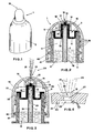
- Fig. 1 represents a bottle with the nebulizer according to the invention applied to it;
- Fig. 2 shows the longitudinal cross-section of the nebulizer of the invention with the sealing cap completely screwed on the bottle aand with its spraying hole closed;
- Fig. 3 shows the nebulizer of Fig. 2 during the spraying process, with the cap unscrewed and the spraying hole open;
- Fig. 4 shows in detail the spraying hole in its longitudinal cross-section;
- Fig. 5 shows the longitudinal cross-section of the under-cap of the nebulizer according to the invention;
- Fig. 6 represents a top view of the under-cap of Fig. 5;
- Fig. 7 represents the longitudinal view of the small tube drawing the liquid to be nebulized;
- Fig. 8 shows a plan view of the small tube of Fig. 7.
- Fig. 9 represents a longitudinal cross-view of another embodiment of the nebulizer according to the invention, with the sealing cap completely tightened and the spraying hole closed;
- Fig. 10 represents the transversal cross-section of the attachment of the small tube to the under-cap of the nebulizer in the embodiment represented in Fig. 9.
- As can be observed in Fig. 1, the nebulizer according to the invention, which is indicated as a whole with 1, is applied on a
bottle 2, which is of the elastic and deformable type and contains the liquid to be nebulized. - The same nebulizer according to the invention is represented in its longitudinal cross-section in Fig. 2, where it is possible to observe the parts composing it, which consist of an under-
cap 3, presenting an annularperipheral section 4 which is inserted into thebottle neck 5, which it seals, and a centralcylindrical section 6, which is co-axial with the peripheralannular section 4, which is innerly hollow. Inside thecylindrical section 6 of the under-cap is inserted thesmall tube 7 which is immersed in theliquid 8 contained within the bottle. Itsend 30, which is opposed to the immersed end, is flush against thespacing teeth 9 of the under-cap 4, which are visible in a clearer detail in Fig. 5. Said teeth match theholes 10, which are more clearly visible in Fig. 6 and connect the inside of under-cap 3 and, therefore, of the bottle itself, with the area outside the under-cap 3. Therefore, the presence of theteeth 9 determines the formation of achamber 12 comprised between theupper edge 30 of thesmall tube 7 and the upper underside area of thecylindrical section 6 of the under-cap 3. - The external area of the under-
cap 3, with which theholes 10 connect the inside of the bottle, is, as can be obeserved in Fig. 2 and even better in Fig. 3, anotherchamber 13, comprised within the inner hollow part of acylindrical section 14, belonging to thecap 15 of the nebulizer. Said cap is applied around thebottle neck 5 by tightening it onthread 16. Saidchamber 13 acquires various volumes, as can be seen in the Figs. 2 and 3, which are comprised between the minimum value represented in Fig. 2, when thecap 15 is completely tightened, up to the maximum value represented in Fig. 3, when thesame cap 15 is untightened to the end of its stroke. It can also be observed that, when the chamber acquires its minimum volume, i.e. whencap 15 is completely tightened around the bottle neck, astopper 17 having a conical profile at its top end and being arranged centrally in the centralcylindrical section 6 of the under-cap 3, seals hermetically thespraying hole 18 bored incap 15. - In order to spray the
liquid 8 contained withinbottle 2, one must, first of all, untightencap 15 and bring it to the position represented in Fig. 3, so that thestopper 17 of the under-cap 3 no longer shuts thespraying hole 18. It will be pointed out that in the position of maximum opening represented in Fig. 3cap 15 still remains attached to thebottle neck 5, since anannular rim 40 belonging to the latter contrasts against anannular rim 41 belonging tocap 15, which prevent the separation of one from the other. At this point, by pressing the body of thebottle 2, a pumping action is conveyed to theliquid 8, contained therein, which ascends vertically throughchannel 19 of thesmall tube 7, following the direction indicated by thearrows 20. When the liquid reacheschamber 12, which will be called the primary swirl chamber, it undergoes a first, coarse nebulization process, since it violently dashes against thespacing teeth 9; the partially nebulized liquid is conveyed through theholes 10 which carry it to thenext chamber 13, which will be called the secondary swirl chamber. In this secondary swirl chamber, the liquid, which has already been nebulized in theprimary swirl chamber 12, undergoes another nebulizing process by dashing against the walls of the chamber and against the body of thestopper 17, which is positioned at the center of the chamber itself. Moreover, as can be observed in Fig. 4, before going out through thespraying hole 18, the nebulized liquid dashes against theinner edge 22 of thespraying hole 18, where it undergoes yet another nebulization process, before it is sent out into theoutside environment 24 with ajet 21, which acquires its tapered shape from the shape of thespraying hole 18, which diverges outwardly in itssection 25 connecting it to theoutside environment 24. In the embodiment represented in Fig. 4, theinner rim 22 ofsection 23 converging toward theexterior 24 of thespraying hole 18 consists of acircular depression 33, co-axial with the centralcircular section 27 ofhole 18. - It is, however, understood that said
inner rim 22 can also be made by shaping theconverging section 23 of thespraying hole 18 following other geometrical shapes or by shaping theentire converging surface 23 according to suitable geometrical shapes. After the spraying operation has been completed,cap 15 will be tightened completely around the bottle neck and thestopper 17 will hermetically seal thespraying hole 18. - It has thus been demonstrated that it is possible to obtain a higher degree of nebulization with the nebulizer according to the invention, than with the nebulizers of the known type and this thanks both to the presence of the
primary swirl chamber 12 and of thesecondary swirl chamber 13, and to the shape of thespraying hole 18 having aninner converging section 23, whoserim 22 causes the liquid to dash against it, thereby becoming more finely nebulized. - Moreover, said
fine nebulization 21 prevents the collection around thespraying hole 18 of several drops, and, as a consequence, it prevents drippings along the outer surface ofcap 15. - It has also been seen that the opening and sealed closing of the
spraying hole 18 occurs by untightening and re-tightening respectivelycap 15, which always remains attached to the bottle neck, through theprojections small tube 7 and the under-cap 3, it has been seen that it occurs by pressing thesmall tube 7 into thecylindrical section 6 of the under-cap 3. On the other hand, the connection between the under-cap and thecap 15 is achieved by pressure and occurs between anannular projection 50, which is visible in Fig. 3, belonging to the inner wall ofcap 15, which snaps around the periphery of theannular rim 51 belonging to the under-cap 3, as can be observed in Fig. 2. Thereby, a stable connection is obtained between thesmall tube 7, the under-cap 3 and thecap 15, forming the nebulizer, which can then be pre-assembled and, thus put together, be delivered to the customer, who can easily apply it to the bottle by simply screwingcap 15 around thebottle neck 5. - As has already been remarked, the shrinking of the peripheral
annular section 4 of the under-cap 3 into thebottle neck 5 occurs at the same time as the tightening ofcap 15. During the screwing process it is necessary to forcecap 15 to its end stroke, in order to force theannular projection 41 ofcap 15 to go over thesafety projection 40 belonging to thebottle neck 5. By observing specifically Fig. 7 and Fig. 8, it will be noticed that thesmall tube 7 presents a plurality oflongitudinal splines 31, which fulfil the important task of permitting a faster re-entry of air within thevolume 11 of the bottle, when the mechanical outside pressure, which has produced the spraying ofliquid 8 to the exterior, is released. - In fact, air from the environment is sucked into the
inner volume 11 of the bottle because of the depression generated by the elastic return of its walls and it finds in thesplines 31 preferential entry ways. Therefore, said splines 31 increase the ingoing stream of air, so that the atmospheric pressure within thevolume 11 of the bottle is restored more quickly. As a consequence, the frequence of possible spraying actions within a time unit is increased. - Fig. 9 represents a different embodiment of the nebulizer according to the invention, wherein the under-
cap 60 presents some characteristics permitting it to be tightened directly around the neck of the bottle receiving it and it also presents a central stopper suited to the application of small tubes of the cylindrical type, rahter than of the type with the complex cross-section, which has been described in the preceding example of embodiment. More specifically, it will be observed in Fig. 9 that the under-cap 60 is so shaped as to present in its peripheral rim anindentation 61 acting as an undercut and contrasting against the protrudingrim 71 of thebottle neck 70. It is obvious that, because of this shape, once the under-cap 60 has been pressed over therim 71 of thebottle neck 70, it can no longer be disconnected from said rim, unless a violent action is performed, and certainly not because of the unscrewing of thecovering cap 80. Since the under-cap and thebottle neck 70 always remain in the same mutual position, the lower rim 72 of the under-cap 70 also acts as a stop to prevent the unscrewing ofcap 80, because theedge 81 of the first part of the thread goes to contrast against rim 72 during the unscrewing ofcap 80, which freeshole 82 from thetip 73 of thestopper 75, so that the liquid streams out of the nebulizer in its nebulized form. - Concerning the shape of
stopper 75, it can be observed still in Fig. 9, that its lower part presents a triangular or, at any rate, polygonal shape, while the centralcylindrical section 96 of the under-cap 60 presents someprojections 97, as can be observed also in the detail represented in Fig. 10. Thus, thesmall tube 77 of the type with a cylindrical cross-section, which can be normally found on the market, can easily be inserted by contrast between thelower part 76 ofstopper 75 and theprojections 97 of the centralcylindrical section 96 of the under-cap 60. Said junction creates somechannels hole 82, theholes 90 and thechannels - The embodiment represented in Fig. 9 and in the detail of Fig. 10 offers the advantage of obtaining a nebulizer with an under-cap which is essentially immune from entrainment due to the friction caused by the cap, when the latter is screwed and unscrewed. Moreover, it is possible to use small tubes of the cylindrical type which are easily found on the market and inexpensive, for the construction of the nebulizer. These advantages are achieved simply by changing the shape of the terminal part of the stopper of the under-cap.
- It has been seen in Fig. 10, that the terminal section of the stopper has a triangular shape, but obviously any type of polygonal or star shape, or at any rate any shape not coinciding with the circle can permit the formation of the
channels 78 and, thereby reach the proposed purpose. - On the basis of what has been described, it has been seen how the nebulizer according to the invention reaches all the proposed purposes.
- During the manufacturing process various changes and modifications can be made on the nebulizer according to the invention, concerning, for instance the dimensions and/or the geometrical characteristics of its components. It is, however, understood that said changes and modifications will still be included withing the scope of the present invention.
and is characterized in that said cap presents in its interior a cylindrical section which is co-axial with the under-cap and which co-operates with and seals the outer cylindrical section of the under-cap and creates a secondary swirl chamber, the bottom of which communicates with the primary swirl chamber through the openings matching the spacing teeth of the under-cap, said cap presenting at its top a spraying hole having a profile which essentially at first converges and then diverges from the interior to the exterior.
Claims (8)
- A nebulizer which can be applied on the neck 5 of a bottle 2 comprising;- an under-cap (3) consisting of a body made of plastic material, presenting a peripheral annular section (4), complete with an annular rim (51) co-operating with and sealing the neck (5) of the bottle (2) and a central cylindrical section (6), which is innerly hollow and co-axial with the peripheral annular section (4), said under-cap presenting in its upper underside some spacing teeth (9) matching through-going openings (10) obtained in the thickness of said upper underside;- a small tube (7), drawing the liquid (8) contained in the bottle (2) and having its end (30) opposite to its immersed end co-axially coupled within the cylindrical section (6) of the under-cap (3) and with its edge flush against the spacing teeth (9) of the under-cap (3);- a primary swirl chamber (12) comprised between the end (30) of the small pipe (7), which is flush against the spacing teeth (9) and the upper wall, where the teeth (9) are attached;- a bored cap (15) applied over the under-cap (3) and screwed externally around the neck (5) of the bottle (2) through a thread (16),characterized in that said cap (15) presents in its interior a cylindrical hollow section (14) which is co-axial with the under-cap (3), co-operates with and seals the central cylindrical section (6) of the under-cap (3) and creates a secondary swirl chamber (13) communicating at its bottom with the primary swirl chamber (12) through the openings (10) matching the spacing teeth (9) of the under-cap (3), said cap (15) presenting at its top a spraying hole (18) having a profile (23) at first converging and then diverging (27) from the interior toward the exterior.
- A cap (15) co-operating with the an under-cap (3) of a nebulizer in accordance with claim 1, characterized in that the spraying hole (18) bored in the cap (15) receives, it its inner section (23) converging toward the exterior, a stopper (17) belonging to the under-cap and having a conical shape in the upper part of the central cylindrical section (6) of the same, said section (23) and said stopper (17) fulfilling the task of hermetically sealing the spraying hole (18), when the cap (15) is completely screwed at the end of the thread on the bottle-neck (5).
- A nebulizer according to claim 1, characterized in that the cap (15) presents innerly an annular rim (50) which couples with the annular rim (51) of the under-cap (3), when the cap is tight in its closed position on the under-cap.
- A nebulizer according to claim 1, characterized in that the small tube (7) drawing the liquid presents on its outer surface a plurality of longitudinal splines (31) communicating with the primary swirl chamber (12).
- A nebulizer according to claim 1, characterized in that the inner profile (23) converging toward the exterior of the spraying hole (18) is obtained through a circular depression (33) co-axial with the central circular section (27) of the spraying hole (18) itself.
- A nebulizer according to claim 1, characterized in that the under-cap (60) presents a projection (61) on its inner peripheral rim (60) which contrasts against the protruding rim (72) of the bottle-neck (70), thereby achieving the stable connection with the latter.
- A nebulizer according to claim 6, characterized in that the under-cap (60) is provided with a stopper (75) complete with a lower part having a polygonal cross-section (76) and with a central cylindrical section (96) provided with projections (97), said lower part having a polygonal transversal cross-section (76) and said central cylindrical section (96) provided with the projections (97) being suited to receive between each other the coupling by contrast of the terminal end of the small tube (77) drawing the liquid, whereby said coupling creates openings (78, 98) through which returning air flows into the interior of the bottle.
- A nebulizer according to claim 7, characterized in that the lower part of the stopper has a triangular shape.
Applications Claiming Priority (2)
| Application Number | Priority Date | Filing Date | Title |
|---|---|---|---|
| IT8550690 | 1990-01-23 | ||
| IT85506A IT1240860B (en) | 1990-01-23 | 1990-01-23 | NEBULIZER |
Publications (2)
| Publication Number | Publication Date |
|---|---|
| EP0439109A2 true EP0439109A2 (en) | 1991-07-31 |
| EP0439109A3 EP0439109A3 (en) | 1991-11-27 |
Family
ID=11327182
Family Applications (1)
| Application Number | Title | Priority Date | Filing Date |
|---|---|---|---|
| EP19910100734 Withdrawn EP0439109A3 (en) | 1990-01-23 | 1991-01-22 | Nebulizer |
Country Status (2)
| Country | Link |
|---|---|
| EP (1) | EP0439109A3 (en) |
| IT (1) | IT1240860B (en) |
Cited By (12)
| Publication number | Priority date | Publication date | Assignee | Title |
|---|---|---|---|---|
| FR2688424A1 (en) * | 1992-03-13 | 1993-09-17 | Ams Europ | Venturi-effect atomiser (spray) cap |
| WO1997007897A1 (en) * | 1995-08-31 | 1997-03-06 | Astra Aktiebolag | Arrangement in a spray tube mouthpiece |
| EP1230984A1 (en) * | 2001-02-09 | 2002-08-14 | Saint-Gobain Calmar Inc. | Airless sprayer for a squeeze bottle |
| WO2003045573A1 (en) * | 2001-11-27 | 2003-06-05 | Incro Limited | Nozzle |
| WO2003070590A1 (en) * | 2002-02-19 | 2003-08-28 | Unilever Plc | Squeeze-spray device |
| WO2005089953A1 (en) * | 2004-03-19 | 2005-09-29 | Emsar S.P.A. | An adjustable and sealable jet nebuliser for bottles able to be elastically deformed by squeezing |
| EP1322542A4 (en) * | 2000-05-25 | 2006-02-15 | Seaquist Closures | Fitment and resealable dispensing closure assembly for high-pressure sealing and bi-modal dispensing |
| EP1464404A3 (en) * | 2003-04-02 | 2006-07-19 | Ing. Erich Pfeiffer Gmbh | Spray head for a dosing device |
| WO2006136426A1 (en) | 2005-06-24 | 2006-12-28 | Boehringer Ingelheim International Gmbh | Nebuliser and container |
| EP2296820A4 (en) * | 2008-06-18 | 2012-05-09 | Polytop Corp | CLOSURE OF DISTRIBUTION OF A FAN |
| US8814010B2 (en) | 2008-06-18 | 2014-08-26 | Mwv Slatersville, Llc | Fan orifice dispensing closure |
| US10549289B2 (en) | 2008-06-18 | 2020-02-04 | Silgan Dispensing Systems Slatersville, Llc | Fan orifice dispensing closure |
Family Cites Families (8)
| Publication number | Priority date | Publication date | Assignee | Title |
|---|---|---|---|---|
| CH273817A (en) * | 1946-11-09 | 1951-02-28 | Montenier Jules B | Atomizer apparatus for liquids, in particular for perfumes and lotions. |
| DE818247C (en) * | 1948-07-09 | 1951-10-22 | Shaw Insulator Company | Distributor for finely powdered and liquid substances |
| US3010619A (en) * | 1957-10-15 | 1961-11-28 | Container Corp | Container closure |
| JPS4830411B1 (en) * | 1966-08-20 | 1973-09-20 | ||
| DE1761841A1 (en) * | 1968-07-12 | 1971-09-02 | Ludwig Gruber | Screw cap for container |
| US3794247A (en) * | 1972-11-22 | 1974-02-26 | Corsette Douglas Frank | Spray fitment for squeeze bottles |
| US4432496A (en) * | 1981-12-08 | 1984-02-21 | Toyo Seikan Kaisha, Ltd. | Foam liquid dispensing device |
| CH676456A5 (en) * | 1988-04-05 | 1991-01-31 | Supermatic Kunststoff Ag |
-
1990
- 1990-01-23 IT IT85506A patent/IT1240860B/en active IP Right Grant
-
1991
- 1991-01-22 EP EP19910100734 patent/EP0439109A3/en not_active Withdrawn
Cited By (23)
| Publication number | Priority date | Publication date | Assignee | Title |
|---|---|---|---|---|
| FR2688424A1 (en) * | 1992-03-13 | 1993-09-17 | Ams Europ | Venturi-effect atomiser (spray) cap |
| WO1997007897A1 (en) * | 1995-08-31 | 1997-03-06 | Astra Aktiebolag | Arrangement in a spray tube mouthpiece |
| AU701605B2 (en) * | 1995-08-31 | 1999-02-04 | Astra Aktiebolag | Arrangement in a spray tube mouthpiece |
| US6009868A (en) * | 1995-08-31 | 2000-01-04 | Astra Ab | Arrangement in a spray tube mouthpiece |
| EP1322542A4 (en) * | 2000-05-25 | 2006-02-15 | Seaquist Closures | Fitment and resealable dispensing closure assembly for high-pressure sealing and bi-modal dispensing |
| CN1136131C (en) * | 2001-02-09 | 2004-01-28 | 圣-戈宾卡尔玛公司 | Spray unit for squeeze bottles |
| EP1230984A1 (en) * | 2001-02-09 | 2002-08-14 | Saint-Gobain Calmar Inc. | Airless sprayer for a squeeze bottle |
| WO2003045573A1 (en) * | 2001-11-27 | 2003-06-05 | Incro Limited | Nozzle |
| US6766922B2 (en) | 2002-02-19 | 2004-07-27 | Da Silva Reginaldo Alexandre | Squeeze-spray device |
| WO2003070590A1 (en) * | 2002-02-19 | 2003-08-28 | Unilever Plc | Squeeze-spray device |
| EP1464404A3 (en) * | 2003-04-02 | 2006-07-19 | Ing. Erich Pfeiffer Gmbh | Spray head for a dosing device |
| CN100469460C (en) * | 2004-03-19 | 2009-03-18 | 埃姆萨股份公司 | Adjustable and sealed sprayer for bottles capable of elastic deformation by squeezing |
| US7441715B2 (en) | 2004-03-19 | 2008-10-28 | Emsar S.P.A. | Adjustable and sealable jet nebuliser for bottles able to be elastically deformed by squeezing |
| WO2005089953A1 (en) * | 2004-03-19 | 2005-09-29 | Emsar S.P.A. | An adjustable and sealable jet nebuliser for bottles able to be elastically deformed by squeezing |
| WO2006136426A1 (en) | 2005-06-24 | 2006-12-28 | Boehringer Ingelheim International Gmbh | Nebuliser and container |
| US7950388B2 (en) | 2005-06-24 | 2011-05-31 | Boehringer Ingelheim International Gmbh | Nebuliser and container |
| EP2296820A4 (en) * | 2008-06-18 | 2012-05-09 | Polytop Corp | CLOSURE OF DISTRIBUTION OF A FAN |
| US8469241B2 (en) | 2008-06-18 | 2013-06-25 | Mwv Slatersville, Llc | Fan orifice dispensing closure |
| US8814010B2 (en) | 2008-06-18 | 2014-08-26 | Mwv Slatersville, Llc | Fan orifice dispensing closure |
| US9079198B2 (en) | 2008-06-18 | 2015-07-14 | Mwv Slatersville, Llc | Fan orifice dispensing closure |
| US10406536B2 (en) | 2008-06-18 | 2019-09-10 | Silgan Dispensing Systems Slatersville Llc | Fan orifice dispensing closure |
| US10549289B2 (en) | 2008-06-18 | 2020-02-04 | Silgan Dispensing Systems Slatersville, Llc | Fan orifice dispensing closure |
| US10940494B2 (en) | 2008-06-18 | 2021-03-09 | Silgan Dispensing Systems Slatersville Llc | Fan orifice dispensing closure |
Also Published As
| Publication number | Publication date |
|---|---|
| EP0439109A3 (en) | 1991-11-27 |
| IT9085506A1 (en) | 1991-07-24 |
| IT9085506A0 (en) | 1990-01-23 |
| IT1240860B (en) | 1993-12-17 |
Similar Documents
| Publication | Publication Date | Title |
|---|---|---|
| US2811283A (en) | Squeeze-to-use fluid dispensers | |
| US5348194A (en) | Atomizer bottle with pump operable by squeezing | |
| US6223954B1 (en) | Pump actuator with plastic spring | |
| US2980342A (en) | Liquid spray dispenser | |
| US4186882A (en) | Atomizing liquid dispenser | |
| US5108007A (en) | Valve controlled squeezable fluid dispenser | |
| WO1991013812A1 (en) | Squeezable dispenser apparatus | |
| US3363808A (en) | Liquid metering device | |
| US20010032864A1 (en) | Fluid container for pump or spray device | |
| US4087023A (en) | Airspace type spray dispenser | |
| US4024992A (en) | Air atomizer bottle sprayer with screw cap | |
| US12097515B2 (en) | Container for spraying liquid | |
| US3306497A (en) | Actuator cap for dispensers | |
| SK154295A3 (en) | Aerosol-foam dispenser head | |
| US5529223A (en) | Wash bottles | |
| US4509665A (en) | Pouring device | |
| EP1242148B1 (en) | Dispensing head for a squeeze dispenser | |
| US6672485B2 (en) | Metering device for fluid products | |
| US2800253A (en) | Drop dispenser and container | |
| US4711378A (en) | Spray cap assembly comprising a base unit and push/pull closure means | |
| EP1230984B1 (en) | Airless sprayer for a squeeze bottle | |
| US2706582A (en) | Pneumatic liquid discharger | |
| MXPA04007892A (en) | Squeeze-spray device. | |
| US3298573A (en) | Liquid dispenser having a supply container delivering to a receiving chamber | |
| US6945473B2 (en) | Fluid product dispenser |
Legal Events
| Date | Code | Title | Description |
|---|---|---|---|
| PUAI | Public reference made under article 153(3) epc to a published international application that has entered the european phase |
Free format text: ORIGINAL CODE: 0009012 |
|
| AK | Designated contracting states |
Kind code of ref document: A2 Designated state(s): AT BE CH DE ES FR GB GR IT LI NL SE |
|
| PUAL | Search report despatched |
Free format text: ORIGINAL CODE: 0009013 |
|
| AK | Designated contracting states |
Kind code of ref document: A3 Designated state(s): AT BE CH DE ES FR GB GR IT LI NL SE |
|
| 17P | Request for examination filed |
Effective date: 19920515 |
|
| STAA | Information on the status of an ep patent application or granted ep patent |
Free format text: STATUS: THE APPLICATION HAS BEEN WITHDRAWN |
|
| 18W | Application withdrawn |
Withdrawal date: 19930126 |