EP0438520B1 - System for magnetic affinity cell separation from cell concentrates - Google Patents
System for magnetic affinity cell separation from cell concentrates Download PDFInfo
- Publication number
- EP0438520B1 EP0438520B1 EP89912306A EP89912306A EP0438520B1 EP 0438520 B1 EP0438520 B1 EP 0438520B1 EP 89912306 A EP89912306 A EP 89912306A EP 89912306 A EP89912306 A EP 89912306A EP 0438520 B1 EP0438520 B1 EP 0438520B1
- Authority
- EP
- European Patent Office
- Prior art keywords
- container
- cell
- cells
- particle
- magnetic
- Prior art date
- Legal status (The legal status is an assumption and is not a legal conclusion. Google has not performed a legal analysis and makes no representation as to the accuracy of the status listed.)
- Expired - Lifetime
Links
- 230000005291 magnetic effect Effects 0.000 title claims abstract description 79
- 238000000926 separation method Methods 0.000 title claims abstract description 41
- 239000012141 concentrate Substances 0.000 title abstract description 35
- 239000002245 particle Substances 0.000 claims abstract description 120
- 239000000203 mixture Substances 0.000 claims abstract description 34
- 239000000126 substance Substances 0.000 claims abstract description 12
- 210000004027 cell Anatomy 0.000 claims description 198
- 238000000034 method Methods 0.000 claims description 30
- 230000005298 paramagnetic effect Effects 0.000 claims description 22
- 238000003860 storage Methods 0.000 claims description 15
- 210000004369 blood Anatomy 0.000 claims description 14
- 239000008280 blood Substances 0.000 claims description 14
- 210000001185 bone marrow Anatomy 0.000 claims description 14
- 238000002360 preparation method Methods 0.000 claims description 14
- 210000000601 blood cell Anatomy 0.000 claims description 12
- 210000005087 mononuclear cell Anatomy 0.000 claims description 12
- 239000012530 fluid Substances 0.000 claims description 7
- 210000001744 T-lymphocyte Anatomy 0.000 claims description 4
- NOESYZHRGYRDHS-UHFFFAOYSA-N insulin Chemical compound N1C(=O)C(NC(=O)C(CCC(N)=O)NC(=O)C(CCC(O)=O)NC(=O)C(C(C)C)NC(=O)C(NC(=O)CN)C(C)CC)CSSCC(C(NC(CO)C(=O)NC(CC(C)C)C(=O)NC(CC=2C=CC(O)=CC=2)C(=O)NC(CCC(N)=O)C(=O)NC(CC(C)C)C(=O)NC(CCC(O)=O)C(=O)NC(CC(N)=O)C(=O)NC(CC=2C=CC(O)=CC=2)C(=O)NC(CSSCC(NC(=O)C(C(C)C)NC(=O)C(CC(C)C)NC(=O)C(CC=2C=CC(O)=CC=2)NC(=O)C(CC(C)C)NC(=O)C(C)NC(=O)C(CCC(O)=O)NC(=O)C(C(C)C)NC(=O)C(CC(C)C)NC(=O)C(CC=2NC=NC=2)NC(=O)C(CO)NC(=O)CNC2=O)C(=O)NCC(=O)NC(CCC(O)=O)C(=O)NC(CCCNC(N)=N)C(=O)NCC(=O)NC(CC=3C=CC=CC=3)C(=O)NC(CC=3C=CC=CC=3)C(=O)NC(CC=3C=CC(O)=CC=3)C(=O)NC(C(C)O)C(=O)N3C(CCC3)C(=O)NC(CCCCN)C(=O)NC(C)C(O)=O)C(=O)NC(CC(N)=O)C(O)=O)=O)NC(=O)C(C(C)CC)NC(=O)C(CO)NC(=O)C(C(C)O)NC(=O)C1CSSCC2NC(=O)C(CC(C)C)NC(=O)C(NC(=O)C(CCC(N)=O)NC(=O)C(CC(N)=O)NC(=O)C(NC(=O)C(N)CC=1C=CC=CC=1)C(C)C)CC1=CN=CN1 NOESYZHRGYRDHS-UHFFFAOYSA-N 0.000 claims description 4
- 206010029260 Neuroblastoma Diseases 0.000 claims description 3
- 238000007789 sealing Methods 0.000 claims description 3
- 210000002237 B-cell of pancreatic islet Anatomy 0.000 claims description 2
- 206010006187 Breast cancer Diseases 0.000 claims description 2
- 208000026310 Breast neoplasm Diseases 0.000 claims description 2
- 102000004877 Insulin Human genes 0.000 claims description 2
- 108090001061 Insulin Proteins 0.000 claims description 2
- 206010025323 Lymphomas Diseases 0.000 claims description 2
- 210000001151 cytotoxic T lymphocyte Anatomy 0.000 claims description 2
- 210000003494 hepatocyte Anatomy 0.000 claims description 2
- 229940125396 insulin Drugs 0.000 claims description 2
- 208000032839 leukemia Diseases 0.000 claims description 2
- 210000004185 liver Anatomy 0.000 claims description 2
- 238000002156 mixing Methods 0.000 claims description 2
- 239000002907 paramagnetic material Substances 0.000 claims description 2
- 238000003825 pressing Methods 0.000 claims description 2
- 230000003248 secreting effect Effects 0.000 claims description 2
- 210000001778 pluripotent stem cell Anatomy 0.000 claims 1
- 238000011144 upstream manufacturing Methods 0.000 claims 1
- 238000005119 centrifugation Methods 0.000 abstract description 7
- 238000011534 incubation Methods 0.000 abstract description 7
- 230000000704 physical effect Effects 0.000 abstract description 2
- 230000004071 biological effect Effects 0.000 abstract 1
- 239000011324 bead Substances 0.000 description 46
- 210000004698 lymphocyte Anatomy 0.000 description 11
- 239000011325 microbead Substances 0.000 description 10
- 239000006285 cell suspension Substances 0.000 description 9
- 239000000243 solution Substances 0.000 description 9
- 239000006148 magnetic separator Substances 0.000 description 8
- 238000012546 transfer Methods 0.000 description 8
- LOKCTEFSRHRXRJ-UHFFFAOYSA-I dipotassium trisodium dihydrogen phosphate hydrogen phosphate dichloride Chemical compound P(=O)(O)(O)[O-].[K+].P(=O)(O)([O-])[O-].[Na+].[Na+].[Cl-].[K+].[Cl-].[Na+] LOKCTEFSRHRXRJ-UHFFFAOYSA-I 0.000 description 7
- 239000007788 liquid Substances 0.000 description 7
- 239000002953 phosphate buffered saline Substances 0.000 description 7
- 239000000725 suspension Substances 0.000 description 7
- 239000000463 material Substances 0.000 description 6
- 230000008569 process Effects 0.000 description 6
- 230000000717 retained effect Effects 0.000 description 6
- 210000000265 leukocyte Anatomy 0.000 description 5
- 238000007885 magnetic separation Methods 0.000 description 5
- 108090000623 proteins and genes Proteins 0.000 description 5
- 210000000130 stem cell Anatomy 0.000 description 5
- 210000001519 tissue Anatomy 0.000 description 5
- JWDFQMWEFLOOED-UHFFFAOYSA-N (2,5-dioxopyrrolidin-1-yl) 3-(pyridin-2-yldisulfanyl)propanoate Chemical compound O=C1CCC(=O)N1OC(=O)CCSSC1=CC=CC=N1 JWDFQMWEFLOOED-UHFFFAOYSA-N 0.000 description 4
- 239000012981 Hank's balanced salt solution Substances 0.000 description 4
- 206010028980 Neoplasm Diseases 0.000 description 4
- 239000000427 antigen Substances 0.000 description 4
- 102000036639 antigens Human genes 0.000 description 4
- 108091007433 antigens Proteins 0.000 description 4
- 230000008901 benefit Effects 0.000 description 4
- 238000013461 design Methods 0.000 description 4
- 239000002504 physiological saline solution Substances 0.000 description 4
- 230000037452 priming Effects 0.000 description 4
- 102000004169 proteins and genes Human genes 0.000 description 4
- 210000004881 tumor cell Anatomy 0.000 description 4
- QTBSBXVTEAMEQO-UHFFFAOYSA-N Acetic acid Chemical compound CC(O)=O QTBSBXVTEAMEQO-UHFFFAOYSA-N 0.000 description 3
- FAPWRFPIFSIZLT-UHFFFAOYSA-M Sodium chloride Chemical compound [Na+].[Cl-] FAPWRFPIFSIZLT-UHFFFAOYSA-M 0.000 description 3
- 230000015572 biosynthetic process Effects 0.000 description 3
- 201000010099 disease Diseases 0.000 description 3
- 208000037265 diseases, disorders, signs and symptoms Diseases 0.000 description 3
- VHJLVAABSRFDPM-QWWZWVQMSA-N dithiothreitol Chemical compound SC[C@@H](O)[C@H](O)CS VHJLVAABSRFDPM-QWWZWVQMSA-N 0.000 description 3
- 239000011521 glass Substances 0.000 description 3
- 230000014759 maintenance of location Effects 0.000 description 3
- 239000004033 plastic Substances 0.000 description 3
- 229920003023 plastic Polymers 0.000 description 3
- 241000283707 Capra Species 0.000 description 2
- CURLTUGMZLYLDI-UHFFFAOYSA-N Carbon dioxide Chemical compound O=C=O CURLTUGMZLYLDI-UHFFFAOYSA-N 0.000 description 2
- LFQSCWFLJHTTHZ-UHFFFAOYSA-N Ethanol Chemical compound CCO LFQSCWFLJHTTHZ-UHFFFAOYSA-N 0.000 description 2
- 102000003886 Glycoproteins Human genes 0.000 description 2
- 108090000288 Glycoproteins Proteins 0.000 description 2
- 229920001612 Hydroxyethyl starch Polymers 0.000 description 2
- XEEYBQQBJWHFJM-UHFFFAOYSA-N Iron Chemical compound [Fe] XEEYBQQBJWHFJM-UHFFFAOYSA-N 0.000 description 2
- 230000009471 action Effects 0.000 description 2
- 210000001772 blood platelet Anatomy 0.000 description 2
- 239000007767 bonding agent Substances 0.000 description 2
- 210000002798 bone marrow cell Anatomy 0.000 description 2
- 201000011510 cancer Diseases 0.000 description 2
- 239000000306 component Substances 0.000 description 2
- 150000001875 compounds Chemical class 0.000 description 2
- 238000011109 contamination Methods 0.000 description 2
- 230000008878 coupling Effects 0.000 description 2
- 238000010168 coupling process Methods 0.000 description 2
- 238000005859 coupling reaction Methods 0.000 description 2
- 230000007423 decrease Effects 0.000 description 2
- 239000002158 endotoxin Substances 0.000 description 2
- 230000007717 exclusion Effects 0.000 description 2
- 150000004676 glycans Chemical class 0.000 description 2
- 210000003714 granulocyte Anatomy 0.000 description 2
- 230000005484 gravity Effects 0.000 description 2
- 230000001900 immune effect Effects 0.000 description 2
- 239000000411 inducer Substances 0.000 description 2
- 230000003993 interaction Effects 0.000 description 2
- 229920006008 lipopolysaccharide Polymers 0.000 description 2
- 239000006194 liquid suspension Substances 0.000 description 2
- 238000004519 manufacturing process Methods 0.000 description 2
- 239000011159 matrix material Substances 0.000 description 2
- 229910052751 metal Inorganic materials 0.000 description 2
- 239000002184 metal Substances 0.000 description 2
- 210000001616 monocyte Anatomy 0.000 description 2
- 229940126619 mouse monoclonal antibody Drugs 0.000 description 2
- 210000005259 peripheral blood Anatomy 0.000 description 2
- 239000011886 peripheral blood Substances 0.000 description 2
- 229920001282 polysaccharide Polymers 0.000 description 2
- 239000005017 polysaccharide Substances 0.000 description 2
- 238000012545 processing Methods 0.000 description 2
- 238000012360 testing method Methods 0.000 description 2
- SPBDXSGPUHCETR-JFUDTMANSA-N 8883yp2r6d Chemical compound O1[C@@H](C)[C@H](O)[C@@H](OC)C[C@@H]1O[C@@H]1[C@@H](OC)C[C@H](O[C@@H]2C(=C/C[C@@H]3C[C@@H](C[C@@]4(O[C@@H]([C@@H](C)CC4)C(C)C)O3)OC(=O)[C@@H]3C=C(C)[C@@H](O)[C@H]4OC\C([C@@]34O)=C/C=C/[C@@H]2C)/C)O[C@H]1C.C1C[C@H](C)[C@@H]([C@@H](C)CC)O[C@@]21O[C@H](C\C=C(C)\[C@@H](O[C@@H]1O[C@@H](C)[C@H](O[C@@H]3O[C@@H](C)[C@H](O)[C@@H](OC)C3)[C@@H](OC)C1)[C@@H](C)\C=C\C=C/1[C@]3([C@H](C(=O)O4)C=C(C)[C@@H](O)[C@H]3OC\1)O)C[C@H]4C2 SPBDXSGPUHCETR-JFUDTMANSA-N 0.000 description 1
- 108010088751 Albumins Proteins 0.000 description 1
- 102000009027 Albumins Human genes 0.000 description 1
- 208000023275 Autoimmune disease Diseases 0.000 description 1
- 229910000521 B alloy Inorganic materials 0.000 description 1
- ZOXJGFHDIHLPTG-UHFFFAOYSA-N Boron Chemical compound [B] ZOXJGFHDIHLPTG-UHFFFAOYSA-N 0.000 description 1
- 108091003079 Bovine Serum Albumin Proteins 0.000 description 1
- BWGNESOTFCXPMA-UHFFFAOYSA-N Dihydrogen disulfide Chemical compound SS BWGNESOTFCXPMA-UHFFFAOYSA-N 0.000 description 1
- 206010073306 Exposure to radiation Diseases 0.000 description 1
- 229910000640 Fe alloy Inorganic materials 0.000 description 1
- 229910000583 Nd alloy Inorganic materials 0.000 description 1
- 239000004793 Polystyrene Substances 0.000 description 1
- 239000012980 RPMI-1640 medium Substances 0.000 description 1
- 229920002684 Sepharose Polymers 0.000 description 1
- VMHLLURERBWHNL-UHFFFAOYSA-M Sodium acetate Chemical compound [Na+].CC([O-])=O VMHLLURERBWHNL-UHFFFAOYSA-M 0.000 description 1
- 229910000831 Steel Inorganic materials 0.000 description 1
- 210000000662 T-lymphocyte subset Anatomy 0.000 description 1
- 210000001999 activated killer monocyte Anatomy 0.000 description 1
- 239000003463 adsorbent Substances 0.000 description 1
- 238000001042 affinity chromatography Methods 0.000 description 1
- 229910052782 aluminium Inorganic materials 0.000 description 1
- XAGFODPZIPBFFR-UHFFFAOYSA-N aluminium Chemical compound [Al] XAGFODPZIPBFFR-UHFFFAOYSA-N 0.000 description 1
- 238000013459 approach Methods 0.000 description 1
- 238000000429 assembly Methods 0.000 description 1
- 230000000712 assembly Effects 0.000 description 1
- 210000003719 b-lymphocyte Anatomy 0.000 description 1
- 238000010923 batch production Methods 0.000 description 1
- 230000017531 blood circulation Effects 0.000 description 1
- 239000012503 blood component Substances 0.000 description 1
- 239000000872 buffer Substances 0.000 description 1
- 239000006227 byproduct Substances 0.000 description 1
- 239000001569 carbon dioxide Substances 0.000 description 1
- 229910002092 carbon dioxide Inorganic materials 0.000 description 1
- 238000011072 cell harvest Methods 0.000 description 1
- 210000002421 cell wall Anatomy 0.000 description 1
- 230000008614 cellular interaction Effects 0.000 description 1
- 239000004568 cement Substances 0.000 description 1
- 238000006243 chemical reaction Methods 0.000 description 1
- 239000003153 chemical reaction reagent Substances 0.000 description 1
- 239000011248 coating agent Substances 0.000 description 1
- 238000000576 coating method Methods 0.000 description 1
- 238000006482 condensation reaction Methods 0.000 description 1
- 238000010276 construction Methods 0.000 description 1
- 238000001816 cooling Methods 0.000 description 1
- 239000003431 cross linking reagent Substances 0.000 description 1
- 231100000433 cytotoxic Toxicity 0.000 description 1
- 230000001472 cytotoxic effect Effects 0.000 description 1
- 230000000694 effects Effects 0.000 description 1
- 210000003743 erythrocyte Anatomy 0.000 description 1
- 230000002349 favourable effect Effects 0.000 description 1
- 239000012894 fetal calf serum Substances 0.000 description 1
- 238000001914 filtration Methods 0.000 description 1
- 239000012467 final product Substances 0.000 description 1
- 125000000524 functional group Chemical group 0.000 description 1
- 238000001415 gene therapy Methods 0.000 description 1
- ZDXPYRJPNDTMRX-UHFFFAOYSA-N glutamine Natural products OC(=O)C(N)CCC(N)=O ZDXPYRJPNDTMRX-UHFFFAOYSA-N 0.000 description 1
- 239000001963 growth medium Substances 0.000 description 1
- 229940064366 hespan Drugs 0.000 description 1
- 229940027278 hetastarch Drugs 0.000 description 1
- 239000012510 hollow fiber Substances 0.000 description 1
- 238000002513 implantation Methods 0.000 description 1
- 238000000338 in vitro Methods 0.000 description 1
- 238000011065 in-situ storage Methods 0.000 description 1
- 230000036512 infertility Effects 0.000 description 1
- 230000008595 infiltration Effects 0.000 description 1
- 238000001764 infiltration Methods 0.000 description 1
- UQSXHKLRYXJYBZ-UHFFFAOYSA-N iron oxide Inorganic materials [Fe]=O UQSXHKLRYXJYBZ-UHFFFAOYSA-N 0.000 description 1
- SZVJSHCCFOBDDC-UHFFFAOYSA-N iron(II,III) oxide Inorganic materials O=[Fe]O[Fe]O[Fe]=O SZVJSHCCFOBDDC-UHFFFAOYSA-N 0.000 description 1
- 238000002955 isolation Methods 0.000 description 1
- 239000004816 latex Substances 0.000 description 1
- 229920000126 latex Polymers 0.000 description 1
- 239000003446 ligand Substances 0.000 description 1
- 150000002632 lipids Chemical class 0.000 description 1
- 230000007774 longterm Effects 0.000 description 1
- 230000005389 magnetism Effects 0.000 description 1
- 239000003550 marker Substances 0.000 description 1
- 239000012528 membrane Substances 0.000 description 1
- 206010028417 myasthenia gravis Diseases 0.000 description 1
- 102000039446 nucleic acids Human genes 0.000 description 1
- 108020004707 nucleic acids Proteins 0.000 description 1
- 150000007523 nucleic acids Chemical class 0.000 description 1
- 210000000056 organ Anatomy 0.000 description 1
- NDLPOXTZKUMGOV-UHFFFAOYSA-N oxo(oxoferriooxy)iron hydrate Chemical compound O.O=[Fe]O[Fe]=O NDLPOXTZKUMGOV-UHFFFAOYSA-N 0.000 description 1
- 239000008188 pellet Substances 0.000 description 1
- 230000002093 peripheral effect Effects 0.000 description 1
- 210000001539 phagocyte Anatomy 0.000 description 1
- YHHSONZFOIEMCP-UHFFFAOYSA-O phosphocholine Chemical compound C[N+](C)(C)CCOP(O)(O)=O YHHSONZFOIEMCP-UHFFFAOYSA-O 0.000 description 1
- 229950004354 phosphorylcholine Drugs 0.000 description 1
- 229920003229 poly(methyl methacrylate) Polymers 0.000 description 1
- 239000004926 polymethyl methacrylate Substances 0.000 description 1
- 229920002223 polystyrene Polymers 0.000 description 1
- 239000002243 precursor Substances 0.000 description 1
- 125000002924 primary amino group Chemical group [H]N([H])* 0.000 description 1
- 238000005086 pumping Methods 0.000 description 1
- 230000036647 reaction Effects 0.000 description 1
- 238000011160 research Methods 0.000 description 1
- 239000001632 sodium acetate Substances 0.000 description 1
- 235000017281 sodium acetate Nutrition 0.000 description 1
- 239000011780 sodium chloride Substances 0.000 description 1
- 239000001509 sodium citrate Substances 0.000 description 1
- NLJMYIDDQXHKNR-UHFFFAOYSA-K sodium citrate Chemical compound O.O.[Na+].[Na+].[Na+].[O-]C(=O)CC(O)(CC([O-])=O)C([O-])=O NLJMYIDDQXHKNR-UHFFFAOYSA-K 0.000 description 1
- 239000007790 solid phase Substances 0.000 description 1
- 238000001179 sorption measurement Methods 0.000 description 1
- 239000010959 steel Substances 0.000 description 1
- 230000000153 supplemental effect Effects 0.000 description 1
- 230000008685 targeting Effects 0.000 description 1
- 229960000814 tetanus toxoid Drugs 0.000 description 1
- 230000001225 therapeutic effect Effects 0.000 description 1
- 125000003396 thiol group Chemical group [H]S* 0.000 description 1
- 150000003573 thiols Chemical class 0.000 description 1
- 239000003104 tissue culture media Substances 0.000 description 1
- 238000002054 transplantation Methods 0.000 description 1
Images



Classifications
-
- A—HUMAN NECESSITIES
- A61—MEDICAL OR VETERINARY SCIENCE; HYGIENE
- A61M—DEVICES FOR INTRODUCING MEDIA INTO, OR ONTO, THE BODY; DEVICES FOR TRANSDUCING BODY MEDIA OR FOR TAKING MEDIA FROM THE BODY; DEVICES FOR PRODUCING OR ENDING SLEEP OR STUPOR
- A61M1/00—Suction or pumping devices for medical purposes; Devices for carrying-off, for treatment of, or for carrying-over, body-liquids; Drainage systems
- A61M1/36—Other treatment of blood in a by-pass of the natural circulatory system, e.g. temperature adaptation, irradiation ; Extra-corporeal blood circuits
- A61M1/362—Other treatment of blood in a by-pass of the natural circulatory system, e.g. temperature adaptation, irradiation ; Extra-corporeal blood circuits changing physical properties of target cells by binding them to added particles to facilitate their subsequent separation from other cells, e.g. immunoaffinity
-
- A—HUMAN NECESSITIES
- A61—MEDICAL OR VETERINARY SCIENCE; HYGIENE
- A61M—DEVICES FOR INTRODUCING MEDIA INTO, OR ONTO, THE BODY; DEVICES FOR TRANSDUCING BODY MEDIA OR FOR TAKING MEDIA FROM THE BODY; DEVICES FOR PRODUCING OR ENDING SLEEP OR STUPOR
- A61M1/00—Suction or pumping devices for medical purposes; Devices for carrying-off, for treatment of, or for carrying-over, body-liquids; Drainage systems
- A61M1/36—Other treatment of blood in a by-pass of the natural circulatory system, e.g. temperature adaptation, irradiation ; Extra-corporeal blood circuits
- A61M1/3618—Magnetic separation
-
- B—PERFORMING OPERATIONS; TRANSPORTING
- B03—SEPARATION OF SOLID MATERIALS USING LIQUIDS OR USING PNEUMATIC TABLES OR JIGS; MAGNETIC OR ELECTROSTATIC SEPARATION OF SOLID MATERIALS FROM SOLID MATERIALS OR FLUIDS; SEPARATION BY HIGH-VOLTAGE ELECTRIC FIELDS
- B03C—MAGNETIC OR ELECTROSTATIC SEPARATION OF SOLID MATERIALS FROM SOLID MATERIALS OR FLUIDS; SEPARATION BY HIGH-VOLTAGE ELECTRIC FIELDS
- B03C1/00—Magnetic separation
- B03C1/005—Pretreatment specially adapted for magnetic separation
- B03C1/01—Pretreatment specially adapted for magnetic separation by addition of magnetic adjuvants
-
- B—PERFORMING OPERATIONS; TRANSPORTING
- B03—SEPARATION OF SOLID MATERIALS USING LIQUIDS OR USING PNEUMATIC TABLES OR JIGS; MAGNETIC OR ELECTROSTATIC SEPARATION OF SOLID MATERIALS FROM SOLID MATERIALS OR FLUIDS; SEPARATION BY HIGH-VOLTAGE ELECTRIC FIELDS
- B03C—MAGNETIC OR ELECTROSTATIC SEPARATION OF SOLID MATERIALS FROM SOLID MATERIALS OR FLUIDS; SEPARATION BY HIGH-VOLTAGE ELECTRIC FIELDS
- B03C1/00—Magnetic separation
- B03C1/02—Magnetic separation acting directly on the substance being separated
- B03C1/025—High gradient magnetic separators
- B03C1/031—Component parts; Auxiliary operations
- B03C1/033—Component parts; Auxiliary operations characterised by the magnetic circuit
- B03C1/0332—Component parts; Auxiliary operations characterised by the magnetic circuit using permanent magnets
-
- B—PERFORMING OPERATIONS; TRANSPORTING
- B03—SEPARATION OF SOLID MATERIALS USING LIQUIDS OR USING PNEUMATIC TABLES OR JIGS; MAGNETIC OR ELECTROSTATIC SEPARATION OF SOLID MATERIALS FROM SOLID MATERIALS OR FLUIDS; SEPARATION BY HIGH-VOLTAGE ELECTRIC FIELDS
- B03C—MAGNETIC OR ELECTROSTATIC SEPARATION OF SOLID MATERIALS FROM SOLID MATERIALS OR FLUIDS; SEPARATION BY HIGH-VOLTAGE ELECTRIC FIELDS
- B03C1/00—Magnetic separation
- B03C1/02—Magnetic separation acting directly on the substance being separated
- B03C1/28—Magnetic plugs and dipsticks
- B03C1/288—Magnetic plugs and dipsticks disposed at the outer circumference of a recipient
-
- G—PHYSICS
- G01—MEASURING; TESTING
- G01N—INVESTIGATING OR ANALYSING MATERIALS BY DETERMINING THEIR CHEMICAL OR PHYSICAL PROPERTIES
- G01N33/00—Investigating or analysing materials by specific methods not covered by groups G01N1/00 - G01N31/00
- G01N33/48—Biological material, e.g. blood, urine; Haemocytometers
- G01N33/50—Chemical analysis of biological material, e.g. blood, urine; Testing involving biospecific ligand binding methods; Immunological testing
- G01N33/5005—Chemical analysis of biological material, e.g. blood, urine; Testing involving biospecific ligand binding methods; Immunological testing involving human or animal cells
-
- G—PHYSICS
- G01—MEASURING; TESTING
- G01N—INVESTIGATING OR ANALYSING MATERIALS BY DETERMINING THEIR CHEMICAL OR PHYSICAL PROPERTIES
- G01N33/00—Investigating or analysing materials by specific methods not covered by groups G01N1/00 - G01N31/00
- G01N33/48—Biological material, e.g. blood, urine; Haemocytometers
- G01N33/50—Chemical analysis of biological material, e.g. blood, urine; Testing involving biospecific ligand binding methods; Immunological testing
- G01N33/53—Immunoassay; Biospecific binding assay; Materials therefor
- G01N33/543—Immunoassay; Biospecific binding assay; Materials therefor with an insoluble carrier for immobilising immunochemicals
- G01N33/54313—Immunoassay; Biospecific binding assay; Materials therefor with an insoluble carrier for immobilising immunochemicals the carrier being characterised by its particulate form
- G01N33/54326—Magnetic particles
-
- G—PHYSICS
- G01—MEASURING; TESTING
- G01N—INVESTIGATING OR ANALYSING MATERIALS BY DETERMINING THEIR CHEMICAL OR PHYSICAL PROPERTIES
- G01N33/00—Investigating or analysing materials by specific methods not covered by groups G01N1/00 - G01N31/00
- G01N33/48—Biological material, e.g. blood, urine; Haemocytometers
- G01N33/50—Chemical analysis of biological material, e.g. blood, urine; Testing involving biospecific ligand binding methods; Immunological testing
- G01N33/53—Immunoassay; Biospecific binding assay; Materials therefor
- G01N33/569—Immunoassay; Biospecific binding assay; Materials therefor for microorganisms, e.g. protozoa, bacteria, viruses
- G01N33/56966—Animal cells
-
- A—HUMAN NECESSITIES
- A61—MEDICAL OR VETERINARY SCIENCE; HYGIENE
- A61M—DEVICES FOR INTRODUCING MEDIA INTO, OR ONTO, THE BODY; DEVICES FOR TRANSDUCING BODY MEDIA OR FOR TAKING MEDIA FROM THE BODY; DEVICES FOR PRODUCING OR ENDING SLEEP OR STUPOR
- A61M1/00—Suction or pumping devices for medical purposes; Devices for carrying-off, for treatment of, or for carrying-over, body-liquids; Drainage systems
- A61M1/02—Blood transfusion apparatus
- A61M1/0209—Multiple bag systems for separating or storing blood components
-
- A—HUMAN NECESSITIES
- A61—MEDICAL OR VETERINARY SCIENCE; HYGIENE
- A61M—DEVICES FOR INTRODUCING MEDIA INTO, OR ONTO, THE BODY; DEVICES FOR TRANSDUCING BODY MEDIA OR FOR TAKING MEDIA FROM THE BODY; DEVICES FOR PRODUCING OR ENDING SLEEP OR STUPOR
- A61M1/00—Suction or pumping devices for medical purposes; Devices for carrying-off, for treatment of, or for carrying-over, body-liquids; Drainage systems
- A61M1/36—Other treatment of blood in a by-pass of the natural circulatory system, e.g. temperature adaptation, irradiation ; Extra-corporeal blood circuits
- A61M1/3693—Other treatment of blood in a by-pass of the natural circulatory system, e.g. temperature adaptation, irradiation ; Extra-corporeal blood circuits using separation based on different densities of components, e.g. centrifuging
-
- B—PERFORMING OPERATIONS; TRANSPORTING
- B03—SEPARATION OF SOLID MATERIALS USING LIQUIDS OR USING PNEUMATIC TABLES OR JIGS; MAGNETIC OR ELECTROSTATIC SEPARATION OF SOLID MATERIALS FROM SOLID MATERIALS OR FLUIDS; SEPARATION BY HIGH-VOLTAGE ELECTRIC FIELDS
- B03C—MAGNETIC OR ELECTROSTATIC SEPARATION OF SOLID MATERIALS FROM SOLID MATERIALS OR FLUIDS; SEPARATION BY HIGH-VOLTAGE ELECTRIC FIELDS
- B03C2201/00—Details of magnetic or electrostatic separation
- B03C2201/18—Magnetic separation whereby the particles are suspended in a liquid
-
- B—PERFORMING OPERATIONS; TRANSPORTING
- B03—SEPARATION OF SOLID MATERIALS USING LIQUIDS OR USING PNEUMATIC TABLES OR JIGS; MAGNETIC OR ELECTROSTATIC SEPARATION OF SOLID MATERIALS FROM SOLID MATERIALS OR FLUIDS; SEPARATION BY HIGH-VOLTAGE ELECTRIC FIELDS
- B03C—MAGNETIC OR ELECTROSTATIC SEPARATION OF SOLID MATERIALS FROM SOLID MATERIALS OR FLUIDS; SEPARATION BY HIGH-VOLTAGE ELECTRIC FIELDS
- B03C2201/00—Details of magnetic or electrostatic separation
- B03C2201/26—Details of magnetic or electrostatic separation for use in medical or biological applications
-
- C—CHEMISTRY; METALLURGY
- C12—BIOCHEMISTRY; BEER; SPIRITS; WINE; VINEGAR; MICROBIOLOGY; ENZYMOLOGY; MUTATION OR GENETIC ENGINEERING
- C12M—APPARATUS FOR ENZYMOLOGY OR MICROBIOLOGY; APPARATUS FOR CULTURING MICROORGANISMS FOR PRODUCING BIOMASS, FOR GROWING CELLS OR FOR OBTAINING FERMENTATION OR METABOLIC PRODUCTS, i.e. BIOREACTORS OR FERMENTERS
- C12M47/00—Means for after-treatment of the produced biomass or of the fermentation or metabolic products, e.g. storage of biomass
- C12M47/04—Cell isolation or sorting
-
- G—PHYSICS
- G01—MEASURING; TESTING
- G01N—INVESTIGATING OR ANALYSING MATERIALS BY DETERMINING THEIR CHEMICAL OR PHYSICAL PROPERTIES
- G01N35/00—Automatic analysis not limited to methods or materials provided for in any single one of groups G01N1/00 - G01N33/00; Handling materials therefor
- G01N35/0098—Automatic analysis not limited to methods or materials provided for in any single one of groups G01N1/00 - G01N33/00; Handling materials therefor involving analyte bound to insoluble magnetic carrier, e.g. using magnetic separation
Definitions
- the present invention concerns a novel apparatus and method for separating a specific cell population from a heterogeneous cell mixture.
- T-lymphocyte subset populations helper-inducer or suppressor-cytotoxic T-lymphocytes
- LAK lymphokine activated killer
- TIL tumor infiltration lymphocyte
- activated killer monocytes from lymphocyte or monocyte cell concentrates or from a tissue cell preparation.
- US-A-4710472 discloses a device for removing magnetic bead-coated cells from a heterogeneous cell mixture using magnetic means.
- Magnetic separations of individual subsets of cells from larger populations in significant quantities become possible. This, in turn, opens up new vistas of research and therapeutic techniques, making use of the purified cell populations which may be obtained.
- Another current practice in the field for cell separation utilizes hollow fiber, flat sheet membrane or packed bed bead or particle matrix materials with physically adsorbed or covalently attached chemicals or biochemicals for the selective cell separation from whole blood or the like. These devices are designed to allow continuous whole blood or blood component inflow and return. Since these devices operate at normal blood flow rates under conditions in which the concentration of desired cells can be very low compared with other cell types, the separation process is often not efficient.
- an apparatus and a method are provided for selective separation of a specific cell population from a heterogeneous cell mixture.
- the heterogenous cell mixture may first be subjected to a means for obtaining a selective cell concentrate from the heterogeneous cell mixture by separating the selective cell concentrate based upon the physical properties of the concentrate.
- the selective cell concentrate is used with the apparatus and method embodying the invention. Specifically, centrifugation may be used as a first separation step.
- centrifugation may be used as a first separation step.
- a flexible, collapsible, aseptically sealed container having particle means inside, with the particle means preferably having chemically covalently attached thereto a substance capable of binding to the desired cells only, to the exclusion of other cells.
- a covalently bonded substance may include antibodies, antigens, proteins, glycoproteins, polysaccharides, or lipopolysaccharides.
- the particle means to be in long term contact with the container walls or the like.
- Means are provided for intimately contacting either the heterogenous cell mixture or the cell concentrate with the particle means within the container.
- This may simply be a flexible, aseptic conduit system which communicates between the site of formation of the cell mixture orconcentrate and the container which has the particle means. Incubation of the cell mixture or concentrate with the particle means may then be permitted, to cause selective binding of a specific cell population from the cell concentrate to the particles, creating a particle/cell conjugate.
- the new particle/cell conjugate will have significantly different properties from the remainder of the cells, it becomes an easy matter to separate them from other cells, by centrifugation, for example.
- the initial cell fluid volume may remain within the container during the incubation period, when binding to the particles takes place. Also, means may be provided for introducing additional volume of the cell mixture or concentrate into the container during the incubation period.
- the unbound cells may be the desired cells, being removed from the particle/cell conjugates.
- the particle/cell conjugate may be retained in a fixed location by action of the magnetic members, as remaining, unbound portions of the cell concentrate are removed from the location.
- the magnetic members which retain the particle/cell conjugate define first and second spaced magnetic members, one being downstream of the other, so that the second, downstream, spaced magnet member can pick up any bound particle/cell conjugate that is lost by the first magnet member, so that no particle/cell conjugate goes downstream with remaining cells.
- the magnetic members may be positioned adjacent to means for carrying and positioning the flexible, collapsible container which carries the particle/cell conjugate, to permit at least one inner wall portion of the container to be within the magnetic field of a magnetic member.
- this inner wall portion serves as the fixed location at which the particle/cell conjugate is retained.
- Flat-pressing means may also be provided, to press the collapsible container flat while the inner wall portion is within the magnetic field, to facilitate separation of the particle/cell conjugate from the remainder of the cell concentrate.
- the second magnetic member possesses a magnetic field that is shallower (ie, less extensive in distance) than the magnetic field of the first magnetic member, but stronger adjacent the magnet surface for stronger paramagnetic particle retention.
- the magnetic reach of the first magnetic member is substantially equivalent to the width of the fluid container being placed thereon. This ensures that the majority of the paramagnetic particles in the container will fall within the reach of the magnetic field and be drawn to the magnet surface.
- the container which contains the particle means is also preferred for the container which contains the particle means to be aseptically connected to a flexible, multiple-chamber insert member for a blood cell separation centrifuge.
- a flexible, multiple-chamber insert member for a blood cell separation centrifuge.
- Such an insert member may be the disposable, blood-carrying, inner, flexible portion typically used in such a centrifuge. It may be integrally aseptically connected to the container, so that freshly collected blood cells may be aseptically transferred from the insert member to the container having the particle means, without any need of forming a sterile connection therebetween. This greatly simplifies the use, and also increases the likelihood that there is not breach of aseptic conditions.
- a first container having the particle means may be aseptically connected to further flexible, collapsible container means, for receiving processed cells from the first container which contains the paramagnetic particle means, or particle means of another type, if desired.
- a second flexible, collapsible container is sealingly, aseptically connected to and positioned between the first container described above and the further collapsible container means. This may serve as a downstream catch area which is positioned against the second magnetic member described above to catch any particle/cell conjugate which escapes the first magnetic member against which the first container may be pressed during the cell separation operation.
- the second flexible, collapsible container may preferably be of hexagonal shape with inlet and outlet ports at opposed corners, to cause generally slow flow of cells through said second container relative to flow lines connected thereto.
- the flow line diameter is typically no more than one-fourth the width of the second container.
- the flow path, particularly through the second container during magnetic separation, should be of a very shallow depth, typically 0.508 mm to 2.54 mm (0.02 to 0.1 inch).
- Blood from the patient may either be collected in a first container or the patient may be connected to a blood separation centrifuge, the centrifuge being operated to form a cell concentrate which is collected in the first container.
- the first container is sealed. If the particle means are not already in the container, they may be placed in the container in some aseptic manner, or an inner container positioned within the container may be broken from outside of the container to cause their release within the container. Thus the cells and the particle means are mixed. Then, the primary container is connected, if not already integrally connected, to the inlet of a clamped separation set.
- the primary container and a desired secondary chamber between the primary container and the rest of the separation set are both placed in magnetic separator means.
- a primary magnet attracts the particles of the particle means, which by now are bonded to the desired cells, to retain the particle means in the primary bag as the remaining contents of the bag flow toward the separation set.
- the same principle takes place in the secondary chamber under the influence of a secondary magnet, to eliminate or greatly reduce the possibility of any of the particle means and attached cells flowing downstream with the rest of the contents of the primary container.
- a clamp is then opened and/or a pump actuated to initiate flow from the primary container through the secondary container and across the magnetic field of the secondary magnet, into storage containers of the separation set.
- the storage containers may then be sealed, followed by optional disconnection of the storage containers.
- the magnets may be removed and the adhering cells flushed, so that one or more storage containers may contain pure cell/particle conjugate, while other storage containers contain the remaining contents of the primary container.
- a conventional process may be used to separate the particles of the particle means from their attached cells, with the cells then being separated by centrifugation or other desired means, such as filtration or magnetic separation, and sent to a container for storage of the pure cells.
- the means used to break the connection between the particles and the cells depends, of course, upon the specific bonding agent.
- the particle means may be coated with a antibody for the specific desired cells, with the result that the cells bond to the particle means. Then, when the bond is to be broken, an appropriate reagent may be used to break the bond.
- An advantage of the method is use of the magnetic separating apparatus with a cell concentrate in a batch process.
- the specific cell population to be separated is present at higher concentration, which tends to favor separation kinetics.
- Another advantage is that numerous unwanted blood cell types, in the situation where blood cells are being separated, may have already been greatly reduced in number by the preliminary, typically centrifugal cell separation process, to reduce non-specific cell reactions.
- the collection of a lymphocyte cell concentration with minimal red blood cell, platelet, and granulocyte contamination may be effected using a blood cell separator.
- the incubation solution composition can be configured to more easily obtain favorable final incubation conditions for formation of the particle/cell conjugate. These conditions may then be optimized for a specific purpose in a way which is far more versatile than otherwise.
- the subsequent separation of the particle/cell conjugate is also advantageously achieved, with separation times being faster, and fewer cell types in the original concentrate providing a final product with fewer non-desired contaminating cells.
- the material which is covalently attached to the particle means may be, for example, an antibody, antigen, protein, glycoprotein, polysaccharide, lipopolysaccharide.
- the material may also be a nucleic acid, a lipid molecule, or a synthetic or chemically modified component of such a substance which shows a selective binding affinity for the cell population to be separated.
- the methods used for the chemical covalent attachment of such are known and used in the production of coupled matrix material for affinity chromatography and other selective adsorption applications.
- the solution in which the particle means may be suspended can be a buffered sale solution which may contain a protein such as albumin, and is compatible with the physiological requirements of the heterogeneous cell concentrate and the biological binding material attached to the particle means.
- This solution may be configured in its chemical composition and properties to confer sterility to the substance which is covalently attached to the bead or particle.
- the solution may be configured in its chemical composition and properties such that when a bead or particle suspension is added to the heterogeneous cell concentrate, the properties of the resulting mixture favor the formation of the bead or particle conjugate.
- the heterogeneous cell mixture or concentrate may be a bone marrow preparation in which the cells may be further concentrated in a cell concentrating centrifuge or the like.
- the heterogeneous cell mixture can be a tissue derived cell suspension, or a cell concentrate prepared from peripheral blood using such centrifugal device. Examples of the latter are concentrates of platelets, lymphocytes, granulocyte, monocytes, or peripheral bone marrow stem cell preparations prepared with a blood cell separator such as the previously described CS3000 blood cell separator or Autopheresis-C device.
- the beads or particles used in the system may be selected for particular size and specific gravity properties so as to allow the subsequent separation of the beads or particle/cel conjugate from the unconjugated cells in the heterogeneous cell concentrate using the centrifugal capabilities of a blood cell separator.
- a solution such as Ficoll-Hypaque or Percoll might be used to facilitate this separation.
- the beads or particles of the particle means may be composed of any number of different materials such as polystyrene, latex, plastic copolymers, glass, synthetically produced gel beads and the like.
- materials such as polystyrene, latex, plastic copolymers, glass, synthetically produced gel beads and the like.
- such materials will possess good mechanical properties to prevent flaking or fracturing of the beads or particles, and will allow chemical covalent attachment with ease.
- beads or particles may be formed around a magnetite particle, for example, to allow separation of the bead or particle/cell conjugate using magnets, as described above.
- particles may be produced in accordance with the methods as described in EP-A-0344270
- the typical size of the particle means used in this invention may be from about 2 to 10 microns, preferably about 3 to 5 microns.
- the particles may be added in a liquid suspension, forming a typically dark sludge-like material.
- the various containers used in this application are preferably integrally linked together in their initial manufacture so as to avoid the need for sterile connection during the processing.
- they may also be connected together with sterile connectors, numerous designs of which are well-known, for example, those of U.S. Patent No. Re. 32,056.
- the Dynal Company of Great Neck, New York manufactures paramagnetic microbeads which may be used in accordance with this invention.
- the number of microbeads of the particle means used may number from about a hundred thousand to one billion. It has been found, when making use of a primary and secondary magnetic separator as described above, that the removal of microbeads and the cells attached to them from a cell suspension may be quantitative, with virtually no microbeads found in downstream effluent after passage through the magnetic separation apparatus.
- Figure 1 is a partially schematic plan view of apparatus for selectively separating cells.
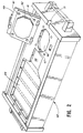
- Figure 2 is a perspective view of part of a magnetic separation device used with the apparatus of Figure 1.
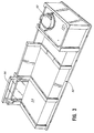
- Figure 3 is a perspective view of another part of magnetic separator used with the apparatus of Figure 1.
- Figure 4 is a perspective view of the separation system in operating position.
- Figure 5 is a plan view of a compound magnet used in the magnetic separator of Figures 2-4.
- Figure 6 is an end view of the magnet of Figure 5.
- Figure 7 is an end view of a second compound magnet used in the magnetic separator of Figures 2-4.
- a disposable system 10 for separating an individual population or populations of cells from a heterogeneous cell mixture.
- Cell concentrator portion 12 which may be used withthis invention is schematically shown and may be of a design as shown in U.S. Patent Nos. 4,379,452 or 4,410,026, or may be any cell concentrator member usable in any known apparatus for the concentrating of cells.
- the CS3000 T.M. separation system sold by Baxter Healthcare Corporation may be used, or the Autopheresis-C T.M. separation system, sold also by Baxter Healthcare Corporation, or any other desired, similar device, may be used.
- a desired population of cells may be provided, for example lymphocytes, separated in concentrator system 12 from whole blood.
- the lymphocytes perhaps mixed with other white blood cells, pass through flexible conduit 16 into flexible, collapsible container 18 of generally conventional design, which contains the particle means of micron-sized particles including a paramagnetic material such as ferric oxide, coated with plastic such as polymethyl methacrylate, which, in turn, is further coated with an antibody or other cell bonding agent to the specific marker proteins in the cell wall of a given category of leukocytes, so that the leukocytes and particles 20 selectively bond to each other, to the exclusion of the remaining leukocytes and other cells.
- a paramagnetic material such as ferric oxide
- plastic such as polymethyl methacrylate
- the apparatus of this invention also carries flexible tubing 22 which communicates between flexible, collapsible container 18 and a flexible collapsible container 24 communicating with tubing 22 at one end and communicating with an outlet tubing 26 at this other end.
- Tubing 26 branches into tubings 28, 30 each of which connects to another flexible, collapsible container 32, 34.
- cell concentrator portion 12 is preferably integrally connected to flexible container 18, the connection may be made by a conventional sterile connector system, if desired.
- the particles 20 may be stored either outside of container 18 and connected with a sterile connector system, or they may be placed in a frangible container inside of bag 18 with the container being breakable on use so that the particles 20 do not have an excessive amount of time to interact with the bag walls, in the event that some adhesion may take place there. Of course, the particles 20 may reside freely within the bag if the particles do not interact with the bag wall.
- the primary, cell-containing container 18 may be sealed by heat sealing of line 16 and by operation of clamp 36 (although clamp 36 may be closed at an earlier stage of the operation). If the microbeads or particles 20 are not already added to the container, they may be so added at this time, followed by gentle mixing of the contents of the primary container: specifically, the cells and the microbeads or particles. At this time, bonding takes place between the particular cells selected and the antibody coating of the particles or microbeads 20.
- containers 18 and 24 are placed into magnetic separator 40, which is shown in various aspects in Figures 2-7.
- Separator 40 carries upper base member 42 which carries magnet assemblies 44, 46.
- Upper rotatable, hinged presser member 49 comprises a flat undersurface portion 50, and carried by base 42, overlying in its closed position magnet 46.
- Upper base member 42 thus provides two spaces, respectively against magnet 44 and magnet 46, which are respectively proportioned to receive bag 18 and bag 24.
- Channel 47 and space 48 provide room for tubing 22, while channel 51 is provided to receive tubing 26.
- lower base member 52 is proportioned to receive upper base member 42 in cradle area 54 so that tubing 26 can be connected to roller pump assembly 53 for controlled pumping flow of cells out of bag 18, through intermediate bag 24, and into one or the other of containers 32 or 34.
- Hinged cover 56 is positioned to be brought down on top of bag 18 as installed in upper base member 42.
- Upper rotatable hinged presser member 49 presses down in similar manner on flexible chamber 24.
- the purpose of particularly presser member 49 is to provide precise definition of the thickness of the flow path of chamber 24 during processing to cause the flow path across the associated magnet 46 to be of very shallow depth, for example, about 1.27 mm (0.05 inch).
- magnet 44 is positioned to associate with chamber 18.
- the magnets 44 and 46 are designed to provide suitably configured magnet fields to capture and retain paramagnetic particles passing through the containers positioned thereon, respectively containers 18 and 24.
- magnetic 44 will possess a greatermagnetic field reach than magnetic 46 in order to capture a larger percentage of particles. This places the cells passing therethrough into a position to be strongly influenced by the fields generated by magnets 44, 46. Thus, those cells bonded to magnetic beads will be retained adjacent one or the other of the magnets.
- upper base member 42 may be refrigerated to a temperature on the order of 4° C. prior to use.
- the cold magnets keep the cells cold during operation, as well as providing some increase in magnetic field strength.
- the cold cells are less active and better preserved.
- non-specific cell interactions with the paramagnetic beads can be reduced. For example, phagocytes present are less active in ingesting available beads when kept at low temperatures.
- clamp 36 When containers 18, 24 are lying on magnets 44, 46, clamp 36 may be opened, and pivotable pressure member 56 may be gently closed to press the container 18 flat and to press the cells and their carrier liquids out of bag 18, which rests upon magnet 44.
- Presser 56 may also contain magnetizable metal strips that are sized and positioned so that they are magnetically pulled to the magnet 44 in a way such that the plastic bag 18 is squeezed and the efficient flow from the bag is controlled and relatively constant.
- the roller pump 53 may be activated to cause the cells and their carrier liquids to flow out of bag 18.
- the magnetic field from magnet 44 attracts the particles or microbeads 20, and the cells to which they are bonded, causing such microbeads 20 to be generally firmly affixed against the inner wall 57 (Fig. 6) of bag 18 that is closest to magnet 44, holding the particles 20 and their attached cells as the remaining cells and suspension liquid pass through tubing 22 out of bag 18.
- Hinged presser member 49 contains four metal bolts 81 that are sized to hold the presser member 49 in place with the proper spacing and mount of magnetic force.
- the surface 50 of presser member 49 is precisely machined to precisely define the thickness of the flow path through container 24. The shallow depth of this flow path causes any particles or microbeads present to drift into the influence of the magnetic field of magnet 46, to be retained on the inner wall 59 of container 24 as the remaining cells and liquid flow by, out of container 24, through tubing 26, into bag 32, for example. In such a circumstance, tubing 30 may be clamped off to keep bag 34 empty.
- a small amount of cell-compatible suspension liquid may be passed through the system, via sterile connector port 61, priming line 33, or another integrally connected container, to flush the remaining cells which are unattached to paramagnetic particles through the system into bag 32.
- tubing 28 may be closed, and tubing 30 opened by conventional clamp means.
- the system may be removed from the field of influence of magnets 44, 46, and, more suspension/solution may be passed into container 18, to flush the cells which are bound to particles 20 through tubing 22, through chamber 24, picking up any bound cells retained there, and into container 34.
- containers 32, 34 may be separated from the system by sealing and severing of tubings 28, 30 in conventional manner, with the desired particular population of cells being separated out from the main body of cells, and placed in separate container 34 for separate use.
- magnet 44 is designed to possess a greater magnetic field reach than magnet 46.
- this magnetic field reach is at least equal to about three-quarters of the width of the container 18, and more preferably substantially equivalent to such width. This ensures that a majority of the paramagnetic particles within container 18 are captured by the magnetic field and drawn to the surface of magnet 44.
- magnet 44 will have a magnetic field reach of from about 12.7 to 25.4 mm (one-half to one inch), preferably, 12.7 to 19.05 mm (one-half to three-quaters of an inch).
- Magnet assembly 46 may be made of similar construction. Magnet assembly 44 is shown to comprise a stack of bar magnets 64 which are separated by, and in contact with, steel pole pieces 66. As a particular advantageous feature, the like poles of adjacent bar magnets 64 in the stack face each other and particular pole piece separating them. This is demonstrated by the letters "N" and "S", each of which indicate the combined north poles or south poles of the respective magnets which are facing each other.
- the bar magnets 64 define long sides 68 and ends 70, and north and south poles of the bar magnets being defined along an opposed pair of long sides as shown in Figure 5.
- the bar magnets are made of a high magnetism alloy of neodymium, iron and boron.
- the face 72 of the magnet assembly shown rests in use against an outer wall of bag 18 so that the magnetic field from magnet assembly 44 passes into container 18, for retention of particles 20.
- magnet assembly 44 an end view of magnet assembly 44 is shown, with face 72 being the face that is displayed in Figure 5.
- magnets 64 separated by pole pieces 66, rest upon a non-magnetizable aluminum plate 74 or the like, to support the respective magnets and pole pieces.
- pole pieces 66 each define an angled groove 76 along parallel end faces which are spaced from bar magnets 64, and which are opposed to face 72 of the assembly 44, which face is the fixed location for retaining the particle/cell conjugate formed through the paramagnetic particles as in this invention.
- the bar magnets 64, pole pieces 66, and support plate 74 may be bonded together in any conventional manner with non-magnetic cement, or making use of appropriate clamps or retention straps.
- Appropriate magnets for use herein may be obtained from the Crucible Magnetics Co. of Elizabethtown, Kentucky.
- Magnet assembly 44 contains magnets 64 that are 12.7 mm (.50 inch) thick and pole pieces 66 that are 6.35 mm (.25 inch) thick. This generates a magnetic field that has local maxima of 7000 to 9100 gauss (average 8300 gauss) at the surface of the magnet and which decreases to 1100 to 1700 gauss (average 1400 gauss) at a distance of 1 cm. from the magnet surface.
- This magnet assembly gives both a relatively strong magnetic holding force at the magnet surface and a relatively good magnetic "reach out” force to capture beads some distance (up to 25.4 mm (1")) from the magnet surface.
- Magnet assembly 46 contains magnets 64 that are 6.35 mm (.25 inch) thick and pole pieces 66 that are 2.54 mm (0.1 inch) thick. This generates a magnetic field that has local maxima at the magnet surface ranging from 7300 to 8000 gauss and which decreases to 80 to 500 gauss at a distance of 1 cm from the magnet surface. Compared to magnet assembly 44, magnet assembly 46 has a stronger magnetic holding force at the magnet surface, but has less magnetic "reach out” force and thus has a shallower magnetic field.
- the second flexible container 24 is designed to take advantage of the particular magnetic field of magnet 46. First container 18 is shown to rest on magnet assembly 44 for cell separation.
- the system isolates in an aseptic, simplified manner, a particular subclass of concentrated cells, which may be separated as shown for any desired purpose.
- This example illustrates a specific application of the apparatus and method of this invention in the separation of T-helper/inducer lymphocyte cells collected from whole blood.
- HBSS Hanks Balanced Salt Solution
- phosphate buffered saline aliquots of phosphate buffered saline.
- the beads were then suspended in 20 ml. of 50 millimolar dithiothreitol in sodium acetate (0.1 Ml buffer, pH 4.5) and incubated with end-over-end rotation for 30 minutes at 4° C. to form the thiol derivative.
- the bead preparation was then washed five times in phosphate buffered saline, collecting the beads with a magnet after each wash. Finally, the beads were resuspended in 20 ml. of phosphate buffered saline.
- Mouse anti-Leu 3a antibody (type CD4 antibody-2mg. in 2 ml. phosphate buffered saline) was added to 0.1 ml. of 20mM SPDP in absolute ethanol. The mixture was dialyzed overnight against 500 ml. of phosphate buffered saline.
- the resulting antibody solution was added to the derivitized bead suspension in a 50 ml. glass centrifuge tube. The tube was rotated end-over-end overnight at room temperature to cause coupling of the antibody to the beads. Then, the beads were washed five times with phosphate buffered saline and resuspended in 30 ml. of phosphate buffered saline.
- the beads because of their dithiothreitol treatment, carry bound sulfhydryl active groups. Accordingly, upon being brought together, the antibody and the beads become chemically bonded together through a disulfide linkage resulting from a condensation reaction, with 2-thiolpyridine being split off as a by-product.
- roller pump 53 was actuated to pump at a rate of 10 ml. of fluid per minute into collection bag 32. Any bead-cell conjugates that escaped from bag 18 were subjected to the influence of secondary magnet 46 in bag 24, to be captured on the inner surface of chamber 24 adjacent that magnet, while cells which were not so bonded to the beads flowed out with fluids to collection bag 32.
- bag 18 and container 24 of fluids After substantial emptying of bag 18 and container 24 of fluids, the bead-cell conjugate in bag 18 was resuspended in 100 ml. of physiological saline, while removing bag 18 and container 24 from their seating on the respective magnets, and closing flow through tubing 26 while so doing. Following this, bag 18 and container 24 were reinstalled in their positions on upper magnet tray 42, and the suspending saline solution withdrawn from bag 18 by roller pump 53, as before, through tubing 26 into collection bag 32, along with any remaining cells which were not bonded to a paramagnetic bead.
- bag 18 and container 24 were once again removed from the influence of the magnets, after closing off flow through tubing 26.
- the bead-cell conjugate in bag 18 and container 24 was resuspended in 100 ml. of physiological saline containing 25mM dithiothreitol to break the bond between cells and beads.
- Bag 18 and container 24 were placed on a rotator at 4° C for 20 minutes.
- bag 18 and container 24 were connected to a 1 liter Fenwal PL269 tissue culture flask (symbolized in Fig. 1 as container 34).
- bag 18 and container 24 were reinstalled in upper tray 42, the hinged presser plates were closed, and the bag fluid contents were flushed into the tissue culture flask 34 while the paramagnetic bead particles remain trapped adjacent the magnets.
- the free lymphocytes which are positive to the action of CD4 antibody have been separated from other cells in the mixture, and are provided in isolated form in the tissue culture flask 34, or, if desired, a blood bag 34 as specifically shown in Fig. 1.
- Residual cells in the separation set downstream from bag 24 are also flushed into flask or bag 34 with more physiological saline.
- the cells in flask 34 may be collected by centrifugation and resuspended in 100 ml.
- RPMI 1640 tissue culture medium containing supplemental glutamine and placed in a carbon dioxide incubator for subsequent further study.
- bone marrow cells generally, cells of the following types: B-lymphoma, neuroblastoma, breast cancer, or leukemia cells, when such cells express a tumor associated antigen on their surface recognizable by a biological attached to the bead particle surface.
- the process may be used or purifying bone marrow cells prior to autologous bone marrow transplant.
- the bone marrow may be processed through a conventional cell separator to extract a mononuclear cell preparation therefrom.
- This mononuclear cell preparation may be incubated with a panel of mouse-derived monoclonal antibodies against the tumor cells, washed to remove excess antibody, and then incubated with paramagnetic beads as described in Example 1, coated with goat antimouse antibody to selectively bind the tumor cell to the bead.
- the tumor cell is then removed as in Example 1, using a magnetic separator of the type disclosed.
- T-lymphocytes may be removed from the mononuclear cell preparation described in Example 2 before an allogenic transplant to prevent Graft vs. Host Disease.
- This may be used in the case where bone marrow grafts are provided for the treatment of cancer, or for reconstitution of the bone marrow after exposure to radiation apart from cancer treatment.
- the Mononuclear cell preparation from the bone marrow is treated with a mouse monoclonal antibody (for example, anti CD3) to tag the T-lymphocyte cells for binding by the goat antimouse antibody coated beads.
- a mouse monoclonal antibody for example, anti CD3
- the mononuclear cell preparation previously prepared from bone marrow as in Example 2 may also be treated in a manner similar to that described above, making use of a mouse monoclonal antibody bonded to the paramagnetic beads to allow the selection of pluripotent stems cells from the mononuclear cell preparation.
- the isolated stem cells can thus be used for bone marrow transplant. This approach could be used to provide for autologous bone marrow transplants which are substantially free of tumor cells, while suppressing Graft vs. Host Disease. Such isolated stem cells could also be used for gene therapy, in which genes are inserted into the stem cells prior to their implantation as a bone marrow transplant.
- liver hepatocytes or insulin secreting pancreatic beta cells may be isolated and thereafter cultured in an appropriate culture medium to expand the cells for use in organ transplantation.
- cytotoxic T-lymphocytes By a process similar to that of Example 1, making use of an appropriate monoclonal antibody, specific populations of cytotoxic T-lymphocytes may be selected, such as tetanus-toxoid primed lymphocyte cells. These cells can be separated by an analogous technique similar to that of Example 1, manipulated in vitro and transfused to effect targeting of the cytotoxic cells to specific B-lymphocytes which mediate autoimmune disease (for example, Myasthenia Gravis). In this way, the disease mediating cells could be destroyed in situ.
- autoimmune disease for example, Myasthenia Gravis
Landscapes
- Health & Medical Sciences (AREA)
- Life Sciences & Earth Sciences (AREA)
- Engineering & Computer Science (AREA)
- Immunology (AREA)
- Biomedical Technology (AREA)
- Hematology (AREA)
- Heart & Thoracic Surgery (AREA)
- Vascular Medicine (AREA)
- General Health & Medical Sciences (AREA)
- Urology & Nephrology (AREA)
- Chemical & Material Sciences (AREA)
- Molecular Biology (AREA)
- Anesthesiology (AREA)
- Animal Behavior & Ethology (AREA)
- Public Health (AREA)
- Veterinary Medicine (AREA)
- Cell Biology (AREA)
- Cardiology (AREA)
- Microbiology (AREA)
- General Physics & Mathematics (AREA)
- Food Science & Technology (AREA)
- Medicinal Chemistry (AREA)
- Physics & Mathematics (AREA)
- Analytical Chemistry (AREA)
- Biochemistry (AREA)
- Biotechnology (AREA)
- Pathology (AREA)
- Tropical Medicine & Parasitology (AREA)
- Zoology (AREA)
- Virology (AREA)
- Apparatus Associated With Microorganisms And Enzymes (AREA)
- Micro-Organisms Or Cultivation Processes Thereof (AREA)
Abstract
Description
- The present invention concerns a novel apparatus and method for separating a specific cell population from a heterogeneous cell mixture.
- In the field of cell separation, it is common to separate cells from plasma in blood and also to separate by centrifugation various types of cells such as red cells from white cells and the like. However, there is often a need to separate cells which are only slightly different from the other cells in a suspension thereof. If the cells are of nearly equal specific gravity, they may not be separated by centrifugation.
- For example, it may be desirable to isolate various types of leukocytes from a bone marrow concentrate or a peripheral blood stem cell concentrate. It may be desirable to perform selective separation of neuroblastoma cells from a bone marrow concentrate. It may be desirable to selectively separate specific T-lymphocyte subset populations (helper-inducer or suppressor-cytotoxic T-lymphocytes) from a lymphocyte concentrate that is prepared using a blood cell separator.
- Additionally, it may be desirable to selectively separate precursors of lymphokine activated killer (LAK) cells, tumor infiltration lymphocyte (TIL) cells, or activated killer monocytes, from lymphocyte or monocyte cell concentrates or from a tissue cell preparation.
- US-A-4710472 discloses a device for removing magnetic bead-coated cells from a heterogeneous cell mixture using magnetic means.
- Magnetic separations of individual subsets of cells from larger populations in significant quantities become possible. This, in turn, opens up new vistas of research and therapeutic techniques, making use of the purified cell populations which may be obtained.
- The pre-characterising parts of
claims 1 and 20 contain features present in the disclosure of US-A-4710472, and the distinguishing features of the present invention are set out in the characterising parts ofclaims 1 and 20. - Another current practice in the field for cell separation utilizes hollow fiber, flat sheet membrane or packed bed bead or particle matrix materials with physically adsorbed or covalently attached chemicals or biochemicals for the selective cell separation from whole blood or the like. These devices are designed to allow continuous whole blood or blood component inflow and return. Since these devices operate at normal blood flow rates under conditions in which the concentration of desired cells can be very low compared with other cell types, the separation process is often not efficient.
- In this invention, an apparatus and a method are provided for selective separation of a specific cell population from a heterogeneous cell mixture. In a preferred embodiment, the heterogenous cell mixture may first be subjected to a means for obtaining a selective cell concentrate from the heterogeneous cell mixture by separating the selective cell concentrate based upon the physical properties of the concentrate. The selective cell concentrate is used with the apparatus and method embodying the invention. Specifically, centrifugation may be used as a first separation step. There are many different types of cell centrifuge systems for the separation of desired types of cells.
- In the preferred embodiment, a flexible, collapsible, aseptically sealed container is provided, having particle means inside, with the particle means preferably having chemically covalently attached thereto a substance capable of binding to the desired cells only, to the exclusion of other cells. Examples of such a covalently bonded substance may include antibodies, antigens, proteins, glycoproteins, polysaccharides, or lipopolysaccharides. The particle means to be in long term contact with the container walls or the like.
- Means are provided for intimately contacting either the heterogenous cell mixture or the cell concentrate with the particle means within the container. This may simply be a flexible, aseptic conduit system which communicates between the site of formation of the cell mixture orconcentrate and the container which has the particle means. Incubation of the cell mixture or concentrate with the particle means may then be permitted, to cause selective binding of a specific cell population from the cell concentrate to the particles, creating a particle/cell conjugate.
- Then, since the new particle/cell conjugate will have significantly different properties from the remainder of the cells, it becomes an easy matter to separate them from other cells, by centrifugation, for example. Preferably, one may use particles which are paramagnetic, then effecting separation using magnetic members.
- The initial cell fluid volume may remain within the container during the incubation period, when binding to the particles takes place. Also, means may be provided for introducing additional volume of the cell mixture or concentrate into the container during the incubation period.
- After separation of the particle/cell conjugate from other cells, as described above, one may separate the specific cell population from the particles or vice versa, for example by eliminating the bond between the particles and the cells in known manner, so that a purified, selected population of cells may be provided for further use. Alternatively, the unbound cells may be the desired cells, being removed from the particle/cell conjugates.
- When the particles are paramagnetic, the particle/cell conjugate may be retained in a fixed location by action of the magnetic members, as remaining, unbound portions of the cell concentrate are removed from the location.
- The magnetic members which retain the particle/cell conjugate define first and second spaced magnetic members, one being downstream of the other, so that the second, downstream, spaced magnet member can pick up any bound particle/cell conjugate that is lost by the first magnet member, so that no particle/cell conjugate goes downstream with remaining cells.
- The magnetic members may be positioned adjacent to means for carrying and positioning the flexible, collapsible container which carries the particle/cell conjugate, to permit at least one inner wall portion of the container to be within the magnetic field of a magnetic member. Thus, this inner wall portion serves as the fixed location at which the particle/cell conjugate is retained.
- Flat-pressing means may also be provided, to press the collapsible container flat while the inner wall portion is within the magnetic field, to facilitate separation of the particle/cell conjugate from the remainder of the cell concentrate.
- Specifically, the second magnetic member possesses a magnetic field that is shallower (ie, less extensive in distance) than the magnetic field of the first magnetic member, but stronger adjacent the magnet surface for stronger paramagnetic particle retention. Preferably, the magnetic reach of the first magnetic member is substantially equivalent to the width of the fluid container being placed thereon. This ensures that the majority of the paramagnetic particles in the container will fall within the reach of the magnetic field and be drawn to the magnet surface.
- It is also preferred for the container which contains the particle means to be aseptically connected to a flexible, multiple-chamber insert member for a blood cell separation centrifuge. Such an insert member may be the disposable, blood-carrying, inner, flexible portion typically used in such a centrifuge. It may be integrally aseptically connected to the container, so that freshly collected blood cells may be aseptically transferred from the insert member to the container having the particle means, without any need of forming a sterile connection therebetween. This greatly simplifies the use, and also increases the likelihood that there is not breach of aseptic conditions.
- Also, a first container having the particle means may be aseptically connected to further flexible, collapsible container means, for receiving processed cells from the first container which contains the paramagnetic particle means, or particle means of another type, if desired. Typically, a second flexible, collapsible container is sealingly, aseptically connected to and positioned between the first container described above and the further collapsible container means. This may serve as a downstream catch area which is positioned against the second magnetic member described above to catch any particle/cell conjugate which escapes the first magnetic member against which the first container may be pressed during the cell separation operation. The second flexible, collapsible container may preferably be of hexagonal shape with inlet and outlet ports at opposed corners, to cause generally slow flow of cells through said second container relative to flow lines connected thereto. The flow line diameter is typically no more than one-fourth the width of the second container. Also the flow path, particularly through the second container during magnetic separation, should be of a very shallow depth, typically 0.508 mm to 2.54 mm (0.02 to 0.1 inch).
- Further in accordance with a preferred embodiment, one may practice a method which includes the following steps. Blood from the patient may either be collected in a first container or the patient may be connected to a blood separation centrifuge, the centrifuge being operated to form a cell concentrate which is collected in the first container. The first container is sealed. If the particle means are not already in the container, they may be placed in the container in some aseptic manner, or an inner container positioned within the container may be broken from outside of the container to cause their release within the container. Thus the cells and the particle means are mixed. Then, the primary container is connected, if not already integrally connected, to the inlet of a clamped separation set. The primary container and a desired secondary chamber between the primary container and the rest of the separation set are both placed in magnetic separator means. A primary magnet attracts the particles of the particle means, which by now are bonded to the desired cells, to retain the particle means in the primary bag as the remaining contents of the bag flow toward the separation set. The same principle takes place in the secondary chamber under the influence of a secondary magnet, to eliminate or greatly reduce the possibility of any of the particle means and attached cells flowing downstream with the rest of the contents of the primary container.
- A clamp is then opened and/or a pump actuated to initiate flow from the primary container through the secondary container and across the magnetic field of the secondary magnet, into storage containers of the separation set. The storage containers may then be sealed, followed by optional disconnection of the storage containers.
- Then the magnets may be removed and the adhering cells flushed, so that one or more storage containers may contain pure cell/particle conjugate, while other storage containers contain the remaining contents of the primary container. After this, a conventional process may be used to separate the particles of the particle means from their attached cells, with the cells then being separated by centrifugation or other desired means, such as filtration or magnetic separation, and sent to a container for storage of the pure cells. The means used to break the connection between the particles and the cells depends, of course, upon the specific bonding agent. For example, the particle means may be coated with a antibody for the specific desired cells, with the result that the cells bond to the particle means. Then, when the bond is to be broken, an appropriate reagent may be used to break the bond.
- An advantage of the method is use of the magnetic separating apparatus with a cell concentrate in a batch process. In the cell concentrate the specific cell population to be separated is present at higher concentration, which tends to favor separation kinetics. Another advantage is that numerous unwanted blood cell types, in the situation where blood cells are being separated, may have already been greatly reduced in number by the preliminary, typically centrifugal cell separation process, to reduce non-specific cell reactions. For example, the collection of a lymphocyte cell concentration with minimal red blood cell, platelet, and granulocyte contamination may be effected using a blood cell separator.
- Additionally, introduction of the particles of the particle means to a cell concentrate under the conditions described above allows incubation to take place at constant volume conditions under storage within the container having the particle means. Thus, the incubation solution composition can be configured to more easily obtain favorable final incubation conditions for formation of the particle/cell conjugate. These conditions may then be optimized for a specific purpose in a way which is far more versatile than otherwise.
- The subsequent separation of the particle/cell conjugate is also advantageously achieved, with separation times being faster, and fewer cell types in the original concentrate providing a final product with fewer non-desired contaminating cells.
- As previously stated, the material which is covalently attached to the particle means may be, for example, an antibody, antigen, protein, glycoprotein, polysaccharide, lipopolysaccharide. The material may also be a nucleic acid, a lipid molecule, or a synthetic or chemically modified component of such a substance which shows a selective binding affinity for the cell population to be separated. The methods used for the chemical covalent attachment of such are known and used in the production of coupled matrix material for affinity chromatography and other selective adsorption applications. Examples of such techniques of covalent attachment to sepharose, gelating, or other beads may be seen from the following articles: Habeeb, "A Novel Preparation of Immunoadsorbents," Biochimica et Biophysica Acta, 673 (1981) 527-538; Cambier, et al., "Isolated Phosphorylcholine Binding Lymphocytes. I. Use of a Cleavable Crosslinking Reagent For Solid-Phase Adsorbent Isolation of Functional Antigen Binding Cells," Journal of Immunological Methods, 51 (1982) 209-221; and Bonnafous, et al., "Ligands Immobilized Through Cleavable Mercury-Sulfur Bonds.: Journal of Immunological Methods, 58 (1983) 93-107.
- The solution in which the particle means may be suspended can be a buffered sale solution which may contain a protein such as albumin, and is compatible with the physiological requirements of the heterogeneous cell concentrate and the biological binding material attached to the particle means. This solution may be configured in its chemical composition and properties to confer sterility to the substance which is covalently attached to the bead or particle. Furthermore, the solution may be configured in its chemical composition and properties such that when a bead or particle suspension is added to the heterogeneous cell concentrate, the properties of the resulting mixture favor the formation of the bead or particle conjugate.
- For example, the heterogeneous cell mixture or concentrate may be a bone marrow preparation in which the cells may be further concentrated in a cell concentrating centrifuge or the like. Additionally, the heterogeneous cell mixture can be a tissue derived cell suspension, or a cell concentrate prepared from peripheral blood using such centrifugal device. Examples of the latter are concentrates of platelets, lymphocytes, granulocyte, monocytes, or peripheral bone marrow stem cell preparations prepared with a blood cell separator such as the previously described CS3000 blood cell separator or Autopheresis-C device.
- The beads or particles used in the system may be selected for particular size and specific gravity properties so as to allow the subsequent separation of the beads or particle/cel conjugate from the unconjugated cells in the heterogeneous cell concentrate using the centrifugal capabilities of a blood cell separator. A solution such as Ficoll-Hypaque or Percoll might be used to facilitate this separation.
- The beads or particles of the particle means may be composed of any number of different materials such as polystyrene, latex, plastic copolymers, glass, synthetically produced gel beads and the like. Preferably, such materials will possess good mechanical properties to prevent flaking or fracturing of the beads or particles, and will allow chemical covalent attachment with ease.
- It is further preferred for the beads or particles to be formed around a magnetite particle, for example, to allow separation of the bead or particle/cell conjugate using magnets, as described above. For example, particles may be produced in accordance with the methods as described in EP-A-0344270
- The typical size of the particle means used in this invention may be from about 2 to 10 microns, preferably about 3 to 5 microns. The particles may be added in a liquid suspension, forming a typically dark sludge-like material.
- On the order of 10 ml. of such liquid suspension may be placed in the bag which is to receive the cells for separation typically including one hundred thousand to 20 billion particles. In the event it is undesirable for any reason for the particles to remain in the bag for an excessively long time, due, for example, to interaction with the bag wall, they may be added separately to the bag by conventional means such as using a sterile connector, or they may reside in a frangible container within the bag, to be broken when their use is desired so that they enter the bags interior from the frangible container.
- As stated above, the various containers used in this application are preferably integrally linked together in their initial manufacture so as to avoid the need for sterile connection during the processing. However, they may also be connected together with sterile connectors, numerous designs of which are well-known, for example, those of U.S. Patent No. Re. 32,056.
- The Dynal Company of Great Neck, New York manufactures paramagnetic microbeads which may be used in accordance with this invention.
- For a typical blood cell separation, the number of microbeads of the particle means used may number from about a hundred thousand to one billion. It has been found, when making use of a primary and secondary magnetic separator as described above, that the removal of microbeads and the cells attached to them from a cell suspension may be quantitative, with virtually no microbeads found in downstream effluent after passage through the magnetic separation apparatus.
- Figure 1 is a partially schematic plan view of apparatus for selectively separating cells.
- Figure 2 is a perspective view of part of a magnetic separation device used with the apparatus of Figure 1.
- Figure 3 is a perspective view of another part of magnetic separator used with the apparatus of Figure 1.
- Figure 4 is a perspective view of the separation system in operating position.
- Figure 5 is a plan view of a compound magnet used in the magnetic separator of Figures 2-4.
- Figure 6 is an end view of the magnet of Figure 5.
- Figure 7 is an end view of a second compound magnet used in the magnetic separator of Figures 2-4.
- Referring to Figure 1, a disposable system 10 is disclosed for separating an individual population or populations of cells from a heterogeneous cell mixture.
-
Cell concentrator portion 12 which may be used withthis invention is schematically shown and may be of a design as shown in U.S. Patent Nos. 4,379,452 or 4,410,026, or may be any cell concentrator member usable in any known apparatus for the concentrating of cells. For example, the CS3000T.M. separation system sold by Baxter Healthcare Corporation may be used, or the Autopheresis-CT.M. separation system, sold also by Baxter Healthcare Corporation, or any other desired, similar device, may be used. - At
outlet port 14 ofconcentrator system 12, a desired population of cells may be provided, for example lymphocytes, separated inconcentrator system 12 from whole blood. The lymphocytes, perhaps mixed with other white blood cells, pass throughflexible conduit 16 into flexible,collapsible container 18 of generally conventional design, which contains the particle means of micron-sized particles including a paramagnetic material such as ferric oxide, coated with plastic such as polymethyl methacrylate, which, in turn, is further coated with an antibody or other cell bonding agent to the specific marker proteins in the cell wall of a given category of leukocytes, so that the leukocytes andparticles 20 selectively bond to each other, to the exclusion of the remaining leukocytes and other cells. - The apparatus of this invention also carries
flexible tubing 22 which communicates between flexible,collapsible container 18 and a flexiblecollapsible container 24 communicating withtubing 22 at one end and communicating with anoutlet tubing 26 at this other end.Tubing 26 branches intotubings collapsible container - While
cell concentrator portion 12 is preferably integrally connected toflexible container 18, the connection may be made by a conventional sterile connector system, if desired. Additionally, theparticles 20 may be stored either outside ofcontainer 18 and connected with a sterile connector system, or they may be placed in a frangible container inside ofbag 18 with the container being breakable on use so that theparticles 20 do not have an excessive amount of time to interact with the bag walls, in the event that some adhesion may take place there. Of course, theparticles 20 may reside freely within the bag if the particles do not interact with the bag wall. - After the cells have been separated and concentrated in
separation apparatus 12 and conveyed tobag 18, the primary, cell-containingcontainer 18 may be sealed by heat sealing ofline 16 and by operation of clamp 36 (althoughclamp 36 may be closed at an earlier stage of the operation). If the microbeads orparticles 20 are not already added to the container, they may be so added at this time, followed by gentle mixing of the contents of the primary container: specifically, the cells and the microbeads or particles. At this time, bonding takes place between the particular cells selected and the antibody coating of the particles ormicrobeads 20. - Following this, if
container 18 is not integrally connected, as shown, with the downstream set portion of this invention beginning withchamber 24 and includingbags - Following this,
containers magnetic separator 40, which is shown in various aspects in Figures 2-7. -
Separator 40 carriesupper base member 42 which carriesmagnet assemblies presser member 49 comprises aflat undersurface portion 50, and carried bybase 42, overlying in itsclosed position magnet 46.Upper base member 42 thus provides two spaces, respectively againstmagnet 44 andmagnet 46, which are respectively proportioned to receivebag 18 andbag 24.Channel 47 andspace 48 provide room fortubing 22, whilechannel 51 is provided to receivetubing 26. - Additionally,
lower base member 52 is proportioned to receiveupper base member 42 incradle area 54 so thattubing 26 can be connected toroller pump assembly 53 for controlled pumping flow of cells out ofbag 18, throughintermediate bag 24, and into one or the other ofcontainers - Hinged
cover 56 is positioned to be brought down on top ofbag 18 as installed inupper base member 42. Upper rotatable hingedpresser member 49 presses down in similar manner onflexible chamber 24. The purpose of particularlypresser member 49 is to provide precise definition of the thickness of the flow path ofchamber 24 during processing to cause the flow path across the associatedmagnet 46 to be of very shallow depth, for example, about 1.27 mm (0.05 inch). Similarly,magnet 44 is positioned to associate withchamber 18. As will be described more fully herein, themagnets containers magnets - One advantage for using a
magnetic separator apparatus 40 having a separableupper base member 42 is thatupper base member 42 may be refrigerated to a temperature on the order of 4° C. prior to use. Thus, the cold magnets keep the cells cold during operation, as well as providing some increase in magnetic field strength. The cold cells are less active and better preserved. Also, at low temperatures, non-specific cell interactions with the paramagnetic beads can be reduced. For example, phagocytes present are less active in ingesting available beads when kept at low temperatures. - When
containers magnets pivotable pressure member 56 may be gently closed to press thecontainer 18 flat and to press the cells and their carrier liquids out ofbag 18, which rests uponmagnet 44.Presser 56 may also contain magnetizable metal strips that are sized and positioned so that they are magnetically pulled to themagnet 44 in a way such that theplastic bag 18 is squeezed and the efficient flow from the bag is controlled and relatively constant. Alternatively, theroller pump 53 may be activated to cause the cells and their carrier liquids to flow out ofbag 18. As the cells and their carrier liquids flow throughtubing 22, the magnetic field frommagnet 44 attracts the particles ormicrobeads 20, and the cells to which they are bonded, causingsuch microbeads 20 to be generally firmly affixed against the inner wall 57 (Fig. 6) ofbag 18 that is closest tomagnet 44, holding theparticles 20 and their attached cells as the remaining cells and suspension liquid pass throughtubing 22 out ofbag 18. - If any
particles 20 and attached cells escape thefirst magnet 44, they may be caught by the interaction betweencontainer 24 andsecond magnet 46, upon which it lies, being retained against inner wall 59 (Fig. 7). Even under significant flow conditions, theenlarged container 24 exhibits relatively slow flow conditions through it. Hingedpresser member 49 contains fourmetal bolts 81 that are sized to hold thepresser member 49 in place with the proper spacing and mount of magnetic force. Thesurface 50 ofpresser member 49 is precisely machined to precisely define the thickness of the flow path throughcontainer 24. The shallow depth of this flow path causes any particles or microbeads present to drift into the influence of the magnetic field ofmagnet 46, to be retained on theinner wall 59 ofcontainer 24 as the remaining cells and liquid flow by, out ofcontainer 24, throughtubing 26, intobag 32, for example. In such a circumstance,tubing 30 may be clamped off to keepbag 34 empty. - Then, when
pressure member 56 has been used to squeeze all possible liquid and cells out ofbag 18, a small amount of cell-compatible suspension liquid may be passed through the system, viasterile connector port 61, primingline 33, or another integrally connected container, to flush the remaining cells which are unattached to paramagnetic particles through the system intobag 32. - Then,
tubing 28 may be closed, andtubing 30 opened by conventional clamp means. The system may be removed from the field of influence ofmagnets container 18, to flush the cells which are bound toparticles 20 throughtubing 22, throughchamber 24, picking up any bound cells retained there, and intocontainer 34. - Then,
containers tubings separate container 34 for separate use. - As stated above,
magnet 44 is designed to possess a greater magnetic field reach thanmagnet 46. Preferably, this magnetic field reach is at least equal to about three-quarters of the width of thecontainer 18, and more preferably substantially equivalent to such width. This ensures that a majority of the paramagnetic particles withincontainer 18 are captured by the magnetic field and drawn to the surface ofmagnet 44. Accordingly,magnet 44 will have a magnetic field reach of from about 12.7 to 25.4 mm (one-half to one inch), preferably, 12.7 to 19.05 mm (one-half to three-quaters of an inch). - Typically, magnets having greater magnetic field reaches possess lower surface field strengths. One particle magnetic assembly which provides the desired magnetic field reach, but retains substantial surface field strength will be described with reference to Figures 5 and 6.
Magnet assembly 46 may be made of similar construction.Magnet assembly 44 is shown to comprise a stack ofbar magnets 64 which are separated by, and in contact with,steel pole pieces 66. As a particular advantageous feature, the like poles ofadjacent bar magnets 64 in the stack face each other and particular pole piece separating them. This is demonstrated by the letters "N" and "S", each of which indicate the combined north poles or south poles of the respective magnets which are facing each other. Thebar magnets 64 definelong sides 68 and ends 70, and north and south poles of the bar magnets being defined along an opposed pair of long sides as shown in Figure 5. Preferably, the bar magnets are made of a high magnetism alloy of neodymium, iron and boron. In Figure 5, theface 72 of the magnet assembly shown rests in use against an outer wall ofbag 18 so that the magnetic field frommagnet assembly 44 passes intocontainer 18, for retention ofparticles 20. - Turning to Figure 6, an end view of
magnet assembly 44 is shown, withface 72 being the face that is displayed in Figure 5. As shown,magnets 64, separated bypole pieces 66, rest upon anon-magnetizable aluminum plate 74 or the like, to support the respective magnets and pole pieces. - It can also be seen that
pole pieces 66 each define anangled groove 76 along parallel end faces which are spaced frombar magnets 64, and which are opposed to face 72 of theassembly 44, which face is the fixed location for retaining the particle/cell conjugate formed through the paramagnetic particles as in this invention. - The
bar magnets 64,pole pieces 66, andsupport plate 74 may be bonded together in any conventional manner with non-magnetic cement, or making use of appropriate clamps or retention straps. Appropriate magnets for use herein may be obtained from the Crucible Magnetics Co. of Elizabethtown, Kentucky.Magnet assembly 44 containsmagnets 64 that are 12.7 mm (.50 inch) thick andpole pieces 66 that are 6.35 mm (.25 inch) thick. This generates a magnetic field that has local maxima of 7000 to 9100 gauss (average 8300 gauss) at the surface of the magnet and which decreases to 1100 to 1700 gauss (average 1400 gauss) at a distance of 1 cm. from the magnet surface. This magnet assembly gives both a relatively strong magnetic holding force at the magnet surface and a relatively good magnetic "reach out" force to capture beads some distance (up to 25.4 mm (1")) from the magnet surface. -
Magnet assembly 46 containsmagnets 64 that are 6.35 mm (.25 inch) thick andpole pieces 66 that are 2.54 mm (0.1 inch) thick. This generates a magnetic field that has local maxima at the magnet surface ranging from 7300 to 8000 gauss and which decreases to 80 to 500 gauss at a distance of 1 cm from the magnet surface. Compared tomagnet assembly 44,magnet assembly 46 has a stronger magnetic holding force at the magnet surface, but has less magnetic "reach out" force and thus has a shallower magnetic field. The secondflexible container 24 is designed to take advantage of the particular magnetic field ofmagnet 46.First container 18 is shown to rest onmagnet assembly 44 for cell separation. - Accordingly, the system isolates in an aseptic, simplified manner, a particular subclass of concentrated cells, which may be separated as shown for any desired purpose.
- This example illustrates a specific application of the apparatus and method of this invention in the separation of T-helper/inducer lymphocyte cells collected from whole blood.
- Approximately 500 ml. of whole blood was collected into a standard Fenwal Sodium Citrate Double Blood Pack and divided between the two packs to give 290 ml. in each pack. Hespan Hetastarch (55 ml.) was added to each pack, and the contents mixed by gently tilting of the pack in a back and forth motion. The red cells were allowed to settle, and the plasma layer which contains mononuclear cells was transferred to a standard Fenwal 600 ml. transfer pack using a Fenwal plasma extractor and standard transfer tubing set. The transfer pack was centrifued to pellet the cells from the plasma, and the plasma was transferred to another transfer pack using the plasma extractor. The cells were resuspended by adding 80 ml. of Hanks Balanced Salt Solution (HBSS) which 10 percent Fetal Calf Serum and gentle titling of the bag back and forth. An aliquot of the cell suspension was counted in 2 percent acetic acid and used to calculate a total cell harvest of 2.8 x 10⁹ mononuclear cells for the cell suspension. After counting of the cells, an additional 100 ml. of HBSS was added to the transfer pack, and the cell suspension was mixed. One-half of the cell suspension was transferred to a second transfer pack to give a total of about 1.4 x 10⁹ mononuclear cells in 100 ml. HBSS in each bag.
- About 1 gram of paramagnetic beads (Pandex beads with amino surface functional groups) were washed five times with saline solution and resuspended in 20 ml. of saline in a 50 ml. glass test tube. Freshly prepared N-succinimidyl-3-(2-pyridyldithio) propionate (SPDP) comprising 1.0 ml. of 20 millimolar solution of SPDP and absolute ethanol, was added to the test tube. The tube was rotated end-over-end for 30 minutes at 4° C. to form 3-(2-pyridyldithio)-propionyl-derivitized beads. The beads were collected by magnet and washed five times with 20 ml. aliquots of phosphate buffered saline. The beads were then suspended in 20 ml. of 50 millimolar dithiothreitol in sodium acetate (0.1 Ml buffer, pH 4.5) and incubated with end-over-end rotation for 30 minutes at 4° C. to form the thiol derivative. The bead preparation was then washed five times in phosphate buffered saline, collecting the beads with a magnet after each wash. Finally, the beads were resuspended in 20 ml. of phosphate buffered saline.
- Mouse anti-Leu 3a antibody (type CD4 antibody-2mg. in 2 ml. phosphate buffered saline) was added to 0.1 ml. of 20mM SPDP in absolute ethanol. The mixture was dialyzed overnight against 500 ml. of phosphate buffered saline.
- The resulting antibody solution was added to the derivitized bead suspension in a 50 ml. glass centrifuge tube. The tube was rotated end-over-end overnight at room temperature to cause coupling of the antibody to the beads. Then, the beads were washed five times with phosphate buffered saline and resuspended in 30 ml. of phosphate buffered saline.
- Thus, while the created antibody carries pyridyldithio active groups, the beads, because of their dithiothreitol treatment, carry bound sulfhydryl active groups. Accordingly, upon being brought together, the antibody and the beads become chemically bonded together through a disulfide linkage resulting from a condensation reaction, with 2-thiolpyridine being split off as a by-product.
- Approximately 300 mg. of the antibody-bonded beads prepared as above (7 x 10⁹ beads) were added to each bag of cell suspension prepared as previously described, using a 20 ml. syringe with attached 21 gauge needle. The resulting suspension had about a 5 to 1 bead to cell ration, and was gently mixed, being then placed on a Cole-Parmer rotator at a setting of 4 for 30 minutes at 4° C. The bag 18 (Fig. 1) containing the bead and cell suspension was connected to a 600 ml.
Fenwal transfer pack 32 throughtubing chamber 24, as also illustrated in Fig. 1.Bag 18 was also connected through the primingline 33 of the tubing set to a 1,000 ml. bag of physiological saline solution to allow priming of the set betweencontainer 18 and theempty transfer pack 32. - After priming the resulting interconnected bags system was installed into
upper magnet tray 42 as shown particularly in Fig. 2, withbag 28 being placed inarea 44, andcontainer 24 being placed inarea 46. Theappropriate tubing 22 was stored inarea 48, passing throughchannel 47, whiletube 26 was installed inchannel 51, and threaded throughroller pump 53. Therespective magnets upper tray 42 installed on lower tray 52 (Fig. 4). - After about 5 minutes had elapsed, to allow complete bonding of the appropriate cells to the beads through the bonded CD4 antibodies, and to allow maximum capture of the resulting bead-cell conjugates at the inner surface of
bag 18adjacent magnet 44,roller pump 53 was actuated to pump at a rate of 10 ml. of fluid per minute intocollection bag 32. Any bead-cell conjugates that escaped frombag 18 were subjected to the influence ofsecondary magnet 46 inbag 24, to be captured on the inner surface ofchamber 24 adjacent that magnet, while cells which were not so bonded to the beads flowed out with fluids tocollection bag 32. - After substantial emptying of
bag 18 andcontainer 24 of fluids, the bead-cell conjugate inbag 18 was resuspended in 100 ml. of physiological saline, while removingbag 18 andcontainer 24 from their seating on the respective magnets, and closing flow throughtubing 26 while so doing. Following this,bag 18 andcontainer 24 were reinstalled in their positions onupper magnet tray 42, and the suspending saline solution withdrawn frombag 18 byroller pump 53, as before, throughtubing 26 intocollection bag 32, along with any remaining cells which were not bonded to a paramagnetic bead. - Then,
bag 18 andcontainer 24 were once again removed from the influence of the magnets, after closing off flow throughtubing 26. The bead-cell conjugate inbag 18 andcontainer 24 was resuspended in 100 ml. of physiological saline containing 25mM dithiothreitol to break the bond between cells and beads.Bag 18 andcontainer 24 were placed on a rotator at 4° C for 20 minutes. Then,bag 18 andcontainer 24 were connected to a 1 liter Fenwal PL269 tissue culture flask (symbolized in Fig. 1 as container 34). Following this,bag 18 andcontainer 24 were reinstalled inupper tray 42, the hinged presser plates were closed, and the bag fluid contents were flushed into thetissue culture flask 34 while the paramagnetic bead particles remain trapped adjacent the magnets. - Thus, the free lymphocytes which are positive to the action of CD4 antibody, have been separated from other cells in the mixture, and are provided in isolated form in the
tissue culture flask 34, or, if desired, ablood bag 34 as specifically shown in Fig. 1. - Residual cells in the separation set downstream from
bag 24 are also flushed into flask orbag 34 with more physiological saline. - The cells in
flask 34 may be collected by centrifugation and resuspended in 100 ml. RPMI 1640 tissue culture medium containing supplemental glutamine and placed in a carbon dioxide incubator for subsequent further study. - By means of a process similar to that disclosed in Example 1, there may be removed from bone marrow cells generally, cells of the following types: B-lymphoma, neuroblastoma, breast cancer, or leukemia cells, when such cells express a tumor associated antigen on their surface recognizable by a biological attached to the bead particle surface. Thus, the process may be used or purifying bone marrow cells prior to autologous bone marrow transplant.
- The bone marrow may be processed through a conventional cell separator to extract a mononuclear cell preparation therefrom. This mononuclear cell preparation may be incubated with a panel of mouse-derived monoclonal antibodies against the tumor cells, washed to remove excess antibody, and then incubated with paramagnetic beads as described in Example 1, coated with goat antimouse antibody to selectively bind the tumor cell to the bead. The tumor cell is then removed as in Example 1, using a magnetic separator of the type disclosed.
- As an alternative technique of the use of this invention, T-lymphocytes may be removed from the mononuclear cell preparation described in Example 2 before an allogenic transplant to prevent Graft vs. Host Disease. This may be used in the case where bone marrow grafts are provided for the treatment of cancer, or for reconstitution of the bone marrow after exposure to radiation apart from cancer treatment. In this case, the Mononuclear cell preparation from the bone marrow is treated with a mouse monoclonal antibody (for example, anti CD3) to tag the T-lymphocyte cells for binding by the goat antimouse antibody coated beads.
- The mononuclear cell preparation previously prepared from bone marrow as in Example 2 may also be treated in a manner similar to that described above, making use of a mouse monoclonal antibody bonded to the paramagnetic beads to allow the selection of pluripotent stems cells from the mononuclear cell preparation. The isolated stem cells can thus be used for bone marrow transplant. This approach could be used to provide for autologous bone marrow transplants which are substantially free of tumor cells, while suppressing Graft vs. Host Disease. Such isolated stem cells could also be used for gene therapy, in which genes are inserted into the stem cells prior to their implantation as a bone marrow transplant.
- By a process substantially similar to the process of Example 1, making use of an appropriate monoclonal antibody, liver hepatocytes or insulin secreting pancreatic beta cells may be isolated and thereafter cultured in an appropriate culture medium to expand the cells for use in organ transplantation.
- By a process similar to that of Example 1, making use of an appropriate monoclonal antibody, specific populations of cytotoxic T-lymphocytes may be selected, such as tetanus-toxoid primed lymphocyte cells. These cells can be separated by an analogous technique similar to that of Example 1, manipulated in vitro and transfused to effect targeting of the cytotoxic cells to specific B-lymphocytes which mediate autoimmune disease (for example, Myasthenia Gravis). In this way, the disease mediating cells could be destroyed in situ.
Claims (28)
- An apparatus for the selective separation of a specific cell population from a heterogeneous cell mixture comprising a container (18) containing particle means (20) formed from a paramagnetic material, said particle means (20) having attached thereto a substance capable of binding to the specific cell population of said cell mixture; a cell flow path (16,22), with the container (18) positioned in the flow path (16,22) for receiving the cell mixture, such that in use said cell mixture intimately contacts, and is incubated with, said particle means within said container (18) to selectively bind said specific cell population of said cell mixture to said particle means (20), thereby creating a particle/cell conjugate; and first and second magnetic members (44,46), each positioned relative to said flow path, with said second magnetic member (46) being spaced downstream from said first magnetic member (16,22), to provide respective magnetic fields at fixed locations along said flow path to retain said particle/cell conjugate in said fixed locations and allow remaining, unbound portions of said cell mixture to be removed from said locations (44), characterised in that said second magnetic member (46) provides a shallower magnetic field at its associated location, but has a stronger magnetic holding force at its surface than the first magnetic member (44).
- The apparatus of Claim 1, in which said container (18) is a flexible, collapsible container.
- The apparatus of any preceding claim, comprising at least a second container (24) downstream of the first container (18), the second container (24) being flexible and collapsible.
- The apparatus of claim 3 in which said second container (24) comprises inlet and outlet ports at opposed ends thereof, the cross sectional area of said inlet and outlet ports being no more than one-quarter of the cross sectional area of said second container (24).
- The apparatus of Claim 4 in which said second container (24) is of hexagonal shape, said inlet and outlet ports being positioned at opposed corners thereof.
- The apparatus of Claim 3, 4 or 5, in which said second magnetic member (46) is positioned adjacent means (42) carrying said second container (24), whereby at least one inner wall portion (59) of said second container (24) is within the magnetic field of said second magnetic member (46), said inner wall portion (59) being a said fixed location.
- The apparatus of Claim 6 including flat-pressing means (49) to press said collapsible second container (24) flat while said inner wall portion (59) of said second container (24) is within the magnetic field of the second magnetic member (46) to provide a cell flow path thickness of 0.5 to 2.6 mm (0.02 to 0.1 inch) in said second container (24) to facilitate separation of said particle/cell conjugate from the remainder of said cell mixture.
- The apparatus of any preceding claim, wherein the first magnetic member (44) is positioned adjacent means (42) carrying the first container, whereby an inner wall portion (57) of the first container (18) is within the magnetic field of said first magnetic member (44), said inner wall portion (57) of the first container (18) being a said fixed location.
- The apparatus of any one of Claims 3 to 8 in which said second container (24) is sealingly and aseptically connected to the first container (18), said first magnet member (44) being positioned against said the first container (18) and said second magnet member (46) being positioned against said second container (24).
- The apparatus of any preceding claim, comprising a collapsible receptacle (32) downstream of the first container (18).
- The apparatus of Claim 10 wherein the first container (18) is aseptically connected to said receptacle (32), whereby the receptacle (32) is positioned to receive processed cells from the first container (18) without the need of forming a sterile connection therebetween.
- The apparatus of Claim 10 or 11, wherein said second container (24) is sealingly and aseptically connected to and positioned between said first container (18) and said receptacle (32).
- The apparatus of any preceding claim, comprising a fraction container for use with a cell mixture separating means (12), the fraction container being positioned upstream of the first container (18).
- The apparatus of Claim 13, wherein said cell mixture is blood and said fraction container is a flexible, multiple-chamber insert means for a blood cell separation centrifuge, the first container (18) being aseptically connected to the insert means to enable a concentrated fraction of freshly collected blood cells to be aseptically transferred from said insert means to the first container (18) without need of forming a sterile connection therebetween.
- The apparatus of any preceding claim wherein said first magnetic means (44) possesses a magnetic field having a reach substantially equivalent to the width of the first container (18).
- The apparatus of Claim 15 wherein said first magnet (44) possesses a magnetic field having a reach of from about one-half an inch to about one inch (1.2 to 2.6 cm).
- The apparatus of Claim 15 or 16 wherein said first magnetic member (44) possesses a magnetic field having a reach of from about one-half to about three quarters of an inch (1.2 to 1.9 cm).
- The apparatus of any one of Claims 1 to 17, in which said paramagnetic particle means (20) carry on their surfaces a specific antibody to cells selected from the group consisting of B-lymphoma, neuroblastoma, breast cancer, leukaemia, T-lymphocytes, and pluripotent stem cells, or are coated with a specific antibody to cells selected from the group consisting of liver hepatocytes and insulin secreting pancreatic beta cells.
- The apparatus Claim 18, in which said paramagnetic particle means (20) carry on their surfaces a specific antibody to a specific population of cytotoxic T-lymphocytes.
- A method for the selective separation of a specific population of cells from a mixture of cells, the method comprising (a) mixing the cell mixture with paramagnetic particle means (20) in a container (18), the particle means (20) having attached thereto a substance capable of binding to the specific cell population of the mixture only, (b) exposing the container (18) to a magnetic field to immobilize said particle means (20) and the specific population of cells bound thereto, and (c) flowing unbound cells to first storage container means (32), whereby the first storage container means (32) receives cells not bound to said particle means (20), characterised by flowing cells from the first container (18) to a second container (24) at step (b), while exposing the first container to a first magnetic field, and exposing the second container (24) to a second magnetic field which is shallower than the first magnetic field and which has a stronger magnetic holding force at the surface of its associated magnet than the first magnetic field.
- A method according to Claim 20, wherein the magnetic field reach of the first magnet (44) is substantially equivalent to the width of said first container (18).
- A method according to Claim 20 or 21, wherein the cell mixture is a blood fraction, and further comprising the steps of centrifuging whole blood to separate out the fraction, collecting the blood fraction in the first container (18) and sealing said first container (18) from the centrifuge.
- A method according to Claim 20, 21 or 22, further comprising the steps of positioning said first and second magnets (44,46) against said first and second containers (18,24) respectively in order to expose the containers (18,24) to the magnetic fields.
- A method according to any one of Claims 20 to 23, further comprising stopping flow between said second container (24) and said first storage container means (32); removing said first and second containers (18,24) from the magnetic field of the respective magnet (44,46) and flowing the specific cell population, (20) from said first and second containers (18,24) into a second storage container means (34).
- The method of Claim 24, wherein the cells are bound to the paramagnetic particle means (20) when they are flowed from the containers (18,24) into the second storage container means (34).
- The method of Claim 24, further comprising disconnecting fluid communication between said second container (24) and the first storage container means (32), removing the binding connections between the cells of the specific population and the paramagnetic particle means (20) so that the specific cell population is no longer bound to the particle means (20), and flowing the cell population into said second storage container means (34) while the first and second containers (18,24) are under the influence of said magnetic fields, whereby said particle means (20) are prevented from flowing with said cells into the second storage container means (34), thereby separating the cells from the particle means.
- The method of any one of Claims 20 to 26 in which said mixture of cells placed in the first container having paramegnetic particle means is a preparation of mononuclear cells previously separated from bone marrow.
- The method of any one of Claims 20 to 27 when carried out using apparatus according to any one of Claims 1 to 19.
Applications Claiming Priority (5)
| Application Number | Priority Date | Filing Date | Title |
|---|---|---|---|
| US25521488A | 1988-10-11 | 1988-10-11 | |
| US39706789A | 1989-08-22 | 1989-08-22 | |
| US397067 | 1989-08-22 | ||
| PCT/US1989/004527 WO1990004019A1 (en) | 1988-10-11 | 1989-10-10 | System for magnetic affinity cell separation from cell concentrates |
| US255214 | 1999-02-22 |
Publications (2)
| Publication Number | Publication Date |
|---|---|
| EP0438520A1 EP0438520A1 (en) | 1991-07-31 |
| EP0438520B1 true EP0438520B1 (en) | 1994-08-24 |
Family
ID=26944532
Family Applications (1)
| Application Number | Title | Priority Date | Filing Date |
|---|---|---|---|
| EP89912306A Expired - Lifetime EP0438520B1 (en) | 1988-10-11 | 1989-10-10 | System for magnetic affinity cell separation from cell concentrates |
Country Status (6)
| Country | Link |
|---|---|
| EP (1) | EP0438520B1 (en) |
| JP (1) | JPH0757177B2 (en) |
| AU (1) | AU4492789A (en) |
| CA (1) | CA1335181C (en) |
| DE (1) | DE68917736T2 (en) |
| WO (1) | WO1990004019A1 (en) |
Cited By (5)
| Publication number | Priority date | Publication date | Assignee | Title |
|---|---|---|---|---|
| US7381561B2 (en) | 2002-08-27 | 2008-06-03 | Stemcells California, Inc. | Enriched central nervous system stem cell and progenitor cell populations, and methods for identifying, isolating and enriching for such populations |
| US8168393B2 (en) | 2007-02-16 | 2012-05-01 | The Brigham And Women's Hospital, Inc. | Compositions and methods for diagnosing tumors using LEDGF/p75 |
| US8425928B2 (en) | 2008-11-14 | 2013-04-23 | Viacyte, Inc. | Encapsulation of pancreatic cells derived from human pluripotent stem cells |
| US10266808B2 (en) | 2008-04-21 | 2019-04-23 | Viacyte, Inc. | Method of enriching for pancreatic endocrine cells that express chromogranin A |
| US10518021B2 (en) * | 2015-02-20 | 2019-12-31 | Terumo Bct, Inc. | Composite liquid bag system holder |
Families Citing this family (47)
| Publication number | Priority date | Publication date | Assignee | Title |
|---|---|---|---|---|
| EP0513219B1 (en) * | 1990-01-31 | 1996-04-03 | Baxter International Inc. | Flexible bag assembly for magnetic separator |
| US5372439A (en) * | 1992-12-18 | 1994-12-13 | Zebra Technologies Corporation | Thermal transfer printer with controlled ribbon feed |
| US5439586A (en) * | 1993-09-15 | 1995-08-08 | The Terry Fox Laboratory Of The British Columbia Cancer Agnecy | Magnetic filter with ordered wire array |
| JPH0780041A (en) * | 1993-09-20 | 1995-03-28 | Terumo Corp | Cell preserving bag system |
| EP0672458A3 (en) * | 1994-03-04 | 1996-02-28 | Cleveland Clinic Foundation | Method and apparatus for magnetic cytometry. |
| CA2161958C (en) * | 1994-03-14 | 2010-02-23 | Ahmad-Maher Moubayed | Method and apparatus for semi-automated cell separation |
| GB9425138D0 (en) | 1994-12-12 | 1995-02-08 | Dynal As | Isolation of nucleic acid |
| EP0819250B1 (en) * | 1995-04-06 | 2006-09-20 | Miltenyi Biotec Inc. | Multiparameter cell separation using releasable colloidal magnetic particles |
| US5998224A (en) * | 1997-05-16 | 1999-12-07 | Abbott Laboratories | Magnetically assisted binding assays utilizing a magnetically responsive reagent |
| IL124514A (en) * | 1998-05-17 | 2002-02-10 | Davidson Chaim | Method and apparatus for magnetically separating selected particles, particularly biological cells |
| US6294342B1 (en) | 1999-09-29 | 2001-09-25 | Abbott Laboratories | Magnetically assisted binding assays utilizing a magnetically responsive reagent |
| US20020058030A1 (en) * | 2000-05-03 | 2002-05-16 | Eligix, Inc. | Whole blood separator apparatus and method of use |
| GB0013658D0 (en) | 2000-06-05 | 2000-07-26 | Dynal Asa | Nucleic acid isolation |
| AU2001280959A1 (en) * | 2000-08-01 | 2002-02-13 | Carepoint Diagnostics, Inc. | Analysis of biological samples for platelet activation or coagulation activationmarkers using microparticules |
| US6984522B2 (en) | 2000-08-03 | 2006-01-10 | Regents Of The University Of Michigan | Isolation and use of solid tumor stem cells |
| DE10127068A1 (en) * | 2001-05-23 | 2002-11-28 | Bio Medical Apherese Systeme G | Apparatus for the separation of leukocytes, from blood, has a number of stations to separate marked components with magnetic particles without any adverse effects on the blood |
| WO2003042405A2 (en) | 2001-11-15 | 2003-05-22 | Children's Medical Center Corporation | Methods of isolation, expansion and differentiation of fetal stem cells from chorionic villus, amniotic fluid, and placenta and therapeutic uses thereof |
| EP1494028A1 (en) * | 2003-07-03 | 2005-01-05 | Labsoft Diagnostics AG | Immunomagnetic separation of specific target cells |
| RU2252037C1 (en) * | 2003-10-14 | 2005-05-20 | Германов Евгений Павлович | System for correcting biological fluid |
| FI20051248A7 (en) | 2005-12-02 | 2007-06-03 | Biocontrol Systems Oy | Biological component enrichment unit and enrichment method |
| US7985340B2 (en) | 2005-12-02 | 2011-07-26 | Invitrogen Dynal As | Magnetic separator |
| GB2445073A (en) * | 2006-12-18 | 2008-06-25 | Ge Healthcare Bio Sciences Ab | Cell separation device |
| ES2640216T3 (en) * | 2007-12-07 | 2017-11-02 | Miltenyi Biotec Gmbh | Systems and methods for cell processing |
| DK2283117T3 (en) | 2008-04-21 | 2014-01-20 | Viacyte Inc | PROCEDURE FOR CLEANING PANCREATIC ENDODERM CELLS DERIVED FROM HUMAN EMBRYONIC STEM CELLS |
| CN102325878A (en) | 2008-12-23 | 2012-01-18 | 斯特姆塞尔思加利福尼亚有限公司 | Targeted cell population of oligodendrocyte precursor cells and methods of preparation and use |
| EP2597153B1 (en) | 2011-11-25 | 2016-10-05 | Miltenyi Biotec GmbH | Cell separation method |
| WO2013095867A1 (en) | 2011-12-21 | 2013-06-27 | Becton, Dickinson And Company | Flow cytometric systems for sterile separation of magnetically labeled sample components |
| DE102014106603A1 (en) * | 2014-05-12 | 2015-11-12 | Verein zur Förderung von Innovationen durch Forschung, Entwicklung und Technologietransfer e.V. (Verein INNOVENT e.V.) | Method and apparatus for depleting circulating tumor cells from a cell suspension |
| CA2984884A1 (en) | 2014-05-15 | 2015-11-19 | Kellbenx Incorporated | Preparation of fetal nucleated red blood cells (nrbcs) for diagnostic testing |
| WO2016183032A1 (en) | 2015-05-08 | 2016-11-17 | Biomagnetic Solutions Llc | Apparatus and method for immunomagnetic cell separation |
| EP3397389B1 (en) * | 2015-12-29 | 2024-05-15 | Life Technologies Corporation | Method and system for separating magnetic particles from a fluid |
| GB2565664A (en) * | 2016-03-07 | 2019-02-20 | Hitachi Chemical Advanced Therapeutics Solutions Llc | A closed system for labelling and selecting live cells |
| CN118670959A (en) | 2016-04-15 | 2024-09-20 | 贝克顿·迪金森公司 | Enclosed droplet sorter and method of use |
| EP3548108B1 (en) | 2016-12-02 | 2024-01-31 | Terumo BCT, Inc. | Composite fluid separation |
| EP3427052A4 (en) * | 2017-03-27 | 2019-12-04 | Hitachi Chemical Advanced Therapeutics Solutions, LLC | CLOSED SYSTEM FOR MARKING AND SELECTING LIVING CELLS |
| TWI616526B (en) * | 2017-05-15 | 2018-03-01 | Cell separation and purification device | |
| JP7145209B2 (en) | 2017-06-14 | 2022-09-30 | ヘルムホルツ ツェントゥルム ミュンヘン ドイチェス フォルシュングスツェントゥルム フューア ゲズントハイト ウント ウムヴェルト (ゲーエムベーハー) | Methods for purifying endoderm and pancreatic endoderm cells derived from human embryonic stem cells |
| EP3785017B1 (en) * | 2018-04-27 | 2025-09-10 | Becton, Dickinson And Company | Collection systems for flow cytometrically sorted samples and methods of using the same |
| CN119269374A (en) | 2018-04-27 | 2025-01-07 | 贝克顿·迪金森公司 | Flow cytometer with closed droplet sorter with controlled aerosol content and method of use thereof |
| CN112135789B (en) | 2018-05-08 | 2023-09-08 | 生物磁性解决方案有限责任公司 | Rigid chamber for separating cells from flexible disposable bag |
| WO2020091866A1 (en) | 2018-10-30 | 2020-05-07 | Becton, Dickinson And Company | Particle sorting module with alignment window, systems and methods of use thereof |
| CN109735447B (en) * | 2019-02-20 | 2025-02-07 | 温州市怡康细胞移植技术开发有限公司 | A device and method for isolating pancreatic islet tissue |
| EP3963337A1 (en) | 2019-05-02 | 2022-03-09 | KellBenx Inc. | Filtration-based methods for preparing fetal nucleated red blood cells (nrbcs) for diagnostic testing |
| EP4055381A4 (en) * | 2019-11-05 | 2024-03-20 | Biomagnetic Solutions LLC | An improved large scale immunomagnetic separation device |
| US20210387176A1 (en) * | 2020-06-16 | 2021-12-16 | Sani-Tech West, Inc. | Closed fluid receiving and sampling container |
| CN115521896B (en) * | 2022-09-27 | 2024-06-25 | 深圳赛桥生物创新技术有限公司 | Magnetic bead removal method, device and storage medium |
| CN115524482B (en) * | 2022-09-27 | 2026-03-06 | 深圳赛桥生物创新技术有限公司 | Magnetic bead sorting methods, equipment and storage media |
Family Cites Families (6)
| Publication number | Priority date | Publication date | Assignee | Title |
|---|---|---|---|---|
| DE3200988A1 (en) * | 1982-01-14 | 1983-07-28 | Thomas A. Dr. 6900 Heidelberg Reed | METHOD AND DEVICE FOR SEPARATING ORGANIC SUBSTANCES FROM A SUSPENSION OR SOLUTION |
| US4554088A (en) * | 1983-05-12 | 1985-11-19 | Advanced Magnetics Inc. | Magnetic particles for use in separations |
| DE3444939A1 (en) * | 1984-12-08 | 1986-06-12 | Bayer Ag, 5090 Leverkusen | MAGNETIC MICROSPHERES |
| US4710472A (en) * | 1985-09-25 | 1987-12-01 | The United States Of America As Represented By The Secretary Of The Navy | Magnetic separation device |
| AU7399787A (en) * | 1986-05-16 | 1987-12-01 | Omega Medicinteknik A.B. | Method and apparatus for plasmapheresis |
| AU2613988A (en) * | 1988-01-04 | 1989-08-01 | E.I. Du Pont De Nemours And Company | Multiple stage affinity process for isolation of specific cells from a cell mixture |
-
1989
- 1989-09-28 CA CA000614111A patent/CA1335181C/en not_active Expired - Fee Related
- 1989-10-10 AU AU44927/89A patent/AU4492789A/en not_active Abandoned
- 1989-10-10 WO PCT/US1989/004527 patent/WO1990004019A1/en not_active Ceased
- 1989-10-10 JP JP1511428A patent/JPH0757177B2/en not_active Expired - Fee Related
- 1989-10-10 DE DE68917736T patent/DE68917736T2/en not_active Expired - Fee Related
- 1989-10-10 EP EP89912306A patent/EP0438520B1/en not_active Expired - Lifetime
Cited By (7)
| Publication number | Priority date | Publication date | Assignee | Title |
|---|---|---|---|---|
| US7381561B2 (en) | 2002-08-27 | 2008-06-03 | Stemcells California, Inc. | Enriched central nervous system stem cell and progenitor cell populations, and methods for identifying, isolating and enriching for such populations |
| US8168393B2 (en) | 2007-02-16 | 2012-05-01 | The Brigham And Women's Hospital, Inc. | Compositions and methods for diagnosing tumors using LEDGF/p75 |
| US10266808B2 (en) | 2008-04-21 | 2019-04-23 | Viacyte, Inc. | Method of enriching for pancreatic endocrine cells that express chromogranin A |
| US8425928B2 (en) | 2008-11-14 | 2013-04-23 | Viacyte, Inc. | Encapsulation of pancreatic cells derived from human pluripotent stem cells |
| US9132226B2 (en) | 2008-11-14 | 2015-09-15 | Viacyte, Inc. | Encapsulation of pancreatic cells derived from human pluripotent stem cells |
| US11660377B2 (en) | 2008-11-14 | 2023-05-30 | Viacyte, Inc. | Cryopreserved in vitro cell culture of human pancreatic progenitor cells |
| US10518021B2 (en) * | 2015-02-20 | 2019-12-31 | Terumo Bct, Inc. | Composite liquid bag system holder |
Also Published As
| Publication number | Publication date |
|---|---|
| JPH0757177B2 (en) | 1995-06-21 |
| EP0438520A1 (en) | 1991-07-31 |
| AU4492789A (en) | 1990-05-01 |
| DE68917736T2 (en) | 1995-05-04 |
| CA1335181C (en) | 1995-04-11 |
| JPH04500008A (en) | 1992-01-09 |
| DE68917736D1 (en) | 1994-09-29 |
| WO1990004019A1 (en) | 1990-04-19 |
Similar Documents
| Publication | Publication Date | Title |
|---|---|---|
| CA1335181C (en) | System for selective cell separation from cell concentrate | |
| US6221315B1 (en) | Apparatus for separation of biologic components from heterogeneous cell populations | |
| EP0653062B1 (en) | Continuous centrifugation process for the separation of biologic components from heterogeneous cell populations | |
| US11499977B2 (en) | Equipment and procedure for culturing, separating, and genetically modifying donor cells for reinfusion into a patient | |
| Kemsheadl et al. | Magnetic separation techniques: their application to medicine | |
| US5840502A (en) | Methods for enriching specific cell-types by density gradient centrifugation | |
| AU720285B2 (en) | Process for preparing macrophages, and kits and compositions therefore | |
| WO2001083002A2 (en) | Whole blood separator apparatus and method of use | |
| WO1987004628A1 (en) | Immunoselection method | |
| Kemshead | The immunomagnetic manipulation of bone marrow |
Legal Events
| Date | Code | Title | Description |
|---|---|---|---|
| PUAI | Public reference made under article 153(3) epc to a published international application that has entered the european phase |
Free format text: ORIGINAL CODE: 0009012 |
|
| 17P | Request for examination filed |
Effective date: 19910308 |
|
| AK | Designated contracting states |
Kind code of ref document: A1 Designated state(s): DE FR GB IT |
|
| 17Q | First examination report despatched |
Effective date: 19930426 |
|
| GRAA | (expected) grant |
Free format text: ORIGINAL CODE: 0009210 |
|
| AK | Designated contracting states |
Kind code of ref document: B1 Designated state(s): DE FR GB IT |
|
| REF | Corresponds to: |
Ref document number: 68917736 Country of ref document: DE Date of ref document: 19940929 |
|
| ITF | It: translation for a ep patent filed | ||
| ET | Fr: translation filed | ||
| PLBE | No opposition filed within time limit |
Free format text: ORIGINAL CODE: 0009261 |
|
| STAA | Information on the status of an ep patent application or granted ep patent |
Free format text: STATUS: NO OPPOSITION FILED WITHIN TIME LIMIT |
|
| 26N | No opposition filed | ||
| REG | Reference to a national code |
Ref country code: GB Ref legal event code: 732E |
|
| REG | Reference to a national code |
Ref country code: FR Ref legal event code: TP |
|
| REG | Reference to a national code |
Ref country code: GB Ref legal event code: IF02 |
|
| PGFP | Annual fee paid to national office [announced via postgrant information from national office to epo] |
Ref country code: FR Payment date: 20021104 Year of fee payment: 14 Ref country code: DE Payment date: 20021104 Year of fee payment: 14 |
|
| PGFP | Annual fee paid to national office [announced via postgrant information from national office to epo] |
Ref country code: GB Payment date: 20031001 Year of fee payment: 15 |
|
| PG25 | Lapsed in a contracting state [announced via postgrant information from national office to epo] |
Ref country code: DE Free format text: LAPSE BECAUSE OF NON-PAYMENT OF DUE FEES Effective date: 20040501 |
|
| PG25 | Lapsed in a contracting state [announced via postgrant information from national office to epo] |
Ref country code: FR Free format text: LAPSE BECAUSE OF NON-PAYMENT OF DUE FEES Effective date: 20040630 |
|
| REG | Reference to a national code |
Ref country code: FR Ref legal event code: ST |
|
| PG25 | Lapsed in a contracting state [announced via postgrant information from national office to epo] |
Ref country code: GB Free format text: LAPSE BECAUSE OF NON-PAYMENT OF DUE FEES Effective date: 20041010 |
|
| GBPC | Gb: european patent ceased through non-payment of renewal fee |
Effective date: 20041010 |
|
| PG25 | Lapsed in a contracting state [announced via postgrant information from national office to epo] |
Ref country code: IT Free format text: LAPSE BECAUSE OF NON-PAYMENT OF DUE FEES Effective date: 20051010 |