EP0438451B1 - Liquid container support and hygienic liquid dispensing system - Google Patents
Liquid container support and hygienic liquid dispensing system Download PDFInfo
- Publication number
- EP0438451B1 EP0438451B1 EP89911311A EP89911311A EP0438451B1 EP 0438451 B1 EP0438451 B1 EP 0438451B1 EP 89911311 A EP89911311 A EP 89911311A EP 89911311 A EP89911311 A EP 89911311A EP 0438451 B1 EP0438451 B1 EP 0438451B1
- Authority
- EP
- European Patent Office
- Prior art keywords
- feed tube
- container
- recess
- liquid
- reservoir
- Prior art date
- Legal status (The legal status is an assumption and is not a legal conclusion. Google has not performed a legal analysis and makes no representation as to the accuracy of the status listed.)
- Expired - Lifetime
Links
- 239000007788 liquid Substances 0.000 title claims abstract description 32
- 238000003780 insertion Methods 0.000 claims abstract description 11
- 230000037431 insertion Effects 0.000 claims abstract description 11
- 238000007789 sealing Methods 0.000 claims description 15
- 230000000295 complement effect Effects 0.000 claims description 5
- 235000020188 drinking water Nutrition 0.000 claims description 3
- 239000003651 drinking water Substances 0.000 claims description 3
- 239000012530 fluid Substances 0.000 claims description 3
- 230000002093 peripheral effect Effects 0.000 claims description 2
- 230000008878 coupling Effects 0.000 claims 1
- 238000010168 coupling process Methods 0.000 claims 1
- 238000005859 coupling reaction Methods 0.000 claims 1
- 238000001914 filtration Methods 0.000 claims 1
- XLYOFNOQVPJJNP-UHFFFAOYSA-N water Substances O XLYOFNOQVPJJNP-UHFFFAOYSA-N 0.000 description 24
- 239000011324 bead Substances 0.000 description 2
- 238000010276 construction Methods 0.000 description 2
- 230000001681 protective effect Effects 0.000 description 2
- 238000003466 welding Methods 0.000 description 2
- 235000012206 bottled water Nutrition 0.000 description 1
- 239000000356 contaminant Substances 0.000 description 1
- 238000001816 cooling Methods 0.000 description 1
- 238000010438 heat treatment Methods 0.000 description 1
- 230000013011 mating Effects 0.000 description 1
- 238000000034 method Methods 0.000 description 1
- 238000012986 modification Methods 0.000 description 1
- 230000004048 modification Effects 0.000 description 1
- 238000005057 refrigeration Methods 0.000 description 1
- 230000000284 resting effect Effects 0.000 description 1
- 238000009420 retrofitting Methods 0.000 description 1
- 238000000926 separation method Methods 0.000 description 1
- 239000000126 substance Substances 0.000 description 1
Images



Classifications
-
- B—PERFORMING OPERATIONS; TRANSPORTING
- B65—CONVEYING; PACKING; STORING; HANDLING THIN OR FILAMENTARY MATERIAL
- B65B—MACHINES, APPARATUS OR DEVICES FOR, OR METHODS OF, PACKAGING ARTICLES OR MATERIALS; UNPACKING
- B65B3/00—Packaging plastic material, semiliquids, liquids or mixed solids and liquids, in individual containers or receptacles, e.g. bags, sacks, boxes, cartons, cans, or jars
- B65B3/04—Methods of, or means for, filling the material into the containers or receptacles
- B65B3/06—Methods of, or means for, filling the material into the containers or receptacles by gravity flow
-
- B—PERFORMING OPERATIONS; TRANSPORTING
- B67—OPENING, CLOSING OR CLEANING BOTTLES, JARS OR SIMILAR CONTAINERS; LIQUID HANDLING
- B67D—DISPENSING, DELIVERING OR TRANSFERRING LIQUIDS, NOT OTHERWISE PROVIDED FOR
- B67D3/00—Apparatus or devices for controlling flow of liquids under gravity from storage containers for dispensing purposes
- B67D3/0029—Apparatus or devices for controlling flow of liquids under gravity from storage containers for dispensing purposes provided with holders for bottles or similar containers
- B67D3/0032—Apparatus or devices for controlling flow of liquids under gravity from storage containers for dispensing purposes provided with holders for bottles or similar containers the bottle or container being held upside down and provided with a closure, e.g. a cap, adapted to cooperate with a feed tube
Definitions
- the invention relates to a liquid container support and hygienic delivery system for dispensing drinking water or other potable liquid from a substantially rigid-bodied inverted container into the open upper end of a dischargeable reservoir housed within a cabinet through an opening defined in a generally cylindrical depending neck of the inverted container, comprising mounting means for embracingly supporting the depending neck of the container over the open upper end of the reservoir, and an upstanding feed tube supported so as to extend through sealing means sealingly closing the said open upper end of the reservoir and dimensioned to penetrate into the neck of the inverted container through a sealing arrangement thereof to provide a hygienic flow path for delivering liquid from the inverted container into the reservoir, where the inverted container has an inwardly and radially directed shoulder portion merging into the neck and a coaxial cap surrounding at least an outer axial portion of the neck of the container and having an internal recess therein including the sealing arrangement in the form of a sleeve portion
- the reservoir has a fixed cover sealing its open end and the feed tube upstands through this cover, the cover defining an upstanding sleeve surrounding the upper end of the feed tube for receiving the depending neck of the liquid container.
- the cover of the reservoir is essentially part of the reservoir and is bolted to it.
- the inverted container can thus only be fitted in place on a reservoir already provided with an appropriately sized cover.
- the neck of the liquid container is of straight-sided cylindrical form so that the weight of the container is essentially carried by the lower end of the neck and the end face of the cap resting on the cover. With this arrangement, the side forces exerted on the container have to be withstood by the neck and its substantially perpendicular junction with the main body of the container.
- the invention aims to overcome these problems.
- the known system as first set forth above is characterised in that a sealing plug portion is connected to the sleeve portion, and in that the mounting means comprises mounting means adapted to fit on the upper portion of the cabinet and defining an annular ring for supporting the shoulder portion of the inverted container thereon, the mounting means also defining a tapered entry portion extending downwardly and inwardly from the annular ring for receiving the inverted neck of the container and the coaxial cap, the tapered entry portion having a lower end and a length greater than that of the neck of the container and the coaxial cap when the shoulder portion of the inverted container is supported on the annular ring, the sealing means for sealingly closing the open upper end of the reservoir and the upstanding feed tube being coupled to the mounting means so that the feed tube is disposed for entry into the recess of the cap to separate the plug portion from the sleeve portion when the container is inverted and lowered onto the annular ring to provide the said hygienic flow path.
- a bottled water cooler 10 including a cabinet 20 of the type having an open-topped cooling reservoir 12 which is disposed to receive the inverted neck of a bottle 15 containing water or the like.
- the reservoir 12 and its contents are subjected to temperature control by a refrigeration system and/or a heating system (not shown), in the lower portion of the cabinet 20, and water is taken from the reservoir through a drain pipe 22 and a faucet 13 mounted on a cabinet front panel 14.
- the front panel 14 is recessed within the cabinet periphery so as to set the faucet 13 back into the cabinet and thus prevent inadvertent contact.
- a mounting adapter 25 is disposed on the upper portion of the water cooler cabinet 20.
- the mounting adapter 25 is provided with an annular ring 24 on its upper portion 26 and in order to properly receive and guide the inverted water bottle 15, the mounting adapter 25 is provided with a tapered entry portion 27 extending downwardly and inwardly from the annular ring 24 on the upper portion 26 of the mounting adapter 25.
- the entry portion 27 is formed with a lower end 29 having a length greater than the container neck 51, so that substantially all of the weight of the inverted water bottle is supported by the annular ring 24 of the mounting adapter 25 rather than by the water bottle neck.
- the mounting adapter 25 is provided with downwardly extending side walls 17 and also includes internal stiffening ribs 28 interconnecting the side walls 17, the raised upper portion 26 and the tapered entry portion 27 so as to support the annular ring 24.
- annular diaphragm element 41 coupled to the lower end 29 of the entry portion 27 of the mounting adapter 25 sealingly closes the upper portion of the reservoir 12 and supports an upstanding feed tube 45 whose operation is described in greater detail below.
- the diaphragm/feed tube configuration described above carries a flexible peripheral member 43 for sealingly engaging and closing the open end of the reservoir 12.
- a quick disconnect means is provided having bayonet-type tab fittings 33 on the diaphragm and complementary lugs 34 on the lower end 29 of the entry portion 27 of the mounting adapter 25. As shown in greater detail in FIGS.
- one or more of the bayonet-type tab fittings 33 may be provided with centering detentlike dimples 35 for engagement with complementary recesses 36 formed in the upper surface of the lugs 34 to insure proper engagement of the quick disconnect means. It will be understood, of course, that other suitable attachment means may be provided, if desired.
- an air filter 30 is provided with a filter element 37, having a filter medium removably fitted on the housing 38 of the filter 30.
- a conduit 39 is connected to the filter housing 38 and passes via a grommet 47, through the diaphragm element 41, so that air cannot enter the reservoir except by passing through the filter medium.
- a more detailed description of the filter 30 can be found in U.S. Patent No. 4,834,267, issued May 30, 1989 to Schroer et al. and is hereby incorporated by reference. It will also be appreciated with reference to Figure 1, that the filter 30 may be conveniently located under the raised upper portion 26 of the mounting adapter 25.
- a hygienic cap 50 for a liquid dispensing system is shown in Figs. 4a,4b and 4c.
- a neck portion 51 defines a discharge opening through which liquid may dispense.
- hygienic cap 50 is provided with a lid portion 53 adapted to overlie and sealingly close the discharge opening defined by the neck 51.
- an annular skirt portion 55 of the cap 50 extends axially away from the periphery of the lid portion 53 and is adapted to surround a portion of the neck 51 so as to sealingly retain contact with the neck portion 51 of the water bottle.
- the hygienic cap 50 is provided with an axially inwardly extending recess 60 formed integrally with or otherwise connected to the lid portion 53.
- the axially inwardly extending recess 60 includes a first annular sleeve portion 62 which is located generally centrally in the lid portion 53 and is preferably integrally connected thereto.
- a second annular plug portion 70 is connected to the inner end of the first annular sleeve portion 62 and extends axially inwardly therefrom. As shown in the illustrated embodiment, the second annular plug portion 70 is provided with a closed inner end 71 to fully seal liquid within the inverted water bottle.
- the second annular plug portion 70 is preferably integral with the first annular sleeve portion 62 and is connected thereto through a frangible connection 75 in order to allow the plug portion 70 to be axially separated from the sleeve portion 62 upon the forceable insertion of a feed tube 45 into the inwardly extending recess 60 to facilitate the discharge of liquid from the inverted water bottle.
- the frangible connection 75 includes an area of the recess which has reduced wall thickness at the inner end of the sleeve 62 where the plug portion 70 is connected thereto.
- This single piece construction not only reduces assembly time but also avoids separation and loss of the plug portion.
- the cap 50 is formed in a single piece. However, it will be appreciated that a two-piece construction may sometimes be advantageous. In this regard, the multiple pieces may thereafter be assembled in a one-piece configuration either by spin welding, sonic welding, chemical bonding or the like.
- the plug portion 70 is formed with an internal gripping rib 72.
- feed tube 45 is provided with an annular groove 42 formed in its outside surface.
- feed tube 45 may be provided with an upper portion 44 of reduced diameter and a tapered annular ramp portion 63 adjacent the annular groove 42 for guiding the annular gripping rib 72 into the annular groove 42.
- feed tube 45 is formed with an internal bore 46 and at least one radial inlet 48 communicating therewith to allow the dispensing of liquid from the interior of the inverted water bottle to the reservoir 12 as more fully described in the above mentioned U.S. Patent No. 4,699,188 to Baker et al.
- the inlet 48 is spaced from the end of the feed tube 45 by a distance that is greater than the internal depth of the plug 70.
- the exterior surface of the feed tube 45 is dimensioned with respect to the interior of the first annular sleeve portion 62 so that a sealing engagement is effected upon insertion of the feed tube 45 into the recess 60 and the inverted water bottle.
- the hygienic liquid dispensing system is provided with means for resealing the inverted water bottle upon removal of the water bottle from the cooler or, conversely, upon removal of the feed tube from the hygienic cap 50.
- annular groove 42 retains the annular plug portion 70 of hygienic cap 50 until the plug portion is fully drawn into the axially inwardly extending recess 60 of lid portion 53.
- the plug portion 70 is formed with an outside annular surface dimensioned to sealingly fit within the sleeve portion 62 when the feed tube 45 is withdrawn from the recess 60.
- the plug 70 is preferably formed with a tapered lead-in section 69 adjacent the frangible connection 75 for guiding the plug 70 into the sleeve 62 when the feed tube 45 is withdrawn from the recess 60. Adjacent its closed end 71, the plug portion 70 is also preferably provided with an annular flange 73 in order to prevent the plug portion 70 from being removed from the hygienic cap 60. In the preferred embodiment, the external annular flange 73 is dimensioned to seat on the inner end of the sleeve 62 when the plug 70 is drawn into the sleeve.
- plug portion 70 is provided with an external annular recess 77 which sealingly cooperates with a radially inwardly projecting bead 76 of sleeve portion 62.
- this external annular groove/internally projecting bead combination provides a gripping means that will allow the feed tube 45 to mate with and retain the plug portion 70 prior to the plug portion becoming slideably disengaged with respect to the sleeve portion 62.
- a hygienic cap 50 is also provided with a line of weakness 80 on the skirt 55 extending toward the lid portion 53 and a pull tab 85 extending axially from the skirt. Pull tab 85 is provided to facilitate manually tearing the skirt 55 along the line of weakness 80 when the cap 50 is removed from the container.
- the cap is formed to receive a protective seal 84 covering the recess 60 to prevent contaminants from entering therein. The protective seal 84 also serves to indicate whether the cap has been tampered with prior to insertion of the feed tube 45 into the recess 60.
- FIG. 5 An alternate embodiment of the invention is illustrated in FIG. 5 wherein the mounting adapter 25a is designed to be positioned on top of an existing water cooler 10a having a flat upper surface.
- the above described hygienic water bottle system having the hygienic cap, feed tube and mounting diaphragm is housed within the cooler 10a, but is not shown here.
Landscapes
- Engineering & Computer Science (AREA)
- Mechanical Engineering (AREA)
- Closures For Containers (AREA)
- Devices For Dispensing Beverages (AREA)
Abstract
Description
- The invention relates to a liquid container support and hygienic delivery system for dispensing drinking water or other potable liquid from a substantially rigid-bodied inverted container into the open upper end of a dischargeable reservoir housed within a cabinet through an opening defined in a generally cylindrical depending neck of the inverted container, comprising mounting means for embracingly supporting the depending neck of the container over the open upper end of the reservoir, and an upstanding feed tube supported so as to extend through sealing means sealingly closing the said open upper end of the reservoir and dimensioned to penetrate into the neck of the inverted container through a sealing arrangement thereof to provide a hygienic flow path for delivering liquid from the inverted container into the reservoir, where the inverted container has an inwardly and radially directed shoulder portion merging into the neck and a coaxial cap surrounding at least an outer axial portion of the neck of the container and having an internal recess therein including the sealing arrangement in the form of a sleeve portion
- Such a system is known from US-A-4 699 188. In this system, the reservoir has a fixed cover sealing its open end and the feed tube upstands through this cover, the cover defining an upstanding sleeve surrounding the upper end of the feed tube for receiving the depending neck of the liquid container. In such an arrangement, the cover of the reservoir is essentially part of the reservoir and is bolted to it. The inverted container can thus only be fitted in place on a reservoir already provided with an appropriately sized cover. Furthermore, the neck of the liquid container is of straight-sided cylindrical form so that the weight of the container is essentially carried by the lower end of the neck and the end face of the cap resting on the cover. With this arrangement, the side forces exerted on the container have to be withstood by the neck and its substantially perpendicular junction with the main body of the container.
- The invention aims to overcome these problems.
- In accordance with the invention, the known system as first set forth above is characterised in that a sealing plug portion is connected to the sleeve portion, and in that the mounting means comprises mounting means adapted to fit on the upper portion of the cabinet and defining an annular ring for supporting the shoulder portion of the inverted container thereon, the mounting means also defining a tapered entry portion extending downwardly and inwardly from the annular ring for receiving the inverted neck of the container and the coaxial cap, the tapered entry portion having a lower end and a length greater than that of the neck of the container and the coaxial cap when the shoulder portion of the inverted container is supported on the annular ring, the sealing means for sealingly closing the open upper end of the reservoir and the upstanding feed tube being coupled to the mounting means so that the feed tube is disposed for entry into the recess of the cap to separate the plug portion from the sleeve portion when the container is inverted and lowered onto the annular ring to provide the said hygienic flow path.
- A liquid container support and hygienic delivery system for dispensing drinking water or other potable liquid, and embodying the invention, will now be described, by way of example only, with reference to the accompanying diagrammatic drawings in which:
- Figure 1 is a fragmentary side elevation view of the system, including a hygienic cap, with certain portions broken away in sections;
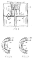
- Figure 2 is a section taken substantially along the line 2-2 of Figure 1, showing the partial insertion of the water bottle in the hygienic liquid dispensing system of Figure 1;
- Figures 3a and 3b are fragmentary sections taken substantially along line 3-3 of the Figure 2, showing a detachable connection between an adaptor unit of the hygienic liquid dispensing system and a separate water bottle cooler;
- Figures 4a, 4b and 4c are enlarged fragmentary side elevation views, partly in section, showing insertion and removal of the feed tube with respect to the hygienic cap in the system of Figure 1; and
- Figure 5 is a fragmentary perspective view showing an alternative adaptor unit having a tapered side wall sitting on top of a water cooler housing.
- While the invention will be described and disclosed in connection with certain preferred embodiments and procedures, it is not intended to limit the invention to those specific embodiments. Rather it is intended to cover all such alternative embodiments and modifications as fall within the spirit and scope of the invention.
- Turning now to the drawings, there is shown in greater detail, a bottled
water cooler 10 including acabinet 20 of the type having an open-toppedcooling reservoir 12 which is disposed to receive the inverted neck of abottle 15 containing water or the like. Typically, thereservoir 12 and its contents are subjected to temperature control by a refrigeration system and/or a heating system (not shown), in the lower portion of thecabinet 20, and water is taken from the reservoir through adrain pipe 22 and afaucet 13 mounted on acabinet front panel 14. In the illustratedcooler 10, thefront panel 14 is recessed within the cabinet periphery so as to set thefaucet 13 back into the cabinet and thus prevent inadvertent contact. - In keeping with the invention, a
mounting adapter 25 is disposed on the upper portion of thewater cooler cabinet 20. To properly support the inverted water bottle, themounting adapter 25 is provided with anannular ring 24 on its upper portion 26 and in order to properly receive and guide the invertedwater bottle 15, themounting adapter 25 is provided with atapered entry portion 27 extending downwardly and inwardly from theannular ring 24 on the upper portion 26 of themounting adapter 25. Theentry portion 27 is formed with alower end 29 having a length greater than the container neck 51, so that substantially all of the weight of the inverted water bottle is supported by theannular ring 24 of themounting adapter 25 rather than by the water bottle neck. In the illustration of FIG. 1, themounting adapter 25 is provided with downwardly extendingside walls 17 and also includes internalstiffening ribs 28 interconnecting theside walls 17, the raised upper portion 26 and thetapered entry portion 27 so as to support theannular ring 24. - As more particularly depicted in FIG. 2, in the preferred embodiment, an
annular diaphragm element 41 coupled to thelower end 29 of theentry portion 27 of themounting adapter 25 sealingly closes the upper portion of thereservoir 12 and supports anupstanding feed tube 45 whose operation is described in greater detail below. - In order that the hygienic liquid dispensing system may be retrofitted to existing water coolers, the diaphragm/feed tube configuration described above carries a flexible
peripheral member 43 for sealingly engaging and closing the open end of thereservoir 12. To facilitate the retrofitting between the mounting adapter and an existing water cooler having the diaphragm/feed tube connection, a quick disconnect means is provided having bayonet-type tab fittings 33 on the diaphragm andcomplementary lugs 34 on thelower end 29 of theentry portion 27 of themounting adapter 25. As shown in greater detail in FIGS. 3a and 3b, one or more of the bayonet-type tab fittings 33 may be provided with centeringdetentlike dimples 35 for engagement withcomplementary recesses 36 formed in the upper surface of thelugs 34 to insure proper engagement of the quick disconnect means. It will be understood, of course, that other suitable attachment means may be provided, if desired. - Pursuant to another feature of the preferred embodiment, and as depicted in Figs. 1 and 2, an
air filter 30 is provided with afilter element 37, having a filter medium removably fitted on the housing 38 of thefilter 30. Aconduit 39 is connected to the filter housing 38 and passes via agrommet 47, through thediaphragm element 41, so that air cannot enter the reservoir except by passing through the filter medium. A more detailed description of thefilter 30 can be found in U.S. Patent No. 4,834,267, issued May 30, 1989 to Schroer et al. and is hereby incorporated by reference. It will also be appreciated with reference to Figure 1, that thefilter 30 may be conveniently located under the raised upper portion 26 of themounting adapter 25. - A
hygienic cap 50 for a liquid dispensing system is shown in Figs. 4a,4b and 4c. As is conventional with water bottles, a neck portion 51 defines a discharge opening through which liquid may dispense. In order to seal liquid within the bottle,hygienic cap 50 is provided with alid portion 53 adapted to overlie and sealingly close the discharge opening defined by the neck 51. Additionally, anannular skirt portion 55 of thecap 50 extends axially away from the periphery of thelid portion 53 and is adapted to surround a portion of the neck 51 so as to sealingly retain contact with the neck portion 51 of the water bottle. As will become more apparent below, thehygienic cap 50 is provided with an axially inwardly extendingrecess 60 formed integrally with or otherwise connected to thelid portion 53. The axially inwardly extendingrecess 60 includes a firstannular sleeve portion 62 which is located generally centrally in thelid portion 53 and is preferably integrally connected thereto. - In keeping with the present invention, a second
annular plug portion 70 is connected to the inner end of the firstannular sleeve portion 62 and extends axially inwardly therefrom. As shown in the illustrated embodiment, the secondannular plug portion 70 is provided with a closedinner end 71 to fully seal liquid within the inverted water bottle. - In keeping with another important aspect of the invention, the second
annular plug portion 70 is preferably integral with the firstannular sleeve portion 62 and is connected thereto through a frangible connection 75 in order to allow theplug portion 70 to be axially separated from thesleeve portion 62 upon the forceable insertion of afeed tube 45 into the inwardly extendingrecess 60 to facilitate the discharge of liquid from the inverted water bottle. The frangible connection 75 includes an area of the recess which has reduced wall thickness at the inner end of thesleeve 62 where theplug portion 70 is connected thereto. This single piece construction not only reduces assembly time but also avoids separation and loss of the plug portion. To this end, in the preferred embodiment, thecap 50 is formed in a single piece. However, it will be appreciated that a two-piece construction may sometimes be advantageous. In this regard, the multiple pieces may thereafter be assembled in a one-piece configuration either by spin welding, sonic welding, chemical bonding or the like. - In order to temporarily secure the
plug 70 on thefeed tube 45 when the feed tube is inserted in therecess 60, theplug portion 70 is formed with aninternal gripping rib 72. In a complementary way, so that thefeed tube 45 may retain theplug portion 70 upon insertion of the feed tube into the inwardly extendingrecess 60,feed tube 45 is provided with anannular groove 42 formed in its outside surface. In order to facilitate proper insertion of thefeed tube 45 inrecess 60, and proper mating engagement between thegripping rib 72 of theplug portion 70 and theannular groove 42 offeed tube 45,feed tube 45 may be provided with anupper portion 44 of reduced diameter and a taperedannular ramp portion 63 adjacent theannular groove 42 for guiding theannular gripping rib 72 into theannular groove 42. - Upon further insertion of the feed tube into the
recess 60, the frangible connection 75 is broken, thereby allowing the extension of thefeed tube 45 into the neck of the inverted water bottle. In a conventional manner,feed tube 45 is formed with aninternal bore 46 and at least oneradial inlet 48 communicating therewith to allow the dispensing of liquid from the interior of the inverted water bottle to thereservoir 12 as more fully described in the above mentioned U.S. Patent No. 4,699,188 to Baker et al. As is apparent and in order to allow fluid flow, theinlet 48 is spaced from the end of thefeed tube 45 by a distance that is greater than the internal depth of theplug 70. - As shown in Fig. 4b, the exterior surface of the
feed tube 45 is dimensioned with respect to the interior of the firstannular sleeve portion 62 so that a sealing engagement is effected upon insertion of thefeed tube 45 into therecess 60 and the inverted water bottle. - The hygienic liquid dispensing system is provided with means for resealing the inverted water bottle upon removal of the water bottle from the cooler or, conversely, upon removal of the feed tube from the
hygienic cap 50. Upon removal offeed tube 45 from the invertedwater bottle 15,annular groove 42 retains theannular plug portion 70 ofhygienic cap 50 until the plug portion is fully drawn into the axially inwardly extendingrecess 60 oflid portion 53. In the preferred embodiment, theplug portion 70 is formed with an outside annular surface dimensioned to sealingly fit within thesleeve portion 62 when thefeed tube 45 is withdrawn from therecess 60. For this purpose, theplug 70 is preferably formed with a tapered lead-insection 69 adjacent the frangible connection 75 for guiding theplug 70 into thesleeve 62 when thefeed tube 45 is withdrawn from therecess 60. Adjacent its closedend 71, theplug portion 70 is also preferably provided with anannular flange 73 in order to prevent theplug portion 70 from being removed from thehygienic cap 60. In the preferred embodiment, the externalannular flange 73 is dimensioned to seat on the inner end of thesleeve 62 when theplug 70 is drawn into the sleeve. Additionally, in order to sealingly engage theplug portion 70 with the firstannular sleeve portion 62 of the hygienic cap,plug portion 70 is provided with an externalannular recess 77 which sealingly cooperates with a radially inwardly projectingbead 76 ofsleeve portion 62. Moreover, this external annular groove/internally projecting bead combination provides a gripping means that will allow thefeed tube 45 to mate with and retain theplug portion 70 prior to the plug portion becoming slideably disengaged with respect to thesleeve portion 62. - In the preferred embodiment, a
hygienic cap 50 is also provided with a line ofweakness 80 on theskirt 55 extending toward thelid portion 53 and apull tab 85 extending axially from the skirt.Pull tab 85 is provided to facilitate manually tearing theskirt 55 along the line ofweakness 80 when thecap 50 is removed from the container. Additionally, the cap is formed to receive aprotective seal 84 covering therecess 60 to prevent contaminants from entering therein. Theprotective seal 84 also serves to indicate whether the cap has been tampered with prior to insertion of thefeed tube 45 into therecess 60. - An alternate embodiment of the invention is illustrated in FIG. 5 wherein the mounting adapter 25a is designed to be positioned on top of an existing water cooler 10a having a flat upper surface. The above described hygienic water bottle system having the hygienic cap, feed tube and mounting diaphragm is housed within the cooler 10a, but is not shown here.
Claims (20)
Priority Applications (1)
| Application Number | Priority Date | Filing Date | Title |
|---|---|---|---|
| EP94109285A EP0641713B1 (en) | 1988-10-14 | 1989-10-06 | Dispensing cap for liquid container |
Applications Claiming Priority (3)
| Application Number | Priority Date | Filing Date | Title |
|---|---|---|---|
| US25762788A | 1988-10-14 | 1988-10-14 | |
| PCT/US1989/004465 WO1990003919A1 (en) | 1988-10-14 | 1989-10-06 | Liquid container support and hygienic liquid dispensing system |
| US257627 | 1999-02-25 |
Related Child Applications (2)
| Application Number | Title | Priority Date | Filing Date |
|---|---|---|---|
| EP94109285A Division EP0641713B1 (en) | 1988-10-14 | 1989-10-06 | Dispensing cap for liquid container |
| EP94109285.0 Division-Into | 1994-06-16 |
Publications (4)
| Publication Number | Publication Date |
|---|---|
| EP0438451A1 EP0438451A1 (en) | 1991-07-31 |
| EP0438451A4 EP0438451A4 (en) | 1992-11-19 |
| EP0438451B1 true EP0438451B1 (en) | 1995-01-11 |
| EP0438451B2 EP0438451B2 (en) | 2002-10-16 |
Family
ID=22977060
Family Applications (2)
| Application Number | Title | Priority Date | Filing Date |
|---|---|---|---|
| EP94109285A Expired - Lifetime EP0641713B1 (en) | 1988-10-14 | 1989-10-06 | Dispensing cap for liquid container |
| EP89911311A Expired - Lifetime EP0438451B2 (en) | 1988-10-14 | 1989-10-06 | Liquid container support and hygienic liquid dispensing system |
Family Applications Before (1)
| Application Number | Title | Priority Date | Filing Date |
|---|---|---|---|
| EP94109285A Expired - Lifetime EP0641713B1 (en) | 1988-10-14 | 1989-10-06 | Dispensing cap for liquid container |
Country Status (18)
| Country | Link |
|---|---|
| US (1) | US5121778A (en) |
| EP (2) | EP0641713B1 (en) |
| JP (1) | JPH0662195B2 (en) |
| KR (1) | KR960011713B1 (en) |
| AR (1) | AR245922A1 (en) |
| AT (2) | ATE153618T1 (en) |
| AU (1) | AU617015B2 (en) |
| BR (1) | BR8907712A (en) |
| CA (1) | CA1338210C (en) |
| DE (2) | DE68928086T2 (en) |
| DK (1) | DK145590A (en) |
| ES (1) | ES2016533A6 (en) |
| FI (1) | FI89780C (en) |
| GR (1) | GR1001176B (en) |
| IL (1) | IL92114A (en) |
| MX (1) | MX172394B (en) |
| PT (1) | PT91978B (en) |
| WO (1) | WO1990003919A1 (en) |
Cited By (1)
| Publication number | Priority date | Publication date | Assignee | Title |
|---|---|---|---|---|
| EP1032537B1 (en) * | 1997-11-19 | 2002-08-28 | Ecolab GmbH & CO. OHG | Device for metering a pasty product |
Families Citing this family (94)
| Publication number | Priority date | Publication date | Assignee | Title |
|---|---|---|---|---|
| US5512228A (en) * | 1991-03-05 | 1996-04-30 | Portola Packaging, Inc. | Unitary tamper-evident fitment and closure assembly |
| US5348182A (en) * | 1991-03-05 | 1994-09-20 | Portola Packaging, Inc. | Means for attaching fitment and method of applying fitment |
| US5249695A (en) * | 1991-03-05 | 1993-10-05 | Portola Packaging, Inc. | Spout fitment closure plug |
| US5348183A (en) * | 1991-03-05 | 1994-09-20 | Portola Packaging, Inc. | Tamper-evident, initially unitary, fitment and closure |
| US5370276A (en) * | 1991-04-22 | 1994-12-06 | Ebtech Inc. | Bottled water station with removable reservoir |
| US5413152C1 (en) * | 1991-10-07 | 2001-11-13 | Oasis Corp | Bottle cap and valve assembly for a bottled water station |
| US5232125A (en) * | 1991-10-08 | 1993-08-03 | Portola Packaging, Inc. | Non-spill bottle cap used with water dispensers |
| US5370270A (en) * | 1991-10-08 | 1994-12-06 | Portola Packaging, Inc. | Non-spill bottle cap used with water dispensers |
| US5213597A (en) * | 1992-01-03 | 1993-05-25 | Campbell Gary J | Filtration system for bottled water dispenser with check valve |
| DE4321490A1 (en) * | 1992-06-23 | 1994-01-05 | Orbital Eng Australia | Reservoir for storing liquids |
| GB9215275D0 (en) * | 1992-07-17 | 1992-09-02 | Ebac Ltd | Liquid dispensers |
| GB9215276D0 (en) * | 1992-07-17 | 1992-09-02 | Ebac Ltd | Liquid dispensers |
| US5439145A (en) * | 1992-07-17 | 1995-08-08 | Ebac Limited | Apparatus for dispensing liquid from an inverted container |
| DE9210547U1 (en) * | 1992-08-06 | 1992-11-19 | Georg Hefter GmbH, 8210 Prien | Automatic coupling device |
| US5259534A (en) * | 1992-08-28 | 1993-11-09 | National Packaging | Container cap with removable insert |
| DE9212623U1 (en) * | 1992-09-18 | 1993-08-05 | Alfred Bolz Gmbh & Co Kg, 88239 Wangen | Safety filling and emptying valve for liquid, pasty and powdery media |
| US5392939A (en) * | 1992-10-01 | 1995-02-28 | Hidding; Walter E. | Valved bottle cap |
| US5868281A (en) * | 1995-05-15 | 1999-02-09 | Portola Packaging, Inc. | Non-spill bottle cap |
| DE59401339D1 (en) * | 1993-02-12 | 1997-01-30 | Klaus Waechter | DISPENSER FOR DRINKABLE LIQUIDS |
| GB9305262D0 (en) * | 1993-03-15 | 1993-05-05 | Hibbert John C | Closure for fluid containers |
| US5807359A (en) | 1993-06-08 | 1998-09-15 | Bemis Manufacturing Company | Medical suction system |
| US5493873A (en) * | 1993-10-20 | 1996-02-27 | Elkay Manufacturing Company | Liquid dispensing device |
| US5415210A (en) * | 1994-01-13 | 1995-05-16 | Hannah; Garnet | Funnel for attachment to one end of a cylindrical drum |
| US5464127A (en) * | 1994-02-28 | 1995-11-07 | Ebtech, Inc. | Sealed actuator probe assembly for a bottled water station |
| US5402836A (en) * | 1994-03-23 | 1995-04-04 | Hasper; Pat K. | Valve assembly for a bottle used in a liquid dispensing apparatus |
| US5533651A (en) * | 1994-12-12 | 1996-07-09 | Eddy; John W. | Universal adapter for liquid dispensers |
| US6358232B1 (en) | 1994-12-29 | 2002-03-19 | Bemis Manufacturing Company | Method and apparatus for removing and disposing of body fluids |
| US5688255A (en) * | 1994-12-29 | 1997-11-18 | Bemis Manufacturing Company | Method and apparatus for removing and disposing of body fluids |
| US5683371A (en) * | 1994-12-29 | 1997-11-04 | Bemis Manufacturing Company | Suction canister apparatus and method |
| US5620428A (en) * | 1994-12-29 | 1997-04-15 | Bemis Manufacturing Company | Suction canister apparatus and method |
| US6244311B1 (en) | 1994-12-29 | 2001-06-12 | Bemis Manufacturing Company | Method and apparatus for removing and disposing of body fluids |
| US5556005A (en) * | 1995-01-09 | 1996-09-17 | Sprintvest Corporation Nv | Collapsible soap dispenser |
| US5577638A (en) * | 1995-02-21 | 1996-11-26 | Takagawa; Nobuyuki | Bottom pouring pot |
| FR2732003B1 (en) * | 1995-03-20 | 1997-06-06 | Mistral Distribution | FOUNTAIN BEVERAGE DISTRIBUTOR |
| US5676278A (en) * | 1995-04-28 | 1997-10-14 | Elkay Manufacturing Company | Water dispensing feed tube with improved flow |
| US5611459A (en) * | 1995-07-12 | 1997-03-18 | Eaucool Canada Inc. | Method of converting an inverted bottle water dispensing system for use with an automatic bottle refill system |
| US6061681A (en) * | 1997-06-30 | 2000-05-09 | Movo Media, Inc. | On-line dating service for locating and matching people based on user-selected search criteria |
| FR2769004B1 (en) * | 1997-10-01 | 1999-12-10 | Rical Sa | SEALING DEVICE FOR A CONTAINER FOR A WATER FOUNTAIN LIQUID DISPENSER |
| US6006388A (en) * | 1998-04-14 | 1999-12-28 | Young; Cecil Blake | Dispenser for dispensing concentrated liquid soap to industrial cleaning apparatuses |
| US5971220A (en) * | 1998-04-15 | 1999-10-26 | Payne; Ernest F. | Water dispenser apparatus and method |
| US6059146A (en) * | 1998-07-29 | 2000-05-09 | Perrier Group Of America | Liquid delivery system that automatically delivers liquid from a plurality of containers |
| USD419370S (en) * | 1998-10-02 | 2000-01-25 | Oasis Corporation | Cap for a water bottle |
| USD429111S (en) * | 1998-10-02 | 2000-08-08 | Oasis Corporation | Feed tube adapter for a bottled water cooler |
| US6123122A (en) * | 1998-10-20 | 2000-09-26 | Abel Unlimited, Inc. | Hygenic bottle cap and liquid dispensing system |
| US6408904B1 (en) | 1998-10-20 | 2002-06-25 | Abel Unlimited, Inc. | Hygienic bottle cap |
| US6200488B1 (en) | 1998-10-28 | 2001-03-13 | Oxygen8, Inc. | Water bottle cap |
| USD417111S (en) | 1999-02-11 | 1999-11-30 | Chester Labs, Inc. | Hinged dispenser housing |
| US6152330A (en) * | 1999-02-11 | 2000-11-28 | Chester Labs, Inc. | Hinged dispenser housing |
| FR2775259B1 (en) * | 1999-03-11 | 2000-10-13 | Rical Sa | SEALING DEVICE FOR A CONTAINER FOR A WATER FOUNTAIN LIQUID DISPENSER |
| US7014759B2 (en) * | 2000-02-18 | 2006-03-21 | Radford Thomas K | Method and apparatus for water purification |
| US7674248B2 (en) * | 2000-03-28 | 2010-03-09 | Bemis Manufacturing Company | Medical suction apparatus and methods for draining same |
| US7585292B2 (en) * | 2000-03-28 | 2009-09-08 | Bemis Manufacturing Company | Medical suction apparatus and draining of same |
| WO2001072350A1 (en) | 2000-03-28 | 2001-10-04 | Bemis Manufacturing Company | Medical suction apparatus and methods for draining same |
| WO2002055134A2 (en) | 2001-01-12 | 2002-07-18 | Bemis Mfg Co | Method and apparatus for disposing of bodily fluids from a container |
| USD448974S1 (en) | 2001-02-08 | 2001-10-09 | Oasis Corporation | Feed tube adapter for a bottled water cooler |
| EP1365952A4 (en) | 2001-02-08 | 2004-08-11 | Oasis Corp | SUPPLY TUBE ADAPTER FOR BOTTLED WATER COOLER |
| GB2383321B (en) * | 2001-12-21 | 2005-07-27 | Ebac Ltd | Feed tube for use in a liquid delivery system |
| CA2418456C (en) | 2003-02-11 | 2011-11-08 | Crealise Conditionnement Inc. | Water bottle plug and method for manufacturing the said plug |
| US20050081953A1 (en) * | 2003-09-05 | 2005-04-21 | Yui George M. | Cold water tank and parts thereof |
| US20050101922A1 (en) * | 2003-11-07 | 2005-05-12 | Bemis Manufacturing Company | Suction canister and drainage of same |
| US8177083B2 (en) | 2004-04-08 | 2012-05-15 | Tetra Laval Holdings & Finance S.A. | Threadless cap with a nonintegral seal |
| US7581653B2 (en) | 2004-04-08 | 2009-09-01 | Crealise Packaging-Conditionnement Inc. | Cap and closure system for closing a large potable liquid bottle |
| US7278554B2 (en) * | 2004-05-10 | 2007-10-09 | Chester Labs, Inc. | Hinged dispenser housing and adaptor |
| CA2493481A1 (en) * | 2004-12-29 | 2006-06-29 | George Yui | Receptable assembly for bottled water dispenser |
| DE102005013927A1 (en) * | 2005-03-26 | 2006-09-28 | Herzberger Bäckerei GmbH | Drink dispenser with adaptor e.g. for water dispenser, has tap provided at housing with funnel connected to cooling equipment having center concave part which is provided with lateral passage |
| US7669738B1 (en) | 2005-07-07 | 2010-03-02 | Byers Thomas L | Water transfer system for a bottled water dispenser |
| US8109378B2 (en) * | 2005-07-14 | 2012-02-07 | Primo Water Corporation | Bottled water distribution method and bottle return apparatus |
| US7921979B2 (en) * | 2005-07-14 | 2011-04-12 | Primo Water Corporation | Bottled water distribution method and bottle return apparatus |
| USD542495S1 (en) | 2005-09-08 | 2007-05-08 | Primo Water Corporation | Bottle return apparatus |
| USD566920S1 (en) | 2005-09-08 | 2008-04-15 | Primo Water Corporation | Bottle return apparatus |
| US7621425B2 (en) * | 2005-12-20 | 2009-11-24 | Genx Innovations, Llc | Apparatus for controlled initiation of fluid-flow from an inverted container |
| US20070267100A1 (en) * | 2006-05-08 | 2007-11-22 | Spear Gregory N | Bottle Cap and Method of Use With a Liquid Dispensing Apparatus and System |
| US20070278175A1 (en) * | 2006-06-06 | 2007-12-06 | Portola Packaging, Inc. | Closure having inverted frangible valve |
| US20070278176A1 (en) * | 2006-06-06 | 2007-12-06 | Portola Packaging Inc. | Closure having a valve with an arcuate frangible line |
| JP4664870B2 (en) * | 2006-06-30 | 2011-04-06 | 株式会社コスモライフ | Cartridge container for beverage dispenser |
| US8281821B2 (en) * | 2006-08-30 | 2012-10-09 | MTN Products, Inc | Leak stop seal for water cooler |
| US20080054017A1 (en) * | 2006-08-30 | 2008-03-06 | Mtn Products, Inc. | Liquid Dispensing Apparatus and System |
| US7434603B2 (en) * | 2006-08-30 | 2008-10-14 | Mtn Products, Inc. | Bottom load water cooler |
| USD582194S1 (en) | 2007-11-13 | 2008-12-09 | Mtn Products, Inc. | Water cooler |
| USD608129S1 (en) | 2008-03-10 | 2010-01-19 | MTN Products, Inc | Water cooler |
| USD623885S1 (en) | 2009-06-18 | 2010-09-21 | Mtn Products, Inc. | Water cooler |
| USD617132S1 (en) | 2009-09-08 | 2010-06-08 | Mtn Products, Inc. | Water cooler |
| US8356731B2 (en) * | 2009-09-09 | 2013-01-22 | Mtn Products Inc | Energy saving baffle for water cooler |
| USD642849S1 (en) | 2010-04-28 | 2011-08-09 | MTN Products, Inc | Water cooler |
| USD643239S1 (en) | 2010-04-28 | 2011-08-16 | MTN Products, Inc | Water cooler |
| US8899398B2 (en) | 2010-09-17 | 2014-12-02 | Zephyr Fluid Solutions, Llc | Apparatus and method for water bottle return |
| USD677509S1 (en) | 2011-09-23 | 2013-03-12 | MTN Products, Inc | Water cooler |
| USD688079S1 (en) | 2012-02-21 | 2013-08-20 | Chun Yen Wang | Combination water dispenser and beverage brewer |
| BR102013001703B1 (en) * | 2013-01-23 | 2022-04-05 | Hélio Vieira Alves | Set of inventions, which includes processes for manufacturing preforms and plastic bottles to store water, transporting it using a transport lid and handle, and which, being placed inverted on a base support and opening its sigh lid and its faucet cap, serves (the water) straight to the outer container |
| US9656850B2 (en) | 2013-09-12 | 2017-05-23 | Lvd Acquisition, Llc | Device and method for preventing the overflow of a fluid reservoir |
| US9580290B1 (en) * | 2016-02-06 | 2017-02-28 | Kenneth John Gallagher | Counter water bottle dispenser |
| NL2017109B1 (en) | 2016-07-05 | 2018-01-12 | Heineken Supply Chain Bv | Beverage dispensing assembly and beverage container |
| NL2018955B1 (en) | 2017-05-19 | 2018-11-28 | Heineken Supply Chain Bv | Beverage dispensing assembly and beverage container |
| NL2018956B1 (en) | 2017-05-19 | 2018-11-28 | Heineken Supply Chain Bv | Beverage dispensing assembly and beverage container |
Family Cites Families (22)
| Publication number | Priority date | Publication date | Assignee | Title |
|---|---|---|---|---|
| CA631376A (en) * | 1961-11-21 | R. Schultz Wilfred | Combined hot and cold fluid dispensing apparatus | |
| US1325427A (en) * | 1919-12-16 | X w water-cooler | ||
| US497896A (en) * | 1893-05-23 | The morris petxss co | ||
| US1009437A (en) * | 1910-06-09 | 1911-11-21 | Atwood L Boggs | Inverted-bottle water-cooler. |
| US1142210A (en) * | 1912-02-29 | 1915-06-08 | Rayvio Water Company | Liquid-dispensing device. |
| US1976007A (en) * | 1931-11-04 | 1934-10-09 | Alfred F Pillsbury | Water cooler |
| US2811272A (en) * | 1951-12-03 | 1957-10-29 | Lawlor William | Sanitary shields for spring water drinking dispensers |
| US3893599A (en) * | 1972-10-25 | 1975-07-08 | Cornelius Co | Means for dispensing |
| US4239130A (en) * | 1979-04-18 | 1980-12-16 | Altadonna Lawrence J | Oil caddy |
| US4267945A (en) * | 1979-08-06 | 1981-05-19 | Maynard Jr Walter P | Liquid funnel and container piercing blade combination |
| USRE32354E (en) * | 1980-07-21 | 1987-02-17 | Scholle Corporation | Container for holding and dispensing fluid |
| US4445551A (en) * | 1981-11-09 | 1984-05-01 | Bond Curtis J | Quick-disconnect coupling and valve assembly |
| EP0093157B1 (en) * | 1981-11-09 | 1989-05-10 | Liqui-Box Corporation | Coupling and valve assembly for a liquid dispenser |
| US4436125A (en) * | 1982-03-17 | 1984-03-13 | Colder Products Company | Quick connect coupling |
| US4597423A (en) | 1985-03-26 | 1986-07-01 | Chenot Gary D | Device for opening bottled water containers |
| US4699188A (en) * | 1986-01-17 | 1987-10-13 | Baker Henry E | Hygienic liquid dispensing system |
| US4717051A (en) * | 1986-09-02 | 1988-01-05 | Guy Leclerc | Check valve for water dispenser bottle |
| US4846236A (en) * | 1987-07-06 | 1989-07-11 | Deruntz William R | Bottled water dispenser insert |
| US4834267A (en) * | 1987-11-02 | 1989-05-30 | Elkay Manufacturing Company | Bottled water cooler air filter |
| US4779426A (en) * | 1987-12-22 | 1988-10-25 | Les Produits Addico Inc. | Water cooler with one-piece removable well |
| US4991635A (en) * | 1988-09-30 | 1991-02-12 | Liqui-Box Corporation | Decap dispensing system for water cooler bottles |
| US4874023A (en) * | 1988-09-30 | 1989-10-17 | Liqui-Box Corporation | Decap dispensing system for water cooler bottles |
-
1989
- 1989-09-29 CA CA000614950A patent/CA1338210C/en not_active Expired - Lifetime
- 1989-10-06 JP JP1510574A patent/JPH0662195B2/en not_active Expired - Fee Related
- 1989-10-06 EP EP94109285A patent/EP0641713B1/en not_active Expired - Lifetime
- 1989-10-06 AT AT94109285T patent/ATE153618T1/en not_active IP Right Cessation
- 1989-10-06 AU AU44051/89A patent/AU617015B2/en not_active Ceased
- 1989-10-06 EP EP89911311A patent/EP0438451B2/en not_active Expired - Lifetime
- 1989-10-06 KR KR1019900701269A patent/KR960011713B1/en not_active Expired - Fee Related
- 1989-10-06 DE DE68928086T patent/DE68928086T2/en not_active Expired - Fee Related
- 1989-10-06 AT AT89911311T patent/ATE116949T1/en not_active IP Right Cessation
- 1989-10-06 WO PCT/US1989/004465 patent/WO1990003919A1/en not_active Ceased
- 1989-10-06 DE DE68920588T patent/DE68920588T2/en not_active Expired - Fee Related
- 1989-10-06 BR BR898907712A patent/BR8907712A/en not_active IP Right Cessation
- 1989-10-11 MX MX017930A patent/MX172394B/en unknown
- 1989-10-11 AR AR89315142A patent/AR245922A1/en active
- 1989-10-13 ES ES8903459A patent/ES2016533A6/en not_active Expired - Lifetime
- 1989-10-13 GR GR890100655A patent/GR1001176B/en unknown
- 1989-10-13 PT PT91978A patent/PT91978B/en not_active IP Right Cessation
- 1989-10-25 IL IL92114A patent/IL92114A/en not_active IP Right Cessation
-
1990
- 1990-06-14 DK DK145590A patent/DK145590A/en not_active Application Discontinuation
-
1991
- 1991-04-12 FI FI911779A patent/FI89780C/en not_active IP Right Cessation
- 1991-04-12 US US07/684,642 patent/US5121778A/en not_active Expired - Lifetime
Cited By (1)
| Publication number | Priority date | Publication date | Assignee | Title |
|---|---|---|---|---|
| EP1032537B1 (en) * | 1997-11-19 | 2002-08-28 | Ecolab GmbH & CO. OHG | Device for metering a pasty product |
Also Published As
| Publication number | Publication date |
|---|---|
| ATE153618T1 (en) | 1997-06-15 |
| MX172394B (en) | 1993-12-15 |
| AU4405189A (en) | 1990-05-01 |
| DK145590D0 (en) | 1990-06-14 |
| KR900701603A (en) | 1990-12-03 |
| EP0438451A4 (en) | 1992-11-19 |
| EP0641713B1 (en) | 1997-05-28 |
| US5121778A (en) | 1992-06-16 |
| GR1001176B (en) | 1993-06-07 |
| DE68928086D1 (en) | 1997-07-03 |
| FI911779A0 (en) | 1991-04-12 |
| DK145590A (en) | 1990-06-14 |
| WO1990003919A1 (en) | 1990-04-19 |
| AR245922A1 (en) | 1994-03-30 |
| ES2016533A6 (en) | 1990-11-01 |
| PT91978B (en) | 1995-08-09 |
| FI89780B (en) | 1993-08-13 |
| KR960011713B1 (en) | 1996-08-30 |
| ATE116949T1 (en) | 1995-01-15 |
| DE68928086T2 (en) | 1997-11-20 |
| IL92114A0 (en) | 1990-07-12 |
| EP0438451A1 (en) | 1991-07-31 |
| DE68920588T2 (en) | 1995-08-17 |
| DE68920588D1 (en) | 1995-02-23 |
| AU617015B2 (en) | 1991-11-14 |
| PT91978A (en) | 1990-04-30 |
| FI89780C (en) | 1993-11-25 |
| CA1338210C (en) | 1996-04-02 |
| GR890100655A (en) | 1990-11-29 |
| EP0641713A1 (en) | 1995-03-08 |
| JPH03503273A (en) | 1991-07-25 |
| BR8907712A (en) | 1991-07-30 |
| JPH0662195B2 (en) | 1994-08-17 |
| IL92114A (en) | 1993-02-21 |
| EP0438451B2 (en) | 2002-10-16 |
Similar Documents
| Publication | Publication Date | Title |
|---|---|---|
| EP0438451B2 (en) | Liquid container support and hygienic liquid dispensing system | |
| US5222531A (en) | Liquid container support and hygienic liquid dispensing system | |
| US5295519A (en) | Hygienic liquid dispensing system including feed tube or probe for opening and resealing coaxial cap | |
| US5222530A (en) | Hygienic cap and liquid dispensing system | |
| US5289855A (en) | Liquid container support and probe-type hygienic liquid dispensing system | |
| US5295518A (en) | Two-piece hygienic cap with resealable plug and tearable skirt with pull tab | |
| EP0569584B2 (en) | bottled water station | |
| US5647416A (en) | Bottled water dispenser system | |
| CA1291969C (en) | Hygienic liquid dispensing system | |
| US5676278A (en) | Water dispensing feed tube with improved flow | |
| US4144901A (en) | Probe system for containers | |
| US5361942A (en) | Liquid dispensers having removable components | |
| PL197243B1 (en) | Recyclable filter cartridge and pressure vessel | |
| EP1456113B1 (en) | Feed tube for use in a liquid delivery system | |
| CA1338339C (en) | Liquid container support and hygienic liquid dispensing system | |
| CA2171515C (en) | Bottled water dispenser system | |
| US20050224133A1 (en) | Receptacle assembly for bottled water dispenser |
Legal Events
| Date | Code | Title | Description |
|---|---|---|---|
| PUAI | Public reference made under article 153(3) epc to a published international application that has entered the european phase |
Free format text: ORIGINAL CODE: 0009012 |
|
| 17P | Request for examination filed |
Effective date: 19901227 |
|
| AK | Designated contracting states |
Kind code of ref document: A1 Designated state(s): AT BE CH DE FR GB IT LI NL SE |
|
| A4 | Supplementary search report drawn up and despatched |
Effective date: 19920929 |
|
| AK | Designated contracting states |
Kind code of ref document: A4 Designated state(s): AT BE CH DE FR GB IT LI NL SE |
|
| 17Q | First examination report despatched |
Effective date: 19930528 |
|
| GRAA | (expected) grant |
Free format text: ORIGINAL CODE: 0009210 |
|
| AK | Designated contracting states |
Kind code of ref document: B1 Designated state(s): AT BE CH DE FR GB IT LI NL SE |
|
| PG25 | Lapsed in a contracting state [announced via postgrant information from national office to epo] |
Ref country code: IT Free format text: LAPSE BECAUSE OF FAILURE TO SUBMIT A TRANSLATION OF THE DESCRIPTION OR TO PAY THE FEE WITHIN THE PRE;WARNING: LAPSES OF ITALIAN PATENTS WITH EFFECTIVE DATE BEFORE 2007 MAY HAVE OCCURRED AT ANY TIME BEFORE 2007. THE CORRECT EFFECTIVE DATE MAY BE DIFFERENT FROM THE ONE RECORDED.SCRIBED TIME-LIMIT Effective date: 19950111 Ref country code: LI Effective date: 19950111 Ref country code: FR Free format text: LAPSE BECAUSE OF FAILURE TO SUBMIT A TRANSLATION OF THE DESCRIPTION OR TO PAY THE FEE WITHIN THE PRESCRIBED TIME-LIMIT Effective date: 19950111 Ref country code: CH Effective date: 19950111 Ref country code: NL Free format text: LAPSE BECAUSE OF FAILURE TO SUBMIT A TRANSLATION OF THE DESCRIPTION OR TO PAY THE FEE WITHIN THE PRESCRIBED TIME-LIMIT Effective date: 19950111 Ref country code: AT Effective date: 19950111 |
|
| REF | Corresponds to: |
Ref document number: 116949 Country of ref document: AT Date of ref document: 19950115 Kind code of ref document: T |
|
| XX | Miscellaneous (additional remarks) |
Free format text: TEILANMELDUNG 94109285.0 EINGEREICHT AM 06/10/89. |
|
| REF | Corresponds to: |
Ref document number: 68920588 Country of ref document: DE Date of ref document: 19950223 |
|
| PG25 | Lapsed in a contracting state [announced via postgrant information from national office to epo] |
Ref country code: SE Effective date: 19950411 |
|
| REG | Reference to a national code |
Ref country code: CH Ref legal event code: PL |
|
| ET | Fr: translation filed | ||
| PLBI | Opposition filed |
Free format text: ORIGINAL CODE: 0009260 |
|
| 26 | Opposition filed |
Opponent name: EBCO MANUFACTURING COMPANY Effective date: 19951006 |
|
| NLR1 | Nl: opposition has been filed with the epo |
Opponent name: EBCO MANUFACTURING COMPANY |
|
| PLBF | Reply of patent proprietor to notice(s) of opposition |
Free format text: ORIGINAL CODE: EPIDOS OBSO |
|
| PLBF | Reply of patent proprietor to notice(s) of opposition |
Free format text: ORIGINAL CODE: EPIDOS OBSO |
|
| PLAV | Examination of admissibility of opposition |
Free format text: ORIGINAL CODE: EPIDOS OPEX |
|
| PLAV | Examination of admissibility of opposition |
Free format text: ORIGINAL CODE: EPIDOS OPEX |
|
| PLAB | Opposition data, opponent's data or that of the opponent's representative modified |
Free format text: ORIGINAL CODE: 0009299OPPO |
|
| R26 | Opposition filed (corrected) |
Opponent name: OASIS CORPORATION Effective date: 19951006 |
|
| PLAW | Interlocutory decision in opposition |
Free format text: ORIGINAL CODE: EPIDOS IDOP |
|
| NLR1 | Nl: opposition has been filed with the epo |
Opponent name: OASIS CORPORATION |
|
| APAC | Appeal dossier modified |
Free format text: ORIGINAL CODE: EPIDOS NOAPO |
|
| APAE | Appeal reference modified |
Free format text: ORIGINAL CODE: EPIDOS REFNO |
|
| APAC | Appeal dossier modified |
Free format text: ORIGINAL CODE: EPIDOS NOAPO |
|
| APAC | Appeal dossier modified |
Free format text: ORIGINAL CODE: EPIDOS NOAPO |
|
| REG | Reference to a national code |
Ref country code: GB Ref legal event code: IF02 |
|
| PLAW | Interlocutory decision in opposition |
Free format text: ORIGINAL CODE: EPIDOS IDOP |
|
| PUAH | Patent maintained in amended form |
Free format text: ORIGINAL CODE: 0009272 |
|
| STAA | Information on the status of an ep patent application or granted ep patent |
Free format text: STATUS: PATENT MAINTAINED AS AMENDED |
|
| PGFP | Annual fee paid to national office [announced via postgrant information from national office to epo] |
Ref country code: FR Payment date: 20021008 Year of fee payment: 14 |
|
| PGFP | Annual fee paid to national office [announced via postgrant information from national office to epo] |
Ref country code: DE Payment date: 20021011 Year of fee payment: 14 |
|
| 27A | Patent maintained in amended form |
Effective date: 20021016 |
|
| AK | Designated contracting states |
Kind code of ref document: B2 Designated state(s): AT BE CH DE FR GB IT LI NL SE |
|
| XX | Miscellaneous (additional remarks) |
Free format text: TEILANMELDUNG 94109285.0 EINGEREICHT AM 06/10/89. |
|
| PGFP | Annual fee paid to national office [announced via postgrant information from national office to epo] |
Ref country code: NL Payment date: 20021031 Year of fee payment: 14 |
|
| NLR2 | Nl: decision of opposition | ||
| PGFP | Annual fee paid to national office [announced via postgrant information from national office to epo] |
Ref country code: BE Payment date: 20021219 Year of fee payment: 14 |
|
| NLV1 | Nl: lapsed or annulled due to failure to fulfill the requirements of art. 29p and 29m of the patents act | ||
| EN | Fr: translation not filed | ||
| PG25 | Lapsed in a contracting state [announced via postgrant information from national office to epo] |
Ref country code: BE Free format text: LAPSE BECAUSE OF NON-PAYMENT OF DUE FEES Effective date: 20031031 |
|
| PG25 | Lapsed in a contracting state [announced via postgrant information from national office to epo] |
Ref country code: DE Free format text: LAPSE BECAUSE OF NON-PAYMENT OF DUE FEES Effective date: 20040501 |
|
| APAH | Appeal reference modified |
Free format text: ORIGINAL CODE: EPIDOSCREFNO |
|
| PGFP | Annual fee paid to national office [announced via postgrant information from national office to epo] |
Ref country code: GB Payment date: 20071003 Year of fee payment: 19 |
|
| GBPC | Gb: european patent ceased through non-payment of renewal fee |
Effective date: 20081006 |
|
| PG25 | Lapsed in a contracting state [announced via postgrant information from national office to epo] |
Ref country code: GB Free format text: LAPSE BECAUSE OF NON-PAYMENT OF DUE FEES Effective date: 20081006 |