EP0437631B1 - Image forming apparatus - Google Patents
Image forming apparatus Download PDFInfo
- Publication number
- EP0437631B1 EP0437631B1 EP90911328A EP90911328A EP0437631B1 EP 0437631 B1 EP0437631 B1 EP 0437631B1 EP 90911328 A EP90911328 A EP 90911328A EP 90911328 A EP90911328 A EP 90911328A EP 0437631 B1 EP0437631 B1 EP 0437631B1
- Authority
- EP
- European Patent Office
- Prior art keywords
- ink
- ink sheet
- image formation
- sheet
- setting
- Prior art date
- Legal status (The legal status is an assumption and is not a legal conclusion. Google has not performed a legal analysis and makes no representation as to the accuracy of the status listed.)
- Expired - Lifetime
Links
- 230000015572 biosynthetic process Effects 0.000 claims abstract description 231
- 238000011069 regeneration method Methods 0.000 claims abstract description 71
- 230000008929 regeneration Effects 0.000 claims abstract description 69
- 230000001172 regenerating effect Effects 0.000 claims abstract description 19
- 238000011144 upstream manufacturing Methods 0.000 claims abstract description 11
- 230000002441 reversible effect Effects 0.000 claims description 10
- 230000007246 mechanism Effects 0.000 abstract description 33
- 239000000976 ink Substances 0.000 description 478
- 230000032258 transport Effects 0.000 description 31
- 238000007639 printing Methods 0.000 description 8
- 238000000034 method Methods 0.000 description 7
- 239000000463 material Substances 0.000 description 6
- 230000008901 benefit Effects 0.000 description 4
- 238000010438 heat treatment Methods 0.000 description 4
- 230000008569 process Effects 0.000 description 4
- 238000000151 deposition Methods 0.000 description 3
- 238000010276 construction Methods 0.000 description 2
- 230000007547 defect Effects 0.000 description 2
- 230000008021 deposition Effects 0.000 description 2
- 238000001514 detection method Methods 0.000 description 2
- 238000005516 engineering process Methods 0.000 description 2
- 230000006872 improvement Effects 0.000 description 2
- 230000008018 melting Effects 0.000 description 2
- 238000002844 melting Methods 0.000 description 2
- 238000012544 monitoring process Methods 0.000 description 2
- 238000000926 separation method Methods 0.000 description 2
- 230000000153 supplemental effect Effects 0.000 description 2
- 239000004952 Polyamide Substances 0.000 description 1
- 239000004642 Polyimide Substances 0.000 description 1
- UCKMPCXJQFINFW-UHFFFAOYSA-N Sulphide Chemical compound [S-2] UCKMPCXJQFINFW-UHFFFAOYSA-N 0.000 description 1
- 230000002411 adverse Effects 0.000 description 1
- XAGFODPZIPBFFR-UHFFFAOYSA-N aluminium Chemical compound [Al] XAGFODPZIPBFFR-UHFFFAOYSA-N 0.000 description 1
- 229910052782 aluminium Inorganic materials 0.000 description 1
- 239000006229 carbon black Substances 0.000 description 1
- 230000001112 coagulating effect Effects 0.000 description 1
- 239000004020 conductor Substances 0.000 description 1
- 230000001276 controlling effect Effects 0.000 description 1
- 230000000994 depressogenic effect Effects 0.000 description 1
- 230000006866 deterioration Effects 0.000 description 1
- 230000000694 effects Effects 0.000 description 1
- 238000007667 floating Methods 0.000 description 1
- 229910052739 hydrogen Inorganic materials 0.000 description 1
- 238000009434 installation Methods 0.000 description 1
- 230000007774 longterm Effects 0.000 description 1
- 239000000696 magnetic material Substances 0.000 description 1
- 230000005389 magnetism Effects 0.000 description 1
- 239000000155 melt Substances 0.000 description 1
- 230000003287 optical effect Effects 0.000 description 1
- 229920002647 polyamide Polymers 0.000 description 1
- 229920000139 polyethylene terephthalate Polymers 0.000 description 1
- 229920001721 polyimide Polymers 0.000 description 1
- 229920006254 polymer film Polymers 0.000 description 1
- 229920006389 polyphenyl polymer Polymers 0.000 description 1
- 239000000843 powder Substances 0.000 description 1
- 230000003449 preventive effect Effects 0.000 description 1
- 230000009467 reduction Effects 0.000 description 1
- 230000001105 regulatory effect Effects 0.000 description 1
- 238000005096 rolling process Methods 0.000 description 1
- 238000007665 sagging Methods 0.000 description 1
- 125000006850 spacer group Chemical group 0.000 description 1
- 238000007651 thermal printing Methods 0.000 description 1
- 230000001960 triggered effect Effects 0.000 description 1
Images














Classifications
-
- B—PERFORMING OPERATIONS; TRANSPORTING
- B41—PRINTING; LINING MACHINES; TYPEWRITERS; STAMPS
- B41J—TYPEWRITERS; SELECTIVE PRINTING MECHANISMS, i.e. MECHANISMS PRINTING OTHERWISE THAN FROM A FORME; CORRECTION OF TYPOGRAPHICAL ERRORS
- B41J31/00—Ink ribbons; Renovating or testing ink ribbons
- B41J31/14—Renovating or testing ink ribbons
- B41J31/16—Renovating or testing ink ribbons while fitted in the machine using the ink ribbons
Definitions
- This invention chiefly concerns a thermal-transfer-type image formation device which has an ink sheet regeneration mechanism.
- it concerns an image formation device that performs ink sheet regeneration using powdered ink.
- the thermal transfer image formation device is a very compact and highly reliable device which has been used for some thermal transfer image formation devices, such as facsimile machines.
- the reason that it has not been disseminated to an even greater extent is because its high operating cost has been a major hindrance.
- the cause of the high operating cost is that the ink sheet can only be used one time. It has been widely demanded that the ink sheet be usable for a number of times. With that objective, a number of methods have been devised to regenerate the ink sheet.
- an ink layer direct regeneration system which melts ink using a thermal source and supplies the melted ink to the ink sheet to regenerate the ink layer, has been proposed as a method and a device for regenerating an ink sheet ink layer with sections that have been used for thermal transfer.
- Regeneration methods that use powdered ink have been announced in patents such as USP-4467332.
- image formation devices are disclosed in Japanese patent application numbers 63-110493, 63-111081 and 63-36114, which all use conductive powdered ink.
- the objectives of this invention are to make possible effective and positive ink sheet regeneration and to offer an image formation device that is highly reliable at low operating costs.
- This invention also offers an image formation device in which the regeneration means is positioned upstream of the image formation means relative to the direction of ink sheet travel.
- this invention also offers an image formation device in which the ink sheet regeneration means is positioned downstream of the image formation means relative to the direction of ink sheet travel.
- this invention offers an image formation device in which the ink sheet is an endless ink sheet.
- a variety of operating sequences can be executed with this image formation device. These operating sequences will continue to regenerate the ink sheet when the power is turned on, when there is a reset, at the beginning of image formation, and at the end of image formation or when the power is turned off. These includes operations that will transport the ink sheet a specified distance only or transport the ink sheet an appropriate distance while the ink on the ink sheet is setting.
- Figure 1 is a drawing of one embodiment of the image formation device of this invention.
- the ink sheet regeneration mechanism is positioned upstream of the image formation mechanism.
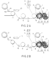
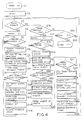
- FIGS 2A through 2D are drawings that describe the embodiment of Figure 1.
- Figure 3 is a drawing of another embodiment of the image formation device of this invention.
- the ink sheet regeneration mechanism which is appropriate for a serial printer, is positioned upstream of the image formation mechanism.
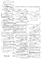
- Figure 4 is a flow chart of one example of an operating sequence that applies to the embodiment in Figure 1.
- Figure 5 is a graph that shows the relationship between the ink that remains unset and the density of printing.
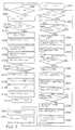
- Figure 6 is a flow chart of another example of an operating sequence that applies to the embodiment in Figure 1.
- Figure 7 is a flow chart of yet another example of an operating sequence that applies to the embodiment in Figure 1.
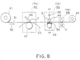
- Figure 8 is a drawing of an embodiment in which the ink sheet regeneration mechanism is positioned downstream of the image formation mechanism.
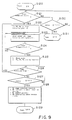
- Figure 9 is a flow chart showing one example of an operating sequence that applies to the embodiment in Figure 8.
- Figure 10 is a flow chart of another example of an operating sequence that applies to the embodiment in Figure 8.
- Figure 11 is a flow chart of a variation of the example of the operating sequence in Figure 9.
- Figure 12 is a flow chart of another variation of the example of the operating sequence in Figure 9.
- Figure 13 is a flow chart of a variation of the operating sequence in Figure 10.
- Figure 14 is a flow chart of another variation of the operating sequence in Figure 10.
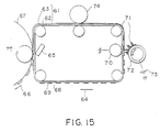
- Figure 15 is a drawing of the general configuration of one embodiment of the image formation device of this invention in which the ink sheet is an endless ink sheet.
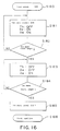
- Figure 16 is a flow chart of one example of operating sequence that applies to the embodiment of Figure 15.
- FIGS 17A through 17D are drawings that shows the condition of the device in various processes during the execution of the operating sequences in Figure 16.
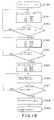
- Figure 18 is a flow chart of another example of the operating sequence that applies to the embodiment in Figure 15.
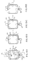
- Figures 19A through 19D are drawings that show the condition of the device at each step during the execution of the operating sequence in Figure 18.
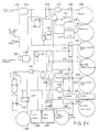
- Figure 20 and Figure 21 are drawings that show the resetting of the control circuit for implementing the operating sequence in Figure 4 and show the circuit conditions when images are formed in Figure 4, respectively.
- Figure 22 and Figure 23 are drawings that show the resetting of the control circuit for executing the operating sequence in Figure 6 and show the circuit conditions when images are formed in Figure 6, respectively.
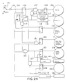
- Figure 24 is a drawing that shows the circuit condition when the control circuit power supply switch for executing the operating sequence in Figure 7 is turned off.
- Figure 25 and Figure 26 are drawings that show circuit conditions of the control circuit for executing the operating sequence in Figure 10 and show the circuit condition when the power supply switch is turned on in Figure 10, respectively.
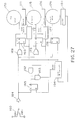
- Figure 27 is a drawing that shows the circuit conditions when the control circuit power supply switch is turned off in order to execute the operating sequence in Figure 10.
- Figure 28 is a drawing that shows the circuit conditions of the control circuit in order to execute the operating sequence in Figure 11 to form images.
- Figure 29 is a drawing that shows the circuit conditions when the control circuit is at standby and when the power supply switch is turned off in order to execute the operating sequence in Figure 12.
- Figure 30 is a drawing that shows the circuit conditions of the control circuit in order to implement the operating sequence in Figure 13 to form images.
- Figure 31 is a drawing that shows the circuit conditions when the control circuit is at standby and when the power supply switch is turned off in order to implement the operating sequence in Figure 14.
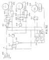
- Figure 32 is a schematic of the control circuit for executing the operating sequences in Figures 16 and 18.
- Figure 33 is a schematic of the control circuit for executing the operating sequence in Figure 18.
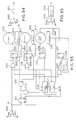
- Figure 34 is an example of a variation of a schematic that can be applied to the circuits in Figures 32 and 33.
- Figure 35 is an example of another variation of a schematic that can be applied to the circuits in Figures 32 and 33.
- Figure 1 is a drawing of one embodiment of the image formation device of this invention.
- This embodiment is an example that uses powdered ink for ink sheet regeneration. It is an example of a line printer in which there is a line printer thermal head and a broad ink sheet.
- Reference number 1 is a feed roller for feeding the ink sheet.
- Reference number 2 is a take-up roller for rolling up the ink sheet.
- ink sheet 3 is wound around feed roller 1. While being unwound from feed roller 1 in the direction of arrow number 4, the ink sheet is regenerated and image formation takes place. The ink sheet then winds around the take-up roller 2.
- Reference number 5 shows the powdered ink feed mechanism. Whether or not the powdered ink is attracted and deposited on ink sheet 3 can be controlled by means of the voltage placed on back-side electrode roller 6. As control voltage, voltage Vb is applied to back-side electrode roller 6 from power supply 8. Whether or not powdered ink is deposited in the specified amount on ink sheet 3 and whether or not back-side electrode roller 6 is grounded, which does not allow the powdered ink to be deposited on the ink sheet, is controlled by changing the switch position of switching element 7. (In this example, grounding means having the same electrical potential as the machine casing. It does not necessarily have to be an absolute ground. However, a connection to absolute ground is desirable.)
- Reference number 9 is a heat roller for setting the powdered ink on the ink sheet.
- heat roller 9 when hot, heat roller 9 is placed in contact with the ink sheet.
- the ink is set on the ink sheet as a result of the heating and melting of the powdered ink.
- Reference number 10 is a line printer thermal head.
- ink sheet 3 and recording paper 12 are placed in contact with each other between platen 11, which is made of a rubber roller, and thermal head 10.
- Recording paper 12 is moved simultaneously with ink sheet 3 and at the same speed in the direction of arrow 13.
- the ink on the ink sheet is thermally melted and transferred to the recording paper between platen roller 11 and thermal head 10 by means of the application of constant pressure, and an image is formed.
- guide rollers 14, 15 and 16 have been provided in the image formation device in Figure 1 to control the travel of the ink sheet.
- Guide rollers 14 and 15 in particular control the contact and non-contact between heat roller 9 and ink sheet 3.
- the ink sheet and the heat roller make mutual contact, setting the powdered ink on the surface of the ink sheet.
- guide rollers 14 and 15 move downward, the ink sheet and heat roller no longer make contact with each other.
- heat is not applied to the ink sheet when it is not needed to set the powdered ink, and this limits to a minimum the thermal deterioration of the ink sheet.
- Guide roller 16 operates as a control on the separation angle between the ink sheet and transfer paper after they pass by it. At the same time, it also operates as the guide roller that prevents the thermal head and ink sheet from coming into contact between the thermal head and the platen during non-contact times. The ink sheet durability increases as a result of this operation, because unnecessary mechanical tension is not applied to the ink sheet.
- Powdered ink supply mechanism 5 is composed of powdered ink container 18, which holds powdered ink 17. Powdered ink 17 has electrical conductivity and magnetic properties. Powdered ink supply mechanism 5 is also composed of agitator 19, which agitates powdered ink 17 in container 18 to prevent it from coagulating, and transports the powdered ink to conductive sleeve 20. Ink supply mechanism 5 is also composed of conductive sleeve 20, which is grounded and rotates in the direction of arrow 23. It deposits the powdered ink on the surface of the ink sheet while transporting the ink, and it supplies an electrical charge to the powdered ink.
- Ink supply mechanism 5 is also composed of magnet 21, which emits a multipolar magnetism, is located within conductive sleeve 20 and causes the surface of conductive sleeve 20 to generate a magnetic attraction that causes the powdered ink to adhere to the surface of conductive sleeve 20.
- Ink supply mechanism 5 is also composed of doctor blade 22, which regulates the amount of powdered ink that is deposited on conductive sleeve 20.
- the gap between back-side electrode roller 6 and conductive sleeve 20 is tightly controlled by runners or spacers.
- the main component of the powdered ink is a material such as a low melting point wax.
- a material that contains an appropriate amount of a strong magnetic material such as the conductive material of carbon black and magnetites.
- any of the powdered inks that show strong magnetic properties, melt by heat, demonstrate conductivity and can be transported by the conductive sleeve can be used.
- a diameter should be selected which is based on the minimum amount of the powdered ink that satisfies the required concentration for the images being deposited on the surface of the ink sheet in one even layer.
- a grain size of 10 micrometers is a standard value. However, grain sizes within a range of 5 micrometers to 20 micrometers are acceptable.
- Ink sheet 3 is made of a base film that has electrically insulating properties.
- the ink has electrically conductive properties.
- Ink sheet 3 does not have to be an ink sheet base that has had ink applied to it in advance.
- An ink sheet base that has had no ink applied to it in advance is acceptable. This is because an ink layer can be formed on this base while image formation is taking place.
- An electrode may be formed on the back surface of the ink sheet. If such an electrode is formed, the amount of voltage Vb that must be applied to back-side electrode roller 6 when the ink sheet is being regenerated can be reduced.
- the back-surface electrode does not have to be electrically connected throughout the entire back surface of the ink sheet. Island-shaped electrode groups that are electrically isolated are acceptable. Electrically isolated electrodes are desirable because they have the role of preventing large current flows when there is an electrical leak.
- ink will not be deposited on ink sheet 3 areas where ink already exists. Thus, only those areas of ink sheet 3 where the ink has been used will be regenerated, with a constant amount of ink.
- a regenerated ink sheet at this stage can be considered to be in an unstable condition because the powdered ink is such that it will be deposited on the ink sheet by means of electrostatic force only, because the depositing force is itself weak, and because the charge within the powdered ink will dissipate over time and the electrostatic force will be lost.
- the powdered ink is set positively to the ink sheet. Adding a step that uses heat roller 9 to melt the powdered ink and increase the force that attracts the ink to the ink sheet will allow stable ink sheet regeneration to take place.
- the surface of the ink layer does not have to be smooth and flat. Because pressure will be applied to this layer in later image formation steps, it is acceptable for the surface of the ink layer to be granular or disjointed. In some cases, edges of outlines of characters coated with ink are sharp by the disjointedness of the ink layer and better image quality can be created.
- Feed roller 1 and take-up roller 2 and ink sheet 3 are housed in an ink sheet cartridge (not shown) that is a single unit.
- the ink sheet take-up section and the ink sheet feed section of the cartridge have the same shape. Once the ink sheet is [completely] wound onto the take-up section, the cartridge can be removed and re-installed in the opposite direction. Now the take-up section will function as the feed section.
- the roller section has been provided with a tautness mechanism that maintains the tautness of the ink sheet using a stopper that operates when the cartridge is removed from the image formation device.
- the body of the image formation device is constructed so that it can be divided up into an upper and lower section.
- the upper section is constructed so that the parts of the upper and lower sections that are connected form a fulcrum, and the upper section can be moved upward to remove the ink sheet cartridge.
- the upper section is of a two-unit construction: a casing and a movable upper frame.
- a constant torque is continuously placed on feed roller 1 so that an appropriate amount of tension is on ink sheet 3. This prevents the wrinkling and sagging of ink sheet 3.
- the main motive force of the ink sheet is the that force put on platen roller 11.
- the supplemental motive force in the motive force applied to ink sheet take-up roller 2.
- the main motive force is used when moving the ink sheet to form images and the supplemental motive force is used when moving the ink sheet when the thermal head moves away from platen roller 11.
- the image formation device is in the non-operating condition, which is similar to the standby condition, when the power has not been turned on.
- the back-side electrode roller In the non-operating condition, the back-side electrode roller is electrically in a floating condition.
- the conductive sleeve is not rotating and is the same electrical potential as the main casing.
- Guide rollers 14 and 15 are in a downward position, and heat roller 9 and the ink sheet are maintained in a non-contact condition.
- Thermal head 10 is also not in contact with the ink sheet.
- the standby condition is the condition in which the image formation device is waiting for a command to start forming images. This is indicated in Figure 2A. That is, the back-side electrode roller is grounded, the conductive sleeve is not rotating, guide rollers 14 and 15 have moved downward, and heat roller 9 and ink sheet 3 are not in contact with each other. Thermal head 10 is not in contact with the ink sheet either.
- the position of each of these components as indicated above will be called the standby position below.
- the image formation position is defined as the opposite of the standby position. It is the position in which guide rollers 14 and 15 move upward and heat roller 9 and ink sheet 3 come into contact. Thermal head 10 is pressed against the platen roller.
- Figure 2B shows each component when ink sheet 3 is being regenerated.
- voltage Vb is applied to back-side electrode roller 6 and guide rollers 14 and 15 are in the image formation position while thermal head 10 is in the standby position.
- FIG. 2C shows the condition in which ink sheet regeneration and image formation take place simultaneously.
- voltage Vb is applied to back-side electrode roller 6, guide rollers 14 and 15 are in the image formation position and thermal head 10 is also in the image formation position.
- FIG. 2D shows the condition in which the powdered ink of ink sheet 3 is being set. At this time, back-side electrode roller 6 is grounded, guide rollers 14 and 15 are in the image formation position and thermal head 10 is in the standby position.
- Figure 3 shows another embodiment of this invention. This example applies to the image formation device of a serial printer.
- Figure 3 shows the configuration of the thermal head carriage section of a serial printer.
- Ink ribbon cartridge 27 which contains ink ribbon 26, feed roller 24 and take-up roller 25, is pressed against the thermal head carriage section. Ink ribbon cartridge 27 can be rotated 180 degrees so that the back side of ink ribbon 26 can be used when it has been completely wound onto the take-up roller.
- ink ribbon 26 When an image is to be formed, ink ribbon 26 will be draw out from the cartridge by means of back-side electrode roller 28 and make contact with the powdered ink 30, which is conductive and strongly magnetic and adheres to and is transported by conductive sleeve 29. Inside of conductive sleeve 29 is multipolar magnet 31. The amount of powdered ink 30 that is transported by conductive sleeve 29 is regulated by doctor blade 32, which controls the amount of ink moved by controlling the gaps in the ink.
- the regeneration of ink ribbon 26 takes places by applying the designated difference in electrical potential between back-side electrode roller 28 and conductive sleeve 29, which puts a charge on the powdered ink and causes an attracting force on ink ribbon 26 due to electrostatic force.
- the powdered ink that adheres to ink ribbon 26 will be melted by heater 33 and set onto the ink ribbon.
- the width that heater 33 heats up is wider than the width of thermal head 34. If thin-film-created heating elements are used in heater 33, it can be made as small as the thermal head.
- the ink ribbon that passes over heater 33 will travel to thermal head 34 and image formation will take place.
- Reference number 35 is an optical ink ribbon end detection device.
- ink ribbon 26 By placing reflective material on each end of ink ribbon 26, which is, for example, tape deposited with aluminum, notification can be given as to when the ink ribbon is to be reversed.
- ink ribbon 26 When the thermal head carriage moves in the direction of arrow 36 to form images, ink ribbon 26 will be fed from the feed ribbon so that the relative speed of ink ribbon 26 to the recording paper at thermal head 34 will be zero. As a result, the regeneration speed of the ink sheet and the image formation speed will be equal.
- thermal head 34 The condition of each component during standby and during image formation will be described in the following.
- thermal head 34, heater 33, and back-side electrode roller 28 will be placed in their standby positions.
- the standby position is the condition in which the aforementioned components, reference numbers 34, 33 and 28, do not interfere with ink ribbon 26 when ink ribbon cassette 27 is installed, and in which these components are on the back side of ink ribbon 26.
- Thermal head 34 does not make contact with the recording paper, and neither heater 33 nor back-side electrode 28 make contact with ink ribbon 26.
- thermal head 34, heater 33 and back-side electrode 28 are in the image formation positions shown in Figure 3. Bias voltage is placed on back-side electrode 28 and heater 33 is heated. In this condition, the ink ribbon is moving while it is being regenerated and thermal head 34 is forming images while it is being moved by the carriage.
- thermal head 34 When only the ink is being set, thermal head 34 is put in the standby position and heater 33 and back-side electrode 28 are put in the image formation position. The ink ribbon is then moved, with the voltage that is applied to back-side electrode 28 in a state of conductive potential with the conductive sleeve.
- the second advantage is that during actual use, it is normal for ink sheet regeneration to take place intermittently rather than continuously. That is, between each intermittently occurring sheet regeneration and the next ink sheet regeneration, especially when there is a long time period between operations, it is possible for ink sheet defects, that is, improper regeneration, to occur.
- ink sheet regeneration mechanism is upstream of the thermal head, it is easy to determine the relative position of the thermal head to an ink sheet location where it is possible to get a defect. Therefore, it is easy to take preventive measures, such as feeding that location downstream of the thermal head before that location is used for image formation and, thereby, maintaining a high level in image quality.
- the heat roller which sets the powdered ink has been placed immediately downstream of the powdered ink supply mechanism.
- This configuration offers the following advantage: The powdered ink that is supplied to the ink sheet will be deposited onto the ink sheet with a small force that has no long-term stability and has an absolute value that is small, as that of an electrostatic force.
- Figure 4 is one example of an ideal operating sequence. Using the operating sequence in the chart as a reference, when the power is turned on, the status of the image formation device is reset (steps S1 to S3). Then, the operations concerning the ink sheet will be as follows:
- the reset command (step S2) is generated in a variety of situations, not only right after the power is turned on.
- the sensors for example, the paper travel monitoring sensors, the excessive current and motor overload detection sensor, the ink sheet travel monitoring sensor, and the device door open sensor, output error messages
- the image formation device will execute an emergency stop.
- a reset command will be generated.
- the preceding operations (steps S4 to S15) will take place and the device will enter the standby condition.
- step S2 the amount of time of consecutive standby conditions is measured. When this time exceeds a specified value, it will also generate a reset command (step S2). A lot of time is required for a charge within the powdered ink to spread throughout. Usually, with a steady standby time of half a day to a full day, there is virtually no scattering of powdered ink before it sets. However, if the standby time is much longer, the scattering of powder can become a problem.
- Figure 5 shows the relationship between the time that ink is left in the powdered condition on the ink sheet and the printing concentration when a regenerated portion of the ink sheet is used for printing.
- the vertical axis in the drawing represents the print concentration, while the horizontal axis represents the time. According to this graph, the longer the time, the less the print concentration. Because there is a considerable reduction in print concentration when the ink is left unused to within 10 hours, it is best to set the ink setting cycle to cycles that are within 8 hours.
- step S16 to S26 the operation of each section of the image formation device will be described.
- the control sequences (steps S16 to S26) will be described up to the point where image formation begins, which is after the command to start image formation is sent to the image formation device from the outside. Given in order, the operating sequence is as follows:
- step S27 to S32 are as follows:
- the dirtying of the inside of the image formation device due to scattered powdered ink is very rare because the area of the ink sheet where the deposited powdered ink has not yet set will be limited to that area between back-side electrode roller 6 and heat roller 9.
- the area of the ink sheet that has been regenerated is only that area between back-side electrode roller 6 and thermal head 10. The other areas of the ink sheet have not been regenerated.
- that portion of the ink sheet that is wasted that is, that portion that has been regenerated but can no longer be used for image formation, is extremely small. This also reduces the wasteful consumption of powdered ink to a minimum.
- FIG. 6 is a another example of an operating sequence. Referencing this flow chart, first of all, when the power is turned on, the image formation condition is reset (steps S40 and S41). As already stated, a reset takes place when an error is restored and when the standby time reaches the specified time limit. When a reset takes place, the following operations also take place:
- step S54 to S66 the operating sequence that starts image formation
- the recording paper will travel distance L3. That is, the ink sheet will only travel distance L2 before the recording paper is installed. After the recording paper is installed, the ink sheet will travel distance L3 together with the recording paper.
- the distances of L2 and L3 are set in advance so that distance L2+L3 is exactly equal to the distance between back-side electrode roller 6 and thermal head 10 at the point where the recording paper stops. Image formation will begin after this operating sequence has been executed (step S66).
- the operating sequence in Figure 4 (steps S28 to S33, ) may be executed, or the operating sequence in Figure 6 may be executed as follows:
- step S68 to S74 can be substituted by the operating sequence in Figure 4 (steps S28 to S33).
- FIG 7 shows still another operating sequence.
- the operations after the image formation command has been received and until the end of image formation are the same as steps S16 to S33 in Figure 4.
- the characteristic of this operating sequence is in the operations after the power switch has been turned off. That is, when the power switch is turned off, the following operating sequence is executed:
- step S111 the main power supply within the device will turn off.
- the powdered ink on the surface of the ink sheet that has not yet set will set, eliminating the subsequent cause of the spread of ink within the device.
- Either the operating sequence in Figure 4 and that in Figure 6 may be used as the power off sequence (steps S98 to S111).
- Figure 8 is another example of the configuration of the image formation device.
- the characteristics of this embodiment is that the ink sheet regeneration mechanism is downstream of the thermal head.
- reference number 41 is a feed roller that feeds the ink sheet.
- Reference number 42 an image formation device that forms images on recording medium by means of a thermal transfer system.
- Reference number 43 is an ink supplying mechanism that supplies powdered ink on the ink sheet.
- Reference number 44 is the heat roller that sets the powdered ink on the ink sheet.
- Reference number 45 is the take-up roller that rolls up the ink sheet.
- Image formation device 42 is composed of thermal head 46 and platen roller 47.
- Ink supply mechanism 43 is composed of electrode roller 48, sleeve 49, which is has a multipolar magnet built into its roller, and electrode power supply 50.
- ink sheet 51 travels in the forward direction (arrow 52) and images are formed on recording paper 53 in image formation mechanism 42.
- the supply mechanism 43 feeds powdered ink 54 to ink sheet 51 and ink 54 is deposited in the areas where the ink layer has been removed.
- the deposited powdered ink is then set on ink sheet 51 by heat roller 44.
- the powdered ink will not set between ink supply point D and ink setting point H (called the DH interval below), but will be deposited on ink sheet 51 by means of electrostatic force.
- an ink sheet with no ink gaps can be supplied immediately to the image formation section when image formation begins. This results in a smooth beginning for print.
- Figure 9 shows an example of the operating sequence of the image formation device of Figure 8.
- 'Th' indicates image formation mechanism 42 (thermal head 46 and platen roller 47).
- 'De' indicates ink feed mechanism 43 (electrode roller 48 and sleeve 49).
- 'He' indicates heat roller 44.
- step S121 When an image formation command is received (step S121) from the outside (for example, from a host computer that gives commands to this image formation device), Th, De and He will move (step S122) from a point where they make no contact with the ink sheet (called the standby position below) to a point where they make contact with the ink sheet (called the image formation position). Ink sheet 51 will then travel and image formation and ink sheet regeneration will take place (step S123).
- step S124 When an image formation end command is received from the host computer (step S124), ink sheet 51 will stop traveling and Th, De and He will return to the standby position (step S 125). The image formation device will then enter the standby condition and wait for the next image formation command.
- step S127 When the power switch is turned off (step S127), the following operating sequence (steps S128 and S129) takes place. First of all, 'He' moves to the image formation position. Next, ink sheet 51 travels in the forward direction the distance from point D to point H, indicated in Figure 8, and the ink on the ink sheet will set. After that, 'He' will return to the standby position, and the ink sheet will travel in the opposite direction of arrow 52 for the distance of the DH interval. Subsequent to this, the power of the image formation device will turn off.
- the power switch Once the power switch has been turned on, if it to be turned off without the formation of an image, it will turn off without regenerating the ink sheet.
- Figure 10 indicates another operating sequence for the device in Figure 8.
- a command to begin image formation is received from the host computer (step S141)
- Th De and He move from the standby position to the image formation position (step S142).
- ink sheet 51 travels and image formation and regeneration (step S143) take place.
- image formation end command is received from the host computer
- the image formation device then enters the standby condition.
- step S148 De and He will move to the image formation position (step S148).
- ink sheet 51 will travel in the forward direction at least the distance from printing point T to printing point H, as indicated in Figure 8, and the ink sheet will be regenerated.
- De and He will return to the standby position, and the power of the image formation device will turn off (step S149).
- the reason for the travel distance between points T and H is that a shorter travel than that cause portions of the ink sheet to wind up on the take-up roller without being regenerated.
- FIGS 11 and 12 each show an improvement over the operating sequence in Figure 9. In both charts, the same step has the same reference number.
- step S160 the setting of the ink on the ink sheet takes place in the same manner as that when the power switch is turned off (step S128).
- step S161 Another difference between the operating sequence in Figure 12 and that in Figure 9 is that even when the standby time exceeds the time specified (step S161) the powdered ink on the ink sheet will set (step S162). Moreover, as already stated, during standby, it is best that the cycle in which the ink sets be within eight hours.
- Figures 13 and 14 each show an improvement over the operating sequence in Figure 10.
- the steps in Figures 13 and 14 that are the same as those in Figure 10 have the same reference numbers.
- ink sheet regeneration occurs in the same manner as that when the power is turned off (step S148).
- ink sheet regeneration takes place even when the standby time exceeds the specified time (step S171).
- Figure 15 shows another embodiment of the image formation device of this invention. This embodiment is characterized by the use of an endless ink sheet.
- Reference number 61 in Figure 15 is an endless ink sheet. On it ink layer 63 is formed and ink layer 63 is on insulating base layer 62 which also acts as a dielectric layer. While endless ink sheet 61 is moving in the direction of arrow 64, ink sheet 61 and thermal head 65 and recording paper 67, which is moving in the direction of arrow 67, come into contact. Then, by heating thermal head 65 based on the image signal, an image is formed on paper 67 (in the image formation section).
- Ink layer 63 is on endless ink sheet 61. This ink sheet is used to form images. It is divided into sections 68, which no longer have ink on them, and sections 69, which still have ink. This endless ink sheet will travel to the ink regeneration section next. In the ink regeneration section, electrode 70 is positioned so that it makes contact with base layer 62 of endless ink sheet 61. Powdered ink comes in contact with ink layer 63, which is the ink side of the ink sheet.
- powdered ink is maintained on sleeve 72.
- a multipolar magnetic roller Built into this sleeve.
- powdered ink will be applied to the non-inked portions of the ink sheet.
- ink sheet 61 will travel to heat roller 74, and here the powdered ink will set.
- flash deposition can also be used.
- Image formation can take place continuously by repeating the steps given above.
- the materials used for base layer 62 of the endless ink sheet of this invention are materials such as polyethylene terephtalate, polyphenyl sulfide, polyimide and polyamide, which are polymer films with both dielectric and insulating properties. In addition to these, any material allowing thermal printing and easy ink peel off can be used.
- the advantages of using an endless ink sheet are that it contributes to the compactness and light weight of the image formation device because (1) the ink sheet reversing operation is not necessary and (2) the ink sheet take-up roller is eliminated.
- the configuration in Figure 15 can be considered to have the ink sheet regeneration section placed upstream of the thermal head as well as downstream of the thermal head. As a result, in this embodiment, it is possible to apply any of the operating sequences already described.
- Figure 16 is the sequence 1 flow chart.
- Figures 17A to 17D show the condition of the device at each step during the execution of sequence 1.
- 'Th indicates the image formation section, which is composed of thermal head 65 and platen roller 75.
- De indicates the ink sheet feed section, which is composed of electrode roller 70, sleeve 72 and power supply 73.
- He indicates the ink setting section, which contains heat roller 74.
- Figure 17A indicates the condition of the device before the power switch is turned on. At this time, endless ink sheet 61 is in the pre-regeneration condition. Endless ink sheet 61 may be the base layer only, on which absolutely no ink layer has yet been formed.
- points T, D and H represent the printing point, the ink supply point and the setting point, respectively.
- endless ink sheet 61 will travel in the direction of arrow 64.
- ink supply section De and ink setting section He will be in the operating condition, while image formation section Th is in the standby condition (steps S190 and S191).
- powdered ink 71 will to supplied to endless ink sheet 61 in ink supply section De.
- Powdered ink 71 will be formed into a thin layer in ink setting section He, forming ink layer 63 on endless ink sheet 61. While this regeneration operation is taking place, the endless ink sheet will travel distance N, its total length (step S192).
- Figure 17C shows the condition in which the ink sheet has traveled distance N, its total length.
- the top edge of ink layer 63, which has set, will be in ink supply position D.
- ink supply section De will enter the standby condition (step S183).
- endless ink sheet 1 will travel in the direction of arrow 9 for distance L (step S184), which is between ink supply point D and ink setting point H. This will result in the powdered ink deposited on the length of distance L setting in setting section He, and as indicated in Figure 17D. A complete layer of ink will be formed on the entire surface of the endless ink sheet.
- the endless ink sheet will stop moving and the image formation device will enter the standby condition, in which it waits for a command from the host computer to begin image formation (steps S185 and S186).
- a command from the host computer to begin image formation (steps S185 and S186).
- Figure 18 is a flow chart of sequence 2.
- Figures 19A to 19D show the conditions of the image formation device during the execution of sequence 2.
- Figure 19A shows the condition of the device before the power is turned on.
- endless ink sheet 61 is either in the condition it is in after it has been used for image formation or it is in a condition in which an ink layer has not been formed.
- endless ink sheet 61 When the power switch is turned on, endless ink sheet 61 will travel in the direction of arrow 64. At this time, ink supply section De and ink setting section He are in the operating condition, while image formation section Th is in the standby condition. A complete layer of ink layer will be formed on endless ink sheet 61 (steps S190 and S191). Endless ink sheet 61 will travel from printing point T to ink setting point H in this condition, distance M, until it reaches ink supply point D (step S192). As indicated in Figure 19B, the result will be that ink layer 63 will be formed between printing point T and ink setting point H. Between ink setting point H and ink supply point D, the powdered ink will have been deposited, but not yet set.
- ink supply section De enters the standby condition and endless ink sheet 1 will travel distance L, the distance between ink setting point H and ink supply point D, setting the remaining powdered ink (steps S193 and S194).
- a complete layer of ink, ink layer 63, is formed on endless ink sheet 61 for distance M, as indicated in Figure 19C.
- ink setting section He enters the standby condition and endless ink sheet 61 travels distance L in the direction of arrow 76 (steps 196, 197 and S198), which is opposite its direction of travel until now.
- the result is that a complete layer of ink will be formed on endless ink sheet 61 for distance M.
- ink setting section He enters the standby condition and endless ink sheet 61 travels distance L in the direction of arrow 76 (steps S196, S197 and S198), which is opposite its direction of travel until now.
- the result is that the device enters the print enable condition and waits for a command from the host computer to begin image formation.
- Figures 20 and 21 show the control circuits for implementing the operating sequence in Figure 4.
- Figure 20 shows the circuit conditions when the reset sequence (steps S1 to S15) is executed.
- Figure 21 shows the circuit conditions when the image formation sequence (steps S16 to S35) are executed.
- flip-flop circuits 106 and 111 When the power is on and an image formation start pulse is input from the host computer. flip-flop circuits 106 and 111 will be set. As in Figure 20, this will cause heat roller 9 to turn on, and at the point where the temperature of heat roller 9 exceeds temperature T2, sleeve motor 119 will begin to rotate and change-over switch 7 will switch and voltage Vb will be applied to back-side electrode roller 6. In addition, flip-flop circuit 141 will be set, paper transport motor 142 will start and the recording paper will feed.
- micro switch 145 When all of the recording paper has been used up, micro switch 145 will detect the end of the recording paper and its output signal will rise. Then, image formation end pulse 135 will be input. When all of the recording paper has been used up, the output signal of AND gate 137 will rise and flip-flop circuits 106, 118, 120, 128 and 141 will reset, turning heater 109 off, stopping the rotation of sleeve 19 and grounding back-side electrode roller 6. In addition, flip-flop 123 and 147 will set and guide rollers 14 and 15 and thermal head 10 will return to the standby position.
- Figures 22 and 23 show the control circuits for executing the operating sequence in Figure 6.
- Figure 22 shows the circuit conditions for executing the reset sequence (steps S40 to S53), while Figure 23 shows the circuit conditions for executing the image formation sequence (steps S54 to S76).
- circuit conditions in Figure 22 are largely the same as those of Figure 20. The only difference is the operation of flip-flop circuit 120, which controls change-over switch 7. That is, in Figure 22, when reset signal 105 is generated, flip-flop circuit 120 enters the reset condition, which results in back-side electrode roller 6 being grounded, the stopping of the ink supply to the ink sheet and the setting of the ink.
- first heater 109 when a pulse to begin image formation is received from the host computer, first heater 109 will turn on. When its temperature exceeds temperature T2, sleeve motor 119 will begin to rotate and voltage Vb will be applied to back-side electrode roller 6. In addition, guide roller motor 124 will start and guide rollers 14 and 15 will move to the image formation position. Also, ink sheet transport motor 129 will start and ink sheet 3 will begin to travel.
- Figure 24 shows the circuit conditions of the operating sequence (steps S98 to S111) when the power switch of the control circuit that executes the operating sequence in Figure 7 is off.
- the circuit conditions when the image formation sequence (steps S81 to S97) in Figure 7 is executed are the same as Figure 21.
- Figure 24 uses signal 156, which reverses the output signal of power switch 101. Therefore, when power switch 101 is turned off, heater 109 turns on and at the point where its temperature reaches temperature T2, sleeve rotation motor 119 will start and back-side electrode roller 6 will be grounded. Guide roller motor 124 will start operating and guide rollers 14 and 15 will move to the image formation position and the ink sheet will begin to travel. When the travel of the ink sheet reaches distance L1, the output signal of counter 131 will rise, and this will cause the image formation device to enter the standby condition.
- Figures 25 and 26 show the control circuits for executing the operating sequence in Figure 9.
- Figure 25 shows the circuit conditions for executing the image formation sequence (steps S120 to S126) and
- Figure 26 shows the circuit conditions for executing the power off sequence (steps S127 to S129) after the end of image formation.
- flip-flop circuits 164, 169 and 174 will be set, starting Th motor 165, De motor 170 and He motor 176. This will cause image formation mechanism 42 (Th), ink supply mechanism 43 (De) and heat roller 44 (He) to start moving toward the image formation position.
- flip-flop circuit 181 will be set.
- flip-flop circuit 178 When an image formation end pulse is input from the host computer, flip-flop circuit 178 will reset and the travel of the ink sheet will stop. At the same time, flip-flop circuits 164, 169 and 174 will be set again and Th, De and He will return to their standby positions.
- flip-flop circuit 174 when power switch 106 is turned off, flip-flop circuit 174 will be set and He transport motor 175 will start. At the same time, flip-flop circuit 185 will also be set.
- Figure 27 shows the circuit conditions of the operating sequence (steps S147 to S149) when it is executed when the power switch of the control circuit that executes the operating sequence in Figure 10 is turned off.
- the circuit conditions when operating sequence steps S140 to S146 of Figure 10 are executed are the same as those in Figure 25.
- Figure 28 shows the circuit conditions when the image formation operating sequence (steps S120 to S126) of the control circuit in Figure 11 is executed.
- the circuit conditions when the power switch off sequence (steps S127 to S129) of Figure 11 is executed are the same as those of Figure 26.
- the operations when the pulse that starts image formation is received are the same as those in Figure 25.
- flip-flop circuits 164 and 169 When an image formation end pulse is received, flip-flop circuits 164 and 169 will be set once again and this will return Th and De to the standby position. At the same time, flip-flop circuit 181 will be set and counter 188 will start operating and calculate the distance that transport motor 179 moves the ink sheet.
- Figure 29 shows the circuit conditions when the standby sequence and the power switch turn off sequence (steps S161, S162 and S127 to S129) of the control circuit that implements the sequence in Figure 12 are executed.
- the circuit conditions when the image formation sequence in Figure 12 (steps S120 to S126) is executed are the same as those in Figure 25.
- retriggerable timer 194 will be triggered by image formation end pulse 182 from the host computer.
- retriggerable timer 194 When retriggerable timer 194 measures the specified amount of time, it will output a pulse signal. This pulse signal will once again trigger retriggerable timer 194. In this manner, when retriggerable timer 194 is standing by, it will output a pulse signal at each specified time.
- the operations that take place as a result of the generation of this pulse signal are the same as those operations when the power is turned off in Figure 25.
- the operations that take place when the power switch is turned off in Figure 29 are the same as those operations in Figure 25.
- Figure 30 shows the circuit conditions for executing the image formation sequence (steps S140 to S146) of the control circuit that executes the operating sequence in Figure 13.
- the circuit conditions when the power switch turn off sequence (steps 147 to S149) of Figure 13 is executed are the same as those in Figure 27.
- Figure 31 shows the circuit conditions for executing the standby sequence and the power switch turn off sequence (steps S171 and S172 and S147 to S149) of the control circuit that executes the operating sequence in Figure 14.
- the circuit conditions when the operating sequence of steps S140 to S146 of Figure 13 are executed are the same as those in Figure 25.
- retriggerable timer 194 will output a pulse signal at specified time cycles.
- this pulse signal is output and when power switch 160 is turned off, the same operations as those when the power switch is turned off in Figure 27 will take place.
- Figure 32 shows the control circuit that executes the operating sequence in Figure 16.
- flip-flop circuits 202 and 206 will be set and De and He will move to their operating position.
- the output signal of AND gate 212 will rise. This will set flip-flop circuit 213 and operate transport motor 214.
- transport motor 214 have moved the endless ink sheet its total length, length N, the output signal of counter 216 will rise, once again setting flip-flop 202 and returning De to its standby position.
- counter 217 will begin to operate.
- the output signal of counter 217 will rise.
- the result will be the resecting of flip-flop circuit 213 and the stopping of transport motor 214.
- flip-flop circuit 206 will be set again and He will return to its standby position.
- Figure 33 shows the control circuit for executing the operating sequence in Figure 18.
- power switch 200 when power switch 200 is turned on, De and He will move their operating position and transport motor 214 will begin to rotate.
- transport motor 214 When transport motor 214 has move the endless sheet distance M, the output signal of counter 218 will rise, once again setting flip-flop circuit 202 and returning De to the standby condition.
- Power switch 200 of Figures 32 and 33 may be used to replace the circuits of Figure 34 or Figure 35.
- power switch 200 will turn on. Only when manual return switch 223 is also depressed will the operating sequence in Figure 16 or Figure 18 be executed.
- Return switch 223 can also be used as the ink layer formation request switch when [regenerating] an ink sheet that has no ink layer on it.
- ink layer detector 224 will operate and check for an ink layer on the endless ink sheet. If an ink layer is not detected, ink layer detector 224 will output a pulse signal and the sequence in Figure 16 or that in Figure 18 will be executed.
- This invention can be applied to a broad range of image formation devices, such as those of facsimile machines, copiers, serial printers, line printers, CAD output printers, plotters and POS terminal output printers.
Landscapes
- Impression-Transfer Materials And Handling Thereof (AREA)
- Electronic Switches (AREA)
- Ink Jet (AREA)
Abstract
Description
- This invention chiefly concerns a thermal-transfer-type image formation device which has an ink sheet regeneration mechanism. In particular, it concerns an image formation device that performs ink sheet regeneration using powdered ink.
- The thermal transfer image formation device is a very compact and highly reliable device which has been used for some thermal transfer image formation devices, such as facsimile machines. The reason that it has not been disseminated to an even greater extent is because its high operating cost has been a major hindrance. The cause of the high operating cost is that the ink sheet can only be used one time. It has been widely demanded that the ink sheet be usable for a number of times. With that objective, a number of methods have been devised to regenerate the ink sheet.
- For some time, an ink layer direct regeneration system, which melts ink using a thermal source and supplies the melted ink to the ink sheet to regenerate the ink layer, has been proposed as a method and a device for regenerating an ink sheet ink layer with sections that have been used for thermal transfer. Regeneration methods that use powdered ink have been announced in patents such as USP-4467332. In addition, as a method of solving the problems of the ink sheet regeneration technology, image formation devices are disclosed in Japanese patent application numbers 63-110493, 63-111081 and 63-36114, which all use conductive powdered ink.
- These ink sheet regeneration technologies have caused a broad and serious debate concerning the quality of the regeneration of the ink sheet. However, all of the problems of regeneration using image formation devices that have ink sheet regeneration mechanisms have virtually never considered such things as the creation of areas on the ink sheet in which regeneration can no longer take place and the filth within the image formation machine due to the spread of the powdered ink.
- The objectives of this invention are to make possible effective and positive ink sheet regeneration and to offer an image formation device that is highly reliable at low operating costs.
- This is an invention of an image formation device that uses an ink sheet and is comprised of a transport means for transporting the ink sheet, a regeneration means for regenerating the ink sheet, and an image formation means for forming images using the ink sheet. This invention also offers an image formation device in which the regeneration means is positioned upstream of the image formation means relative to the direction of ink sheet travel.
- In addition, this invention also offers an image formation device in which the ink sheet regeneration means is positioned downstream of the image formation means relative to the direction of ink sheet travel.
- Further, this invention offers an image formation device in which the ink sheet is an endless ink sheet.
- In order to make the regeneration of the ink sheet certain, a variety of operating sequences can be executed with this image formation device. These operating sequences will continue to regenerate the ink sheet when the power is turned on, when there is a reset, at the beginning of image formation, and at the end of image formation or when the power is turned off. These includes operations that will transport the ink sheet a specified distance only or transport the ink sheet an appropriate distance while the ink on the ink sheet is setting.
- Figure 1 is a drawing of one embodiment of the image formation device of this invention. In it, the ink sheet regeneration mechanism is positioned upstream of the image formation mechanism.
- Figures 2A through 2D are drawings that describe the embodiment of Figure 1.
- Figure 3 is a drawing of another embodiment of the image formation device of this invention. In it, the ink sheet regeneration mechanism, which is appropriate for a serial printer, is positioned upstream of the image formation mechanism.
- Figure 4 is a flow chart of one example of an operating sequence that applies to the embodiment in Figure 1.
- Figure 5 is a graph that shows the relationship between the ink that remains unset and the density of printing.
- Figure 6 is a flow chart of another example of an operating sequence that applies to the embodiment in Figure 1.
- Figure 7 is a flow chart of yet another example of an operating sequence that applies to the embodiment in Figure 1.
- Figure 8 is a drawing of an embodiment in which the ink sheet regeneration mechanism is positioned downstream of the image formation mechanism.
- Figure 9 is a flow chart showing one example of an operating sequence that applies to the embodiment in Figure 8.
- Figure 10 is a flow chart of another example of an operating sequence that applies to the embodiment in Figure 8.
- Figure 11 is a flow chart of a variation of the example of the operating sequence in Figure 9.
- Figure 12 is a flow chart of another variation of the example of the operating sequence in Figure 9.
- Figure 13 is a flow chart of a variation of the operating sequence in Figure 10.
- Figure 14 is a flow chart of another variation of the operating sequence in Figure 10.
- Figure 15 is a drawing of the general configuration of one embodiment of the image formation device of this invention in which the ink sheet is an endless ink sheet.
- Figure 16 is a flow chart of one example of operating sequence that applies to the embodiment of Figure 15.
- Figures 17A through 17D are drawings that shows the condition of the device in various processes during the execution of the operating sequences in Figure 16.
- Figure 18 is a flow chart of another example of the operating sequence that applies to the embodiment in Figure 15.
- Figures 19A through 19D are drawings that show the condition of the device at each step during the execution of the operating sequence in Figure 18.
- Figure 20 and Figure 21 are drawings that show the resetting of the control circuit for implementing the operating sequence in Figure 4 and show the circuit conditions when images are formed in Figure 4, respectively.
- Figure 22 and Figure 23 are drawings that show the resetting of the control circuit for executing the operating sequence in Figure 6 and show the circuit conditions when images are formed in Figure 6, respectively.
- Figure 24 is a drawing that shows the circuit condition when the control circuit power supply switch for executing the operating sequence in Figure 7 is turned off.
- Figure 25 and Figure 26 are drawings that show circuit conditions of the control circuit for executing the operating sequence in Figure 10 and show the circuit condition when the power supply switch is turned on in Figure 10, respectively.
- Figure 27 is a drawing that shows the circuit conditions when the control circuit power supply switch is turned off in order to execute the operating sequence in Figure 10.
- Figure 28 is a drawing that shows the circuit conditions of the control circuit in order to execute the operating sequence in Figure 11 to form images.
- Figure 29 is a drawing that shows the circuit conditions when the control circuit is at standby and when the power supply switch is turned off in order to execute the operating sequence in Figure 12.
- Figure 30 is a drawing that shows the circuit conditions of the control circuit in order to implement the operating sequence in Figure 13 to form images.
- Figure 31 is a drawing that shows the circuit conditions when the control circuit is at standby and when the power supply switch is turned off in order to implement the operating sequence in Figure 14.
- Figure 32 is a schematic of the control circuit for executing the operating sequences in Figures 16 and 18.
- Figure 33 is a schematic of the control circuit for executing the operating sequence in Figure 18.
- Figure 34 is an example of a variation of a schematic that can be applied to the circuits in Figures 32 and 33.
- Figure 35 is an example of another variation of a schematic that can be applied to the circuits in Figures 32 and 33.
- Figure 1 is a drawing of one embodiment of the image formation device of this invention. This embodiment is an example that uses powdered ink for ink sheet regeneration. It is an example of a line printer in which there is a line printer thermal head and a broad ink sheet.
Reference number 1 is a feed roller for feeding the ink sheet.Reference number 2 is a take-up roller for rolling up the ink sheet. Initially,ink sheet 3 is wound aroundfeed roller 1. While being unwound fromfeed roller 1 in the direction ofarrow number 4, the ink sheet is regenerated and image formation takes place. The ink sheet then winds around the take-up roller 2. -
Reference number 5 shows the powdered ink feed mechanism. Whether or not the powdered ink is attracted and deposited onink sheet 3 can be controlled by means of the voltage placed on back-side electrode roller 6. As control voltage, voltage Vb is applied to back-side electrode roller 6 frompower supply 8. Whether or not powdered ink is deposited in the specified amount onink sheet 3 and whether or not back-side electrode roller 6 is grounded, which does not allow the powdered ink to be deposited on the ink sheet, is controlled by changing the switch position of switchingelement 7. (In this example, grounding means having the same electrical potential as the machine casing. It does not necessarily have to be an absolute ground. However, a connection to absolute ground is desirable.) -
Reference number 9 is a heat roller for setting the powdered ink on the ink sheet. In this embodiment, when hot,heat roller 9 is placed in contact with the ink sheet. The ink is set on the ink sheet as a result of the heating and melting of the powdered ink. -
Reference number 10 is a line printer thermal head. During image formation,ink sheet 3 andrecording paper 12 are placed in contact with each other betweenplaten 11, which is made of a rubber roller, andthermal head 10. Recordingpaper 12 is moved simultaneously withink sheet 3 and at the same speed in the direction ofarrow 13. At the same time, the ink on the ink sheet is thermally melted and transferred to the recording paper betweenplaten roller 11 andthermal head 10 by means of the application of constant pressure, and an image is formed. - In addition,
guide rollers Guide rollers heat roller 9 andink sheet 3. In Figure 1, asguide rollers guide rollers -
Guide roller 16 operates as a control on the separation angle between the ink sheet and transfer paper after they pass by it. At the same time, it also operates as the guide roller that prevents the thermal head and ink sheet from coming into contact between the thermal head and the platen during non-contact times. The ink sheet durability increases as a result of this operation, because unnecessary mechanical tension is not applied to the ink sheet. - Powdered
ink supply mechanism 5 is composed ofpowdered ink container 18, which holds powderedink 17.Powdered ink 17 has electrical conductivity and magnetic properties. Powderedink supply mechanism 5 is also composed ofagitator 19, which agitates powderedink 17 incontainer 18 to prevent it from coagulating, and transports the powdered ink toconductive sleeve 20.Ink supply mechanism 5 is also composed ofconductive sleeve 20, which is grounded and rotates in the direction ofarrow 23. It deposits the powdered ink on the surface of the ink sheet while transporting the ink, and it supplies an electrical charge to the powdered ink. -
Ink supply mechanism 5 is also composed ofmagnet 21, which emits a multipolar magnetism, is located withinconductive sleeve 20 and causes the surface ofconductive sleeve 20 to generate a magnetic attraction that causes the powdered ink to adhere to the surface ofconductive sleeve 20.Ink supply mechanism 5 is also composed ofdoctor blade 22, which regulates the amount of powdered ink that is deposited onconductive sleeve 20. The gap between back-side electrode roller 6 andconductive sleeve 20 is tightly controlled by runners or spacers. - The main component of the powdered ink is a material such as a low melting point wax. To this can be added a material that contains an appropriate amount of a strong magnetic material, such as the conductive material of carbon black and magnetites. In addition, any of the powdered inks that show strong magnetic properties, melt by heat, demonstrate conductivity and can be transported by the conductive sleeve can be used.
- For the granular diameter, a diameter should be selected which is based on the minimum amount of the powdered ink that satisfies the required concentration for the images being deposited on the surface of the ink sheet in one even layer. A grain size of 10 micrometers is a standard value. However, grain sizes within a range of 5 micrometers to 20 micrometers are acceptable.
- Next, a simple explanation will be given of the ink sheet regeneration method of the image formation device of this invention.
Ink sheet 3 is made of a base film that has electrically insulating properties. The ink has electrically conductive properties.Ink sheet 3 does not have to be an ink sheet base that has had ink applied to it in advance. An ink sheet base that has had no ink applied to it in advance is acceptable. This is because an ink layer can be formed on this base while image formation is taking place. - An electrode may be formed on the back surface of the ink sheet. If such an electrode is formed, the amount of voltage Vb that must be applied to back-
side electrode roller 6 when the ink sheet is being regenerated can be reduced. The back-surface electrode does not have to be electrically connected throughout the entire back surface of the ink sheet. Island-shaped electrode groups that are electrically isolated are acceptable. Electrically isolated electrodes are desirable because they have the role of preventing large current flows when there is an electrical leak. - When the ink sheet is being regenerated, voltage Vb is applied to back-
side electrode roller 6 andconductive sleeve 20 is grounded. Because the powdered ink layer that exists betweenconductive sleeve 20 and back-side electrode roller 6 is electrically contactingconductive sleeve 20, a charge is placed on the top edge of the powdered ink layer. That is, a charge is placed on the powdered ink that is contactingink sheet 3. A reverse polarity charge is placed on the back side of the ink sheet. As a result, an electrostatic force operates on the powdered ink and creates a force that attracts ink to the sheet. - However, an electric charge is not maintained within the ink in the powdered ink layer on the conductive sleeve side. Thus, no force exists to attract this ink to
ink sheet 3. This makes it difficult to deposit more than a certain amount of ink onink sheet 3. - Based on the same principles, ink will not be deposited on
ink sheet 3 areas where ink already exists. Thus, only those areas ofink sheet 3 where the ink has been used will be regenerated, with a constant amount of ink. - A regenerated ink sheet at this stage can be considered to be in an unstable condition because the powdered ink is such that it will be deposited on the ink sheet by means of electrostatic force only, because the depositing force is itself weak, and because the charge within the powdered ink will dissipate over time and the electrostatic force will be lost. As a result, it is necessary to make certain that the powdered ink is set positively to the ink sheet. Adding a step that uses
heat roller 9 to melt the powdered ink and increase the force that attracts the ink to the ink sheet will allow stable ink sheet regeneration to take place. - In the ink sheet regeneration process, the surface of the ink layer does not have to be smooth and flat. Because pressure will be applied to this layer in later image formation steps, it is acceptable for the surface of the ink layer to be granular or disjointed. In some cases, edges of outlines of characters coated with ink are sharp by the disjointedness of the ink layer and better image quality can be created.
-
Feed roller 1 and take-uproller 2 andink sheet 3 are housed in an ink sheet cartridge (not shown) that is a single unit. The ink sheet take-up section and the ink sheet feed section of the cartridge have the same shape. Once the ink sheet is [completely] wound onto the take-up section, the cartridge can be removed and re-installed in the opposite direction. Now the take-up section will function as the feed section. - Because
ink sheet 3 exposes a large area, it looses its tautness easily. Therefore, the roller section has been provided with a tautness mechanism that maintains the tautness of the ink sheet using a stopper that operates when the cartridge is removed from the image formation device. - The body of the image formation device is constructed so that it can be divided up into an upper and lower section. The upper section is constructed so that the parts of the upper and lower sections that are connected form a fulcrum, and the upper section can be moved upward to remove the ink sheet cartridge. In addition, the upper section is of a two-unit construction: a casing and a movable upper frame.
- Set in the upper frame are back-
side electrode roller 6, guideroller 14,heat roller 9, guideroller 15,thermal head 10 and guideroller 16. The construction is such that the ink sheet cartridge can be installed and fixed into place. When installing the ink sheet cartridge, the ink sheet cartridge and upper frame are aligned almost linearly to each other. When the lower section is moved downward, the upper frame moves farther down than the upper casing andink sheet 3 can be removed. The placement of the components is as indicated in Figure 1. - A constant torque is continuously placed on
feed roller 1 so that an appropriate amount of tension is onink sheet 3. This prevents the wrinkling and sagging ofink sheet 3. The main motive force of the ink sheet is the that force put onplaten roller 11. The supplemental motive force in the motive force applied to ink sheet take-uproller 2. The main motive force is used when moving the ink sheet to form images and the supplemental motive force is used when moving the ink sheet when the thermal head moves away fromplaten roller 11. - The image formation device is in the non-operating condition, which is similar to the standby condition, when the power has not been turned on. In the non-operating condition, the back-side electrode roller is electrically in a floating condition. The conductive sleeve is not rotating and is the same electrical potential as the main casing.
Guide rollers heat roller 9 and the ink sheet are maintained in a non-contact condition.Thermal head 10 is also not in contact with the ink sheet. - The standby condition is the condition in which the image formation device is waiting for a command to start forming images. This is indicated in Figure 2A. That is, the back-side electrode roller is grounded, the conductive sleeve is not rotating, guide
rollers heat roller 9 andink sheet 3 are not in contact with each other.Thermal head 10 is not in contact with the ink sheet either. The position of each of these components as indicated above will be called the standby position below. - The image formation position is defined as the opposite of the standby position. It is the position in which guide
rollers heat roller 9 andink sheet 3 come into contact.Thermal head 10 is pressed against the platen roller. - Figure 2B shows each component when
ink sheet 3 is being regenerated. In this condition, voltage Vb is applied to back-side electrode roller 6 and guiderollers thermal head 10 is in the standby position. - Figure 2C shows the condition in which ink sheet regeneration and image formation take place simultaneously. In this condition, voltage Vb is applied to back-
side electrode roller 6, guiderollers thermal head 10 is also in the image formation position. - Figure 2D shows the condition in which the powdered ink of
ink sheet 3 is being set. At this time, back-side electrode roller 6 is grounded,guide rollers thermal head 10 is in the standby position. - Figure 3 shows another embodiment of this invention. This example applies to the image formation device of a serial printer. Figure 3 shows the configuration of the thermal head carriage section of a serial printer.
-
Ink ribbon cartridge 27, which containsink ribbon 26,feed roller 24 and take-uproller 25, is pressed against the thermal head carriage section.Ink ribbon cartridge 27 can be rotated 180 degrees so that the back side ofink ribbon 26 can be used when it has been completely wound onto the take-up roller. - When an image is to be formed,
ink ribbon 26 will be draw out from the cartridge by means of back-side electrode roller 28 and make contact with thepowdered ink 30, which is conductive and strongly magnetic and adheres to and is transported byconductive sleeve 29. Inside ofconductive sleeve 29 ismultipolar magnet 31. The amount ofpowdered ink 30 that is transported byconductive sleeve 29 is regulated bydoctor blade 32, which controls the amount of ink moved by controlling the gaps in the ink. - The regeneration of
ink ribbon 26 takes places by applying the designated difference in electrical potential between back-side electrode roller 28 andconductive sleeve 29, which puts a charge on the powdered ink and causes an attracting force onink ribbon 26 due to electrostatic force. The powdered ink that adheres toink ribbon 26 will be melted byheater 33 and set onto the ink ribbon. The width thatheater 33 heats up is wider than the width ofthermal head 34. If thin-film-created heating elements are used inheater 33, it can be made as small as the thermal head. The ink ribbon that passes overheater 33 will travel tothermal head 34 and image formation will take place. -
Reference number 35 is an optical ink ribbon end detection device. By placing reflective material on each end ofink ribbon 26, which is, for example, tape deposited with aluminum, notification can be given as to when the ink ribbon is to be reversed. When the thermal head carriage moves in the direction ofarrow 36 to form images,ink ribbon 26 will be fed from the feed ribbon so that the relative speed ofink ribbon 26 to the recording paper atthermal head 34 will be zero. As a result, the regeneration speed of the ink sheet and the image formation speed will be equal. - The condition of each component during standby and during image formation will be described in the following. During standby,
thermal head 34,heater 33, and back-side electrode roller 28 will be placed in their standby positions. Here, the standby position is the condition in which the aforementioned components,reference numbers ink ribbon 26 whenink ribbon cassette 27 is installed, and in which these components are on the back side ofink ribbon 26.Thermal head 34 does not make contact with the recording paper, and neitherheater 33 nor back-side electrode 28 make contact withink ribbon 26. - During image formation,
thermal head 34,heater 33 and back-side electrode 28 are in the image formation positions shown in Figure 3. Bias voltage is placed on back-side electrode 28 andheater 33 is heated. In this condition, the ink ribbon is moving while it is being regenerated andthermal head 34 is forming images while it is being moved by the carriage. - When only the ink is being set,
thermal head 34 is put in the standby position andheater 33 and back-side electrode 28 are put in the image formation position. The ink ribbon is then moved, with the voltage that is applied to back-side electrode 28 in a state of conductive potential with the conductive sleeve. - The feature of the configurations of the image formation devices in Figures 1 and 3 is that the ink sheet regeneration mechanism has been placed on the upstream side of the thermal head in the direction of travel of the ink sheet. Because of this configuration, the image formation process can be implemented immediately after regeneration of the ink sheet. Also, an ink sheet that has gone through image formation can be maintained without ink sheet regeneration.
- The advantages of this process are first that only the amount of ink sheet required for the image formation is regenerated before image formation takes place. As a result, this reduces wasted ink sheet to a minimum, that is, the ink sheet portions that were regenerated but not used for image formation. In the case of the configurations in Figures 1 and 3, an ink sheet that is not endless is wound onto a roller. Because the ink sheet has a very long total length, the impact of using only the amount of ink sheet required is great.
- The second advantage is that during actual use, it is normal for ink sheet regeneration to take place intermittently rather than continuously. That is, between each intermittently occurring sheet regeneration and the next ink sheet regeneration, especially when there is a long time period between operations, it is possible for ink sheet defects, that is, improper regeneration, to occur. In addition, in a configuration in which the ink sheet regeneration mechanism is upstream of the thermal head, it is easy to determine the relative position of the thermal head to an ink sheet location where it is possible to get a defect. Therefore, it is easy to take preventive measures, such as feeding that location downstream of the thermal head before that location is used for image formation and, thereby, maintaining a high level in image quality.
- In addition, in the devices in Figures 1 and 3, the heat roller, which sets the powdered ink has been placed immediately downstream of the powdered ink supply mechanism. This configuration offers the following advantage: The powdered ink that is supplied to the ink sheet will be deposited onto the ink sheet with a small force that has no long-term stability and has an absolute value that is small, as that of an electrostatic force.
- As a consequence, if left in this condition for a long time, ink will be scattered about the inside of the image formation device. The thermal head and other parts of the image formation device will become filthy with powdered ink, having an adverse impact on the quality of the image. However, if the heat roller is located immediately downstream of the powdered ink supply mechanism, the ink will set immediately after the powdered ink has been supplied, thereby preventing it from scattering throughout the equipment.
- Next, the operation of the image formation devices in Figures 1 and 3 will be described in detail. Here, the image formation device in Figure 1 will be used as an example for the description. However, the same operating sequence is used for the device in Figure 3.
- Figure 4 is one example of an ideal operating sequence. Using the operating sequence in the chart as a reference, when the power is turned on, the status of the image formation device is reset (steps S1 to S3). Then, the operations concerning the ink sheet will be as follows:
- 1. Heater turn on. Heater stands by (S3 and S4) until it reaches specified temperature T0.
- 2. Conductive sleeve starts rotating (step S6).
- 3. Apply voltage Vb to back-side electrode roller (step S7).
- 4.
Guide rollers - 5. Travel of ink sheet begins (step S9).
- 6. Ink sheet travels only distance L1, from back-
side electrode roller 6 to heatroller 9, and stops (step S10). - 7.
Guide rollers - 8. Back-side electrode roller is grounded (step 13).
- 9. Heater turns off (step S14).
- 10. Conductive sleeve rotation stops (step S15). Subsequent to this the unit enters the standby condition.
- The reset command (step S2) is generated in a variety of situations, not only right after the power is turned on. When the sensors, for example, the paper travel monitoring sensors, the excessive current and motor overload detection sensor, the ink sheet travel monitoring sensor, and the device door open sensor, output error messages, the image formation device will execute an emergency stop. When the cause of the error output is eliminated, a reset command will be generated. After this, the preceding operations (steps S4 to S15) will take place and the device will enter the standby condition.
- In addition, the amount of time of consecutive standby conditions is measured. When this time exceeds a specified value, it will also generate a reset command (step S2). A lot of time is required for a charge within the powdered ink to spread throughout. Usually, with a steady standby time of half a day to a full day, there is virtually no scattering of powdered ink before it sets. However, if the standby time is much longer, the scattering of powder can become a problem.
- Figure 5 shows the relationship between the time that ink is left in the powdered condition on the ink sheet and the printing concentration when a regenerated portion of the ink sheet is used for printing. The vertical axis in the drawing represents the print concentration, while the horizontal axis represents the time. According to this graph, the longer the time, the less the print concentration. Because there is a considerable reduction in print concentration when the ink is left unused to within 10 hours, it is best to set the ink setting cycle to cycles that are within 8 hours.
- Once again referencing Figure 4, the operation of each section of the image formation device will be described. The control sequences (steps S16 to S26) will be described up to the point where image formation begins, which is after the command to start image formation is sent to the image formation device from the outside. Given in order, the operating sequence is as follows:
- 1. Heater turns on. Heater stands by (steps S17 to S18) until it reaches the specified temperature T0.
- 2. Conductive sleeve starts rotating (step S19).
- 3. Voltage Vb applied to back-side electrode roller (step S20).
- 4. Recording paper starts to travel. Travel checked until paper reaches the established position (step S22).
- 5.
Guide roller - 6. Thermal head travels to the image formation position (step S24).
- 7. Ink sheet starts to travel (step S25). Subsequent to this, image formation begins (step S26).
- The operating sequence after image formation has been completed (steps S27 to S32) are as follows:
- 1. Ink sheet travel stops (step S28).
- 2. Heater turns off (step S29).
- 3. Guide rollers move to the standby position (step S30).
- 4. Thermal head moves to the standby position (step S31).
- 5. Back-side electrode roller is grounded (step S32).
- 6. Conductive sleeve stops rotating (step S33). With this, there is a return to the standby condition.
- In the operating sequence in Figure 4, when the power is turned on, when each of the various errors conditions has been restored and when the standby time continues beyond the specified time, processing takes place that allows the ink sheet to travel distance L1 only while it is being regenerated. Distance L1 is the distance between back-
side electrode roller 6 andheat roller 9. This results in an ink sheet traveling tothermal head 10 that definitely has been regenerated and an image quality that is kept at a high level. - The dirtying of the inside of the image formation device due to scattered powdered ink is very rare because the area of the ink sheet where the deposited powdered ink has not yet set will be limited to that area between back-
side electrode roller 6 andheat roller 9. - As for the amount of powdered ink used, the area of the ink sheet that has been regenerated is only that area between back-
side electrode roller 6 andthermal head 10. The other areas of the ink sheet have not been regenerated. As a result, when the ink sheet has reached its life expectancy or when it has to be changed because of sudden problems, that portion of the ink sheet that is wasted, that is, that portion that has been regenerated but can no longer be used for image formation, is extremely small. This also reduces the wasteful consumption of powdered ink to a minimum. - In terms of specific numbers, a maximum of 50 grams of wasted powdered ink will be generated if the length of the ink sheet in the ink sheet cartridge is 300 meters and its width is 25 centimeters and, in this example, if the entire length of the ink sheet being used has already been regenerated and the image formation conditions are average.
- Figure 6 is a another example of an operating sequence. Referencing this flow chart, first of all, when the power is turned on, the image formation condition is reset (steps S40 and S41). As already stated, a reset takes place when an error is restored and when the standby time reaches the specified time limit. When a reset takes place, the following operations also take place:
- 1. Heater turns on and the heater is in standby until the temperature reaches T0, the specified value (steps S43 and S44).
- 2. The back-side electrode roller is grounded (step S45). That is, no ink is supplied.
- 3. The conductive sleeve starts to rotate (step S46).
- 4.
Guide rollers - 5. The ink sheet begins to travel (step S48).
- 6. The ink sheet travels distance L1, from back-
side electrode roller 6 to heatroller 9, and stops (steps S49 and S50). - 7.
Guide roller - 8. Heater turns off (step S52).
- 9. The conductive sleeve stops rotating (step 53) and the unit enters the standby condition.
- When this control sequence is executed, the powdered ink between the back-side electrode roller and
heat roller 9 will set and no ink will put on the newly supplied area of the ink sheet. As a result, all of the powdered ink that is electrostatically deposited onto the ink sheet will be allowed to set. In this manner, the possibility of scattered powdered ink within the unit can be eliminated completely. - A description of the operation of each section during image formation will be given below. After the command for image formation comes into the image formation device from the outside, the operating sequence that starts image formation (steps S54 to S66) will be as follows:
- 1. Heater turns on. The heater stands by until it reaches specified temperature T0 (steps S55 and S56).
- 2. Conductive sleeve rotation begins (step S57).
- 3. Voltage Vb is applied to back-side electrode roller 6 (step S58).
- 4.
Guide rollers - 5. The ink sheet begins to travel (step 60).
- 6. The ink sheet travel distance L2+L3 only, from back-
side electrode roller 6 to thermal head 10 (steps S61 and S64). - 7. The recording paper begins to travel to its stipulated position (steps S62 and S63).
- 8. The thermal head moves to the image formation position (step S65).
- Here, between distances L2 and L3, the recording paper will travel distance L3. That is, the ink sheet will only travel distance L2 before the recording paper is installed. After the recording paper is installed, the ink sheet will travel distance L3 together with the recording paper. The distances of L2 and L3 are set in advance so that distance L2+L3 is exactly equal to the distance between back-
side electrode roller 6 andthermal head 10 at the point where the recording paper stops. Image formation will begin after this operating sequence has been executed (step S66). - In the above operating sequence, that portion of the ink sheet located between back-
side electrode roller 6 andthermal head 10 before image formation starts and in which ink layer regeneration is incomplete will be fed downstream ofthermal head 10. In this manner, that portion of the ink sheet will not be used for image formation, allowing high quality images can be obtained at all times. - At the end of image formation, the operating sequence in Figure 4 (steps S28 to S33, ) may be executed, or the operating sequence in Figure 6 may be executed as follows:
- 1. Back-side electrode roller is grounded (step S68).
- 2. Thermal head moves to the standby position (step 69).
- 3. The ink sheet travel force changes to the take-up roller.
- 4. The ink sheet travels distance L1, from back-
side electrode roller 6 to heatroller 9, then stops traveling (steps S70 and S71). - 5. Guide rollers moves to the standby position (step S72).
- 6. Heater turns off (step 73).
- 7. Rotation of the conductive sleeve stops (step S74). After this, the unit enters the standby condition.
- As a result of this operating sequence, the powdered ink on the ink sheet that has not yet set will be set before entering the standby condition. As a result, there will be no scattering of powdered ink during the subsequent standby condition.
- Moreover, the operating sequence after the completion of image formation in Figure 6 (steps S68 to S74) can be substituted by the operating sequence in Figure 4 (steps S28 to S33).
- Figure 7 shows still another operating sequence. With this sequence, the operations after the image formation command has been received and until the end of image formation (steps S81 to S97) are the same as steps S16 to S33 in Figure 4. The characteristic of this operating sequence is in the operations after the power switch has been turned off. That is, when the power switch is turned off, the following operating sequence is executed:
- 1. Heater turned on. The heater stands by until the temperature reaches T0 (steps S99 and S100).
- 2. The back-side electrode roller is grounded (step S101).
- 3. Conductive sleeve begins rotating (step 102).
- 4.
Guide rollers - 5. The thermal head moves to the standby position (step S104).
- 6. The ink sheet travels distance L1, the distance between back-
side electrode roller 6 andheat roller 9, and then stops (steps S105, S106 and S107). - 7.
Guide roller - 8. Heater turns off (step 109).
- 9. Conductive sleeve stops rotating (step S110).
- After this operating sequence has been executed, the main power supply within the device will turn off (step S111). By executing this sequence before the power turns off, the powdered ink on the surface of the ink sheet that has not yet set will set, eliminating the subsequent cause of the spread of ink within the device. Either the operating sequence in Figure 4 and that in Figure 6 may be used as the power off sequence (steps S98 to S111).
- Figure 8 is another example of the configuration of the image formation device. The characteristics of this embodiment is that the ink sheet regeneration mechanism is downstream of the thermal head.
- Within Figure 8,
reference number 41 is a feed roller that feeds the ink sheet.Reference number 42 an image formation device that forms images on recording medium by means of a thermal transfer system.Reference number 43 is an ink supplying mechanism that supplies powdered ink on the ink sheet.Reference number 44 is the heat roller that sets the powdered ink on the ink sheet.Reference number 45 is the take-up roller that rolls up the ink sheet. -
Image formation device 42 is composed ofthermal head 46 andplaten roller 47.Ink supply mechanism 43 is composed ofelectrode roller 48,sleeve 49, which is has a multipolar magnet built into its roller, andelectrode power supply 50. - During image formation,
ink sheet 51 travels in the forward direction (arrow 52) and images are formed on recordingpaper 53 inimage formation mechanism 42. On the other side, thesupply mechanism 43 feeds powderedink 54 toink sheet 51 andink 54 is deposited in the areas where the ink layer has been removed. The deposited powdered ink is then set onink sheet 51 byheat roller 44. As a result, the powdered ink will not set between ink supply point D and ink setting point H (called the DH interval below), but will be deposited onink sheet 51 by means of electrostatic force. - When all of the ink sheet fed from
feed roller 41 has been taken up by the take-up roller, it can once again be used by reversing the direction offeed roller 41 and take-uproller 45. - To continuously to regenerate the sheet for image formation using this device, an ink sheet with no ink gaps can be supplied immediately to the image formation section when image formation begins. This results in a smooth beginning for print.
- Figure 9 shows an example of the operating sequence of the image formation device of Figure 8. In Figure 8, 'Th' indicates image formation mechanism 42 (
thermal head 46 and platen roller 47). 'De' indicates ink feed mechanism 43 (electrode roller 48 and sleeve 49). 'He' indicatesheat roller 44. - When an image formation command is received (step S121) from the outside (for example, from a host computer that gives commands to this image formation device), Th, De and He will move (step S122) from a point where they make no contact with the ink sheet (called the standby position below) to a point where they make contact with the ink sheet (called the image formation position).
Ink sheet 51 will then travel and image formation and ink sheet regeneration will take place (step S123). - When an image formation end command is received from the host computer (step S124),
ink sheet 51 will stop traveling and Th, De and He will return to the standby position (step S 125). The image formation device will then enter the standby condition and wait for the next image formation command. - When the power switch is turned off (step S127), the following operating sequence (steps S128 and S129) takes place. First of all, 'He' moves to the image formation position. Next,
ink sheet 51 travels in the forward direction the distance from point D to point H, indicated in Figure 8, and the ink on the ink sheet will set. After that, 'He' will return to the standby position, and the ink sheet will travel in the opposite direction ofarrow 52 for the distance of the DH interval. Subsequent to this, the power of the image formation device will turn off. - Once the power switch has been turned on, if it to be turned off without the formation of an image, it will turn off without regenerating the ink sheet.
- In this operating sequence, before turning the power off, all of the ink on the ink sheet will have set. Therefore, later, if the device is left unused for a long period of time, no variation in the thickness of the ink layer on the ink sheet will occur as result of the separation of the ink from the sheet, and clear images without density variations can be obtained. In addition, this will prevent the scattering of loose ink which dirties the inside of the device. Moreover, after the ink sheet has traveled in the forward direction and the ink has set, the ink sheet will travel in the opposite direction. This has the effect of allowing the ink sheet feed width in the forward direction to be reduced to a minimum as well as reducing the number of times the ink sheet has to be reversed.
- Figure 10 indicates another operating sequence for the device in Figure 8. Referencing Figure 10, when a command to begin image formation is received from the host computer (step S141), Th, De and He move from the standby position to the image formation position (step S142). Then,
ink sheet 51 travels and image formation and regeneration (step S143) take place. When an image formation end command is received from the host computer,ink sheet 51 stops traveling and Th, De and He return to the standby position (step S144 and S1145). The image formation device then enters the standby condition. - When the power is turned off, the following operating sequence will be executed. First of all, De and He will move to the image formation position (step S148). Next,
ink sheet 51 will travel in the forward direction at least the distance from printing point T to printing point H, as indicated in Figure 8, and the ink sheet will be regenerated. After that, De and He will return to the standby position, and the power of the image formation device will turn off (step S149). The reason for the travel distance between points T and H is that a shorter travel than that cause portions of the ink sheet to wind up on the take-up roller without being regenerated. - In this operating sequence, the simple operation of the ink sheet traveling in the forward direction when the power is off allows the ink to set. This allows the image formation device to be low cost, because of the simplicity of the device.
- Figures 11 and 12 each show an improvement over the operating sequence in Figure 9. In both charts, the same step has the same reference number.
- The difference between the operating sequence in Figure 11 and that in Figure 9 is that even when the image formation end command is received from the host computer, the setting of the ink on the ink sheet (step S160) takes place in the same manner as that when the power switch is turned off (step S128).
- Another difference between the operating sequence in Figure 12 and that in Figure 9 is that even when the standby time exceeds the time specified (step S161) the powdered ink on the ink sheet will set (step S162). Moreover, as already stated, during standby, it is best that the cycle in which the ink sets be within eight hours.
- Figures 13 and 14 each show an improvement over the operating sequence in Figure 10. The steps in Figures 13 and 14 that are the same as those in Figure 10 have the same reference numbers.
- In the operating sequence in Figure 13, when an image formation end command is received from the host computer, ink sheet regeneration (step 170) occurs in the same manner as that when the power is turned off (step S148).
- In the operating sequence in Figure 14, ink sheet regeneration (step S172) takes place even when the standby time exceeds the specified time (step S171).
- Figure 15 shows another embodiment of the image formation device of this invention. This embodiment is characterized by the use of an endless ink sheet.
-
Reference number 61 in Figure 15 is an endless ink sheet. On itink layer 63 is formed andink layer 63 is on insulatingbase layer 62 which also acts as a dielectric layer. Whileendless ink sheet 61 is moving in the direction ofarrow 64,ink sheet 61 andthermal head 65 andrecording paper 67, which is moving in the direction ofarrow 67, come into contact. Then, by heatingthermal head 65 based on the image signal, an image is formed on paper 67 (in the image formation section). -
Ink layer 63 is onendless ink sheet 61. This ink sheet is used to form images. It is divided intosections 68, which no longer have ink on them, andsections 69, which still have ink. This endless ink sheet will travel to the ink regeneration section next. In the ink regeneration section,electrode 70 is positioned so that it makes contact withbase layer 62 ofendless ink sheet 61. Powdered ink comes in contact withink layer 63, which is the ink side of the ink sheet. - In this embodiment, powdered ink is maintained on
sleeve 72. Built into this sleeve is a multipolar magnetic roller. (But this invention is not limited to this.) Whenendless ink sheet 61 passes betweenelectrode 70 andsleeve 72 with a bias voltage being applied bypower supply 3, powdered ink will be applied to the non-inked portions of the ink sheet. After this,ink sheet 61 will travel to heatroller 74, and here the powdered ink will set. In addition to using thermal pressure deposition to set the ink, flash deposition can also be used. - Image formation can take place continuously by repeating the steps given above.
- The materials used for
base layer 62 of the endless ink sheet of this invention are materials such as polyethylene terephtalate, polyphenyl sulfide, polyimide and polyamide, which are polymer films with both dielectric and insulating properties. In addition to these, any material allowing thermal printing and easy ink peel off can be used. - The advantages of using an endless ink sheet are that it contributes to the compactness and light weight of the image formation device because (1) the ink sheet reversing operation is not necessary and (2) the ink sheet take-up roller is eliminated.
- The configuration in Figure 15 can be considered to have the ink sheet regeneration section placed upstream of the thermal head as well as downstream of the thermal head. As a result, in this embodiment, it is possible to apply any of the operating sequences already described.
- The two operating sequences that are especially effective when applied to the embodiment if Figure 15 will be described below. Figure 16 is the
sequence 1 flow chart. Figures 17A to 17D show the condition of the device at each step during the execution ofsequence 1. Within each of these drawings, 'Th" indicates the image formation section, which is composed ofthermal head 65 andplaten roller 75. "De" indicates the ink sheet feed section, which is composed ofelectrode roller 70,sleeve 72 andpower supply 73. "He" indicates the ink setting section, which containsheat roller 74. - Figure 17A indicates the condition of the device before the power switch is turned on. At this time,
endless ink sheet 61 is in the pre-regeneration condition.Endless ink sheet 61 may be the base layer only, on which absolutely no ink layer has yet been formed. In the same drawing, points T, D and H represent the printing point, the ink supply point and the setting point, respectively. - As indicated in Figure 17B, when the power switch is turned on,
endless ink sheet 61 will travel in the direction ofarrow 64. At this time, ink supply section De and ink setting section He will be in the operating condition, while image formation section Th is in the standby condition (steps S190 and S191). As a result,powdered ink 71 will to supplied toendless ink sheet 61 in ink supply section De.Powdered ink 71 will be formed into a thin layer in ink setting section He, formingink layer 63 onendless ink sheet 61. While this regeneration operation is taking place, the endless ink sheet will travel distance N, its total length (step S192). - Figure 17C shows the condition in which the ink sheet has traveled distance N, its total length. At this time, the top edge of
ink layer 63, which has set, will be in ink supply position D. After this, ink supply section De will enter the standby condition (step S183). Next,endless ink sheet 1 will travel in the direction ofarrow 9 for distance L (step S184), which is between ink supply point D and ink setting point H. This will result in the powdered ink deposited on the length of distance L setting in setting section He, and as indicated in Figure 17D. A complete layer of ink will be formed on the entire surface of the endless ink sheet. - After this, the endless ink sheet will stop moving and the image formation device will enter the standby condition, in which it waits for a command from the host computer to begin image formation (steps S185 and S186). As already explained in Figure 15, when an image formation command is received after this, image formation will take place while regeneration of the ink sheet is taking place.
- Figure 18 is a flow chart of
sequence 2. Figures 19A to 19D show the conditions of the image formation device during the execution ofsequence 2. Figure 19A shows the condition of the device before the power is turned on. At this time,endless ink sheet 61 is either in the condition it is in after it has been used for image formation or it is in a condition in which an ink layer has not been formed. - When the power switch is turned on,
endless ink sheet 61 will travel in the direction ofarrow 64. At this time, ink supply section De and ink setting section He are in the operating condition, while image formation section Th is in the standby condition. A complete layer of ink layer will be formed on endless ink sheet 61 (steps S190 and S191).Endless ink sheet 61 will travel from printing point T to ink setting point H in this condition, distance M, until it reaches ink supply point D (step S192). As indicated in Figure 19B, the result will be thatink layer 63 will be formed between printing point T and ink setting point H. Between ink setting point H and ink supply point D, the powdered ink will have been deposited, but not yet set. - After this, ink supply section De enters the standby condition and
endless ink sheet 1 will travel distance L, the distance between ink setting point H and ink supply point D, setting the remaining powdered ink (steps S193 and S194). As a result, a complete layer of ink,ink layer 63, is formed onendless ink sheet 61 for distance M, as indicated in Figure 19C. - After this, ink setting section He enters the standby condition and
endless ink sheet 61 travels distance L in the direction of arrow 76 (steps 196, 197 and S198), which is opposite its direction of travel until now. As shown in Figure 19C, the result is that a complete layer of ink will be formed onendless ink sheet 61 for distance M. - Subsequently, ink setting section He enters the standby condition and
endless ink sheet 61 travels distance L in the direction of arrow 76 (steps S196, S197 and S198), which is opposite its direction of travel until now. As shown in Figure 19D, the result is that the device enters the print enable condition and waits for a command from the host computer to begin image formation. - Concerning
sequences - In the preceding, the complicated, different types of configurations of the image formation device of this invention and the various applicable operating sequences of these types of configurations have been described. Next, the control circuits for implementing these operating sequences will be described.
- Figures 20 and 21 show the control circuits for implementing the operating sequence in Figure 4. Figure 20 shows the circuit conditions when the reset sequence (steps S1 to S15) is executed. Figure 21 shows the circuit conditions when the image formation sequence (steps S16 to S35) are executed.
- In Figure 20, when
power supply switch 101 is turned on, or whenreset pulse 104 is generated, for the various reasons already described,reset signal 105 of the image formation device will be generated from ORgate 103. This reset signal will set flip-flop circuits flop circuit 106 will also set flip-flop circuit 108, turningheater 109 on and heating upheat roller 9. The temperature ofheat roller 9 will be sensed bythermistor 112 as an electrical signal.Comparators Comparator 113 will respond to the sensed signal of temperature T1, which is slightly higher than temperature T0, the appropriate temperature ofheat roller 9.Comparator 114 will respond to the sensed signal of temperature T2, which is slightly lower than temperature T0. When the temperature ofheat roller 9 exceeds temperature T1,heat roller 9 will turn off. - When the temperature of
heat roller 9 exceeds temperature T2, the output signal of ANDgate 117 will rise, setting flip-flop circuit 118, starting the rotation ofsleeve rotation motor 119, then setting flip-flop circuit 120, switching change-overswitch 7 and applying voltage Vb to back-side electrode roller 6. When flip-flop 123 is set, guideroller motor 124 will start and moveguide rollers rotary encoder 125, which is linked to guideroller motor 124. - When
guide rollers counter 126 and the output signal of ANDgate 127 will rise. As a result of this, flip-flop circuit 123 will be reset, guideroller motor 124 will stop, flip-flop circuit 128 will be set and inksheet transport motor 129 will start. At the same time, counter 131 will begin counting the output pulses ofrotary encoder 130, which is linked to inksheet transport motor 129. - When the travel distance of the ink sheet reaches distance L1, the output signal of
counter 131 will rise. As a result, flip-flop circuits heat roller 109, stopping the rotation ofsleeve 19, grounding back-side electrode roller 6 and stopping the travel of the ink sheet. Then, flip-flop circuit 123 will once again be set and guideroller motor 124 will rotate, causingguide roller - Next, the circuit conditions in Figure 21 will be described. In Figure 21, the same elements as those in Figure 20 have the same reference numbers.
- When the power is on and an image formation start pulse is input from the host computer. flip-
flop circuits heat roller 9 to turn on, and at the point where the temperature ofheat roller 9 exceeds temperature T2,sleeve motor 119 will begin to rotate and change-overswitch 7 will switch and voltage Vb will be applied to back-side electrode roller 6. In addition, flip-flop circuit 141 will be set,paper transport motor 142 will start and the recording paper will feed. - When the recording paper has been set in the specified position, the output signal of AND
gate 144 will rise so thatmicro switch 143 can detect the leading end of the paper and experience a rise in its output signal. As a result of this, flip-flop circuit 128 will be set and the ink sheet will begin to travel by means of inksheet transport motor 129. Flip-flop circuit 147 will then be set andthermal head 10 will begin to move to the image formation position by means ofthermal head motor 148. Whenthermal head 10 reaches the image formation position, the output signal ofcounter 150 will rise. This will reset flip-flop circuit 147 and stop the movement ofthermal head 10 as well as set flip-flop circuit 123, startguide roller motor 124 and moveguide rollers - When all of the recording paper has been used up,
micro switch 145 will detect the end of the recording paper and its output signal will rise. Then, imageformation end pulse 135 will be input. When all of the recording paper has been used up, the output signal of ANDgate 137 will rise and flip-flop circuits heater 109 off, stopping the rotation ofsleeve 19 and grounding back-side electrode roller 6. In addition, flip-flop rollers thermal head 10 will return to the standby position. - Figures 22 and 23 show the control circuits for executing the operating sequence in Figure 6. Figure 22 shows the circuit conditions for executing the reset sequence (steps S40 to S53), while Figure 23 shows the circuit conditions for executing the image formation sequence (steps S54 to S76).
- The circuit conditions in Figure 22 are largely the same as those of Figure 20. The only difference is the operation of flip-
flop circuit 120, which controls change-overswitch 7. That is, in Figure 22, whenreset signal 105 is generated, flip-flop circuit 120 enters the reset condition, which results in back-side electrode roller 6 being grounded, the stopping of the ink supply to the ink sheet and the setting of the ink. - In Figure 23, with the power on, when a pulse to begin image formation is received from the host computer,
first heater 109 will turn on. When its temperature exceeds temperature T2,sleeve motor 119 will begin to rotate and voltage Vb will be applied to back-side electrode roller 6. In addition,guide roller motor 124 will start and guiderollers sheet transport motor 129 will start andink sheet 3 will begin to travel. - When
ink sheet 3 has traveled distance L2, the output signal ofcounter 152 will rise, setting flip-flop circuit 141, startingpaper transport motor 142 and feeding the recording paper. When the installation of the recording paper has ended, the output signals ofmicro switch 143 and counter 153 will rise, setting flip-flop circuit 147, movingthermal head 10 to the image formation position and beginning image formation. - When image
formation end pulse 135 is input, the paper transport motor will stop and thermalhead transport motor 148 will start, movingthermal head 10 to the standby position. Change-overswitch 7 will switch and back-side electrode roller 6 will be grounded. At the same time, counter 154 will begin operating and its output signal will rise at the point whereink sheet 3 has traveled distance L1. This will cause flip-flop circuits heater 109 off and stoppingsleeve rotation motor 119 and inksheet transport motor 129. In addition,guide roller motor 124 will start again and returnguide rollers - Figure 24 shows the circuit conditions of the operating sequence (steps S98 to S111) when the power switch of the control circuit that executes the operating sequence in Figure 7 is off. The circuit conditions when the image formation sequence (steps S81 to S97) in Figure 7 is executed are the same as Figure 21.
- Instead of the
reset signal 105 in Figure 22, Figure 24 uses signal 156, which reverses the output signal ofpower switch 101. Therefore, whenpower switch 101 is turned off,heater 109 turns on and at the point where its temperature reaches temperature T2,sleeve rotation motor 119 will start and back-side electrode roller 6 will be grounded.Guide roller motor 124 will start operating and guiderollers counter 131 will rise, and this will cause the image formation device to enter the standby condition. - Figures 25 and 26 show the control circuits for executing the operating sequence in Figure 9. Figure 25 shows the circuit conditions for executing the image formation sequence (steps S120 to S126) and Figure 26 shows the circuit conditions for executing the power off sequence (steps S127 to S129) after the end of image formation.
- In Figure 25, with
power switch 160 on, when imageformation start pulse 162 is input from the host computer, flip-flop circuits Th motor 165,De motor 170 and He motor 176. This will cause image formation mechanism 42 (Th), ink supply mechanism 43 (De) and heat roller 44 (He) to start moving toward the image formation position. At the same time, flip-flop circuit 181 will be set. - The amount of movement of Th , De and He will be detected by
rotary encoders counters gate 182 to rise, setting flip-flop 178 and startingtransport motor 179. The result will be the start of ink sheet and recording paper travel and the start of image formation and ink sheet regeneration. - When an image formation end pulse is input from the host computer, flip-
flop circuit 178 will reset and the travel of the ink sheet will stop. At the same time, flip-flop circuits - In Figure 26, when
power switch 106 is turned off, flip-flop circuit 174 will be set and He transportmotor 175 will start. At the same time, flip-flop circuit 185 will also be set. - When He motor 175 moves He to the image formation position, the output signal of
counter 177 will rise and this will set flip-flop circuit 178 and start rotatingtransport motor 179. The result is that the ink sheet will travel and the powdered ink on the ink sheet will set. - When the travel of the ink sheet reaches the length of the DH interval, the output signal of
counter 188 will rise. This will cause flip-flop circuit 178 to reset and stoptransport motor 179. At the same time, flip-flop 185 will also reset, setting flip-flop circuit 190, rotatingtransport motor 179 in the reverse direction, which will move the ink sheet in the reverse direction. When the reverse travel of the ink sheet reaches the length of the DH interval, the output signal ofcounter 189 will rise, resetting flip-flop circuit 190 and stoppingtransport motor 179. - Figure 27 shows the circuit conditions of the operating sequence (steps S147 to S149) when it is executed when the power switch of the control circuit that executes the operating sequence in Figure 10 is turned off. The circuit conditions when operating sequence steps S140 to S146 of Figure 10 are executed are the same as those in Figure 25.
- In Figure 27, when
power switch 160 is turned off,De motor 170 and He motor 175 start operating and move De and He to their image formation position. When De and He reach their image formation position, the output signals ofcounters De motor 170 and He motor 175 to stop. At the same time, the output signal of ANDgate 193 will rise, setting flip-flop circuit 178 and starting the operation oftransport motor 179. - When
transport motor 179 has caused the ink sheet to travel the length of the TH interval, the output signal ofcounter 194 will rise andtransport motor 179 will stop. - Figure 28 shows the circuit conditions when the image formation operating sequence (steps S120 to S126) of the control circuit in Figure 11 is executed. The circuit conditions when the power switch off sequence (steps S127 to S129) of Figure 11 is executed are the same as those of Figure 26. In Figure 28, the operations when the pulse that starts image formation is received are the same as those in Figure 25.
- When an image formation end pulse is received, flip-
flop circuits flop circuit 181 will be set and counter 188 will start operating and calculate the distance thattransport motor 179 moves the ink sheet. - When the ink sheet travel distance reaches the length of the DH interval, the output signal of
counter 188 will rise. This will once again set flip-flop 174 and return He to the standby position. The output signal of ANDgate 187 will rise and set flip-flop circuit 190. This will causetransport motor 179 to reverse direction and move the ink sheet in the opposite direction. - When the distance the ink sheet travels in the reverse direction reaches the length of the DH interval, the output signal of
counter 189 will rise and reset flip-flop circuit 190. This will stop the travel of the ink sheet in the opposite direction. - Figure 29 shows the circuit conditions when the standby sequence and the power switch turn off sequence (steps S161, S162 and S127 to S129) of the control circuit that implements the sequence in Figure 12 are executed. The circuit conditions when the image formation sequence in Figure 12 (steps S120 to S126) is executed are the same as those in Figure 25.
- In Figure 29, with
power switch 160 on,retriggerable timer 194 will be triggered by imageformation end pulse 182 from the host computer. Whenretriggerable timer 194 measures the specified amount of time, it will output a pulse signal. This pulse signal will once again triggerretriggerable timer 194. In this manner, whenretriggerable timer 194 is standing by, it will output a pulse signal at each specified time. The operations that take place as a result of the generation of this pulse signal are the same as those operations when the power is turned off in Figure 25. In addition, the operations that take place when the power switch is turned off in Figure 29 are the same as those operations in Figure 25. - Figure 30 shows the circuit conditions for executing the image formation sequence (steps S140 to S146) of the control circuit that executes the operating sequence in Figure 13. The circuit conditions when the power switch turn off sequence (
steps 147 to S149) of Figure 13 is executed are the same as those in Figure 27. - In Figure 30, the operations when the image formation start pulse is input from the host computer are the same as those in Figure 25. When an image formation end pulse is input from the host computer, flip-
flop circuit 164 will be set again and Th will return to the standby position. At the same time, counter 194 will start operating and measure thedistance transport motor 179 moves the ink sheet. When this distances reaches the length of the TH interval, the output signal ofcounter 194 will rise, resetting flip-flop circuit 178 and stopping the travel of the ink sheet. In addition, flip-flop circuits - Figure 31 shows the circuit conditions for executing the standby sequence and the power switch turn off sequence (steps S171 and S172 and S147 to S149) of the control circuit that executes the operating sequence in Figure 14. The circuit conditions when the operating sequence of steps S140 to S146 of Figure 13 are executed are the same as those in Figure 25.
- In Figure 31, as in Figure 29, during standby,
retriggerable timer 194 will output a pulse signal at specified time cycles. When this pulse signal is output and whenpower switch 160 is turned off, the same operations as those when the power switch is turned off in Figure 27 will take place. - Figure 32 shows the control circuit that executes the operating sequence in Figure 16. In Figure 16, when
power switch 200 is turned on, flip-flop circuits gate 212 will rise. This will set flip-flop circuit 213 and operatetransport motor 214. Whentransport motor 214 have moved the endless ink sheet its total length, length N, the output signal ofcounter 216 will rise, once again setting flip-flop 202 and returning De to its standby position. - At the same time, counter 217 will begin to operate. When the endless ink sheet travels again and reaches distance L, the output signal of
counter 217 will rise. The result will be the resecting of flip-flop circuit 213 and the stopping oftransport motor 214. In addition, flip-flop circuit 206 will be set again and He will return to its standby position. - Figure 33 shows the control circuit for executing the operating sequence in Figure 18. In Figure 18, as In Figure 33, when
power switch 200 is turned on, De and He will move their operating position andtransport motor 214 will begin to rotate. Whentransport motor 214 has move the endless sheet distance M, the output signal ofcounter 218 will rise, once again setting flip-flop circuit 202 and returning De to the standby condition. - After this, the endless sheet will once again be moved length L and the output signal of
counter 219 will rise, causing flip-flop circuit 206 to set again and He to return to the standby position. At the same time, flip-flop circuit 211 will reset and the output signal of ANDgate 220 will rise, setting flip-flop circuit 221. This will causetransport motor 214 to move in the reverse direction, starting the endless sheet to move in the reverse direction. When this reverse movement reaches distance L, the output ofcounter 222 will rise and flip-flop circuit 221 will reset, stopping the movement of the endless sheet. -
Power switch 200 of Figures 32 and 33 may be used to replace the circuits of Figure 34 or Figure 35. When the circuits in Figure 34 are replaced,power switch 200 will turn on. Only whenmanual return switch 223 is also depressed will the operating sequence in Figure 16 or Figure 18 be executed.Return switch 223 can also be used as the ink layer formation request switch when [regenerating] an ink sheet that has no ink layer on it. On the other hand, when the circuits in Figure 35 are replaced andpower switch 200 turns on,ink layer detector 224 will operate and check for an ink layer on the endless ink sheet. If an ink layer is not detected,ink layer detector 224 will output a pulse signal and the sequence in Figure 16 or that in Figure 18 will be executed. - Of the various control circuits described above, most of them can be executed using a programmed computer. Above, a number of the good examples of embodiments of this invention have been described. However, this invention is not limited to only those embodiments.
- This invention can be applied to a broad range of image formation devices, such as those of facsimile machines, copiers, serial printers, line printers, CAD output printers, plotters and POS terminal output printers.
Claims (25)
- An image formation device comprising:
an image formation means (10,11;34) for forming images using an ink sheet (3;26);
an image regeneration means (5-8;28-32) disposed upstream of the image formation means, for regenerating the ink sheet including an ink supply means (18-22) for supplying ink (17) to the ink sheet and an ink setting means (9;33) for setting the ink on the ink sheet; and
transport means (1,2;24,25) for moving the ink sheet; characterised by
control means for controlling the ink sheet transport means to move the ink sheet a specified distance (L1) whilst effecting ink sheet regeneration when at least either the power of the image formation device is turned on or the device is reset. - An image formation device as claimed in claim 1, in which the specified distance (L1) comprises an ink sheet length that is at least the length between the ink supply means and the ink setting means.
- An image formation device as claimed in claim 1, in which the control means moves the ink sheet whilst setting the ink and the specified distance comprises at least the length of the ink sheet between the regeneration means and the setting means.
- An image formation device comprising:
an image formation means (10,11;34) for forming images using an ink sheet (3;26);
an image regeneration means (5-8;28-32) disposed upstream of the image formation means, for regenerating the ink sheet including an ink supply means (18-22) for supplying ink (17) to the ink sheet and an ink setting means (9;33) for setting the ink on the ink sheet; and
transport means (1,2;24,25) for moving the ink sheet; characterised by
control means for controlling the transport means to move the ink sheet only a specified distance (L1 + L2) whilst effecting regeneration immediately before the start of image formation. - An image formation device as claimed in claim 4, in which the specified distance comprises at least the length of the ink sheet between the ink supply means and the image formation means.
- An image formation device comprising:
an image formation means (10,11;34) for forming images using an ink sheet (3;26);
an image regeneration means (5-8;28-32) disposed upstream of the image formation means, for regenerating the ink sheet including an ink supply means (18-22) for supplying ink (17) to the ink sheet and an ink setting means (9;33) for setting the ink on the ink sheet; and
transport means (1,2;24,25) for moving the ink sheet; characterised by
control means for controlling the ink sheet transport means to transport the ink sheet a specified distance, whilst effecting regeneration and setting of the ink on the ink sheet after the end of image formation. - An image formation device as claimed in claim 6, in which the specified distance comprises at least the distance between the ink supply means and the ink setting means.
- An image formation device comprising:
an image formation means (10,11;34) for forming images using an ink sheet (3;26);
an image regeneration means (5-8;28-32) disposed upstream of the image formation means, for regenerating the ink sheet including an ink supply means (18-22) for supplying ink (17) to the ink sheet and an ink setting means (9;33) for setting the ink on the ink sheet; and
transport means (1,2;24,25) for moving the ink sheet; characterised by
control means for controlling the ink sheet transport means to move the ink sheet a specified distance, whilst effecting regeneration and setting of the ink on the ink sheet after a power switch is turned off and before the electric power is terminated. - An image formation device as claimed in claim 8, in which the specified distance comprises the length of the ink sheet between the ink supply means and the ink setting means.
- An image formation device comprising:
an image formation means (42) for forming images using an ink sheet (51);
an image regeneration means (43,44) disposed downstream of the image formation means, for regenerating the ink sheet including an ink supply means (49) for supplying ink (54) to the ink sheet and an ink setting means (44) for setting the ink on the ink sheet; and
transport means (41,45) for moving the ink sheet; characterised by
control means for controlling the regeneration means, the setting means and the ink sheet transport means for effecting regeneration and setting of the ink in a first distance and for reversing the direction of the ink sheet in a second distance after the power switch has been turned off and before the power is terminated. - An image formation device comprising:
an image formation means (42) for forming images using an ink sheet (51);
an image regeneration means (43,44) disposed downstream of the image formation means, for regenerating the ink sheet including an ink supply means (49) for supplying ink (54) to the ink sheet and an ink setting means (44) for setting the ink on the ink sheet; and
transport means (41,45) for moving the ink sheet; characterised by
control means for controlling the regeneration means, the setting means and the ink sheet transport means to move the ink sheet a second distance whilst controlling the ink sheet transport means moving the ink sheet a first distance after image formation has ended. - An image formation device comprising:
an image formation means (42) for forming images using an ink sheet (51);
an image regeneration means (43,44) disposed downstream of the image formation means, for regenerating the ink sheet including an ink supply means (49) for supplying ink (54) to the ink sheet and an ink setting means (44) for setting the ink on the ink sheet; and
transport means (41,45) for moving the ink sheet; characterised by
control means for controlling the regeneration means, the setting means and the ink sheet transport means to move backwards the ink sheet a second distance, after controlling the ink sheet transport means and moving the ink sheet a first distance at specified time periods during standby. - An image formation device as claimed in claims 10,11 or 12, in which the first distance comprises at least the length of the ink sheet between the ink supply means and the ink setting means.
- An image formation device as claimed in claims 10, 11, 12 or 13, in which the second distance is equal to the first distance.
- An image formation device comprising:
an image formation means (42) for forming images using an ink sheet (51);
an image regeneration means (43,44) disposed downstream of the image formation means, for regenerating the ink sheet including an ink supply means (49) for supplying ink (54) to the ink sheet and an ink setting means (44) for setting the ink on the ink sheet; and
transport means (41,45) for moving the ink sheet; characterised by
control means for controlling the ink sheet transport means to move the ink sheet a specified distance, whilst effecting regeneration after the power switch has been turned off and before the power is terminated. - An image formation device comprising:
an image formation means (42) for forming images using an ink sheet (51);
an image regeneration means (43,44) disposed downstream of the image formation means, for regenerating the ink sheet including an ink supply means (49) for supplying ink (54) to the ink sheet and an ink setting means (44) for setting the ink on the ink sheet; and
transport means (41,45) for moving the ink sheet; characterised by
control means for controlling the ink sheet transport means to move the ink sheet a specified distance, whilst effecting regeneration of the ink sheet after image formation has ended. - An image formation device comprising:
an image formation means (42) for forming images using an ink sheet (51);
an image regeneration means (43,44) disposed downstream of the image formation means, for regenerating the ink sheet including an ink supply means (49) for supplying ink (54) to the ink sheet and an ink setting means (44) for setting the ink on the ink sheet; and
transport means (41,45) for moving the ink sheet; characterised by
control means for controlling the ink sheet transport means to move the ink sheet a specified distance, whilst effecting regeneration of the ink sheet at specified periods during standby. - An image formation device as claimed in claims 15, 16 and 17, in which the specified distance comprises at least the length of the ink sheet between the ink supply means and the image formation means.
- An image formation device comprising:
an image formation means (65) for forming images using a continuous ink sheet (61);
an image regeneration means (70-73) for regenerating the ink sheet including an ink supply means (72,73) for supplying ink (71) to the ink sheet and an ink setting means (74) for setting the ink on the ink sheet; and
transport means for moving the ink sheet; characterised by
control means for controlling the transport means to move the ink sheet a first distance whilst controlling the transport means and regenerating the ink sheet before image formation begins. - An image formation device as claimed in claim 19, in which the first distance comprises at least the total length of the ink sheet.
- An image formation device as claimed in claim 19, in which the first distance comprises at least the length of the ink sheet between the ink supply means and the image formation means.
- An image formation device as claimed in claim 19, in which the transport means moves the ink sheet a second distance number, whilst effecting the regeneration and setting of the ink on the ink sheet after the ink sheet has travelled the first distance.
- An image formation device as claimed in claim 22, in which the second distance comprises at least the length of the ink sheet between the ink supply means and the ink setting means.
- An image formation device as claimed in claim 22, in which the control means controls the transport means and moves the ink sheet a third distance in the reverse direction after the ink sheet travels the second distance.
- An image formation device as claimed in claim 24, in which the third distance is equal to the second distance.
Applications Claiming Priority (27)
| Application Number | Priority Date | Filing Date | Title |
|---|---|---|---|
| JP19585589 | 1989-07-28 | ||
| JP19585489 | 1989-07-28 | ||
| JP195857/89 | 1989-07-28 | ||
| JP195850/89 | 1989-07-28 | ||
| JP19584989 | 1989-07-28 | ||
| JP19585089 | 1989-07-28 | ||
| JP195858/89 | 1989-07-28 | ||
| JP19585989 | 1989-07-28 | ||
| JP195852/89 | 1989-07-28 | ||
| JP195855/89 | 1989-07-28 | ||
| JP195851/89 | 1989-07-28 | ||
| JP19585889 | 1989-07-28 | ||
| JP195859/89 | 1989-07-28 | ||
| JP195849/89 | 1989-07-28 | ||
| JP19585389 | 1989-07-28 | ||
| JP195854/89 | 1989-07-28 | ||
| JP19585289 | 1989-07-28 | ||
| JP19585689 | 1989-07-28 | ||
| JP195853/89 | 1989-07-28 | ||
| JP195856/89 | 1989-07-28 | ||
| JP19585189 | 1989-07-28 | ||
| JP19585789 | 1989-07-28 | ||
| JP207379/89 | 1989-08-10 | ||
| JP20738089 | 1989-08-10 | ||
| JP20737989 | 1989-08-10 | ||
| JP207380/89 | 1989-08-10 | ||
| PCT/JP1990/000952 WO1991001889A1 (en) | 1989-07-28 | 1990-07-26 | Image forming apparatus |
Publications (3)
| Publication Number | Publication Date |
|---|---|
| EP0437631A1 EP0437631A1 (en) | 1991-07-24 |
| EP0437631A4 EP0437631A4 (en) | 1991-12-27 |
| EP0437631B1 true EP0437631B1 (en) | 1994-12-21 |
Family
ID=27584334
Family Applications (1)
| Application Number | Title | Priority Date | Filing Date |
|---|---|---|---|
| EP90911328A Expired - Lifetime EP0437631B1 (en) | 1989-07-28 | 1990-07-26 | Image forming apparatus |
Country Status (3)
| Country | Link |
|---|---|
| EP (1) | EP0437631B1 (en) |
| DE (1) | DE69015345T2 (en) |
| WO (1) | WO1991001889A1 (en) |
Cited By (1)
| Publication number | Priority date | Publication date | Assignee | Title |
|---|---|---|---|---|
| WO2026041804A1 (en) * | 2024-08-22 | 2026-02-26 | Dover Europe Sàrl | A ribbon transfer apparatus |
Citations (2)
| Publication number | Priority date | Publication date | Assignee | Title |
|---|---|---|---|---|
| JPS6144674A (en) * | 1984-08-10 | 1986-03-04 | Shinko Electric Co Ltd | Thermotransfer-type printer |
| JPS6172574A (en) * | 1984-09-17 | 1986-04-14 | Fujitsu Ltd | Thermal transfer printer |
Family Cites Families (9)
| Publication number | Priority date | Publication date | Assignee | Title |
|---|---|---|---|---|
| JPS58101076A (en) * | 1981-12-11 | 1983-06-16 | Fuji Xerox Co Ltd | Heat transfer type heat sensitive recorder |
| JPS58155983A (en) * | 1982-03-12 | 1983-09-16 | Ricoh Co Ltd | Ink sheet recycling method |
| JPS58181676A (en) * | 1982-04-19 | 1983-10-24 | Ricoh Co Ltd | Reproduction of ink sheet |
| JPS58194591A (en) * | 1982-05-11 | 1983-11-12 | Toshiba Corp | Heat transfer recorder |
| JPS60110493A (en) * | 1983-11-20 | 1985-06-15 | Ricoh Co Ltd | Ink sheet recycling method |
| JPS61173368U (en) * | 1985-04-18 | 1986-10-28 | ||
| JPS63111081A (en) * | 1986-10-29 | 1988-05-16 | Tokyo Electric Co Ltd | Ink sheet recycling device |
| JP3309866B2 (en) * | 1992-11-02 | 2002-07-29 | セイコーエプソン株式会社 | Page printer |
| JPH06172574A (en) * | 1992-12-08 | 1994-06-21 | Du Pont Mitsui Polychem Co Ltd | Foam and manufacturing method thereof |
-
1990
- 1990-07-26 DE DE69015345T patent/DE69015345T2/en not_active Expired - Fee Related
- 1990-07-26 EP EP90911328A patent/EP0437631B1/en not_active Expired - Lifetime
- 1990-07-26 WO PCT/JP1990/000952 patent/WO1991001889A1/en not_active Ceased
Patent Citations (2)
| Publication number | Priority date | Publication date | Assignee | Title |
|---|---|---|---|---|
| JPS6144674A (en) * | 1984-08-10 | 1986-03-04 | Shinko Electric Co Ltd | Thermotransfer-type printer |
| JPS6172574A (en) * | 1984-09-17 | 1986-04-14 | Fujitsu Ltd | Thermal transfer printer |
Cited By (1)
| Publication number | Priority date | Publication date | Assignee | Title |
|---|---|---|---|---|
| WO2026041804A1 (en) * | 2024-08-22 | 2026-02-26 | Dover Europe Sàrl | A ribbon transfer apparatus |
Also Published As
| Publication number | Publication date |
|---|---|
| DE69015345D1 (en) | 1995-02-02 |
| WO1991001889A1 (en) | 1991-02-21 |
| EP0437631A4 (en) | 1991-12-27 |
| EP0437631A1 (en) | 1991-07-24 |
| DE69015345T2 (en) | 1995-05-04 |
Similar Documents
| Publication | Publication Date | Title |
|---|---|---|
| JP3685337B2 (en) | Double-sided image forming apparatus and method | |
| US5336000A (en) | Thermal transfer type printer and method of rejuvenating an ink sheet employed in the printer | |
| US8317421B2 (en) | Tape drive tension control | |
| JP2004508974A (en) | Tape drive and printing device | |
| EP0191521B1 (en) | Printing device | |
| GB2448305A (en) | Tension monitoring and control in a tape drive | |
| US4740798A (en) | Transfer-type thermal printing device | |
| US7517076B2 (en) | Phase-change ink jet printing with electrostatic transfer | |
| GB2125737A (en) | Ink transfer thermal printer | |
| GB2043542A (en) | Printing device for electrophoretic recording | |
| EP0437631A1 (en) | Image forming apparatus | |
| US4414555A (en) | Method and apparatus for replenishing marking material to a donor ribbon in a thermal marking printer system | |
| JPS633968A (en) | Image forming element for electrostatic type printer and printer using this kind of element | |
| US4841154A (en) | Thermal copying apparatus | |
| US5063394A (en) | Thermal recording apparatus and print head | |
| US10737442B2 (en) | Electrophotography-based 3D printing with improved layer registration | |
| JPWO1991001889A1 (en) | Image forming device | |
| EP0438015A1 (en) | Cost efficient printer | |
| EP3887908B1 (en) | Electrophotography-based 3d printing with improved layer registration | |
| US20130308989A1 (en) | Image recording apparatus | |
| US5131768A (en) | Replenishing an ink transfer sheet | |
| JPS61179767A (en) | Image recorder | |
| JPH05104754A (en) | Thermal recorder | |
| JPH04152361A (en) | Image forming device | |
| US20200171755A1 (en) | Electrophotography-based additive printing with improved layer registration |
Legal Events
| Date | Code | Title | Description |
|---|---|---|---|
| PUAI | Public reference made under article 153(3) epc to a published international application that has entered the european phase |
Free format text: ORIGINAL CODE: 0009012 |
|
| AK | Designated contracting states |
Kind code of ref document: A1 Designated state(s): DE FR GB |
|
| 17P | Request for examination filed |
Effective date: 19910724 |
|
| A4 | Supplementary search report drawn up and despatched |
Effective date: 19911105 |
|
| AK | Designated contracting states |
Kind code of ref document: A4 Designated state(s): DE FR GB |
|
| 17Q | First examination report despatched |
Effective date: 19930708 |
|
| GRAA | (expected) grant |
Free format text: ORIGINAL CODE: 0009210 |
|
| AK | Designated contracting states |
Kind code of ref document: B1 Designated state(s): DE FR GB |
|
| REF | Corresponds to: |
Ref document number: 69015345 Country of ref document: DE Date of ref document: 19950202 |
|
| ET | Fr: translation filed | ||
| PLBE | No opposition filed within time limit |
Free format text: ORIGINAL CODE: 0009261 |
|
| STAA | Information on the status of an ep patent application or granted ep patent |
Free format text: STATUS: NO OPPOSITION FILED WITHIN TIME LIMIT |
|
| 26N | No opposition filed | ||
| REG | Reference to a national code |
Ref country code: GB Ref legal event code: IF02 |
|
| PGFP | Annual fee paid to national office [announced via postgrant information from national office to epo] |
Ref country code: FR Payment date: 20060719 Year of fee payment: 17 |
|
| PGFP | Annual fee paid to national office [announced via postgrant information from national office to epo] |
Ref country code: DE Payment date: 20060720 Year of fee payment: 17 |
|
| PGFP | Annual fee paid to national office [announced via postgrant information from national office to epo] |
Ref country code: GB Payment date: 20060726 Year of fee payment: 17 |
|
| GBPC | Gb: european patent ceased through non-payment of renewal fee |
Effective date: 20070726 |
|
| PG25 | Lapsed in a contracting state [announced via postgrant information from national office to epo] |
Ref country code: DE Free format text: LAPSE BECAUSE OF NON-PAYMENT OF DUE FEES Effective date: 20080201 |
|
| PG25 | Lapsed in a contracting state [announced via postgrant information from national office to epo] |
Ref country code: GB Free format text: LAPSE BECAUSE OF NON-PAYMENT OF DUE FEES Effective date: 20070726 |
|
| REG | Reference to a national code |
Ref country code: FR Ref legal event code: ST Effective date: 20080331 |
|
| PG25 | Lapsed in a contracting state [announced via postgrant information from national office to epo] |
Ref country code: FR Free format text: LAPSE BECAUSE OF NON-PAYMENT OF DUE FEES Effective date: 20070731 |