EP0437280B1 - A method of processing radiographic image data for detecting a defect of welding - Google Patents
A method of processing radiographic image data for detecting a defect of welding Download PDFInfo
- Publication number
- EP0437280B1 EP0437280B1 EP91100359A EP91100359A EP0437280B1 EP 0437280 B1 EP0437280 B1 EP 0437280B1 EP 91100359 A EP91100359 A EP 91100359A EP 91100359 A EP91100359 A EP 91100359A EP 0437280 B1 EP0437280 B1 EP 0437280B1
- Authority
- EP
- European Patent Office
- Prior art keywords
- image
- defect
- type
- emphasizing
- welding line
- Prior art date
- Legal status (The legal status is an assumption and is not a legal conclusion. Google has not performed a legal analysis and makes no representation as to the accuracy of the status listed.)
- Expired - Lifetime
Links
Images


Classifications
-
- B—PERFORMING OPERATIONS; TRANSPORTING
- B23—MACHINE TOOLS; METAL-WORKING NOT OTHERWISE PROVIDED FOR
- B23K—SOLDERING OR UNSOLDERING; WELDING; CLADDING OR PLATING BY SOLDERING OR WELDING; CUTTING BY APPLYING HEAT LOCALLY, e.g. FLAME CUTTING; WORKING BY LASER BEAM
- B23K31/00—Processes relevant to this subclass, specially adapted for particular articles or purposes, but not covered by any single one of main groups B23K1/00 - B23K28/00
- B23K31/12—Processes relevant to this subclass, specially adapted for particular articles or purposes, but not covered by any single one of main groups B23K1/00 - B23K28/00 relating to investigating the properties, e.g. the weldability, of materials
-
- G—PHYSICS
- G01—MEASURING; TESTING
- G01N—INVESTIGATING OR ANALYSING MATERIALS BY DETERMINING THEIR CHEMICAL OR PHYSICAL PROPERTIES
- G01N23/00—Investigating or analysing materials by the use of wave or particle radiation, e.g. X-rays or neutrons, not covered by groups G01N3/00 – G01N17/00, G01N21/00 or G01N22/00
- G01N23/02—Investigating or analysing materials by the use of wave or particle radiation, e.g. X-rays or neutrons, not covered by groups G01N3/00 – G01N17/00, G01N21/00 or G01N22/00 by transmitting the radiation through the material
- G01N23/06—Investigating or analysing materials by the use of wave or particle radiation, e.g. X-rays or neutrons, not covered by groups G01N3/00 – G01N17/00, G01N21/00 or G01N22/00 by transmitting the radiation through the material and measuring the absorption
- G01N23/083—Investigating or analysing materials by the use of wave or particle radiation, e.g. X-rays or neutrons, not covered by groups G01N3/00 – G01N17/00, G01N21/00 or G01N22/00 by transmitting the radiation through the material and measuring the absorption the radiation being X-rays
-
- G—PHYSICS
- G01—MEASURING; TESTING
- G01N—INVESTIGATING OR ANALYSING MATERIALS BY DETERMINING THEIR CHEMICAL OR PHYSICAL PROPERTIES
- G01N23/00—Investigating or analysing materials by the use of wave or particle radiation, e.g. X-rays or neutrons, not covered by groups G01N3/00 – G01N17/00, G01N21/00 or G01N22/00
- G01N23/02—Investigating or analysing materials by the use of wave or particle radiation, e.g. X-rays or neutrons, not covered by groups G01N3/00 – G01N17/00, G01N21/00 or G01N22/00 by transmitting the radiation through the material
- G01N23/06—Investigating or analysing materials by the use of wave or particle radiation, e.g. X-rays or neutrons, not covered by groups G01N3/00 – G01N17/00, G01N21/00 or G01N22/00 by transmitting the radiation through the material and measuring the absorption
- G01N23/18—Investigating the presence of flaws defects or foreign matter
-
- G—PHYSICS
- G06—COMPUTING OR CALCULATING; COUNTING
- G06T—IMAGE DATA PROCESSING OR GENERATION, IN GENERAL
- G06T7/00—Image analysis
- G06T7/0002—Inspection of images, e.g. flaw detection
- G06T7/0004—Industrial image inspection
-
- G—PHYSICS
- G06—COMPUTING OR CALCULATING; COUNTING
- G06T—IMAGE DATA PROCESSING OR GENERATION, IN GENERAL
- G06T2207/00—Indexing scheme for image analysis or image enhancement
- G06T2207/30—Subject of image; Context of image processing
- G06T2207/30108—Industrial image inspection
- G06T2207/30136—Metal
-
- Y—GENERAL TAGGING OF NEW TECHNOLOGICAL DEVELOPMENTS; GENERAL TAGGING OF CROSS-SECTIONAL TECHNOLOGIES SPANNING OVER SEVERAL SECTIONS OF THE IPC; TECHNICAL SUBJECTS COVERED BY FORMER USPC CROSS-REFERENCE ART COLLECTIONS [XRACs] AND DIGESTS
- Y10—TECHNICAL SUBJECTS COVERED BY FORMER USPC
- Y10S—TECHNICAL SUBJECTS COVERED BY FORMER USPC CROSS-REFERENCE ART COLLECTIONS [XRACs] AND DIGESTS
- Y10S706/00—Data processing: artificial intelligence
- Y10S706/902—Application using ai with detail of the ai system
- Y10S706/911—Nonmedical diagnostics
- Y10S706/912—Manufacturing or machine, e.g. agricultural machinery, machine tool
Definitions
- This invention relates to a method and an apparatus for automatically extracting a weld defect image based on a radiographic transmission test, particularly for detecting defects at welding portions of pipes or the like in power plant facilities.
- Welding portions are crucial not only for the retention of the inherent function of the machine, plant facility, etc., but also for the security of the machine and facility and of the peripheral environment. Accordingly, these joint portions are very crucial points of construction and also at the maintenance activity during the operation.
- the visual inspection and judgement by a skilled inspector rely on the threshold of judgement which can differ depending on each person and can also vary due to the tiredness of vision and psychological pressure, resulting in the difficulty of stable and objective judgement.
- An example of defect extraction method is to categorize defects through the emphasis of a defect image by selective application of computational operations, the binary conversion of the emphasized image using a certain threshold, and the determination based on the density of image. This method will be called “the first method” hereinafter.
- Another method publicized is based on the spacial frequency of the density distribution normal to the welding line, in which spectral components of radiographic image is fed through a band-pass filter thereby to extract the discontinuity at a defective portion and the filter output is subjected to the binary conversion based on a certain threshold thereby to make a judgement of weld defect.
- This method will be called “the second method” hereinafter.
- a further method deals with a signal which is produced by scanning the joint in the direction normal to the welding line and the difference between the signal and its quadratic approximation is subjected to a high-frequency filtering process thereby to emphasize the radiographic image to be subjected to the maximumizing process.
- This method will be called “the third method” hereinafter.
- a further method developed and publicized makes a quadratic curve approximation of the brightness distribution of the radiographic image taken in the direction normal to the welding line and the approximated curve is subtracted from the original curve thereby to produce an emphasized differential image, and the image is rendered the binary conversion based on the threshold value derived from the density difference, with the image being modified to clarify the boundary of binary image regions.
- This method will be called “the fourth method” hereinafter.
- a method for deterministicly classifying the type of the weld defect by specifying the existing range of feature values for each defect type, on the basis of feature values of the shape of the defect image obtained by the image processing of the radiography. Also, a method for inferring the type of the weld defect from the statistic distribution of the feature values by using probability. These methods will be called “the fifth method” hereinafter. Examples of this inspection system based on the Bayes' law are described in the proceeding of the fourth industrial image sensing technology symposium, pp.
- the first method involves the difficulty in selecting the operation, i.e. the selection of an operation is not possible unless the image of defect is known in advance. Since the value of pixel of the emphasized image does not have a direct physical meaning, it unfavorably necessitates the threshold setting based on try-and-error. The method suffers from high possibility of distortion of an emphasized defect image used for the judgement of defect. Despite the fact that the extracted defect image can possibly include an irrelevant indication signal, the method lacks in the processing scheme for eliminating that signal, resulting possibly in the over sensitivity of defect detection.
- the second method is capable of extracting such a volumetric weld defect as a blow hole, but it suffers from extracting a defect image with a small density difference such as that of lack of fusion. Since the image of defect is discriminated based solely on the extracted density difference, the result of detection is not consistent with that of an experienced inspector having high sensitivity of detection. Therefore, it lacks in the practicability as an extraction method, and has a drawback of difficult determination of the threshold value.
- the third method is deficient in that the image of defect cannot be emphasized due to a small density difference for a planar weld defect such as a lack of fusion, as in the previous method. Although the method renders the sharpness of image, it cannot eliminate the density variation at the residual weld portion, and it suffers in the inability of defect image extraction with a single threshold value.
- the third method by itself is not intended for the automatic extraction of a defect image.
- the fourth method is incapable of extracting a defect image with a small density difference such as that of a lack of fusion. Due to its defect image extraction based solely on the density difference among pixels of emphasized image, the sensitivity of detection can differ from that of an experienced inspector. Consequently, it suffers from poor reliability and from a determination of the defect shape being inconsistent with the result provided by the inspector because its modification process is based solely on the binary-converted image.
- the fifth method of the inspection judgement systems offered by Koshimizu et al and Inoue et al involves the following problems.
- the inspection system offered by Koshimizu et al is a determinative method based on the logical sequence, and this method categorized to be an algorithm process scheme suffers from the addition of a new judgement rule and logical treatment.
- this method is advantageous in the logical processing and metrical data processing by using graphical data of the weld defect portion and positions of density around the defective portion, the knowledge of an experienced inspector cannot be introduced or added to the expert system.
- the system offered by Inoue et al uses the Bayes' law, and it requires complete data collection. For example, the system needs nine feature values of defect, and it does not allow the merging with the expert system.
- An object of the invention is to provide a method and an apparatus for automatically extracting a weld defect image based on a radiographic transmission test promptly and accurately from the film image of radiography of a welded portion.
- a radiographic test is conducted for a welded portion of a pipe in a power plant or the like thereby to produce an image of welded portion on a radiographic film or introduce the transmitted radiation rays directly through an image intensifier.
- a frame of picture including an image of weld defect is introduced to a computer, in which noises are removed, an inspection area is trimmed, and the welding line portion is extracted for preprocessing.
- Volumetric defects of type 1 and planar defects of type 2 are rendered specific emphasizing processes. After the statistic process, the extraction process is conducted thereby to discriminate a type 1 defect or type 2 defect.
- Modification is conducted based on the statistic value for the pixel value at the end and peripheral portions of the welding line in the defect-emphasized image of the welding line so that the value is adjusted to be correspondent to the sensitivity of detection implemented by the inspector, thereby making the result of extraction of the defective portion consistent with that of an experienced inspector.
- Pixel values of the modified, emphasized image are assumed to be in the normal distribution, so that the level of an abnormal image including a defect image can be defined in terms of the standard deviation and the threshold value for the extraction of defective portion can be set easily.
- the knowledge of an experienced inspector for detecting an irrelevant indication is prepared as a database, and the feature value of defect related to the density and shape measured from the extracted defect candidate is compared with the database so as to remove irrelevant indication images thereby to avoid over-sensitive detection of defect images. Consequently, the ultimate result of judgement of defect is consistent with that of an experienced inspector.
- a radiographic test using the X rays or the like is conducted for a certain welded portion of a pipe joint or the like in a power plant facility thereby to form an original image 1 of the welded portion on a radiographic film.
- the original image on the film is picked up with an ITV camera and introduced to a certain computer, by which noises in the video signal are eliminated.
- the reason for the removal of noises is the possible degradation of the picture quality due to noises at the introduction of the film image into the computer through the ITV camera.
- One of noise removal means known as "median filter”, is used. This method is to arrange small “window" areas around each point of the image and replace the point with the median of brightness of these windows.
- the film image covers, in addition to the welded portion, the base metal and its exterior with the provision of a transmission meter and tone meter thereby to ensure the picture quality.
- the image includes a mark of literal or numeric character for the identification of the film, and this image can impose a significant influence on the statistic value of brightness distribution of the image, resulting possibly in the failure of emphasis of the defective portion.
- this embodiment uses means of sampling an object area by defining the area up to such images as the above-mentioned meters and marks in the vertical direction of the welding line. In this manner, the object area of judgement on the image is sampled (3) and the welding line portion is extracted (4).
- An image is divided horizontally into divisions with a proper width, and a binary threshold value is determined automatically based on the least square reference for each divided width.
- the coordinates of the central point in each column of binary image is evaluated thereby to determine the center line of the welding line region by application of the method of least squares.
- emphasized extraction for a defect image of type 1 i.e., such a volumetric defect image having a relatively strong contrast and having a thickness in the direction of irradiation of the radiation rays, such as the X rays, as a blow hole and slag inclusion
- a procedure based on the emphasized extraction for a defect image of type 2 i.e., such a planar (linear on the film image) defect image having a relatively weak contrast along the welding line as a lack of fusion are conducted at the same time.
- the emphasized extraction for a defect image of type 1 is to have a quadratic curve approximation in the direction normal to the welding line thereby to approximate the influence of the brightness of the welding residual portion.
- the differential process 5 for subtracting the original image from the image with the approximated brightness of the residual portion is conducted.
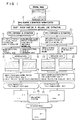
- the modification of pixel value of the differential image is conducted (process 6 in Fig. 1).
- the reason is that the central portion and peripheral portion of the welding line are different in brightness even for the same defect and thus an inspector has different sensitivities for brightness.
- a psychological adjustment of sensitivity is predicated to take place so that the central portion and peripheral portion of the welding line are sensed in the same brightness.
- a statistic value of the brightness of the differential image is taken thereby to implement the process equivalent to the inspector's behavior so that the central portion and peripheral portion have equal sensitivity of brightness in terms of the degree of variance, and the same result as of the inspector's inspection is realized.
- the range of object for evaluating the statistic value of the overall image is confined to the interior of the welding line 20 as shown in Fig. 2, so that the statistic value which is unrelated to the sampling area can be evaluated without the influence of the base metal.
- Two regions X and Y of Fig. 2 are set so that the statistic value in the range is made controllable as a parameter of image processing.
- a certain logarithmic conversion for the brightness is conducted with the intention of conversion of the pixel value to the value which is proportional to the magnitude of human's visual sensitivity.
- the modified pixel value of defect image is predicated to have been converted to a value which corresponds to the sensitivity of psychological sense of the inspector. Based on this fact, for the modified image, the mean value and standard deviation are evaluated for the statistic value of the brightness distribution of the overall image thereby to determine the threshold value by calculating the mean value of brightness subtracted by the standard deviation multiplied by a (where a is a parameter), and pixels having brightness smaller than or equal to the threshold value are extracted as candidates of defect (process 9 in Fig. 1).
- a region extracted based on this threshold value can only be an extremely dark portion of the image in some case, and the region is further shaped by expanding the region so that pixels with value of brightness smaller than or equal to the threshold value plus standard deviation divided by b (where b is a parameter) in the peripheral portion of the extraction region are included.
- the result of extraction in this manner is virtually identical to the result of extraction implemented by the inspector.
- the quadratic approximation for the change of brightness in the residual portion is implemented not only in the direction normal to the welding line, but also in the direction of welding line, as shown in process 7 in Fig. 1.
- the quadratic approximation for the change of brightness in the residual portion is implemented not only in the direction normal to the welding line, but also in the direction of welding line, as shown in process 7 in Fig. 1.
- Images extracted automatically in this manner include an irrelevant indication, which is not an inherent defect image or a defect other than a candidate defect, but is an irrelevant indication caused by a dark shadow or noise in contrast to a portion of sharp variation in brightness, and an irrelevant indication caused by the influence of a special image processing, and these irrelevant indications need to be removed.
- the feature value of defect on the film image is measured, and the result is compared with the irrelevant indication removal rule in the irrelevant indication database which has been collected in advance by the inspector, thereby eliminating the irrelevant indication.
- the emphasizing and extraction of a defect image which is elongated in the lateral direction along the planar welding line, such as a lack of fusion of type 2 are conducted.
- the emphasizing process for the brightness change in the direction of welding line is carried out as shown by the process 10 in Fig. 1. Because of a weak contrast of the image on the film as compared with a blow hole or the like of the type-1 defect, the use of the same method as for type 1 is inconvenient in that emphasizing is not possible due to the overwhelming brightness distribution of the background.
- a rectangular window 22 is formed for a pixel 21 in attention at the center, the mean value of brightness in the window 22 is evaluated, and the brightness of the pixel 21 in attention is replaced with the mean value thereby to improve the contrast of defect image which is elongated in the lateral direction.
- a weighting factor -1 is multiplied to pixels that are distant by id pixels above and below the pixel 21 in attention and a weighting factor of 2 is multiplied to the central section, and these terms are totaled.
- emphasizing modification of the pixel value is conducted in the same manner as for a defect of type 1.
- the emphasizing modification for the image at the end of the residual portion is carried out as shown by the process 12 in Fig. 1.
- the process 12 implements the modification based on the logarithmic conversion so that the standard deviation ⁇ of the residual end section (low brightness portion is equal to the standard deviation ⁇ ' of the welding center section (high brightness portion).
- the binary conversion of candidate defect image, shaping and irrelevant indication removal processes shown by the process 14 in Fig. 1 are carried out concurrently in the same manner as for the candidate defect image of type 1 described previously.
- the extraction result 15 for the candidate defect image of type 2 is obtained.
- the process of candidate defect image of the case where the extraction regions do not overlap is to retain all extracted regions of defect images of type 1 and to retain defect images of type 2 with the extraction region having a vertical to horizontal ratio of three or more or a length to width ratio in the inertial main axis direction of region of three or more, and to remove the remainder.
- the process for a candidate defect image of the case where the extraction regions overlap is the selection based on the vertical to horizontal ratio of the extraction region, the selection based on the area, or the selection based on the distribution of brightness in the extraction region of the original image.
- Candidate defect image of type 2 o Discrimination of irrelevant indication based on the presence of absence of a higher density portion in the candidate image than in the peripheral portion. o Discrimination of typical defects of type 2 (e.g., lack of fusion and faulty connection) based on the length, contrast of density and linearity of candidate image. o Deletion of defects with small lengths.
- a candidate defect image before the application of the irrelevant indication removal rule shown in Table 1 to the result of extraction of a defect image which has been rendered the emphasized extraction process is shown in Fig. 6, and a candidate defect image after the application of the rule is shown in Fig. 7.
- Images which undergo the image processing are not only images formed on the radiographic film, but images which are introduced directly through the image intensifier can also be applicable, as mentioned previously.
- the radiographic test using the X rays or the like for such a weld defect as a blow hole and lack of fusion emerging in the welded portion or the like of a pipe or the like of a power plant facility it is possible to extract a defective portion automatically and measure the shape and size of the defect automatically thereby to speed up the inspection and enhance the stability of the judgement result.
- the result of extraction is consistent with the result of the inspector. Setting of the threshold value of extraction is easy, and over sensitivity detection of defect images caused by the irrelevant indication removal process can be prevented.
- the level of a candidate defect image including a defect image in the image can be defined in terms of the deviation value, whereby setting of the threshold value at the extraction of defect image is made easy.
- an emphasized image converted into binary through the calculation of statistic value of pixel values of modified, emphasized image and subtraction of the threshold value multiplied by a certain parameter of the standard deviation from the mean value so that part of the candidate defect image can be extracted is conceivable to have a virtual normal distribution, and therefore the above-mentioned value of multiple of the standard deviation can be set easily by adjustment in the manner of probability.
Landscapes
- Engineering & Computer Science (AREA)
- General Physics & Mathematics (AREA)
- Health & Medical Sciences (AREA)
- Physics & Mathematics (AREA)
- Immunology (AREA)
- Biochemistry (AREA)
- General Health & Medical Sciences (AREA)
- Analytical Chemistry (AREA)
- Chemical & Material Sciences (AREA)
- Pathology (AREA)
- Life Sciences & Earth Sciences (AREA)
- Toxicology (AREA)
- Mechanical Engineering (AREA)
- Quality & Reliability (AREA)
- Computer Vision & Pattern Recognition (AREA)
- Theoretical Computer Science (AREA)
- Analysing Materials By The Use Of Radiation (AREA)
Description
| Object defect image | Basis of image information on defect or irrelevant indication |
| Candidate defect image of type 1 | o Discrimination of irrelevant indication based on the presence or absence of the density difference between the candidate image and its periphery (above, below, right, left). |
| o Discrimination of typical defect images with strong contrast of density (e.g., blow hole). | |
| o Discrimination of irrelevant indication based on the position of candidate image (residual end section or welding line central section). | |
| o Discrimination of irrelevant indication appearing in parallel along the border line between the residual portion and base metal. | |
| o Deletion of small defects other than densed blow holes. | |
| Candidate defect image of type 2 | o Discrimination of irrelevant indication based on the presence of absence of a higher density portion in the candidate image than in the peripheral portion. |
| o Discrimination of typical defects of type 2 (e.g., lack of fusion and faulty connection) based on the length, contrast of density and linearity of candidate image. | |
| o Deletion of defects with small lengths. |
Claims (6)
- Method for automatically extracting a weld defect image based on a radiographic transmission test in which
data of an image taken by the radiographic transmission test is input into a computer and as preprocessing of said image data, noises are removed from said image data, an object area is sampled from said image data and a welding line portion (2) in the object area is extracted (4) , whereinto obtain an image of a defect of type 1 being a volumetric defect, an emphasizing process based on the quadratic curve approximation of the brightness distribution is conducted (5, 7) in order to obtain an intermediary defect image, the original image is subtracted from the intermediary defect image, an emphasizing modification of the resulting differential image (6, 8) is performed and an automatic extraction of a candidate defect image and a removal of an irrelevant indication image are conducted (9, 11), andto obtain an image of a defect of type 2 being a defect elongated in a lateral direction along a planar welding line an emphasizing process based on a filtering process emphasizing the brightness conversion along the welding line is conducted (10), an emphasizing modification of the resulting image is performed (12, 13) and an automatic extraction of a candidate defect image and removal of an irrelevant indication image are conducted (14, 15);the defects of type 1 and type 2 are obtained in parallel, andthe candidate images of defects of type 1 and type 2 are merged (16). - Method according to claim 1, wherein a quadratic curve approximation process in the direction of the welding line is conducted concurrently to the modification of a pixel value following the differential process in the direction normal to the welding line of the defect image of type 1, and the modification of the pixel value of the differential image is conducted after the differential process.
- Method according to claim 1, wherein the emphasizing modification for a welding line central image and a residual end image is carried out concurrently following the emphasizing process of the brightness variation in the direction normal to the welding line of the defect image of type 2.
- Method according to claim 1, wherein said irrelevant indication image is removed based on the comparison of measured data of the feature value of defect with a database which is based on the experience of an inspector.
- Method according to claim 1, wherein said automatic extraction is carried out through a statistic process and binary conversion process for the brightness distribution.
- Apparatus for automatically extracting a weld defect image based on a radiographic transmission test, comprising
means for inputting data of an image taken by the radiographic transmission test into a computer and means for preprocessing said image data, which remove noises from said image data, sample an object area from said image data and extract a welding line portion (2) in the object area, whereinmeans are provided for obtaining an image of a defect of type 1 being a volumetric defect, which conduct an emphasizing process based on the quadratic curve approximation of the brightness distribution (5, 7) in order to obtain an intermediary defect image, subtract the original image from the intermediary defect image, perform an emphasizing modification of the resulting differential image (6, 8) and conduct an automatic extraction of a candidate defect image and a removal of an irrelevant indication image (9, 11),means are provided for obtaining an image of a defect of type 2 being a defect elongated in a lateral direction along a planar welding line, which conduct an emphasizing process based on a filtering process emphasizing the brightness conversion along the welding line (10), perform an emphasizing modification of the resulting image (12, 13) and conduct an automatic extraction of a candidate defect image and a removal of an irrelevant indication image (14, 15); andthe means for obtaining the defect of type 1 and the means for obtaining the defect of type 2 operate in parallel andmeans are provided for merging the candidate images of defects of type 1 and type 2.
Priority Applications (1)
| Application Number | Priority Date | Filing Date | Title |
|---|---|---|---|
| EP96112286A EP0742433A3 (en) | 1990-01-12 | 1991-01-14 | Method for processing radiographic image data to detect a welding defect |
Applications Claiming Priority (4)
| Application Number | Priority Date | Filing Date | Title |
|---|---|---|---|
| JP3509/90 | 1990-01-12 | ||
| JP2003508A JPH07119714B2 (en) | 1990-01-12 | 1990-01-12 | Weld defect type estimation method |
| JP350990A JPH07119713B2 (en) | 1990-01-12 | 1990-01-12 | Automatic extraction processing method of welding defect image in radiation test |
| JP3508/90 | 1990-01-12 |
Related Child Applications (1)
| Application Number | Title | Priority Date | Filing Date |
|---|---|---|---|
| EP96112286A Division EP0742433A3 (en) | 1990-01-12 | 1991-01-14 | Method for processing radiographic image data to detect a welding defect |
Publications (3)
| Publication Number | Publication Date |
|---|---|
| EP0437280A2 EP0437280A2 (en) | 1991-07-17 |
| EP0437280A3 EP0437280A3 (en) | 1993-07-07 |
| EP0437280B1 true EP0437280B1 (en) | 1998-04-22 |
Family
ID=26337100
Family Applications (2)
| Application Number | Title | Priority Date | Filing Date |
|---|---|---|---|
| EP91100359A Expired - Lifetime EP0437280B1 (en) | 1990-01-12 | 1991-01-14 | A method of processing radiographic image data for detecting a defect of welding |
| EP96112286A Withdrawn EP0742433A3 (en) | 1990-01-12 | 1991-01-14 | Method for processing radiographic image data to detect a welding defect |
Family Applications After (1)
| Application Number | Title | Priority Date | Filing Date |
|---|---|---|---|
| EP96112286A Withdrawn EP0742433A3 (en) | 1990-01-12 | 1991-01-14 | Method for processing radiographic image data to detect a welding defect |
Country Status (4)
| Country | Link |
|---|---|
| US (1) | US5182775A (en) |
| EP (2) | EP0437280B1 (en) |
| DE (1) | DE69129275T2 (en) |
| DK (1) | DK0437280T3 (en) |
Families Citing this family (48)
| Publication number | Priority date | Publication date | Assignee | Title |
|---|---|---|---|---|
| JP3123146B2 (en) * | 1991-09-11 | 2001-01-09 | トヨタ自動車株式会社 | Weld bead quality inspection equipment |
| US5345514A (en) * | 1991-09-16 | 1994-09-06 | General Electric Company | Method for inspecting components having complex geometric shapes |
| US5555316A (en) * | 1992-06-30 | 1996-09-10 | Matsushita Electric Industrial Co., Ltd. | Inspecting apparatus of mounting state of component or printing state of cream solder in mounting line of electronic component |
| US5991435A (en) * | 1992-06-30 | 1999-11-23 | Matsushita Electric Industrial Co., Ltd. | Inspecting apparatus of mounting state of component or printing state of cream solder in mounting line of electronic component |
| CN1133633A (en) * | 1993-10-26 | 1996-10-16 | 旭化成工业株式会社 | Measuring method and device for gloss unevenness and printing unevenness |
| JP3363735B2 (en) * | 1996-06-26 | 2003-01-08 | 松下電器産業株式会社 | X-ray imaging device |
| FR2763686B1 (en) * | 1997-05-22 | 1999-07-02 | Commissariat Energie Atomique | METHOD AND DEVICE FOR PROCESSING WELDING RADIOGRAMS FOR DETECTION OF WELDING DEFECTS |
| US6137860A (en) * | 1998-08-18 | 2000-10-24 | Lockheed Martin Corporation | Digital radiographic weld inspection system |
| EP1126729A1 (en) * | 2000-02-18 | 2001-08-22 | STMicroelectronics S.r.l. | A process for estimating the noise level in sequences of images and a device therefor |
| KR20020064903A (en) * | 2000-09-18 | 2002-08-10 | 올림파스 고가꾸 고교 가부시키가이샤 | Image data file management system and method |
| WO2003062809A1 (en) * | 2002-01-23 | 2003-07-31 | Marena Systems Corporation | Infrared thermography for defect detection and analysis |
| FR2862803B1 (en) * | 2003-11-24 | 2007-12-07 | Franco Belge Combustibles | METHOD FOR NON-DESTRUCTIVE CONTROL OF AN ELEMENT FOR NUCLEAR REACTOR |
| JP3972941B2 (en) * | 2004-06-30 | 2007-09-05 | オムロン株式会社 | Solder printing inspection method for component mounting board and inspection machine for solder printing inspection |
| US7436992B2 (en) * | 2004-07-30 | 2008-10-14 | General Electric Company | Methods and apparatus for testing a component |
| US8013599B2 (en) * | 2004-11-19 | 2011-09-06 | General Electric Company | Methods and apparatus for testing a component |
| US7233867B2 (en) * | 2005-04-06 | 2007-06-19 | General Electric Company | Eddy current inspection method and system |
| US7873237B2 (en) * | 2006-02-17 | 2011-01-18 | Dassault Systèmes | Degrading 3D information |
| US20080088621A1 (en) * | 2006-10-11 | 2008-04-17 | Jean-Jacques Grimaud | Follower method for three dimensional images |
| US7529336B2 (en) | 2007-05-31 | 2009-05-05 | Test Research, Inc. | System and method for laminography inspection |
| CA2643219C (en) * | 2007-12-21 | 2017-08-22 | Knight, Inc. | System, method and program product to screen for longitudinal-seam anomalies |
| US10546372B2 (en) | 2007-12-21 | 2020-01-28 | Kinder Morgan, Inc. | Method, machine, and computer medium having computer program to detect and evaluate structural anomalies in circumferentially welded pipelines |
| EP2380015A4 (en) | 2008-12-30 | 2016-10-26 | Sikorsky Aircraft Corp | Non-destructive inspection method with objective evaluation |
| US20100169053A1 (en) * | 2008-12-30 | 2010-07-01 | Caterpillar Inc. | Method for creating weldment inspection documents |
| CN102175700B (en) * | 2011-01-20 | 2012-07-25 | 山东大学 | Method for detecting welding seam segmentation and defects of digital X-ray images |
| CA2828584C (en) | 2012-09-27 | 2018-10-23 | Kinder Morgan, Inc. | System, method and computer medium having computer program to determine presence of stress corrosion cracking in pipelines with pattern recognition |
| JP6031339B2 (en) * | 2012-11-21 | 2016-11-24 | 富士フイルム株式会社 | Perspective image density correction method, nondestructive inspection method, and image processing apparatus |
| US9180552B2 (en) * | 2013-05-27 | 2015-11-10 | ThinkSmart IT Solutions Private Limited | System and method for identifying defects in welds by processing X-ray images |
| CN104749184B (en) * | 2013-12-31 | 2018-08-21 | 研祥智能科技股份有限公司 | Automatic optical detection method and system |
| CN104897701A (en) * | 2015-06-19 | 2015-09-09 | 国核电站运行服务技术有限公司 | Radiographic testing method for local thinning of valve body |
| JP2017054337A (en) * | 2015-09-10 | 2017-03-16 | ソニー株式会社 | Image processor and method |
| CN105486702B (en) * | 2015-12-07 | 2018-06-26 | 苏州科耐视智能科技有限公司 | A kind of target defect detecting system based on X ray |
| KR102018330B1 (en) * | 2017-04-11 | 2019-09-05 | 한국전자통신연구원 | Apparatus and method for detecting anomaly behavior in plant pipe using multiple meta-learning |
| CN108956617A (en) * | 2018-06-04 | 2018-12-07 | 温州大学 | A kind of detection method of the electronic device solder joint thermal cycle failure based on micro- deformation Intelligence Classifier |
| US12203873B2 (en) * | 2019-07-08 | 2025-01-21 | Worldwide Nondestructive Testing, Inc. | System and method for inspecting fused plastic pipes |
| US11448604B2 (en) * | 2019-07-08 | 2022-09-20 | Worldwide Nondestructive Testing, Inc. | System and method for inspecting fused plastic pipes |
| FR3111703B1 (en) * | 2020-06-18 | 2022-05-20 | Skf Svenska Kullagerfab Ab | Method for detecting a critical fault for a rolling element made of ceramic material |
| US11668660B2 (en) * | 2020-09-29 | 2023-06-06 | Varex Imaging Corporation | Radiographic inspection system for pipes and other structures and material loss estimation |
| CN113808094A (en) * | 2021-09-10 | 2021-12-17 | 武汉联开检测科技有限公司 | Ray detection welding defect image rating system and method |
| KR102390004B1 (en) | 2021-09-16 | 2022-04-25 | 라이트브라더스 주식회사 | Apparatus, method and computer-readable storage medium for non-destructive inspection of bicycle based on analyzing amount of scale change |
| CN113763294B (en) * | 2021-09-26 | 2023-08-08 | 上海航天精密机械研究所 | Fast preprocessing method and system of weld seam image based on dynamic CLAHE |
| CN114593871A (en) * | 2022-02-28 | 2022-06-07 | 陕西省天然气股份有限公司 | Pipeline valve internal leakage detection device and detection method based on digital rays |
| CN114663365A (en) * | 2022-03-04 | 2022-06-24 | 重庆中科云从科技有限公司 | Defect detection method, device and computer storage medium |
| CN115063422B (en) * | 2022-08-18 | 2022-11-08 | 建首(山东)钢材加工有限公司 | Intelligent detection method for container welding quality |
| CN116433669B (en) * | 2023-06-14 | 2023-08-18 | 山东兴华钢结构有限公司 | Machine vision-based quality detection method for weld joints of steel frame of anti-seismic structure |
| CN117086465B (en) * | 2023-09-27 | 2024-10-11 | 盐城工学院 | Friction stir welding robot control method and system based on AI technology |
| CN118096753B (en) * | 2024-04-26 | 2024-08-06 | 陕西正鑫工程材料股份有限公司 | Ladder protection cage molding assembly defect identification method based on image processing |
| CN118357814B (en) * | 2024-06-19 | 2024-09-10 | 风凯换热器制造(常州)有限公司 | Weld polishing flatness detection method and system |
| CN120318605B (en) * | 2025-06-16 | 2025-09-09 | 深圳市信润富联数字科技有限公司 | Welding parameter adjustment method and device, storage medium, and electronic device |
Family Cites Families (9)
| Publication number | Priority date | Publication date | Assignee | Title |
|---|---|---|---|---|
| JPS4939477A (en) * | 1972-08-12 | 1974-04-12 | ||
| JPS5981544A (en) * | 1982-11-01 | 1984-05-11 | Nireko:Kk | Detecting method of internal defect |
| HU190197B (en) * | 1983-12-05 | 1986-08-28 | Kohaszati Gyarepitoe Vallalat,Hu | Method and device for testing quality of the welds by videoradiography |
| DE3533913A1 (en) * | 1985-09-23 | 1987-04-02 | Muenchener Apparatebau Fuer El | Arrangement for nondestructive testing of welded seams |
| US4809308A (en) * | 1986-02-20 | 1989-02-28 | Irt Corporation | Method and apparatus for performing automated circuit board solder quality inspections |
| US4926452A (en) * | 1987-10-30 | 1990-05-15 | Four Pi Systems Corporation | Automated laminography system for inspection of electronics |
| US4896278A (en) * | 1988-07-11 | 1990-01-23 | Northrop Corporation | Automated defect recognition system |
| JPH02148180A (en) * | 1988-11-29 | 1990-06-07 | Nippon Seiko Kk | Pattern inspection method and device |
| US5058178A (en) * | 1989-12-21 | 1991-10-15 | At&T Bell Laboratories | Method and apparatus for inspection of specular, three-dimensional features |
-
1991
- 1991-01-11 US US07/639,872 patent/US5182775A/en not_active Expired - Lifetime
- 1991-01-14 EP EP91100359A patent/EP0437280B1/en not_active Expired - Lifetime
- 1991-01-14 DK DK91100359T patent/DK0437280T3/en active
- 1991-01-14 EP EP96112286A patent/EP0742433A3/en not_active Withdrawn
- 1991-01-14 DE DE69129275T patent/DE69129275T2/en not_active Expired - Fee Related
Also Published As
| Publication number | Publication date |
|---|---|
| EP0742433A2 (en) | 1996-11-13 |
| EP0437280A2 (en) | 1991-07-17 |
| DE69129275D1 (en) | 1998-05-28 |
| EP0437280A3 (en) | 1993-07-07 |
| DK0437280T3 (en) | 1998-10-05 |
| DE69129275T2 (en) | 1998-10-08 |
| EP0742433A3 (en) | 1997-09-17 |
| US5182775A (en) | 1993-01-26 |
Similar Documents
| Publication | Publication Date | Title |
|---|---|---|
| EP0742433A2 (en) | A method of processing radiographic image data for detecting a defect of welding | |
| CA2130340C (en) | Method for identifying objects using data processing techniques | |
| JPH06229943A (en) | Processing method for detecting and mapping contamination on surface of photograph member | |
| CN106556611A (en) | Chromatograp defect automatic checkout system and detection method based on machine vision | |
| Mery | Crossing line profile: a new approach to detecting defects in aluminium die casting | |
| CN108802052A (en) | A kind of detecting system and its detection method about slide fastener defect | |
| CN121033057A (en) | A method and system for detecting defects in light guide plates based on neural networks | |
| CN120598968A (en) | A defect detection method combining vision and X-ray detection technology | |
| CN121147870B (en) | Automatic intelligent road quality detection method and system based on machine identification | |
| JP4318776B2 (en) | Nonuniformity inspection method and apparatus | |
| Palakal et al. | Intelligent computational methods for corrosion damage assessment | |
| JPH03209583A (en) | Automatic extraction processing method for welding defect image in radiation test | |
| JPH08261951A (en) | Surface flaw inspection method and apparatus | |
| CN117705754B (en) | Textile polyester fiber content online detection method based on hyperspectral imaging | |
| JPH06116914A (en) | Method and apparatus for diagnosing coating film deterioration | |
| Rale et al. | Comparison of different ANN techniques for automatic defect detection in X-Ray images | |
| CN121616898B (en) | A classification method for livestock and veterinary waste based on image processing | |
| CN120064300B (en) | A method and system for detecting ribbon defects based on machine vision | |
| CN121213519B (en) | Bolt shrinkage porosity defect detection method applied to medical instrument | |
| JPH06233013A (en) | Image quality evaluation method | |
| CN117789182B (en) | Industrial instrument data acquisition method and system | |
| Wood et al. | Detection and labeling of retinal vessels for longitudinal studies | |
| JP3297945B2 (en) | Steel sheet surface defect detection method | |
| KR100234732B1 (en) | Apparatus and method for analysing shape deformation using fringe | |
| CN108122226A (en) | A kind of detection method and device of glass defect |
Legal Events
| Date | Code | Title | Description |
|---|---|---|---|
| PUAI | Public reference made under article 153(3) epc to a published international application that has entered the european phase |
Free format text: ORIGINAL CODE: 0009012 |
|
| AK | Designated contracting states |
Kind code of ref document: A2 Designated state(s): DE DK FR GB NL |
|
| PUAL | Search report despatched |
Free format text: ORIGINAL CODE: 0009013 |
|
| AK | Designated contracting states |
Kind code of ref document: A3 Designated state(s): DE DK FR GB NL |
|
| 17P | Request for examination filed |
Effective date: 19930729 |
|
| 17Q | First examination report despatched |
Effective date: 19950523 |
|
| GRAG | Despatch of communication of intention to grant |
Free format text: ORIGINAL CODE: EPIDOS AGRA |
|
| GRAG | Despatch of communication of intention to grant |
Free format text: ORIGINAL CODE: EPIDOS AGRA |
|
| GRAH | Despatch of communication of intention to grant a patent |
Free format text: ORIGINAL CODE: EPIDOS IGRA |
|
| GRAH | Despatch of communication of intention to grant a patent |
Free format text: ORIGINAL CODE: EPIDOS IGRA |
|
| GRAA | (expected) grant |
Free format text: ORIGINAL CODE: 0009210 |
|
| AK | Designated contracting states |
Kind code of ref document: B1 Designated state(s): DE DK FR GB NL |
|
| XX | Miscellaneous (additional remarks) |
Free format text: TEILANMELDUNG 96112286.8 EINGEREICHT AM 30/07/96. |
|
| REF | Corresponds to: |
Ref document number: 69129275 Country of ref document: DE Date of ref document: 19980528 |
|
| ET | Fr: translation filed | ||
| REG | Reference to a national code |
Ref country code: DK Ref legal event code: T3 |
|
| PLBE | No opposition filed within time limit |
Free format text: ORIGINAL CODE: 0009261 |
|
| STAA | Information on the status of an ep patent application or granted ep patent |
Free format text: STATUS: NO OPPOSITION FILED WITHIN TIME LIMIT |
|
| 26N | No opposition filed | ||
| REG | Reference to a national code |
Ref country code: GB Ref legal event code: IF02 |
|
| PGFP | Annual fee paid to national office [announced via postgrant information from national office to epo] |
Ref country code: DK Payment date: 20020104 Year of fee payment: 12 |
|
| PGFP | Annual fee paid to national office [announced via postgrant information from national office to epo] |
Ref country code: GB Payment date: 20020116 Year of fee payment: 12 |
|
| PGFP | Annual fee paid to national office [announced via postgrant information from national office to epo] |
Ref country code: FR Payment date: 20020129 Year of fee payment: 12 |
|
| PGFP | Annual fee paid to national office [announced via postgrant information from national office to epo] |
Ref country code: NL Payment date: 20020131 Year of fee payment: 12 |
|
| PGFP | Annual fee paid to national office [announced via postgrant information from national office to epo] |
Ref country code: DE Payment date: 20020328 Year of fee payment: 12 |
|
| PG25 | Lapsed in a contracting state [announced via postgrant information from national office to epo] |
Ref country code: GB Free format text: LAPSE BECAUSE OF NON-PAYMENT OF DUE FEES Effective date: 20030114 |
|
| PG25 | Lapsed in a contracting state [announced via postgrant information from national office to epo] |
Ref country code: DK Free format text: LAPSE BECAUSE OF NON-PAYMENT OF DUE FEES Effective date: 20030131 |
|
| PG25 | Lapsed in a contracting state [announced via postgrant information from national office to epo] |
Ref country code: NL Free format text: LAPSE BECAUSE OF NON-PAYMENT OF DUE FEES Effective date: 20030801 Ref country code: DE Free format text: LAPSE BECAUSE OF NON-PAYMENT OF DUE FEES Effective date: 20030801 |
|
| GBPC | Gb: european patent ceased through non-payment of renewal fee | ||
| REG | Reference to a national code |
Ref country code: DK Ref legal event code: EBP |
|
| PG25 | Lapsed in a contracting state [announced via postgrant information from national office to epo] |
Ref country code: FR Free format text: LAPSE BECAUSE OF NON-PAYMENT OF DUE FEES Effective date: 20030930 |
|
| NLV4 | Nl: lapsed or anulled due to non-payment of the annual fee |
Effective date: 20030801 |
|
| REG | Reference to a national code |
Ref country code: FR Ref legal event code: ST |