EP0437265B1 - Quenching tower gas outlet flue of coke dry quenching equipment - Google Patents
Quenching tower gas outlet flue of coke dry quenching equipment Download PDFInfo
- Publication number
- EP0437265B1 EP0437265B1 EP91100272A EP91100272A EP0437265B1 EP 0437265 B1 EP0437265 B1 EP 0437265B1 EP 91100272 A EP91100272 A EP 91100272A EP 91100272 A EP91100272 A EP 91100272A EP 0437265 B1 EP0437265 B1 EP 0437265B1
- Authority
- EP
- European Patent Office
- Prior art keywords
- coke
- wall
- exhaust port
- quenching
- tower
- Prior art date
- Legal status (The legal status is an assumption and is not a legal conclusion. Google has not performed a legal analysis and makes no representation as to the accuracy of the status listed.)
- Expired - Lifetime
Links
Images



Classifications
-
- C—CHEMISTRY; METALLURGY
- C10—PETROLEUM, GAS OR COKE INDUSTRIES; TECHNICAL GASES CONTAINING CARBON MONOXIDE; FUELS; LUBRICANTS; PEAT
- C10B—DESTRUCTIVE DISTILLATION OF CARBONACEOUS MATERIALS FOR PRODUCTION OF GAS, COKE, TAR, OR SIMILAR MATERIALS
- C10B39/00—Cooling or quenching coke
- C10B39/02—Dry cooling outside the oven
Definitions
- This invention relates to a gas outlet flue which minimizes coke powdery particles carried by a discharge gas stream when a high temperature gas heated through heat-exchange with red-hot coke in a quenching tower of a coke dry quenching equipment is sent out to a heat-exchanger such as a boiler.
- a coke dry quenching equipment having a sensible heat recovering system of the type that stores the red-hot coke charged in batch into the quenching tower temporarily in a pre-chamber and then drops the coke continuously from this pre-chamber into a cooling zone.
- Fig. 15 shows a coke dry quenching equipment equipped with this sensible heat recovery system.
- the red-hot coke from the coke oven is charged into the pre-chamber 3 via a charging port 2 disposed at the top of the quenching tower 1, and drops sequentially into a cooling chamber 4 located below, where the coke is cooled to about 200 °C through heat-exchange with inert gas blown in via a gas blast port 5.
- the coke thus cooled is discharged a discharging apparatus 7 via a discharge port 6.
- the inert gas heated to about 800 °C through the heat-exchange is collected through a ring duct 9 via an exhaust port 8 and is introduced into a boiler 11 through a duct 10. Water is supplied into the boiler 11 through an inflow pipe 12 and is taken out through an outflow pipe 13 as hot water or steam that has absorbed the retention heat of the inert gas sent from the duct 10.
- a dust collector 14 is disposed at an intermediate portion of the duct 10 in order to remove the coke powder particles and dust remaining in the inert gas.
- the coke powder particles and dust separated by the dust collector 14 from the inert gas are taken off outside the system through the discharge pipe 15.
- the dust collector 14 disposed inside the duct includes a collision plate 16 which is disposed so as to project into an intermediate potion of the gas flow path in such a way that the coke powder particles and dust floating in the inert gas collide therewith, and has a sectional area of its flow path enlarged near the collision plate 16.
- the dust collector 14 of this type has the advantages that the structure is simple and maintenance load can be reduced. However, when the quantities of the coke powder particles and dust carried by the inert gas flowing out via the exhaust port 8 increase, this dust collector 14 cannot collect them satisfactorily and part of the coke powder particles and dust tend to flow into the boiler 11. If the inert gas includes coke lumps they will cause clogging of the exhaust port 8, prohibiting continuous operation of the equipment any longer.
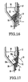
- the conventional exhaust port 8 is so designed that the inner surfaces of columnar walls 18 extend continuously from the inner surface of an upper wall 17 to the inner surface of a lower wall 19 to partition the exhaust port 8 as shown in Fig. 16.
- individual brick blocks are laid up vertically from the lower wall 19 to the upper wall 17 so as to form the columnar walls 18.
- the angle of inclination ⁇ of the columnar wall 18 cannot be made small from the structural limitation. Therefore, the angle of inclination ⁇ of the columnar wall 18 is greater than an angle of repose of the coke lumps 20 that descend inside the chamber.
- the coke lumps 20 and coke powder particles descend inside the quenching tower 1 come under an inclined state into part of the exhaust port 8 from the lower end of the upper wall 17, thus accumulating in a thicker layer toward the top end of the lower wall 19.
- the coke lumps and powder particles entering the exhaust port 8 lower near the upper end of the lower wall 19 can hardly escape out from the exhaust port due to the friction with the brick working of the lower wall 19 and the side pressure exerted on the cokes.
- part of the coke lumps and coke powder particles carried by the inert gas stream accumulate near the upper end of the lower wall 19 from where the coke lumps and coke powder particles can hardly flow out so that the occupation ratio by the coke lumps and coke powder particles there increases to lower the vacancy ratio.
- the inert gas stream 21 rising from below the cooling chamber 4 to the exhaust port 8 will have a more increased flow rate at portions closer to the lower end of the upper wall 17 where the gas flow resistance is smaller, namely the accumulation layer thickness is smaller and the vacancy ratio is higher. Therefore, the gas flow rate near the lower end of the upper wall 17 increases beyond the predetermined value and the coke lumps 20 and the coke powder particles are blown by the inert gas stream and a greater portion of the coke lumps and coke powder particles is brought into the ring duct 9.
- the scattering of the coke lumps 20 and the coke powder particles becomes more remarkable as the amount of the inert gas blown into the quenching tower 1 is increased as necessitated by an increased capacity of the plant.
- Japanese Laid-Open patent Application No. Sho 62-250090 discloses restriction of the scattering of the coke lumps, coke powder particles, and the like, by partitioning the exhaust port 8 into multiple stages by a plurality of, or a single, partition walls 22, as shown in Fig. 17. Due to this partition wall 22, the coke lumps 20 inside the exhaust port 8 form the surface 20a above the partition wall 22 and the surface 20b below the partition wall 22.
- this deposition of the coke lumps 20 is compared with the deposition shown in Fig. 16, it can be seen that the thickness of deposition of the coke lumps 20 when viewed in the flowing direction of the inert gas stream 21 is about a half.
- the difference in the gas stream resistance between the portion immediately below the upper wall 17 and the portion immediately above the partition wall 22 and that between the portion immediately below the partition wall 22 and the portion immediately above the lower wall 19 are small and the tendency of concentration of the inert gas stream 21 on the portion immediately below the upper wall 17 and on the portion immediately below the partition wall 22 can be restricted, too.
- the amounts of the coke lumps 20 and coke powder particles blown off by the inert gas stream 21 can be reduced, too.
- the partition wall 22 is disposed, for example, in such a manner as to project from the side surface of the columnar wall 18. For this reason, bricks of special shape are required for the columnar wall 18 and it is by no means easy to apply this technique to existing equipments.
- partition wall 22 As one partition wall 22 is supported by the adjacent two columnar portions 8, when the individual columnar walls 18 move by themselves due to their own thermal expansion and other factors, the partition wall 22 cracks or is damaged. If this is repeated so many times due to the temperature fluctuations caused by changes in the operational conditions, the partition wall may fall down in the worst case.
- the present invention has its object to prevent the inert gas flowing through the exhaust port from concentrating locally along the upper wall side and to suppress the accompanying with the gas stream of the coke lumps and coke powder particles by providing a structure on the lower wall side which can lead out the accumulated coke powder particles and positively permit the inert gas stream therethrough.
- the quenching tower gas flue according to the present invention is characterized as below.
- a quenching tower gas outlet flue comprising an exhaust port for connecting between a cooling chamber in a quenching tower and a ring duct disposed around said tower, said port being partitioned by a lower wall, an upper wall and a columnar wall of said quenching tower, and a plurality of grooves extending in a flow path direction of an inert gas stream passing through said exhaust port, said grooves being formed at least on said lower wall serving as an inlet of said exhaust port.
- a quenching tower gas outlet flue comprising an exhaust port for connecting between a cooling chamber of a quenching tower and a ring duct disposed around said tower, said port being partitioned by a lower wall, an upper wall, and a columnar wall of said quenching tower, and a plurality of bricks of I-shape disposed side by side at least on said lower wall serving as an inlet portion of said port to form a plurality of grooves extending in a flow direction of an inert gas stream passing through said port.
- a quenching tower gas outlet flue comprising an exhaust port connecting between a cooling chamber in a quenching tower and a ring duct disposed around said tower, said port being partitioned by a lower wall, an upper wall and a columnar wall of said quenching tower, and a plurality of vacancies formed at least in said lower tower wall serving as an inlet of said port, said plurality of vacancies extending in a flow direction of an inert gas stream passing through said port and communicating to said exhaust port via a narrow path.
- Fig. 1 through 4 show an embodiment of the present gas outlet flue, wherein grooves are formed by arrangement of I-shape bricks on a lower wall 19 constituting part of an exhaust port 8.
- same reference numerals are used to identify the same members in Fig. 16, and the reference numerals used in Figs. 15 and 16 will be used for convenience in the following description.
- a columnar wall 18 is disposed between an upper wall 17 and a lower wall 19 so as to define an exhaust port 8 in the same way as in Fig. 16.
- a plurality of columnar wall 18 are disposed in such a manner as to extend along the inner peripheral surface of the quenching tower 1 as shown in Fig. 15 and the spaces between these columnar walls 18 serve as the exhaust ports 8.
- a plurality of I-shape bricks 25 are disposed on the inner surface of the lower wall 19 forming the lower surface of the exhaust ports 8 in the flowing direction of an inert gas stream 21 as shown in Fig. 2.
- the groove portion 23 comprising vacancies 26a and narrow paths 26b connecting between the exhaust port 8 and the vacancies 26a, thereby the coke powder particles accumulating near the upper end of the lower wall 19 of the exhaust port 8 drop through the narrow paths 26b to the vacancies 26a and are conducted therefrom into the cooling chamber 4 so that the amount of the coke powder particles accumulating these portions decreases, thus minimizing the lowering of the vacancy ratio.
- the vacancies 26a of the groove portion 23 contribute not only to lead out the coke powder particles but also to form a flow path through which the inert gas passes. As the result, the tendency of the inert gas to concentrate just below the upper wall 17 is restricted so that the amount of the coke lumps and coke powder particles blown off by the inert gas stream decreases.
- the vacancies of the groove portion formed in the lower wall 19 ought to lead out the coke powder particles dropping therein into the cooling chamber 4 and form a flow path for the inert gas stream 21, the larger size of the vacancies is more preferable.
- the narrow paths ought to permit only the coke particles 31 accumulating near the top end of the lower wall to drop into the vacancies 26a and to lead out the inert gas flowing through the vacancies 26a for convenience into the exhaust port 8, it is preferable the vacancies have a maximum size which prohibits the entrance of the coke lumps into the narrow paths.
- the coke lumps 20 have an average particle size of about 50 to 60 mm in diameter, and it is optimum that the narrow paths have a size of 10 to 30 mm, preferably about 20 mm which prohibits the dropping of the coke lumps therethrough.
- the spaces 26b may be partially or totally eliminated by bringing the upper portions of the adjacent bricks into mutual contact as shown in Fig. 5.
- the bricks are fixed in all directions by the adjacent bricks so that a more stabilized brick structure can be obtained.
- the shape of the vacancies 26a of the groove portion 23 may be a base-shape as shown in Fig. 6, and the groove portion 23 may be such as shown in Figs. 7 and 8, in which the vacancies and the narrow paths are integrated.
- Fig. 9 one example of the under-structure of the vacancies in the groove portion 23 is shown.
- the groove portion Even when the groove portion is formed on the inside of the lower wall, the coke powder particles cannot be led out from the groove portion and the groove portion 23 is clogged with the coke powder particles 31 if the under-structure is not appropriate.
- the groove portion thus cannot serve any more as the flow path for the inert gas stream 21 and, needless to say, it cannot lead out the coke powder particles.
- the under-structure of the groove portion 23 is very important for the formation of the groove portion.
- the angles ⁇ 1 and ⁇ 2 of the lower and upper inside surfaces of the groove portion are made larger than the repose angle of the coke and the angle ⁇ 1 of the lower inside surface is made larger than the angle ⁇ 2 of the circle formed by the lower end of the ceiling wall 32 forming the groove portion is smaller than the diameter of the cooling chamber by the value of "a" as shown in Fig. 9 so as to reduce the amount of the coke lumps which come into the groove portion 23 and reduce the resistance of the coke powder particles to the lead-out into the cooling chamber 4.
- the coke powder particles 31 fallen in the vacancies 26a of the groove portion 23 can be smoothly into led into the cooling chamber without stagnating in the vacancies 26a.
- the vacancies 26a of the groove portion are never clogged with the coke powder particles and part of the inert gas stream 21 rising upward from below the cooling chamber 4 can smoothly pass through the groove portion 23.
- Fig. 13 is a flow rate distribution diagram of the inert gas stream 21 passing through the exhaust port 8 when the lower surface of the exhaust port 8 is defined by the lower wall 19 provided on its slope surface with the groove portion 23 having vacancies 26a 50 mm in width and 100 mm in depth and narrow paths 26b of 20 mm in width, which extends in the direction of the inert gas stream 21.
- Fig. 13 is a flow rate distribution diagram of the inert gas stream 21 passing through the exhaust port 8 when the lower surface of the exhaust port 8 is defined by the lower wall 19 provided on its slope surface with the groove portion 23 having vacancies 26a 50 mm in width and 100 mm in depth and narrow paths 26b of 20 mm in width, which extends in the direction of the inert gas stream 21.
- the lowering of the vacancy ratio near the top end of the lower wall 19 is suppressed and since the inert gas stream 21 flows preferentially through the vacancies 26a defined between the lower wall 19 and the coke lumps 20, the flow rate of the inert gas stream 21 flowing along the upper wall 17 decreases and the flow rate distribution becomes uniform with respect to the cross-section of the exhaust port 8. Accordingly, the coke lumps 20 are not carried away by the inert gas stream 21 near the upper wall 17.
- the groove portion is formed on the lower wall forming the lower surface of the exhaust ports: the vacancies are defined between the coke lumps entering the inlet side of the exhaust ports and the lower wall and the narrow paths connecting the vacancies and the exhaust port are formed.
- the groove portion functions to conduct the coke powder particles, accumulating on the slope portion of the lower wall, out of the exhaust port into the cooling chamber so as to suppress the lowering of the vacancy ratio in this portion, and functions as the path for the inert gas streams.
- the flow rate of the inert gas stream passing along the upper wall decreases, the inert gas does not concentrate locally on the portion immediately below the upper wall and does not flow there at a high speed and the accompanying with the gas flow of the coke lumps and the coke powder particles can be restricted.
- the trouble resulting from those coke lumps and coke powder particles which are carried out from the cooling chamber can be avoided and a stable operation can be carried out even when the supply of the inert gas is increased for an increased capacity of the coke dry quenching equipment.
Landscapes
- Chemical & Material Sciences (AREA)
- Engineering & Computer Science (AREA)
- Materials Engineering (AREA)
- Oil, Petroleum & Natural Gas (AREA)
- Organic Chemistry (AREA)
- Coke Industry (AREA)
Description
- This invention relates to a gas outlet flue which minimizes coke powdery particles carried by a discharge gas stream when a high temperature gas heated through heat-exchange with red-hot coke in a quenching tower of a coke dry quenching equipment is sent out to a heat-exchanger such as a boiler.
- For quenching the red-hot coke while recovering the sensible heat of the red-hot coke extruded from a coke oven, a coke dry quenching equipment having a sensible heat recovering system of the type is known that stores the red-hot coke charged in batch into the quenching tower temporarily in a pre-chamber and then drops the coke continuously from this pre-chamber into a cooling zone.
- Fig. 15 shows a coke dry quenching equipment equipped with this sensible heat recovery system.
- The red-hot coke from the coke oven is charged into the
pre-chamber 3 via a charging port 2 disposed at the top of the quenching tower 1, and drops sequentially into acooling chamber 4 located below, where the coke is cooled to about 200 °C through heat-exchange with inert gas blown in via agas blast port 5. The coke thus cooled is discharged a discharging apparatus 7 via a discharge port 6. On the other hand, the inert gas heated to about 800 °C through the heat-exchange is collected through a ring duct 9 via anexhaust port 8 and is introduced into aboiler 11 through aduct 10. Water is supplied into theboiler 11 through aninflow pipe 12 and is taken out through anoutflow pipe 13 as hot water or steam that has absorbed the retention heat of the inert gas sent from theduct 10. - At this stage, large quantities of coke powder particles 31 and dust separated from the coke are floating in the inert gas flowing towards the
boiler 11 through theduct 10. If this inert gas is fed untreated into theboiler 11, heat transfer pipes inside theboiler 11 will be damaged and worn out due to friction and these coke powder particles and dust will deposit inside the boiler and will cause the failure of theboiler 11. Therefore, adust collector 14 is disposed at an intermediate portion of theduct 10 in order to remove the coke powder particles and dust remaining in the inert gas. The coke powder particles and dust separated by thedust collector 14 from the inert gas are taken off outside the system through thedischarge pipe 15. - The
dust collector 14 disposed inside the duct includes acollision plate 16 which is disposed so as to project into an intermediate potion of the gas flow path in such a way that the coke powder particles and dust floating in the inert gas collide therewith, and has a sectional area of its flow path enlarged near thecollision plate 16. Thedust collector 14 of this type has the advantages that the structure is simple and maintenance load can be reduced. However, when the quantities of the coke powder particles and dust carried by the inert gas flowing out via theexhaust port 8 increase, thisdust collector 14 cannot collect them satisfactorily and part of the coke powder particles and dust tend to flow into theboiler 11. If the inert gas includes coke lumps they will cause clogging of theexhaust port 8, prohibiting continuous operation of the equipment any longer. - Therefore, various improvements have been made to the cooling chamber structure of the
exhaust port 8 in order to prevent large quantities of coke powder particles and coke lumps from being entrapped in the inert gas flow rising inside the quenching tower 1 and flowing from theexhaust port 8 into the ring duct 9. - However, the
conventional exhaust port 8 is so designed that the inner surfaces ofcolumnar walls 18 extend continuously from the inner surface of anupper wall 17 to the inner surface of alower wall 19 to partition theexhaust port 8 as shown in Fig. 16. In this structure, individual brick blocks are laid up vertically from thelower wall 19 to theupper wall 17 so as to form thecolumnar walls 18. According to such brick workings, however, the angle of inclination α of thecolumnar wall 18 cannot be made small from the structural limitation. Therefore, the angle of inclination α of thecolumnar wall 18 is greater than an angle of repose of the coke lumps 20 that descend inside the chamber. - Accordingly, the coke lumps 20 and coke powder particles descend inside the quenching tower 1 come under an inclined state into part of the
exhaust port 8 from the lower end of theupper wall 17, thus accumulating in a thicker layer toward the top end of thelower wall 19. (The coke lumps and powder particles entering theexhaust port 8 lower near the upper end of thelower wall 19 can hardly escape out from the exhaust port due to the friction with the brick working of thelower wall 19 and the side pressure exerted on the cokes.) - Further, as shown in Fig. 14, part of the coke lumps and coke powder particles carried by the inert gas stream accumulate near the upper end of the
lower wall 19 from where the coke lumps and coke powder particles can hardly flow out so that the occupation ratio by the coke lumps and coke powder particles there increases to lower the vacancy ratio. - The
inert gas stream 21 rising from below the coolingchamber 4 to theexhaust port 8 will have a more increased flow rate at portions closer to the lower end of theupper wall 17 where the gas flow resistance is smaller, namely the accumulation layer thickness is smaller and the vacancy ratio is higher. Therefore, the gas flow rate near the lower end of theupper wall 17 increases beyond the predetermined value and the coke lumps 20 and the coke powder particles are blown by the inert gas stream and a greater portion of the coke lumps and coke powder particles is brought into the ring duct 9. - The scattering of the coke lumps 20 and the coke powder particles becomes more remarkable as the amount of the inert gas blown into the quenching tower 1 is increased as necessitated by an increased capacity of the plant.
- Japanese Laid-Open patent Application No. Sho 62-250090, discloses restriction of the scattering of the coke lumps, coke powder particles, and the like, by partitioning the
exhaust port 8 into multiple stages by a plurality of, or a single,partition walls 22, as shown in Fig. 17. Due to thispartition wall 22, the coke lumps 20 inside theexhaust port 8 form thesurface 20a above thepartition wall 22 and thesurface 20b below thepartition wall 22. When this deposition of the coke lumps 20 is compared with the deposition shown in Fig. 16, it can be seen that the thickness of deposition of the coke lumps 20 when viewed in the flowing direction of theinert gas stream 21 is about a half. Accordingly, the difference in the gas stream resistance between the portion immediately below theupper wall 17 and the portion immediately above thepartition wall 22 and that between the portion immediately below thepartition wall 22 and the portion immediately above thelower wall 19 are small and the tendency of concentration of theinert gas stream 21 on the portion immediately below theupper wall 17 and on the portion immediately below thepartition wall 22 can be restricted, too. As a result, the amounts of the coke lumps 20 and coke powder particles blown off by theinert gas stream 21 can be reduced, too. - The
partition wall 22 is disposed, for example, in such a manner as to project from the side surface of thecolumnar wall 18. For this reason, bricks of special shape are required for thecolumnar wall 18 and it is by no means easy to apply this technique to existing equipments. - As one
partition wall 22 is supported by the adjacent twocolumnar portions 8, when the individualcolumnar walls 18 move by themselves due to their own thermal expansion and other factors, thepartition wall 22 cracks or is damaged. If this is repeated so many times due to the temperature fluctuations caused by changes in the operational conditions, the partition wall may fall down in the worst case. - What is still worst is that there is no mechanism for leading out the coke powder particles accumulating near the
lower tower 19 so that the vacancy ratio at this portion lowers and the amount of the gas passing through theexhaust port 8 will not substantially increase. - Therefore the present invention has its object to prevent the inert gas flowing through the exhaust port from concentrating locally along the upper wall side and to suppress the accompanying with the gas stream of the coke lumps and coke powder particles by providing a structure on the lower wall side which can lead out the accumulated coke powder particles and positively permit the inert gas stream therethrough.
- For achieving the above object, the quenching tower gas flue according to the present invention is characterized as below.
- A quenching tower gas outlet flue comprising an exhaust port for connecting between a cooling chamber in a quenching tower and a ring duct disposed around said tower, said port being partitioned by a lower wall, an upper wall and a columnar wall of said quenching tower, and a plurality of grooves extending in a flow path direction of an inert gas stream passing through said exhaust port, said grooves being formed at least on said lower wall serving as an inlet of said exhaust port.
- A quenching tower gas outlet flue comprising an exhaust port for connecting between a cooling chamber of a quenching tower and a ring duct disposed around said tower, said port being partitioned by a lower wall, an upper wall, and a columnar wall of said quenching tower, and a plurality of bricks of I-shape disposed side by side at least on said lower wall serving as an inlet portion of said port to form a plurality of grooves extending in a flow direction of an inert gas stream passing through said port.
- A quenching tower gas outlet flue, comprising an exhaust port connecting between a cooling chamber in a quenching tower and a ring duct disposed around said tower, said port being partitioned by a lower wall, an upper wall and a columnar wall of said quenching tower, and a plurality of vacancies formed at least in said lower tower wall serving as an inlet of said port, said plurality of vacancies extending in a flow direction of an inert gas stream passing through said port and communicating to said exhaust port via a narrow path.
- The present invention will be described in more detail with reference to the accompanying drawings, in which:
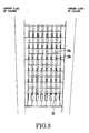
- Fig. 1 shows a cross sectional view of the gas outlet flue according to the present invention.
- Fig. 2 shows a cross section along the A-A line in Fig. 1.
- Fig. 3 shows a cross section along the B-B line in Fig. 1.
- Fig. 4 is a slant view of the gas outlet flue shown in Fig. 1.
- Fig. 5 shows a modification of the groove structure formed on the lower wall according to the present invention.
- Figs. 6, 7 and 8 show modifications of the groove structure.
- Fig. 9 shows the under-structure of the groove structure according to the present invention.
- Figs. 10 and 11 show further modifications of the groove structure according to the present invention.
- Fig. 12 is a cross sectional view showing the small path connecting between the vacancies in the lower wall and the exhaust port.
- Fig. 13 is a graph illustrating the advantages of the present invention.
- Fig. 14 schematically shows the scattering of the coke powder particles.
- Fig. 15 is a schematic view of the whole structure of a coke dry quenching equipment.
- Figs. 16 and 17 show a conventional gas outlet flue.
- Fig. 1 through 4 show an embodiment of the present gas outlet flue, wherein grooves are formed by arrangement of I-shape bricks on a
lower wall 19 constituting part of anexhaust port 8. In the drawings, same reference numerals are used to identify the same members in Fig. 16, and the reference numerals used in Figs. 15 and 16 will be used for convenience in the following description. - In the outlet flue of this embodiment, a
columnar wall 18 is disposed between anupper wall 17 and alower wall 19 so as to define anexhaust port 8 in the same way as in Fig. 16. A plurality ofcolumnar wall 18 are disposed in such a manner as to extend along the inner peripheral surface of the quenching tower 1 as shown in Fig. 15 and the spaces between thesecolumnar walls 18 serve as theexhaust ports 8. - A plurality of I-
shape bricks 25 are disposed on the inner surface of thelower wall 19 forming the lower surface of theexhaust ports 8 in the flowing direction of aninert gas stream 21 as shown in Fig. 2. - Therefore, on the inner wall side of the
lower wall 19, there is formed thegroove portion 23 comprisingvacancies 26a andnarrow paths 26b connecting between theexhaust port 8 and thevacancies 26a, thereby the coke powder particles accumulating near the upper end of thelower wall 19 of theexhaust port 8 drop through thenarrow paths 26b to thevacancies 26a and are conducted therefrom into thecooling chamber 4 so that the amount of the coke powder particles accumulating these portions decreases, thus minimizing the lowering of the vacancy ratio. - The
vacancies 26a of thegroove portion 23 contribute not only to lead out the coke powder particles but also to form a flow path through which the inert gas passes. As the result, the tendency of the inert gas to concentrate just below theupper wall 17 is restricted so that the amount of the coke lumps and coke powder particles blown off by the inert gas stream decreases. - As stated hereinbefore, since the vacancies of the groove portion formed in the
lower wall 19 ought to lead out the coke powder particles dropping therein into thecooling chamber 4 and form a flow path for theinert gas stream 21, the larger size of the vacancies is more preferable. - Also since the narrow paths ought to permit only the coke particles 31 accumulating near the top end of the lower wall to drop into the
vacancies 26a and to lead out the inert gas flowing through thevacancies 26a for convenience into theexhaust port 8, it is preferable the vacancies have a maximum size which prohibits the entrance of the coke lumps into the narrow paths. - Usually, the coke lumps 20 have an average particle size of about 50 to 60 mm in diameter, and it is optimum that the narrow paths have a size of 10 to 30 mm, preferably about 20 mm which prohibits the dropping of the coke lumps therethrough.
- In the case of the brick workings forming the groove portion, the
spaces 26b may be partially or totally eliminated by bringing the upper portions of the adjacent bricks into mutual contact as shown in Fig. 5. Thereby, although the efficiency of leading out the coke powder particles lowers, the bricks are fixed in all directions by the adjacent bricks so that a more stabilized brick structure can be obtained. - Further, instead of the I-
shape brick 25 as shown in Figs. 1 through 5, the shape of thevacancies 26a of thegroove portion 23 may be a base-shape as shown in Fig. 6, and thegroove portion 23 may be such as shown in Figs. 7 and 8, in which the vacancies and the narrow paths are integrated. With these structures, the advantages are that the shape of the bricks forming the groove portion is simpler as compared with the I-shape bricks, hence lowering the production cost of the bricks. - In Fig. 9, one example of the under-structure of the vacancies in the
groove portion 23 is shown. - Even when the groove portion is formed on the inside of the lower wall, the coke powder particles cannot be led out from the groove portion and the
groove portion 23 is clogged with the coke powder particles 31 if the under-structure is not appropriate. The groove portion thus cannot serve any more as the flow path for theinert gas stream 21 and, needless to say, it cannot lead out the coke powder particles. For this reason the under-structure of thegroove portion 23 is very important for the formation of the groove portion. - In Fig. 9 the angles ϑ₁ and ϑ₂ of the lower and upper inside surfaces of the groove portion are made larger than the repose angle of the coke and the angle ϑ₁ of the lower inside surface is made larger than the angle ϑ₂ of the circle formed by the lower end of the
ceiling wall 32 forming the groove portion is smaller than the diameter of the cooling chamber by the value of "a" as shown in Fig. 9 so as to reduce the amount of the coke lumps which come into thegroove portion 23 and reduce the resistance of the coke powder particles to the lead-out into thecooling chamber 4. - With the above structure, the coke powder particles 31 fallen in the
vacancies 26a of thegroove portion 23 can be smoothly into led into the cooling chamber without stagnating in thevacancies 26a. In this way thevacancies 26a of the groove portion are never clogged with the coke powder particles and part of theinert gas stream 21 rising upward from below the coolingchamber 4 can smoothly pass through thegroove portion 23. - In Figs. 10 and 11, modifications of the gas outlet flue of the present invention are shown, in which the
narrow paths 26b connecting between theexhaust port 8 and thevacancies 26a are arranged vertically relative to the direction of theinert gas stream 21 as shown in Fig. 12. - In these modifications, when the coke powder particles 31 accumulating near the
lower wall 19 fall down along the sloping wall of thelower wall 19, a greater amount of the coke powder particles 31 can drop from thenarrow paths 26b into thevacancies 26a. Therefor it is possible to lead out a more amount of the coke powder particles accumlating near thelower wall 19 into the cooling chamber and suppress the lowering of the vacancy ratio. - Fig. 13 is a flow rate distribution diagram of the
inert gas stream 21 passing through theexhaust port 8 when the lower surface of theexhaust port 8 is defined by thelower wall 19 provided on its slope surface with thegroove portion 23 havingvacancies 26a 50 mm in width and 100 mm in depth andnarrow paths 26b of 20 mm in width, which extends in the direction of theinert gas stream 21. As can be seen clearly from Fig. 13, the lowering of the vacancy ratio near the top end of thelower wall 19 is suppressed and since theinert gas stream 21 flows preferentially through thevacancies 26a defined between thelower wall 19 and the coke lumps 20, the flow rate of theinert gas stream 21 flowing along theupper wall 17 decreases and the flow rate distribution becomes uniform with respect to the cross-section of theexhaust port 8. Accordingly, the coke lumps 20 are not carried away by theinert gas stream 21 near theupper wall 17. - In contrast, with the
conventional exhaust port 8 explained with reference to Fig. 16, as the pressure loss is irregular across the cross-section of theexhaust port 8 due to the lowered vacancy ratio near the top end of thelower wall 19 the gas flow rate becomes extremely great on the side of theupper wall 17 represented by the dashed line, and the coke lumps 20 are carried away by theinert gas stream 21 at this portion where the flow rate is great or in other words, near theupper wall 17 to the exterior of the tower. - As described above, in accordance with the present invention, the groove portion is formed on the lower wall forming the lower surface of the exhaust ports: the vacancies are defined between the coke lumps entering the inlet side of the exhaust ports and the lower wall and the narrow paths connecting the vacancies and the exhaust port are formed. The groove portion functions to conduct the coke powder particles, accumulating on the slope portion of the lower wall, out of the exhaust port into the cooling chamber so as to suppress the lowering of the vacancy ratio in this portion, and functions as the path for the inert gas streams. As a result, the flow rate of the inert gas stream passing along the upper wall decreases, the inert gas does not concentrate locally on the portion immediately below the upper wall and does not flow there at a high speed and the accompanying with the gas flow of the coke lumps and the coke powder particles can be restricted. As a result, the trouble resulting from those coke lumps and coke powder particles which are carried out from the cooling chamber can be avoided and a stable operation can be carried out even when the supply of the inert gas is increased for an increased capacity of the coke dry quenching equipment.
Claims (3)
- A quenching tower gas outlet flue in a coke dry quenching equipment, comprising an exhaust port for connecting between a cooling chamber in a quenching tower and a ring duct disposed around said tower, said port being partitioned by a lower wall, an upper wall and a columnar wall of said quenching tower, and a plurality of grooves extending in a flow path direction of an inert gas stream passing through said exhaust port, said grooves being formed at least on said lower wall serving as an inlet of said exhaust port.
- A quenching tower gas outlet flue in a coke dry quenching equipment, comprising an exhaust port for connecting between a cooling chamber in a quenching tower and a ring duct disposed around said tower, said port being partitioned by a lower wall, an upper wall, and a columnar wall of said quenching tower, and a plurality of bricks of I-shape disposed side by side at least on said lower wall serving as an inlet portion of said port to form a plurality of grooves extending in a flow direction of an inert gas stream passing through said port.
- A quenching tower gas outlet flue in a coke dry quenching equipment, comprising an exhaust port for connecting between a cooling chamber in a quenching tower and a ring duct disposed around said tower, said port being partitioned by a lower wall, an upper wall and a columnar wall of said quenching tower, and a plurality of vacancies at least in said lower tower wall serving as an inlet of said port, said plurality of vacancies extending in a flow direction of an inert gas stream passing through said port and communicating to said exhaust port via a narrow path.
Applications Claiming Priority (2)
| Application Number | Priority Date | Filing Date | Title |
|---|---|---|---|
| JP2005152A JPH0756025B2 (en) | 1989-01-24 | 1990-01-12 | Coke dry fire extinguisher cooling tower gas outlet flue |
| JP5152/90 | 1990-01-12 |
Publications (2)
| Publication Number | Publication Date |
|---|---|
| EP0437265A1 EP0437265A1 (en) | 1991-07-17 |
| EP0437265B1 true EP0437265B1 (en) | 1994-04-06 |
Family
ID=11603299
Family Applications (1)
| Application Number | Title | Priority Date | Filing Date |
|---|---|---|---|
| EP91100272A Expired - Lifetime EP0437265B1 (en) | 1990-01-12 | 1991-01-10 | Quenching tower gas outlet flue of coke dry quenching equipment |
Country Status (4)
| Country | Link |
|---|---|
| EP (1) | EP0437265B1 (en) |
| KR (1) | KR0143242B1 (en) |
| DE (1) | DE69101559T2 (en) |
| ES (1) | ES2051032T3 (en) |
Families Citing this family (2)
| Publication number | Priority date | Publication date | Assignee | Title |
|---|---|---|---|---|
| DE19755100C2 (en) * | 1997-12-11 | 2003-10-02 | Rag Ag | Improved coke dry cooling shaft and its use to improve the flow behavior in coke dry cooling systems |
| US20110089163A1 (en) * | 2008-06-02 | 2011-04-21 | New Nature Co., Ltd. | Activated-steam-generating apparatus |
Family Cites Families (3)
| Publication number | Priority date | Publication date | Assignee | Title |
|---|---|---|---|---|
| DE1091080B (en) * | 1954-10-23 | 1960-10-20 | Steinmueller Gmbh L & C | Device for dry coke cooling |
| US3795987A (en) * | 1972-08-09 | 1974-03-12 | R Kemmetmueller | Cooling or preheating device for coarse or bulky material with heat space recovery equipment |
| DE2952065C2 (en) * | 1979-12-22 | 1984-10-11 | Carl Still Gmbh & Co Kg, 4350 Recklinghausen | Process for dry cooling of coke and coke cooling device for carrying out the process |
-
1991
- 1991-01-10 KR KR1019910000239A patent/KR0143242B1/en not_active Expired - Fee Related
- 1991-01-10 EP EP91100272A patent/EP0437265B1/en not_active Expired - Lifetime
- 1991-01-10 ES ES91100272T patent/ES2051032T3/en not_active Expired - Lifetime
- 1991-01-10 DE DE69101559T patent/DE69101559T2/en not_active Expired - Fee Related
Also Published As
| Publication number | Publication date |
|---|---|
| ES2051032T3 (en) | 1994-06-01 |
| EP0437265A1 (en) | 1991-07-17 |
| KR910014490A (en) | 1991-08-31 |
| DE69101559T2 (en) | 1994-10-06 |
| KR0143242B1 (en) | 1998-07-01 |
| DE69101559D1 (en) | 1994-05-11 |
Similar Documents
| Publication | Publication Date | Title |
|---|---|---|
| CA2521651C (en) | A method of and an apparatus for recovering heat in a fluidized bed reactor | |
| US5634516A (en) | Method and apparatus for treating or utilizing a hot gas flow | |
| GB2061758A (en) | Radiation boiler | |
| EP0390776B1 (en) | Method and reactor for combustion in a fluidised bed | |
| US5391357A (en) | Circulating fluidized bed reactor | |
| EP0094098A1 (en) | High temperature cyclone separator for gasification system | |
| WO1990005020A1 (en) | A circulating fluidized bed reactor | |
| KR20100125345A (en) | Device for producing synthesis gas with a gasification reactor and connecting quenching chamber | |
| US7287477B2 (en) | Cyclone bypass for a circulating fluidized bed reactor | |
| CN212805617U (en) | Wall of material returning heat exchanger, material returning heat exchanger and circulating fluidized bed boiler | |
| US4671806A (en) | Process and apparatus for cooling and purifying a hot gas containing slag particles | |
| EP0437265A1 (en) | Quenching tower gas outlet flue of coke dry quenching equipment | |
| US4123850A (en) | Apparatus for pyroprocessing and cooling particles | |
| CN1088480A (en) | Method and apparatus for operating a circulating fluidized bed reaction system | |
| JPH0139039B2 (en) | ||
| JP4137676B2 (en) | Coke dry fire extinguishing equipment gas outlet flue structure | |
| US2166199A (en) | Furnace construction and operation | |
| JPH0388890A (en) | Cooling tower gas outlet flue in coke dry quencher | |
| EP0082802B1 (en) | Calcining apparatus for powdery materials | |
| RU2099151C1 (en) | Centrifugal separator and method of separation of particles from hot gas flow carrying solid particles | |
| CN118142259B (en) | Multi-cyclone brick integrated structure separation system | |
| JPH0768524B2 (en) | Coke dry fire extinguisher cooling tower gas outlet flue | |
| JPH0745555Y2 (en) | Coke dry fire extinguisher cooling tower gas outlet flue | |
| EP0539416A1 (en) | Method and apparatus for treating gases and/or solid material in a circulating fluidized bed reactor | |
| RU2072893C1 (en) | Method and device for transferring solid particles |
Legal Events
| Date | Code | Title | Description |
|---|---|---|---|
| PUAI | Public reference made under article 153(3) epc to a published international application that has entered the european phase |
Free format text: ORIGINAL CODE: 0009012 |
|
| AK | Designated contracting states |
Kind code of ref document: A1 Designated state(s): DE ES FR GB IT NL |
|
| 17P | Request for examination filed |
Effective date: 19910925 |
|
| 17Q | First examination report despatched |
Effective date: 19930412 |
|
| GRAA | (expected) grant |
Free format text: ORIGINAL CODE: 0009210 |
|
| AK | Designated contracting states |
Kind code of ref document: B1 Designated state(s): DE ES FR GB IT NL |
|
| REF | Corresponds to: |
Ref document number: 69101559 Country of ref document: DE Date of ref document: 19940511 |
|
| ITF | It: translation for a ep patent filed | ||
| REG | Reference to a national code |
Ref country code: ES Ref legal event code: FG2A Ref document number: 2051032 Country of ref document: ES Kind code of ref document: T3 |
|
| ET | Fr: translation filed | ||
| PLBE | No opposition filed within time limit |
Free format text: ORIGINAL CODE: 0009261 |
|
| STAA | Information on the status of an ep patent application or granted ep patent |
Free format text: STATUS: NO OPPOSITION FILED WITHIN TIME LIMIT |
|
| 26N | No opposition filed | ||
| PGFP | Annual fee paid to national office [announced via postgrant information from national office to epo] |
Ref country code: FR Payment date: 19990111 Year of fee payment: 9 |
|
| PGFP | Annual fee paid to national office [announced via postgrant information from national office to epo] |
Ref country code: GB Payment date: 19990114 Year of fee payment: 9 |
|
| PGFP | Annual fee paid to national office [announced via postgrant information from national office to epo] |
Ref country code: DE Payment date: 19990115 Year of fee payment: 9 |
|
| PGFP | Annual fee paid to national office [announced via postgrant information from national office to epo] |
Ref country code: ES Payment date: 19990125 Year of fee payment: 9 |
|
| PGFP | Annual fee paid to national office [announced via postgrant information from national office to epo] |
Ref country code: NL Payment date: 19990131 Year of fee payment: 9 |
|
| PG25 | Lapsed in a contracting state [announced via postgrant information from national office to epo] |
Ref country code: GB Free format text: LAPSE BECAUSE OF NON-PAYMENT OF DUE FEES Effective date: 20000110 |
|
| PG25 | Lapsed in a contracting state [announced via postgrant information from national office to epo] |
Ref country code: ES Free format text: LAPSE BECAUSE OF NON-PAYMENT OF DUE FEES Effective date: 20000111 |
|
| PG25 | Lapsed in a contracting state [announced via postgrant information from national office to epo] |
Ref country code: NL Free format text: LAPSE BECAUSE OF NON-PAYMENT OF DUE FEES Effective date: 20000801 |
|
| GBPC | Gb: european patent ceased through non-payment of renewal fee |
Effective date: 20000110 |
|
| PG25 | Lapsed in a contracting state [announced via postgrant information from national office to epo] |
Ref country code: FR Free format text: LAPSE BECAUSE OF NON-PAYMENT OF DUE FEES Effective date: 20000929 |
|
| NLV4 | Nl: lapsed or anulled due to non-payment of the annual fee |
Effective date: 20000801 |
|
| PG25 | Lapsed in a contracting state [announced via postgrant information from national office to epo] |
Ref country code: DE Free format text: LAPSE BECAUSE OF NON-PAYMENT OF DUE FEES Effective date: 20001101 |
|
| REG | Reference to a national code |
Ref country code: FR Ref legal event code: ST |
|
| REG | Reference to a national code |
Ref country code: ES Ref legal event code: FD2A Effective date: 20010910 |
|
| PG25 | Lapsed in a contracting state [announced via postgrant information from national office to epo] |
Ref country code: IT Free format text: LAPSE BECAUSE OF NON-PAYMENT OF DUE FEES;WARNING: LAPSES OF ITALIAN PATENTS WITH EFFECTIVE DATE BEFORE 2007 MAY HAVE OCCURRED AT ANY TIME BEFORE 2007. THE CORRECT EFFECTIVE DATE MAY BE DIFFERENT FROM THE ONE RECORDED. Effective date: 20050110 |