EP0436787A2 - Fluidized bed apparatus for the production and/or post-treatment of pourable material - Google Patents
Fluidized bed apparatus for the production and/or post-treatment of pourable material Download PDFInfo
- Publication number
- EP0436787A2 EP0436787A2 EP90120199A EP90120199A EP0436787A2 EP 0436787 A2 EP0436787 A2 EP 0436787A2 EP 90120199 A EP90120199 A EP 90120199A EP 90120199 A EP90120199 A EP 90120199A EP 0436787 A2 EP0436787 A2 EP 0436787A2
- Authority
- EP
- European Patent Office
- Prior art keywords
- lance
- fluid bed
- bed apparatus
- trough
- gas flow
- Prior art date
- Legal status (The legal status is an assumption and is not a legal conclusion. Google has not performed a legal analysis and makes no representation as to the accuracy of the status listed.)
- Granted
Links
Images


Classifications
-
- B—PERFORMING OPERATIONS; TRANSPORTING
- B01—PHYSICAL OR CHEMICAL PROCESSES OR APPARATUS IN GENERAL
- B01J—CHEMICAL OR PHYSICAL PROCESSES, e.g. CATALYSIS OR COLLOID CHEMISTRY; THEIR RELEVANT APPARATUS
- B01J8/00—Chemical or physical processes in general, conducted in the presence of fluids and solid particles; Apparatus for such processes
- B01J8/18—Chemical or physical processes in general, conducted in the presence of fluids and solid particles; Apparatus for such processes with fluidised particles
- B01J8/24—Chemical or physical processes in general, conducted in the presence of fluids and solid particles; Apparatus for such processes with fluidised particles according to "fluidised-bed" technique
- B01J8/38—Chemical or physical processes in general, conducted in the presence of fluids and solid particles; Apparatus for such processes with fluidised particles according to "fluidised-bed" technique with fluidised bed containing a rotatable device or being subject to rotation or to a circulatory movement, i.e. leaving a vessel and subsequently re-entering it
- B01J8/384—Chemical or physical processes in general, conducted in the presence of fluids and solid particles; Apparatus for such processes with fluidised particles according to "fluidised-bed" technique with fluidised bed containing a rotatable device or being subject to rotation or to a circulatory movement, i.e. leaving a vessel and subsequently re-entering it being subject to a circulatory movement only
- B01J8/386—Chemical or physical processes in general, conducted in the presence of fluids and solid particles; Apparatus for such processes with fluidised particles according to "fluidised-bed" technique with fluidised bed containing a rotatable device or being subject to rotation or to a circulatory movement, i.e. leaving a vessel and subsequently re-entering it being subject to a circulatory movement only internally, i.e. the particles rotate within the vessel
-
- B—PERFORMING OPERATIONS; TRANSPORTING
- B01—PHYSICAL OR CHEMICAL PROCESSES OR APPARATUS IN GENERAL
- B01J—CHEMICAL OR PHYSICAL PROCESSES, e.g. CATALYSIS OR COLLOID CHEMISTRY; THEIR RELEVANT APPARATUS
- B01J2/00—Processes or devices for granulating materials, e.g. fertilisers in general; Rendering particulate materials free flowing in general, e.g. making them hydrophobic
- B01J2/16—Processes or devices for granulating materials, e.g. fertilisers in general; Rendering particulate materials free flowing in general, e.g. making them hydrophobic by suspending the powder material in a gas, e.g. in fluidised beds or as a falling curtain
-
- B—PERFORMING OPERATIONS; TRANSPORTING
- B01—PHYSICAL OR CHEMICAL PROCESSES OR APPARATUS IN GENERAL
- B01J—CHEMICAL OR PHYSICAL PROCESSES, e.g. CATALYSIS OR COLLOID CHEMISTRY; THEIR RELEVANT APPARATUS
- B01J8/00—Chemical or physical processes in general, conducted in the presence of fluids and solid particles; Apparatus for such processes
- B01J8/0015—Feeding of the particles in the reactor; Evacuation of the particles out of the reactor
-
- B—PERFORMING OPERATIONS; TRANSPORTING
- B01—PHYSICAL OR CHEMICAL PROCESSES OR APPARATUS IN GENERAL
- B01J—CHEMICAL OR PHYSICAL PROCESSES, e.g. CATALYSIS OR COLLOID CHEMISTRY; THEIR RELEVANT APPARATUS
- B01J8/00—Chemical or physical processes in general, conducted in the presence of fluids and solid particles; Apparatus for such processes
- B01J8/18—Chemical or physical processes in general, conducted in the presence of fluids and solid particles; Apparatus for such processes with fluidised particles
- B01J8/1818—Feeding of the fluidising gas
Definitions
- the process chamber is the circular interior of a container which is rotationally symmetrical with respect to a vertical axis.
- the process chamber contains a ring of guide vanes which, viewed in the direction of the container axis, overlap one another and impart a swirl to the upward gas flow.
- lances each having a plurality of material discharge nozzles arranged in the flow direction of the gas. These nozzles can be used to spray large amounts of powdery and / or liquid substance per unit of time into a fluidized bed formed above the guide vanes.
- Granular material which has been produced and / or further processed in this known fluid bed apparatus is distinguished by a particularly high degree of homogeneity. For example, a narrow range of grain sizes can be achieved in the manufacture of build-up granules, and coating processes result in coating coatings of particularly uniform thickness.
- pellets with varnish coatings of different composition or thickness are occasionally required so that certain active substances are released in specific areas of the human gastrointestinal tract.
- such different pellets had to be produced in batches in the known apparatus one after the other, with longer interruptions in operation for the conversion of the apparatus to different operating conditions being inevitable.
- the batch size can only be varied within relatively narrow limits, so that production with such a fluid bed apparatus cannot readily be adapted to different operational requirements.
- the invention is therefore based on the object of designing a fluidized bed apparatus for producing and / or further treating pourable goods from solid moldings in such a way that that it can be easily adapted to different requirements of the type described.
- a trough according to the invention of a given total length can form a single straight-line treatment section in a correspondingly elongated housing or can be divided into several sections which can be arranged next to one another in a space-saving manner in a common housing.
- the same or different treatment steps can be carried out simultaneously in more or less long sections of the trough and sections that are not required can be shut down, for example by inserting partitions.
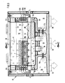
- the fluidized bed apparatus shown in FIGS. 1 to 4 has a housing 10 which forms an oblong cuboid in the horizontal direction and has heat-insulated walls.
- Six process chambers 12 are formed within the housing 10, each having a common base 14, two gas inlets 16 arranged in the base as well as gas outlets 18, five of which are each assigned to two adjacent process chambers 12.
- the gas inlets 16 connect the process chambers 12 to a common supply air chamber 20 which is arranged under the base 14 and which is to be supplied with dehumidified warm air or another process gas via connections 22.
- the gas outlets 18 open into exhaust air chambers 24, which are arranged on the long sides of the housing 10 and extend to below the base 14, where they pass through connections 26 can be connected to the suction side of a conventional blower.
- each of the process chambers 12 is closed during operation with a cover 28, which is made of glass, for example, and can be swung up for cleaning purposes.
- a gas-permeable conveyor belt 30 extends through the entire housing 10 in the longitudinal direction thereof, for example a known link belt made of metal or plastic wire helices.
- the conveyor belt 30 can be pulled off a decoiler 32 and can be wound up on a decoiler 34 after use. Instead of these two reels 32 and 34, deflection rollers can be provided, which are wrapped around by an endless conveyor belt.
- the end faces at which the conveyor belt 30 enters and exits the housing 10 are normally closed by a flap 36.
- a film 38 is placed on a section of the conveyor belt 30 that is somewhat longer than the housing 10, which film is then brought into the housing 10 by moving the conveyor belt 30, with one in the process chambers 12 Loaded manufactured or treated goods and is moved out of the housing 10 together with this by moving the conveyor belt 30 again. As indicated in FIG. 1, the film 38 is pulled upwards so far at the lateral boundaries of the process chambers 12 that contamination of the conveyor belt 30 with the manufactured and / or treated material is prevented.
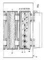
- a lance 40 extends horizontally through each process chamber 12 at a distance above the floor 14.
- Each of the lances 40 has a teardrop-shaped profile which is symmetrical to the central plane A and is rounded at the bottom and pointed at the top.
- two guide vanes 42 and 44 are arranged parallel to the associated lance 40.
- each lance 40 The two guide vanes 42 and 44 on one and the other side of each lance 40 are connected to one another by plates 46 which each extend in a vertical longitudinal plane and are fastened on a shaft 48 arranged parallel to the lance 40.
- the shafts 48 are each connected to a swivel drive 50, for example with a hydraulic or pneumatic rotary vane motor, with which the associated guide vanes 42 and 44 can be pivoted back and forth in an angular range of, for example, 30 °.
- a half-shell 52 is arranged on each side of each lance 40, also parallel to it.
- the half shells 52 together with the associated guide vanes 42 and 44 and the lance 40 form a trough 53 which, in the operating position of the guide vanes - sh. in Fig. 2, the second and third process chamber 12 from the right - is almost closed at the bottom, but leaves three gaps B, C and D on both sides of the lance 40, which extend over the entire width of the process chamber 12.
- Process air in the form of a general gas flow E can flow upward through the column B, C and D around the profile of the lance 40 and a fluidized bed delimited by the trough 53, starting from the associated gas inlets 16 Form F (see FIG. 2 the second chamber from the right and FIG. 3).
- the guide vanes 42 and 44 can be moved from the operating position into an emptying position by means of the swivel drive 50 - see FIG. in Fig. 2, the first chamber from the right - swivel, in which the material that has collected in the trough 53 after the air flow has stopped can trickle down through the gaps B, C and D onto the film 38.
- the upper edges of the half-shells 52 in adjacent process chambers 12 leave a space between them which is covered by a concave cover profile 54 seen from below. Between the upper edge of each half-shell 52 and the associated cover profile 54, a gap D 'remains free, through which a further part of the general gas flow E flows from top to bottom into the relevant trough 53.
- the cover profiles 54 are arranged so that the material can flow over them when it exceeds a certain height in one of the troughs 53. Alternatively, adjacent troughs 53 can be separated from one another by an intermediate wall 56.
- the gas outlets 18 arranged further up are covered by baffle plates 58 in such a way that at most dust-like particles of the material get into the exhaust air chambers 24, where they can be filtered out of the gas stream in the usual way.
- the apparatus shown in FIGS. 1 to 4 is equipped in all of its process chambers 12 for painting and drying prefabricated moldings P, for example pellets or tablets, which are poured into each individual trough 53 from above, in a fluidized state. 5 to 9, on the other hand, there is the possibility of first extruding particles from doughy mass, then painting them and finally drying them. Since the area of application of the apparatus shown in FIGS. 5 to 9 thus begins at an earlier stage of the manufacturing process, details of this apparatus are described below before further similarities between the two apparatuses are discussed.
- prefabricated moldings P for example pellets or tablets
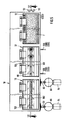
- FIGS. 5 to 7 three elongate process chambers 12, which correspond to those shown in FIGS. 1 to 4, are arranged one behind the other in the housing 12. Of these three process chambers 12, the left one in FIGS. 5 and 6 is used for extrusion, the middle one for painting and the right one for drying.
- a single lance 40 extends through these three process chambers 12 and is divided into three aligned sections, one for each process chamber 12. All sections of the lance 40 have the outer profile shown in FIG. 7 over their entire length, but only the section in the left process chamber 12 is designed in all details as shown in FIGS. 8 and 9 and described below .
- the section of the lance 40 in the first process chamber 12 on the left in FIGS. 5 and 6 has a longitudinally extending conveying channel 60 of circular cross-section, which is arranged coaxially with the likewise circular-arc-shaped lower part of the lance profile and extends approximately over the entire length of the first Process chamber 12 extends.
- a pump 62 for example a commercially available eccentric screw pump, which is driven by an electric motor 64 and presses a doughy mass to be extruded from a container 66 into the delivery channel 60, is laterally connected to the two ends of the delivery channel 60.
- the section of the lance 40 arranged in the first process chamber 12 contains in its conveying channel 60 a stirrer 68 which can be driven by its own electric motor 69 and ensures that the mass in the conveying channel 60 is constantly stirred and does not solidify.
- the delivery channel 60 is connected by a longitudinal slot 70 to a distribution channel 72, which also extends in the longitudinal direction of the lance 40, and from which holes are inclined at regular intervals lead up to the surface of the lance 40.
- the holes each have a shoulder on which they widen outwards and on which there is a sealing ring.
- a material discharge nozzle 80 designed as an extrusion nozzle is inserted up to the shoulder.
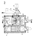
- Each of the stock dispensing nozzles 80 which are located in the first process chamber 12 and shown in FIGS. 8 and 9, have an axially inner narrower region which determines the diameter of a strand of doughy mass formed in the stock dispensing nozzle 80 and an axially outer enlarged region 84, which can be ventilated from the outside through at least one opening 86 in order to promote the drying of the strand.
- an opening 86 is provided as an opening 86, which is arranged on the windward side of the material delivery nozzle 80 with respect to the general gas flow E and extends from the beginning of the enlarged area 84 to the free end of the material delivery nozzle 80.
- the section of the lance 40 arranged in the first process chamber 12 also contains two lower compressed gas channels 94 parallel to the delivery channel 60, from which pressurized gas nozzles 96 extend in such a way that a pressurized gas nozzle 96 is directed onto the or an opening 86 of each material discharge nozzle 80.
- the compressed gas channels 94 are intermittently supplied with compressed air, which can be dried and preheated, via electromagnetic valves of a known type.
- the lower compressed gas nozzles 96 discharge compressed air intermittently onto the mouth area of the associated substance discharge nozzle 80.
- the compressed air intermittently acts on the strand in a sharply bundled jet through the or a breakthrough in the associated material discharge nozzle 80, so that an extrudate particle H breaks off from it each time the compressed air blows.
- a further compressed gas channel 98 is arranged, likewise parallel to the delivery channel 60, which is continuously supplied with warm, dry compressed air.
- Compressed gas nozzles 100 emanate from the upper compressed gas channel 98 and are directed from above at an acute angle towards the respective mouth area of a material discharge nozzle 80.
- the extrudate particle H formed therein is thus dried by a hot air jet and prevented by its pressure from breaking off prematurely before its free end has reached the end of the shield 88.
- the broken-off extrudate particles H are carried upward in the first process chamber 12 by the general gas stream E, a fluidized bed F or fluidized bed forming in the trough 53 formed by the half-shells 52 and guide vanes 42 and 44, in which the extrudate particles H are further dried.
- This fluidized bed F moves slowly but steadily forward on both sides of the lance 40 5 and 6 to the right, since the partial flows of the general gas flow E, which pass through the columns B, C and D, have a forward flow component.
- This flow component arises from the fact that the guide vanes 42 and 44 and beads or ribs 102 projecting upwards into the half-shells 52, which rise to the left on both sides of the lance 40 and thus form a herringbone pattern with the direction of the arrow to the right in the plan view according to FIG. 5.
- the guide vanes 42 and 44 and the half-shells 52 have the same shape and the same herringbone pattern as in the first process chamber 12.
- the section of the lance 40 which extends through the middle process chamber 12 extends, is only designed for spraying the extrudate particles H and for this purpose equipped with dispensing nozzles 80 in the form of multi-component nozzles. These dispensing nozzles 80 are each arranged in a depression 104 at the upper edge of the lance profile and directed vertically upwards in the central plane A.
- the associated middle section of the lance 40 is connected to a liquid line 106, a moist air line 108 and a dry air line 110.
- the material delivery nozzles 80 fed by these lines generate a paint mist, e.g. from an aqueous or organic solution, suspension or dispersion, so that the extrudate particles H which are constantly moving forward in the fluidized bed F are coated.
- a paint mist e.g. from an aqueous or organic solution, suspension or dispersion
- Suitable multi-component nozzles are known from DE 3806537 A1, especially FIGS. 5 to 7.
- the lacquered extrudate particles H are only dried while they continue to move forward.
- the fluidized bed F that of the general one, can suffice for drying Gas flow E is generated in the trough 53.
- the lance 40 can also be equipped with nozzles in the third process chamber 12, through which, for example, additional warm air is introduced into the fluidized bed F in order to promote drying.
- the lacquered and dried extrudate particles H fall into a discharge chute 112.
- the process chambers 12 are easily accessible for cleaning when the lids 28 are folded up.
- the apparatus shown in Fig. 1 to 4 works in batches.
- the lances 40 in all process chambers 12 are equipped with material discharge nozzles 80 in the form of multi-substance nozzles of the type known from DE 3806537 A1. According to FIG. 3, they are connected at their two ends to a liquid line 106, a moist air line 108 and a dry air line 110.
- the guide vanes 42 and 44 and / or the half-shells 52 in turn have inclined beads or ribs 102 which, however, viewed from above, have the same inclination on both sides of the lance 40.
- Such ribs 102 give the general gas flow E an oblique direction, so that the fluidized bed F on both sides of the lance 40 travels in opposite directions along the lance and the extrudate particles H are consequently mixed particularly well.
Abstract
Description
Die Erfindung betrifft eine Fließbettapparatur zum Herstellen und/oder Weiterbehandeln schüttfähigen Gutes aus festen Formlingen, mit
- mindestens einer Prozeßkammer, die mindestens einen Gaseinlaß und mindestens einen Gasauslaß zum Erzeugen eines allgemeinen Gasstroms aufweist,
- mindestens einer hohlen Lanze, die sich in der Prozeßkammer quer zum allgemeinen Gasstrom erstreckt, ein zu einer Mittelebene symmetrisches Profil hat und einen in ihrer Längsrichtung verlaufenden Förderkanal enthält, an den Stoffabgabedüsen angeschlossen sind, und
- mindestens einem Paar Leitflügel, zwischen denen die Lanze angeordnet und von unten nach oben vom allgemeinen Gasstrom umströmt ist.
- at least one process chamber which has at least one gas inlet and at least one gas outlet for generating a general gas flow,
- at least one hollow lance which extends transversely to the general gas flow in the process chamber, has a profile symmetrical with respect to a central plane and contains a conveying duct running in its longitudinal direction, to which material discharge nozzles are connected, and
- at least one pair of guide vanes, between which the lance is arranged and the general gas flow flows from bottom to top.
Bei einer aus der DE 3839723 C1 bekannten Fließbettapparatur dieser Gattung ist die Prozeßkammer der kreisringförmige Innenraum eines Behälters, der in bezug auf eine senkrechte Achse rotationssymmetrisch ist. Die Prozeßkammer enthält einen Kranz Leitflügel, die, in Richtung der Behälterachse betrachtet, einander überlappen, und dem aufwärtsgerichteten Gasstrom einen Drall erteilen. Zwischen den Leitflügeln sind radial zur Behälterachse Lanzen angeordnet, die je mehrere in Strömungsrichtung des Gases angeordnete Stoffabgabedüsen aufweisen. Durch diese Düsen können große Mengen pulverförmiger und/oder flüssiger Substanz je Zeiteinheit in ein oberhalb der Leitflügel sich bildendes Fließbett eingesprüht werden.In a fluidized bed apparatus of this type known from DE 3839723 C1, the process chamber is the circular interior of a container which is rotationally symmetrical with respect to a vertical axis. The process chamber contains a ring of guide vanes which, viewed in the direction of the container axis, overlap one another and impart a swirl to the upward gas flow. Between the guide vanes are arranged radially to the container axis, lances each having a plurality of material discharge nozzles arranged in the flow direction of the gas. These nozzles can be used to spray large amounts of powdery and / or liquid substance per unit of time into a fluidized bed formed above the guide vanes.
Granulatförmiges Gut, das in dieser bekannten Fließbettapparatur hergestellt und/oder weiterbearbeitet worden ist, zeichnet sich durch besonders große Homogenität aus. Beispielsweise läßt sich beim Herstellen von Aufbaugranulaten ein enges Korngrößenspektrum erzielen und beim Coaten ergeben sich Lacküberzüge von besonders gleichmäßiger Dicke.Granular material which has been produced and / or further processed in this known fluid bed apparatus is distinguished by a particularly high degree of homogeneity. For example, a narrow range of grain sizes can be achieved in the manufacture of build-up granules, and coating processes result in coating coatings of particularly uniform thickness.
Solche Gleichmäßigkeit ist jedoch nicht in jedem Fall erwünscht. Beispielsweise werden zum Füllen von Kapseln für pharmazeutische Anwendungen gelegentlich Pellets mit unterschiedlich zusammengesetzten oder verschieden dicken Lacküberzügen benötigt, damit bestimmte Wirkstoffe gezielt in bestimmten Bereichen des menschlichen Magen-Darmtraktes freigesetzt werden. Solche unterschiedlichen Pellets mußten bisher in der bekannten Apparatur chargenweise nacheinander hergestellt werden, wobei längere Betriebsunterbrechungen für das Umstellen der Apparatur auf unterschiedliche Betriebsbedingungen unvermeidlich waren. Bei gegebener Behältergröße der bekannten Apparatur läßt sich die Chargengröße nur in verhältnismäßig engen Grenzen variieren, so daß die Produktion mit einer solchen Fließbettapparatur nicht ohne weiteres an unterschiedliche betriebliche Erfordernisse angepaßt werden kann.However, such uniformity is not always desirable. For example, to fill capsules for pharmaceutical applications, pellets with varnish coatings of different composition or thickness are occasionally required so that certain active substances are released in specific areas of the human gastrointestinal tract. Until now, such different pellets had to be produced in batches in the known apparatus one after the other, with longer interruptions in operation for the conversion of the apparatus to different operating conditions being inevitable. For a given container size of the known apparatus, the batch size can only be varied within relatively narrow limits, so that production with such a fluid bed apparatus cannot readily be adapted to different operational requirements.
Der Erfindung liegt deshalb die Aufgabe zugrunde, eine Fließbettapparatur zum Herstellen und/oder weiterbehandeln schüttfähigen Gutes aus festen Formlingen derart zu gestalten, daß sie sich auf einfache Weise an unterschiedliche Anforderungen der beschriebenen Art anpassen läßt.The invention is therefore based on the object of designing a fluidized bed apparatus for producing and / or further treating pourable goods from solid moldings in such a way that that it can be easily adapted to different requirements of the type described.
Die Aufgabe ist erfindungsgemäß ausgehend von einer Fließbettapparatur der eingangs beschriebenen Gattung dadurch gelöst, daß
- die Mittelebene der Lanze mindestens annähernd senkrecht angeordnet ist,
- über den Leitflügeln ein Paar Halbschalen angeordnet ist, das zusammen mit den Leitflügeln einen geraden, zur Mittelebene mindestens annähernd symmetrischen Trog bildet, und
- zwischen Gaseinlaß und Gasauslaß ein Druckgefälle herstellbar ist, bei dem sich innerhalb des Troges ein geradliniges Fließbett bildet.
- the center plane of the lance is arranged at least approximately vertically,
- Arranged above the guide vanes is a pair of half-shells which, together with the guide vanes, form a straight trough which is at least approximately symmetrical with respect to the central plane, and
- a pressure gradient can be produced between the gas inlet and the gas outlet, in which a rectilinear fluid bed forms within the trough.
Ein erfindungsgemäßer Trog von gegebener Gesamtlänge kann eine einzige geradlinige Behandlungsstrecke in einem entsprechend langgestreckten Gehäuse bilden oder in mehrere Abschnitte unterteilt sein, die sich in einem gemeinsamen Gehäuse raumsparend nebeneinander anordnen lassen. In jedem Fall kann man entsprechend dem Bedarf in mehr oder weniger langen Abschnitten des Troges gleiche oder unterschiedliche Behandlungsschritte gleichzeitig ablaufen lassen und nicht benötigte Abschnitte stillegen, beispielsweise durch Einfügen von Zwischenwänden. Man kann auch unterschiedliche, beispielsweise nebeneinander angeordnete Abschnitte des Troges von vorneherein mit unterschiedlichen Ausgangsstoffen, beispielsweise Pellets, Kristalle, Granulate oder Tabletten unterschiedlicher Zusammensetzung und/oder Größe, beschicken, um schließlich ein Endprodukt mit einer bestimmten Mischung unterschiedlicher Teilchen zu erhalten.A trough according to the invention of a given total length can form a single straight-line treatment section in a correspondingly elongated housing or can be divided into several sections which can be arranged next to one another in a space-saving manner in a common housing. In any case, the same or different treatment steps can be carried out simultaneously in more or less long sections of the trough and sections that are not required can be shut down, for example by inserting partitions. It is also possible to feed different, for example adjacent, sections of the trough from the start with different starting materials, for example pellets, crystals, granules or tablets of different composition and / or size, in order finally to obtain an end product with a specific mixture of different particles.
Vorteilhafte Weiterbildungen der Erfindung ergeben sich aus den Unteransprüchen.Advantageous developments of the invention result from the subclaims.
Ausführungsbeispiele erfindungsgemäßer Fließbettapparaturen werden im folgenden anhand schematischer Zeichnungen mit weiteren Einzelheiten erläutert. Es zeigen:
- Fig. 1
- einen Längsschnitt in der senkrechten Ebene I-I in Fig. 3 durch eine Apparatur zum Lackieren und Trocknen vorgefertigter Formlinge,
- Fig. 2
- einen vergrößerten Ausschnitt aus Fig. 1,
- Fig. 3
- den senkrechten Querschnitt III-III in Fig. 1,
- Fig. 4
- die Draufsicht in Richtung des Pfeils IV in Fig. 1,
- Fig. 5
- die Draufsicht einer Apparatur zum Extrudieren, Lackieren und Trocknen von Formlingen,
- Fig. 6
- den Längsschnitt VI-VI in Fig. 5,
- Fig. 7
- den Querschnitt VII-VII in Fig. 5,
- Fig. 8
- einen stark vergrößerten Ausschnitt aus Fig. 7 und
- Fig. 9
- die zugehörige, teilweise als Schnitt IX-IX in Fig. 8 gezeichnete Seitenansicht.
- Fig. 1
- 3 shows a longitudinal section in the vertical plane II in FIG. 3 through an apparatus for painting and drying prefabricated moldings,
- Fig. 2
- 2 shows an enlarged detail from FIG. 1,
- Fig. 3
- the vertical cross section III-III in Fig. 1,
- Fig. 4
- the top view in the direction of arrow IV in Fig. 1,
- Fig. 5
- the top view of an apparatus for extruding, painting and drying moldings,
- Fig. 6
- the longitudinal section VI-VI in Fig. 5,
- Fig. 7
- the cross section VII-VII in Fig. 5,
- Fig. 8
- a greatly enlarged section of Fig. 7 and
- Fig. 9
- the associated side view, partly drawn as section IX-IX in FIG. 8.
Die in Fig. 1 bis 4 dargestellte Fließbettapparatur hat ein Gehäuse 10, das einen in waagerechter Richtung langgestreckten Quader bildet und wärmeisolierte Wände hat. Innerhalb des Gehäuses 10 sind sechs Prozeßkammern 12 ausgebildet, die einen gemeinsamen Boden 14, je zwei im Boden angeordnete Gaseinlässe 16 sowie Gasauslässe 18 aufweisen, von denen fünf je zwei benachbarten Prozeßkammern 12 gemeinsam zugeordnet sind.The fluidized bed apparatus shown in FIGS. 1 to 4 has a
Die Gaseinlässe 16 verbinden die Prozeßkammern 12 mit einer unter dem Boden 14 angeordneten gemeinsamen Zuluftkammer 20, die über Anschlüsse 22 mit entfeuchteter Warmluft oder einem anderen Prozeßgas zu versorgen ist. Die Gasauslässe 18 münden in Abluftkammern 24, die an den Längsseiten des Gehäuses 10 angeordnet sind und sich bis unter den Boden 14 erstrecken, wo sie über Anschlüsse 26 an die Saugseite eines üblichen Gebläses anschließbar sind. Nach oben hin ist jede der Prozeßkammern 12 im Betrieb mit einem Deckel 28 verschlossen, der beispielsweise aus Glas besteht und für Reinigungszwecke hochschwenkbar ist.The
Auf dem Boden 14 aufliegend erstreckt sich durch das gesamte Gehäuse 10 in dessen Längsrichtung ein gasdurchlässiges Förderband 30, beispielsweise ein bekanntes Gliederband aus Metall- oder Kunststoffdrahtwendeln. Das Förderband 30 läßt sich von einer Abwickelhaspel 32 abziehen und nach Gebrauch auf eine Aufwickelhaspel 34 aufwickeln. Anstelle dieser beiden Haspeln 32 und 34 können Umlenkrollen vorgesehen sein, die von einem endlosen Förderband umschlungen werden. Die Stirnseiten, an denen das Förderband 30 in das Gehäuse 10 ein- und aus ihm austritt, sind normalerweise mit je einer Klappe 36 verschlossen.Lying on the
Zum Entleeren der Prozeßkammern 12 ist vorgesehen, daß auf einen Abschnitt des Förderbandes 30, der etwas länger als das Gehäuse 10 ist, eine Folie 38 aufgelegt wird, die anschließend durch Bewegen des Förderbandes 30 in das Gehäuse 10 hineingebracht, mit einem in den Prozeßkammern 12 hergestellten oder behandelten Gut beladen und zusammen mit diesem durch erneutes Bewegen des Förderbandes 30 aus dem Gehäuse 10 herausgefahren wird. Die Folie 38 ist, wie in Fig. 1 angedeutet, an seitlichen Begrenzungen der Prozeßkammern 12 so weit nach oben gezogen, daß eine Kontamination des Förderbandes 30 mit dem hergestellten und/oder behandelten Gut verhindert wird.To empty the
Sämtliche Einbauten, die im folgenden beschrieben werden, sind symmetrisch in bezug auf eine senkrechte Mittelebene A der zugehörigen Prozeßkammer 12, die quer zur Längsrichtung des Gehäuses 10 angeordnet ist. In der Mittelebene A erstreckt sich waagerecht in einem Abstand über dem Boden 14 eine Lanze 40 durch jede Prozeßkammer 12 hindurch. Jede der Lanzen 40 hat ein zur Mittelebene A symmetrisches, tropfenförmiges Profil, das unten abgerundet und oben spitz ist. Auf beiden Seiten dieses Profils sind je zwei Leitflügel 42 und 44 parallel zur zugehörigen Lanze 40 angeordnet.All internals, which are described below, are symmetrical with respect to a vertical central plane A of the associated
Die beiden Leitflügel 42 und 44 auf der einen und der anderen Seite jeder Lanze 40 sind miteinander durch Platten 46 verbunden, die sich in je einer senkrechten Längsebene erstrecken und auf einer parallel zur Lanze 40 angeordneten Welle 48 befestigt sind. Die Wellen 48 sind mit je einem Schwenkantrieb 50 verbunden, beispielsweise mit einem hydraulischen oder pneumatischen Drehflügelmotor, mit dem die zugehörigen Leitflügel 42 und 44 in einem Winkelbereich von beispielsweise 30° hin- und herschwenkbar sind.The two
Beiderseits jeder Lanze 40, ebenfalls parallel zu ihr, ist je eine Halbschale 52 angeordnet. Die Halbschalen 52 bilden zusammen mit den zugehörigen Leitflügeln 42 und 44 und der Lanze 40 einen Trog 53, der in der Betriebsstellung der Leitflügel - sh. in Fig. 2 die zweite und dritte Prozeßkammer 12 von rechts - nach unten nahezu geschlossen ist, jedoch beiderseits der Lanze 40 je drei Spalte B, C und D freiläßt, die sich über die gesamte Breite der Prozeßkammer 12 erstrecken. Durch die Spalte B, C und D kann, ausgehend von den zugehörigen Gaseinlässen 16, Prozeßluft in Form eines allgemeinen Gasstromes E (sh. Fig. 2 und 3) um das Profil der Lanze 40 herum nach oben strömen und ein vom Trog 53 umgrenztes Fließbett F bilden (sh. in Fig. 2 die zweite Kammer von rechts und Fig. 3).A half-
Aus der Betriebsstellung lassen sich die Leitflügel 42 und 44 mittels des Schwenkantriebs 50 in eine Entleerungsstellung - sh. in Fig. 2 die erste Kammer von rechts - schwenken, in der das Gut, das sich nach dem Abstellen des Luftstroms im Trog 53 gesammelt hat, durch die Spalte B, C und D nach unten auf die Folie 38 rieseln kann.The guide vanes 42 and 44 can be moved from the operating position into an emptying position by means of the swivel drive 50 - see FIG. in Fig. 2, the first chamber from the right - swivel, in which the material that has collected in the
Die oberen Ränder der Halbschalen 52 in benachbarten Prozeßkammern 12 lassen zwischen sich einen Zwischenraum frei, der durch ein von unten her gesehen konkaves Deckprofil 54 überdeckt ist. Zwischen dem oberen Rand jeder Halbschale 52 und dem zugehörigen Deckprofil 54 bleibt ein Spalt D' frei, durch den ein weiterer Teil des allgemeinen Gasstroms E von oben nach unten in den betreffenden Trog 53 einströmt. Die Deckprofile 54 sind so angeordnet, daß das Gut über sie hinwegströmen kann, wenn es in einem der Tröge 53 eine bestimmte Höhe überschreitet. Alternativ können benachbarte Tröge 53 durch eine Zwischenwand 56 voneinander getrennt sein. Die weiter oben angeordneten Gasauslässe 18 sind durch Prallbleche 58 derart abgedeckt, daß höchstens staubartige Partikel des Guts in die Abluftkammern 24 gelangen, wo sie in üblicher Weise aus dem Gasstrom herausgefiltert werden können.The upper edges of the half-
Die in Fig. 1 bis 4 dargestellte Apparatur ist in allen ihren Prozeßkammern 12 dazu ausgerüstet, vorgefertigte Formlinge P, beispielsweise Pellets oder Tabletten, die von oben her in jeden einzelnen Trog 53 geschüttet werden, in fluidisiertem Zustand zu lackieren und zu trocknen. Bei der Apparatur gemäß Fig. 5 bis 9 besteht hingegen die Möglichkeit, Partikel aus teigiger Masse erst zu extrudieren, sie dann zu lackieren und schließlich zu trocknen. Da der Einsatzbereich der in Fig. 5 bis 9 dargestellten Apparatur somit auf einer früheren Stufe des Herstellungsprozesses beginnt, werden Einzelheiten dieser Apparatur im folgenden beschrieben, ehe auf weitere Gemeinsamkeiten beider Apparaturen eingegangen wird.The apparatus shown in FIGS. 1 to 4 is equipped in all of its
Gemäß Fig. 5 bis 7 sind drei langgestreckte Prozeßkammern 12, die den in Fig. 1 bis 4 dargestellten entsprechen, hintereinander im Gehäuse 12 angeordnet. Von diesen drei Prozeßkammern 12 dient die in Fig. 5 und 6 linke zum Extrudieren, die mittlere zum Lackieren und die rechte zum Trocknen. Durch diese drei Prozeßkammern 12 erstreckt sich eine einzige Lanze 40, die in drei miteinander fluchtende Abschnitte, einen für jede Prozeßkammer 12, unterteilt ist. Alle Abschnitte der Lanze 40 haben auf ihrer gesamten Länge das in Fig. 7 abgebildete äußere Profil, aber nur der Abschnitt in der linken Prozeßkammer 12 ist in allen Einzelheiten so ausgestaltet, wie er in Fig. 8 und 9 dargestellt ist und im folgenden beschrieben wird.According to FIGS. 5 to 7, three
Der Abschnitt der Lanze 40 in der ersten, in Fig. 5 und 6 linken Prozeßkammer 12 hat einen in Längsrichtung verlaufenden Förderkanal 60 von kreisförmigem Querschnitt, der gleichachsig mit dem ebenfalls kreisbogenförmigen unteren Teil des Lanzenprofils angeordnet ist und sich annähernd über die gesamte Länge der ersten Prozeßkammer 12 erstreckt. An die beiden Enden des Förderkanals 60 ist seitlich je eine Pumpe 62 angeschlossen, beispielsweise eine handelsübliche Exzenterschneckenpumpe, die von einem Elektromotor 64 angetrieben wird und eine zu extrudierende teigige Masse aus einem Behälter 66 in den Förderkanal 60 preßt. Der in der ersten Prozeßkammer 12 angeordnete Abschnitt der Lanze 40 enthält in seinem Förderkanal 60 ein Rührwerk 68, das von einem eigenen Elektromotor 69 antreibbar ist und dafür sorgt, daß die Masse im Förderkanal 60 ständig umgerührt wird und nicht erstarrt.The section of the
Der Förderkanal 60 ist gemäß Fig. 8 und 9 durch einen Längsschlitz 70 mit einem Verteilkanal 72 verbunden, der sich ebenfalls in Längsrichtung der Lanze 40 erstreckt, und von dem in gleichmäßigen Abständen Bohrungen schräg nach oben zur Oberfläche der Lanze 40 führen. Die Bohrungen haben je eine Schulter, an der sie sich nach außen erweitern, und an der ein Dichtungsring anliegt. In den erweiterten äußeren Bereich der Bohrungen ist je eine als Extrusionsdüse ausgestaltete Stoffabgabedüse 80 bis zur Schulter hin eingeschoben.8 and 9, the
Jede der Stoffabgabedüsen 80, die in der ersten Prozeßkammer 12 angeordnet und in Fig. 8 und 9 dargestellt sind, hat einen axial inneren engeren Bereich, der den Durchmesser eines in der Stoffabgabedüse 80 entstehenden Strangs aus teigiger Masse bestimmt, und einen axial äußeren erweiterten Bereich 84, der durch mindestens einen Durchbruch 86 hindurch von außen belüftbar ist, um die Trocknung des Strangs zu fördern. Gemäß Fig. 8 und 9 ist als Durchbruch 86 ein axialer Schlitz vorgesehen, der bezogen auf den allgemeinen Gasstrom E an der Luvseite der Stoffabgabedüse 80 angeordnet ist und sich vom Anfang des erweiterten Bereichs 84 bis zum freien Ende der Stoffabgabedüse 80 erstreckt.Each of the
Bei allen in der ersten Prozeßkammer 12 angeordneten Stoffabgabedüsen 80 ist deren in bezug auf den allgemeinen Gasstrom E in Lee liegende Hälfte im axial äußeren Teil des erweiterten Bereichs 84 abgetragen, beispielsweise abgefräst, so daß auf der Luvseite ein halbrohrförmiger Schild 88 übrigbleibt und auf der Leeseite eine Abrißkante 90 gebildet ist. In der Lanze 40 in der ersten Prozeßkammer 12 sind gemäß Fig. 8 zwei Riegel angeordnet, die sich auf je einer Seite der Mittelebene A in Längsrichtung der Lanze 40 erstrecken und die in der betreffenden Hälfte der Lanze 40 eingeschobenen Stoffabgabedüsen 80 gegen axiale Verschiebung sowie gegen Drehen sichern.In all of the
Der in der ersten Prozeßkammer 12 angeordnete Abschnitt der Lanze 40 enthält ferner zwei zum Förderkanal 60 parallele untere Druckgaskanäle 94, von denen Druckgasdüsen 96 derart ausgehen, daß auf den oder einen Durchbruch 86 jeder Stoffabgabedüse 80 eine Druckgasdüse 96 gerichtet ist. Die Druckgaskanäle 94 werden über Elektromagnetventile bekannter Bauart intermittierend mit Druckluft versorgt, die getrocknet und vorgewärmt sein kann. Somit geben die unteren Druckgasdüsen 96 stoßweise Druckluft auf den Mündungsbereich der zugehörigen Stoffabgabedüse 80 ab. Die Druckluft wirkt in einem scharf gebündelten Strahl durch den bzw. einen Durchbruch in der zugehörigen Stoffabgabedüse 80 stoßweise auf den Strang ein, so daß von diesem bei jedem Druckluftstoß ein Extrudatteilchen H abbricht.The section of the
Im oberen Bereich des in der ersten Prozeßkammer 12 angeordneten Abschnitts der Lanze 40 ist, ebenfalls parallel zum Förderkanal 60, ein weiterer Druckgaskanal 98 angeordnet, der kontinuierlich mit warmer, trockener Druckluft versorgt wird. Vom oberen Druckgaskanal 98 gehen Druckgasdüsen 100 aus, die von oben her unter einem spitzen Winkel gegen den Mündungsbereich je einer Stoffabgabedüse 80 gerichtet sind. Das sich darin bildende Extrudatteilchen H wird somit von einem Warmluftstrahl getrocknet und durch dessen Druck daran gehindert, vorzeitig abzubrechen, ehe sein freies Ende das Ende des Schildes 88 erreicht hat.In the upper area of the section of the
Die abgebrochenen Extrudatteilchen H werden in der ersten Prozeßkammer 12 vom allgemeinen Gasstrom E nach oben getragen, wobei sich innerhalb des von den Halbschalen 52 und Leitflügeln 42 und 44 gebildeten Troges 53 ein Fließbett F oder Wirbelbett bildet, in dem die Extrudatteilchen H weiter getrocknet werden. Dieses Fließbett F bewegt sich beiderseits der Lanze 40 langsam aber stetig vorwärts, in Fig. 5 und 6 nach rechts, da die Teilströme des allgemeinen Gasstroms E, die durch die Spalte B, C und D hindurchtreten, eine vorwärtsgerichtete Strömungskomponente haben. Diese Strömungskomponente entsteht dadurch, daß die Leitflügel 42 und 44 sowie in die Halbschalen 52 nach oben vorspringende Sicken oder Rippen 102 aufweisen, die beiderseits der Lanze 40 nach links ansteigen und somit in der Draufsicht gemäß Fig. 5 ein Fischgrätmuster mit Pfeilrichtung nach rechts bilden.The broken-off extrudate particles H are carried upward in the
In der mittleren Prozeßkammer 12 der in Fig. 5 bis 9 abgebildeten Apparatur haben die Leitflügel 42 und 44 sowie die Halbschalen 52 die gleiche Form und das gleiche Fischgrätmuster wie in der ersten Prozeßkammer 12. Der Abschnitt der Lanze 40, der sich durch die mittlere Prozeßkammer 12 erstreckt, ist nur noch zum Besprühen der Extrudatteilchen H ausgebildet und zu diesem Zweck mit Stoffabgabedüsen 80 in Form von Mehrstoffdüsen bestückt. Diese Stoffabgabedüsen 80 sind in je einer Vertiefung 104 am oberen Rand des Lanzenprofils angeordnet und in der Mittelebene A senkrecht nach oben gerichtet. Der zugehörige mittlere Abschnitt der Lanze 40 ist an eine Flüssigkeitsleitung 106, eine Feuchtluftleitung 108 und eine Trockenluftleitung 110 angeschlossen. Die von diesen Leitungen gespeisten Stoffabgabedüsen 80 erzeugen einen Lacknebel, z.B. aus einer wäßrigen oder organischen Lösung, Suspension oder Dispersion, so daß die im Fließbett F stetig weiter vorwärts wandernden Extrudatteilchen H lackiert werden. Geeignete Mehrstoffdüsen sind aus der DE 3806537 A1, bes. Fig. 5 bis 7, bekannt.In the
In der dritten, in Fig. 5 und 6 rechten Prozeßkammer 12 werden die lackierten Extrudatteilchen H nur noch getrocknet, während sie weiterhin stetig vorwärtswandern. Zum Trocknen kann das Fließbett F genügen, das von dem allgemeinen Gasstrom E im Trog 53 erzeugt wird. Die Lanze 40 kann aber auch in der dritten Prozeßkammer 12 mit Düsen bestückt sein, durch die beispielsweise zusätzlich Warmluft in das Fließbett F eingeleitet wird, um die Trocknung zu fördern. Am Ende der dritten Prozeßkammer 12 fallen die lackierten und getrockneten Extrudatteilchen H in einen Abwurfschacht 112.In the
Die Prozeßkammern 12 sind bei hochgeklappten Deckeln 28 zum Reinigen gut zugänglich. In der Zuluftkammer 20 sowie in den Abluftkammern 24 sind Düsen 114 angeordnet, durch die eine Flüssigkeit zum Reinigen eingesprüht werden kann. Dies gilt für beide dargestellten Apparaturen.The
Die in Fig. 1 bis 4 dargestellte Apparatur arbeitet chargenweise. Die Lanzen 40 in allen Prozeßkammern 12 sind mit Stoffabgabedüsen 80 in Form von Mehrstoffdüsen der aus der DE 3806537 A1 bekannten Art bestückt. Sie sind gemäß Fig. 3 an ihren beiden Enden an je eine Flüssigkeitsleitung 106 sowie je eine Feuchtluftleitung 108 und je eine Trockenluftleitung 110 angeschlossen.The apparatus shown in Fig. 1 to 4 works in batches. The
Die Leitflügel 42 und 44 und/oder die Halbschalen 52 weisen gemäß Fig. 4 wiederum schräge Sicken oder Rippen 102 auf, die jedoch von oben betrachtet auf beiden Seiten der Lanze 40 die gleiche Neigung haben. Solche Rippen 102 geben dem allgemeinen Gasstrom E eine schräge Richtung, so daß das Fließbett F auf den beiden Seiten der Lanze 40 in entgegengesetzten Richtungen längs der Lanze wandert und die Extrudatteilchen H infolgedessen besonders gut durchmischt werden.According to FIG. 4, the
Claims (12)
dadurch gekennzeichnet, daß
characterized in that
dadurch gekennzeichnet, daß zwischen jeder Halbschale (52) und dem benachbarten Leitflügel (44) ein Spalt (D) freigelassen ist, durch den ein Teil des allgemeinen Gasstroms (E) auf die Stoffabgabedüsen (80) gerichtet ist.Fluid bed apparatus according to claim 1,
characterized in that a gap (D) is left between each half-shell (52) and the adjacent guide wing (44), through which a part of the general gas flow (E) is directed towards the material discharge nozzles (80).
dadurch gekennzeichnet, daß beiderseits der Lanze (40) je zwei Leitflügel (42, 44) angeordnet sind, zwischen denen ein Spalt (C) freigelassen ist, durch den ein Teil des allgemeinen Gasstroms (E) auf die Stoffabgabedüsen (80) gerichtet ist.Fluid bed apparatus according to claim 1 or 2,
characterized in that two guide vanes (42, 44) are arranged on each side of the lance (40), between which a gap (C) is left open, through which part of the general gas flow (E) is directed onto the material discharge nozzles (80).
dadurch gekennzeichnet, daß jede Halbschale (52) in einem oberen Randbereich zusammen mit einem Deckprofil (54) einen Spalt (D') bildet, durch den ein Teil des allgemeinen Gasstroms (E) innerhalb der Halbschale (52) nach unten gerichtet ist.Fluid bed apparatus according to one of claims 1 to 3,
characterized in that each half-shell (52) forms in an upper edge region together with a cover profile (54) a gap (D ') through which part of the general gas flow (E) is directed downwards within the half-shell (52).
dadurch gekennzeichnet, daß zwei oder mehr Prozeßkammern (12), die je einen Trog (53) enthalten, in einem gemeinsamen Gehäuse (10) nebeneinander angeordnet sind.Fluid bed apparatus according to one of claims 1 to 4,
characterized in that two or more process chambers (12), each containing a trough (53), are arranged side by side in a common housing (10).
dadurch gekennzeichnet, daß obere Randbereiche aneinandergrenzender Halbschalen (52) benachbarter Tröge (53) von in einem Trog (53) überschüssigem Gut in Richtung zum benachbarten Trog (53) hin überströmbar sind.Fluid bed apparatus according to claim 5,
characterized in that the upper edge regions of adjoining half-shells (52) of adjacent troughs (53) can be overflowed with excess material in a trough (53) in the direction of the adjacent trough (53).
dadurch gekennzeichnet, daß die aneinandergrenzenden oberen Randbereiche von Halbschalen (52) benachbarter Tröge (53) von einem gemeinsamen Deckprofil (54) überdeckt sind, das mit beiden Halbschalen (52) je einen Spalt (D') bildet, durch den ein Teil des allgemeinen Gasstroms (E) nach unten gerichtet ist.Fluid bed apparatus according to claim 6,
characterized in that the adjoining upper edge regions of half-shells (52) of adjacent troughs (53) are covered by a common cover profile (54) which forms a gap (D ') with both half-shells (52) through which a part of the general Gas flow (E) is directed downwards.
dadurch gekennzeichnet, daß sich durch die Prozeßkammern (12) unterhalb der Tröge (53) ein Förderband (30) erstreckt, mit dem sich behandeltes Gut aus dem Gehäuse (10) austragen läßt.Fluid bed apparatus according to one of claims 5 to 7,
characterized in that a conveyor belt (30) extends through the process chambers (12) below the troughs (53) and can be used to discharge treated material from the housing (10).
dadurch gekennzeichnet, daß die Leitflügel (42, 44) und/oder die Halbschalen (52) schräge Sicken oder Rippen (102) aufweisen, die von oben betrachtet auf beiden Seiten der Lanze (40) gleichgerichtet sind.Fluid bed apparatus according to one of claims 5 to 8,
characterized in that the guide vanes (42, 44) and / or the half-shells (52) have oblique beads or ribs (102) which, viewed from above, are aligned on both sides of the lance (40).
dadurch gekennzeichnet, daß mehrere Prozeßkammern (12) in einem gemeinsamen Gehäuse (10) hintereinander angeordnet sind und je einen Abschnitt einer gemeinsamen Lanze (40) sowie eines gemeinsamen Troges (53) enthalten.Fluid bed apparatus according to one of claims 1 to 4,
characterized in that several process chambers (12) are arranged one behind the other in a common housing (10) and each contain a section of a common lance (40) and a common trough (53).
dadurch gekennzeichnet, daß die Lanze (40) in den einzelnen Prozeßkammern (12) mit unterschiedlichen Stoffabgabedüsen (80) ausgestattet ist.Fluid bed apparatus according to claim 10,
characterized in that the lance (40) in the individual process chambers (12) is equipped with different material discharge nozzles (80).
dadurch gekennzeichnet, daß die Leitflügel (42, 44) und/oder die Halbschalen (52) schräge Sicken oder Rippen (102) aufweisen, die von oben betrachtet auf beiden Seiten der Lanze (40) fischgrätenartig konvergieren.Fluid bed apparatus according to claim 10 or 11,
characterized in that the guide vanes (42, 44) and / or the half-shells (52) have oblique beads or ribs (102) which, viewed from above, converge like a herringbone on both sides of the lance (40).
Applications Claiming Priority (2)
| Application Number | Priority Date | Filing Date | Title |
|---|---|---|---|
| DE4000572 | 1990-01-10 | ||
| DE4000572A DE4000572C1 (en) | 1990-01-10 | 1990-01-10 |
Publications (3)
| Publication Number | Publication Date |
|---|---|
| EP0436787A2 true EP0436787A2 (en) | 1991-07-17 |
| EP0436787A3 EP0436787A3 (en) | 1991-12-18 |
| EP0436787B1 EP0436787B1 (en) | 1992-12-30 |
Family
ID=6397850
Family Applications (1)
| Application Number | Title | Priority Date | Filing Date |
|---|---|---|---|
| EP90120199A Expired - Lifetime EP0436787B1 (en) | 1990-01-10 | 1990-10-22 | Fluidized bed apparatus for the production and/or post-treatment of pourable material |
Country Status (20)
| Country | Link |
|---|---|
| US (1) | US5145650A (en) |
| EP (1) | EP0436787B1 (en) |
| JP (1) | JPH04215831A (en) |
| KR (1) | KR910014144A (en) |
| AT (1) | ATE83947T1 (en) |
| AU (1) | AU620739B2 (en) |
| BR (1) | BR9005970A (en) |
| CA (1) | CA2028056A1 (en) |
| DE (2) | DE4000572C1 (en) |
| DK (1) | DK0436787T3 (en) |
| ES (1) | ES2036390T3 (en) |
| FI (1) | FI905705A (en) |
| GR (1) | GR3007062T3 (en) |
| HU (1) | HU207240B (en) |
| IE (1) | IE903819A1 (en) |
| IL (1) | IL96097A0 (en) |
| NO (1) | NO904567L (en) |
| PT (1) | PT95987A (en) |
| YU (1) | YU222090A (en) |
| ZA (1) | ZA908586B (en) |
Cited By (5)
| Publication number | Priority date | Publication date | Assignee | Title |
|---|---|---|---|---|
| WO1995013865A1 (en) * | 1993-11-15 | 1995-05-26 | Niro Holding A/S | An apparatus and a process for the preparation of an agglomerated material |
| US8466082B2 (en) | 2007-05-31 | 2013-06-18 | Sued-Chemie Ip Gmbh & Co. Kg | PD/AU shell catalyst containing HFO2, processes for the preparation and use thereof |
| US8586780B2 (en) | 2007-05-31 | 2013-11-19 | Sued-Chemie Ip Gmbh & Co. Kg | Doped Pd/Au shell catalyst, method for producing the same and use thereof |
| US9617187B2 (en) | 2008-11-30 | 2017-04-11 | Sud-Chemie Ag | Catalyst support, process for its preparation and use |
| US10150099B2 (en) | 2007-05-31 | 2018-12-11 | Alfred Hagemeyer | Zirconium oxide-doped catalyst support, method for producing the same and catalyst containing a zirconium oxide-doped catalyst support |
Families Citing this family (28)
| Publication number | Priority date | Publication date | Assignee | Title |
|---|---|---|---|---|
| US5656243A (en) * | 1995-04-04 | 1997-08-12 | Snamprogetti S.P.A. | Fluidized bed reactor and process for performing reactions therein |
| US6312521B1 (en) | 1998-12-14 | 2001-11-06 | Primera Foods Corporation | Apparatus and process for coating particles |
| US6209479B1 (en) * | 1998-12-30 | 2001-04-03 | Aeromatic-Fielder Ag | Apparatus for coating tablets |
| US7429407B2 (en) * | 1998-12-30 | 2008-09-30 | Aeromatic Fielder Ag | Process for coating small bodies, including tablets |
| DE19904147C2 (en) * | 1999-02-03 | 2001-05-10 | Herbert Huettlin | Device for treating particulate material |
| CN1110294C (en) * | 1999-03-20 | 2003-06-04 | 王小伦 | Coating machine with special drum structure |
| CN100386434C (en) | 2002-03-27 | 2008-05-07 | 诺和酶股份有限公司 | Granules with filamentous coatings |
| DE10309989A1 (en) | 2003-02-28 | 2004-09-16 | Hüttlin, Herbert, Dr.h.c. | Tunnel-shaped device for treating particulate material |
| EP1491252A1 (en) * | 2003-06-26 | 2004-12-29 | Urea Casale S.A. | Fluid bed granulation process and apparatus |
| DE10345342A1 (en) * | 2003-09-19 | 2005-04-28 | Engelhard Arzneimittel Gmbh | Producing an ivy leaf extract containing hederacoside C and alpha-hederin, useful for treating respiratory diseases comprises steaming comminuted ivy leaves before extraction |
| ATE522151T1 (en) * | 2005-07-15 | 2011-09-15 | Unilever Nv | IRON REINFORCED FOOD AND ADDITIVE |
| DE102007025356A1 (en) * | 2007-05-31 | 2009-01-08 | Süd-Chemie AG | Process for the preparation of a coated catalyst and coated catalyst |
| DE102007025357A1 (en) | 2007-05-31 | 2009-01-08 | Süd-Chemie AG | Method of applying a washcoat suspension to a support structure |
| DE102007025442B4 (en) | 2007-05-31 | 2023-03-02 | Clariant International Ltd. | Use of a device for producing a coated catalyst and coated catalyst |
| DE102007025315A1 (en) * | 2007-05-31 | 2008-12-11 | Süd-Chemie AG | Catalyst for the selective hydrogenation of acetylenic hydrocarbons and process for its preparation |
| DE102007025444A1 (en) * | 2007-05-31 | 2008-12-11 | Süd-Chemie AG | VAM shell catalyst, process for its preparation and its use |
| DE202007019009U1 (en) | 2007-05-31 | 2010-03-04 | Süd-Chemie AG | Apparatus for producing a supported noble metal catalyst designed as a shell catalyst |
| DE102007039759B3 (en) * | 2007-08-22 | 2009-04-09 | Richard Denk | Method and device for contamination-free loading and unloading |
| DE102008046772A1 (en) * | 2008-09-11 | 2010-03-18 | Glatt Ingenieurtechnik Gmbh | Method and device for treating fine-grained material in a spouted bed |
| DE102008058971A1 (en) | 2008-11-25 | 2010-07-15 | Süd-Chemie AG | Shell catalyst, process for its preparation and use |
| DE102008059342A1 (en) | 2008-11-30 | 2010-06-10 | Süd-Chemie AG | Shell catalyst, process for its preparation and use |
| DE102009012415A1 (en) | 2009-03-10 | 2010-09-16 | Süd-Chemie AG | Shell catalyst, useful for the gasification of biomass, comprises a zirconium oxide containing open-pore catalyst support with a shell, in which ruthenium is enclosed |
| DE102009014541A1 (en) | 2009-03-24 | 2010-09-30 | Süd-Chemie AG | Catalyst arrangement useful in a reactor for the oxidation of methanol to formaldehyde, comprises supported catalysts containing two catalyst beds, where the catalytic activity of the catalyst is different in each catalyst bed |
| DE102009018109A1 (en) | 2009-04-20 | 2010-11-18 | Süd-Chemie AG | Preparation of a supported silver (Ag)/palladium (Pd) catalyst, useful for hydrogenation of acetylenic hydrocarbons (acetylene or propylene), comprises providing a Ag/Pd mixed oxide, and applying the mixed oxide on a catalyst support |
| DE102010026462A1 (en) | 2010-07-08 | 2012-01-12 | Süd-Chemie AG | Process for the preparation of a coated catalyst and coated catalyst |
| EP2864031B1 (en) * | 2012-06-20 | 2016-12-14 | Romaco Innojet GmbH | Device having a variable scale for treating particulate material |
| DE102018208930A1 (en) * | 2018-06-06 | 2019-12-12 | Glatt Gesellschaft Mit Beschränkter Haftung | Apparatus and process for the preparation and treatment of granules and adapter nozzle for connecting a granulator-producing granulator and a fluidizing apparatus |
| CN109608013B (en) * | 2018-11-14 | 2021-11-30 | 杭州职业技术学院 | Cow dung biogas residue drying equipment |
Citations (2)
| Publication number | Priority date | Publication date | Assignee | Title |
|---|---|---|---|---|
| DE2825039A1 (en) * | 1977-06-09 | 1978-12-21 | Azote Sa Cie Neerlandaise | PROCESS FOR THE MANUFACTURING OF UREA GRAINS |
| DE3027517A1 (en) * | 1980-07-19 | 1982-02-25 | Ferdinand Lentjes, Dampfkessel- und Maschinenbau, 4000 Düsseldorf | Heat exchanger fluidised-bed firing system - has inflow-permitting grate comprising two sets of vertically relatively movable overlapping strips |
Family Cites Families (9)
| Publication number | Priority date | Publication date | Assignee | Title |
|---|---|---|---|---|
| US3214844A (en) * | 1961-12-11 | 1965-11-02 | Midland Ross Corp | Apparatus and method for drying particulate matter |
| HU168255B (en) * | 1972-12-13 | 1976-03-28 | ||
| US4115929A (en) * | 1976-10-27 | 1978-09-26 | Electric Power Research Institute, Inc. | Gas distributor for fluidizing beds |
| GB1581761A (en) * | 1977-06-09 | 1980-12-17 | Azote Sa Cie Neerlandaise | Urea granulation |
| US4389978A (en) * | 1980-06-10 | 1983-06-28 | Parkinson Cowan Gwb Limited | Grates |
| US4442888A (en) * | 1981-10-26 | 1984-04-17 | General Electric Company | Fluidized particle tray heat exchanger |
| DE3234911A1 (en) * | 1982-09-21 | 1984-03-22 | Herbert 7853 Steinen Hüttlin | FLUID BED APPARATUS |
| GB2211597B (en) * | 1987-10-23 | 1991-11-27 | Torftech Ltd | Processes in which matter is subjected to fluid flow |
| DE3839723C1 (en) * | 1988-11-24 | 1989-07-20 | Herbert 7853 Steinen De Huettlin |
-
1990
- 1990-01-10 DE DE4000572A patent/DE4000572C1/de not_active Expired - Lifetime
- 1990-10-22 ES ES199090120199T patent/ES2036390T3/en not_active Expired - Lifetime
- 1990-10-22 DK DK90120199.6T patent/DK0436787T3/en active
- 1990-10-22 AT AT90120199T patent/ATE83947T1/en not_active IP Right Cessation
- 1990-10-22 EP EP90120199A patent/EP0436787B1/en not_active Expired - Lifetime
- 1990-10-22 DE DE9090120199T patent/DE59000697D1/en not_active Expired - Fee Related
- 1990-10-23 NO NO90904567A patent/NO904567L/en unknown
- 1990-10-23 CA CA002028056A patent/CA2028056A1/en not_active Abandoned
- 1990-10-24 IE IE381990A patent/IE903819A1/en unknown
- 1990-10-24 IL IL96097A patent/IL96097A0/en unknown
- 1990-10-25 HU HU906553A patent/HU207240B/en not_active IP Right Cessation
- 1990-10-26 ZA ZA908586A patent/ZA908586B/en unknown
- 1990-10-31 AU AU65694/90A patent/AU620739B2/en not_active Ceased
- 1990-11-08 US US07/611,987 patent/US5145650A/en not_active Expired - Fee Related
- 1990-11-19 FI FI905705A patent/FI905705A/en not_active IP Right Cessation
- 1990-11-21 YU YU222090A patent/YU222090A/en unknown
- 1990-11-22 KR KR1019900018913A patent/KR910014144A/en not_active Application Discontinuation
- 1990-11-23 PT PT95987A patent/PT95987A/en not_active Application Discontinuation
- 1990-11-26 BR BR909005970A patent/BR9005970A/en unknown
-
1991
- 1991-01-10 JP JP3044537A patent/JPH04215831A/en active Pending
-
1993
- 1993-02-11 GR GR930400294T patent/GR3007062T3/el unknown
Patent Citations (2)
| Publication number | Priority date | Publication date | Assignee | Title |
|---|---|---|---|---|
| DE2825039A1 (en) * | 1977-06-09 | 1978-12-21 | Azote Sa Cie Neerlandaise | PROCESS FOR THE MANUFACTURING OF UREA GRAINS |
| DE3027517A1 (en) * | 1980-07-19 | 1982-02-25 | Ferdinand Lentjes, Dampfkessel- und Maschinenbau, 4000 Düsseldorf | Heat exchanger fluidised-bed firing system - has inflow-permitting grate comprising two sets of vertically relatively movable overlapping strips |
Cited By (6)
| Publication number | Priority date | Publication date | Assignee | Title |
|---|---|---|---|---|
| WO1995013865A1 (en) * | 1993-11-15 | 1995-05-26 | Niro Holding A/S | An apparatus and a process for the preparation of an agglomerated material |
| US5695701A (en) * | 1993-11-15 | 1997-12-09 | Niro Holding A/S | Apparatus and a process for the preparation of an agglomerated material |
| US8466082B2 (en) | 2007-05-31 | 2013-06-18 | Sued-Chemie Ip Gmbh & Co. Kg | PD/AU shell catalyst containing HFO2, processes for the preparation and use thereof |
| US8586780B2 (en) | 2007-05-31 | 2013-11-19 | Sued-Chemie Ip Gmbh & Co. Kg | Doped Pd/Au shell catalyst, method for producing the same and use thereof |
| US10150099B2 (en) | 2007-05-31 | 2018-12-11 | Alfred Hagemeyer | Zirconium oxide-doped catalyst support, method for producing the same and catalyst containing a zirconium oxide-doped catalyst support |
| US9617187B2 (en) | 2008-11-30 | 2017-04-11 | Sud-Chemie Ag | Catalyst support, process for its preparation and use |
Also Published As
| Publication number | Publication date |
|---|---|
| PT95987A (en) | 1992-08-31 |
| EP0436787A3 (en) | 1991-12-18 |
| DK0436787T3 (en) | 1993-03-29 |
| FI905705A0 (en) | 1990-11-19 |
| IL96097A0 (en) | 1991-07-18 |
| ES2036390T3 (en) | 1993-05-16 |
| KR910014144A (en) | 1991-08-31 |
| HUT59332A (en) | 1992-05-28 |
| ATE83947T1 (en) | 1993-01-15 |
| FI905705A (en) | 1991-07-11 |
| GR3007062T3 (en) | 1993-07-30 |
| EP0436787B1 (en) | 1992-12-30 |
| AU6569490A (en) | 1991-07-11 |
| AU620739B2 (en) | 1992-02-20 |
| US5145650A (en) | 1992-09-08 |
| DE4000572C1 (en) | 1991-02-21 |
| JPH04215831A (en) | 1992-08-06 |
| ZA908586B (en) | 1991-09-25 |
| DE59000697D1 (en) | 1993-02-11 |
| IE903819A1 (en) | 1991-07-17 |
| NO904567D0 (en) | 1990-10-23 |
| HU207240B (en) | 1993-03-29 |
| YU222090A (en) | 1993-10-20 |
| CA2028056A1 (en) | 1991-07-11 |
| BR9005970A (en) | 1991-09-24 |
| HU906553D0 (en) | 1991-04-29 |
| NO904567L (en) | 1991-07-11 |
Similar Documents
| Publication | Publication Date | Title |
|---|---|---|
| EP0436787B1 (en) | Fluidized bed apparatus for the production and/or post-treatment of pourable material | |
| EP3075445B1 (en) | Method for the treatment of solid particles | |
| DE102005020992B3 (en) | Multi-stage coating device for moldings | |
| DE2330641C2 (en) | Device for discharging items to be treated from a treatment room | |
| EP0370167A1 (en) | Fluidized-bed apparatus for the production and/or the treatment of granular materials | |
| EP1025899A1 (en) | Particulate material processing apparatus | |
| EP1622711B1 (en) | Method and device for introducing liquids into a flow of solids of a spouted bed apparatus | |
| EP0545044A2 (en) | Coating apparatus for lump products, particularly pills and tablets | |
| DE2100248C3 (en) | Device for heat, cold and / or material treatment of granular, free-flowing goods | |
| EP1157736A1 (en) | Device and process for the quasi-continuous treatment of granular material | |
| DE3902271A1 (en) | Process for treating bulk material and apparatuses and plant therefor | |
| WO1983003052A1 (en) | Device for coating pills | |
| WO2004007085A1 (en) | Atomisation nozzle with rotating annular gap | |
| DE4000571C1 (en) | ||
| DE3007292C2 (en) | Method and device for the continuous production of granules formed from the dry matter content of a solution or suspension | |
| EP3953029B1 (en) | Method for emptying a device for producing granules or extrudates | |
| EP3801862B1 (en) | Device and method for producing and treating granulate with an adapter connecting piece for connecting a granulator which generates a granulate and a fluidizing device | |
| EP0744212A2 (en) | Coating drum | |
| EP3953028B1 (en) | Device for producing granular materials or extrudates | |
| DE19757624A1 (en) | Cooling of thermoplastic polymer granules | |
| CH695667A5 (en) | A process for treating a particulate material with a coating medium, and apparatus for carrying out such a method. | |
| DE1607440C (en) | Jet mill | |
| DE10140139A1 (en) | Process for granulating concentrated solutions, especially for the production of fertilizers, and granulator for carrying out the process | |
| DE2634513B2 (en) | Device for drying particulate matter in a cylindrical chamber |
Legal Events
| Date | Code | Title | Description |
|---|---|---|---|
| PUAI | Public reference made under article 153(3) epc to a published international application that has entered the european phase |
Free format text: ORIGINAL CODE: 0009012 |
|
| AK | Designated contracting states |
Kind code of ref document: A2 Designated state(s): AT BE CH DE DK ES FR GB GR IT LI LU NL SE |
|
| PUAL | Search report despatched |
Free format text: ORIGINAL CODE: 0009013 |
|
| AK | Designated contracting states |
Kind code of ref document: A3 Designated state(s): AT BE CH DE DK ES FR GB GR IT LI LU NL SE |
|
| 17P | Request for examination filed |
Effective date: 19920305 |
|
| 17Q | First examination report despatched |
Effective date: 19920520 |
|
| GRAA | (expected) grant |
Free format text: ORIGINAL CODE: 0009210 |
|
| AK | Designated contracting states |
Kind code of ref document: B1 Designated state(s): AT BE CH DE DK ES FR GB GR IT LI LU NL SE |
|
| PG25 | Lapsed in a contracting state [announced via postgrant information from national office to epo] |
Ref country code: GR Free format text: LAPSE BECAUSE OF FAILURE TO SUBMIT A TRANSLATION OF THE DESCRIPTION OR TO PAY THE FEE WITHIN THE PRESCRIBED TIME-LIMIT Effective date: 19921230 |
|
| REF | Corresponds to: |
Ref document number: 83947 Country of ref document: AT Date of ref document: 19930115 Kind code of ref document: T |
|
| ITF | It: translation for a ep patent filed |
Owner name: BARZANO' E ZANARDO MILANO |
|
| REF | Corresponds to: |
Ref document number: 59000697 Country of ref document: DE Date of ref document: 19930211 |
|
| GBT | Gb: translation of ep patent filed (gb section 77(6)(a)/1977) |
Effective date: 19930120 |
|
| ET | Fr: translation filed | ||
| REG | Reference to a national code |
Ref country code: DK Ref legal event code: T3 |
|
| REG | Reference to a national code |
Ref country code: ES Ref legal event code: FG2A Ref document number: 2036390 Country of ref document: ES Kind code of ref document: T3 |
|
| REG | Reference to a national code |
Ref country code: GR Ref legal event code: FG4A Free format text: 3007062 |
|
| PGFP | Annual fee paid to national office [announced via postgrant information from national office to epo] |
Ref country code: LU Payment date: 19931015 Year of fee payment: 4 |
|
| PGFP | Annual fee paid to national office [announced via postgrant information from national office to epo] |
Ref country code: FR Payment date: 19931022 Year of fee payment: 4 |
|
| PGFP | Annual fee paid to national office [announced via postgrant information from national office to epo] |
Ref country code: ES Payment date: 19931029 Year of fee payment: 4 |
|
| PGFP | Annual fee paid to national office [announced via postgrant information from national office to epo] |
Ref country code: NL Payment date: 19931031 Year of fee payment: 4 |
|
| PLBE | No opposition filed within time limit |
Free format text: ORIGINAL CODE: 0009261 |
|
| STAA | Information on the status of an ep patent application or granted ep patent |
Free format text: STATUS: NO OPPOSITION FILED WITHIN TIME LIMIT |
|
| PGFP | Annual fee paid to national office [announced via postgrant information from national office to epo] |
Ref country code: BE Payment date: 19931117 Year of fee payment: 4 |
|
| EPTA | Lu: last paid annual fee | ||
| 26N | No opposition filed | ||
| PG25 | Lapsed in a contracting state [announced via postgrant information from national office to epo] |
Ref country code: LU Free format text: LAPSE BECAUSE OF NON-PAYMENT OF DUE FEES Effective date: 19941022 Ref country code: GB Effective date: 19941022 |
|
| PG25 | Lapsed in a contracting state [announced via postgrant information from national office to epo] |
Ref country code: ES Free format text: LAPSE BECAUSE OF EXPIRATION OF PROTECTION Effective date: 19941024 |
|
| PG25 | Lapsed in a contracting state [announced via postgrant information from national office to epo] |
Ref country code: BE Effective date: 19941031 |
|
| REG | Reference to a national code |
Ref country code: GR Ref legal event code: MM2A Free format text: 3007062 |
|
| EAL | Se: european patent in force in sweden |
Ref document number: 90120199.6 |
|
| BERE | Be: lapsed |
Owner name: HUTTLIN HERBERT Effective date: 19941031 |
|
| PG25 | Lapsed in a contracting state [announced via postgrant information from national office to epo] |
Ref country code: NL Effective date: 19950501 |
|
| NLV4 | Nl: lapsed or anulled due to non-payment of the annual fee | ||
| GBPC | Gb: european patent ceased through non-payment of renewal fee |
Effective date: 19941022 |
|
| PG25 | Lapsed in a contracting state [announced via postgrant information from national office to epo] |
Ref country code: FR Effective date: 19950630 |
|
| REG | Reference to a national code |
Ref country code: FR Ref legal event code: ST |
|
| PGFP | Annual fee paid to national office [announced via postgrant information from national office to epo] |
Ref country code: DK Payment date: 19970924 Year of fee payment: 8 |
|
| PGFP | Annual fee paid to national office [announced via postgrant information from national office to epo] |
Ref country code: AT Payment date: 19970925 Year of fee payment: 8 Ref country code: SE Payment date: 19970925 Year of fee payment: 8 |
|
| PG25 | Lapsed in a contracting state [announced via postgrant information from national office to epo] |
Ref country code: AT Free format text: LAPSE BECAUSE OF NON-PAYMENT OF DUE FEES Effective date: 19981022 Ref country code: DK Free format text: LAPSE BECAUSE OF NON-PAYMENT OF DUE FEES Effective date: 19981022 |
|
| PG25 | Lapsed in a contracting state [announced via postgrant information from national office to epo] |
Ref country code: SE Free format text: LAPSE BECAUSE OF NON-PAYMENT OF DUE FEES Effective date: 19981023 |
|
| EUG | Se: european patent has lapsed |
Ref document number: 90120199.6 |
|
| REG | Reference to a national code |
Ref country code: ES Ref legal event code: FD2A Effective date: 19990601 |
|
| PGFP | Annual fee paid to national office [announced via postgrant information from national office to epo] |
Ref country code: CH Payment date: 19990927 Year of fee payment: 10 |
|
| REG | Reference to a national code |
Ref country code: DK Ref legal event code: EBP |
|
| PG25 | Lapsed in a contracting state [announced via postgrant information from national office to epo] |
Ref country code: CH Free format text: LAPSE BECAUSE OF NON-PAYMENT OF DUE FEES Effective date: 20001031 Ref country code: LI Free format text: LAPSE BECAUSE OF NON-PAYMENT OF DUE FEES Effective date: 20001031 |
|
| REG | Reference to a national code |
Ref country code: CH Ref legal event code: PL |
|
| PG25 | Lapsed in a contracting state [announced via postgrant information from national office to epo] |
Ref country code: IT Free format text: LAPSE BECAUSE OF NON-PAYMENT OF DUE FEES;WARNING: LAPSES OF ITALIAN PATENTS WITH EFFECTIVE DATE BEFORE 2007 MAY HAVE OCCURRED AT ANY TIME BEFORE 2007. THE CORRECT EFFECTIVE DATE MAY BE DIFFERENT FROM THE ONE RECORDED. Effective date: 20051022 |
|
| PGFP | Annual fee paid to national office [announced via postgrant information from national office to epo] |
Ref country code: DE Payment date: 20071123 Year of fee payment: 18 |
|
| PG25 | Lapsed in a contracting state [announced via postgrant information from national office to epo] |
Ref country code: DE Free format text: LAPSE BECAUSE OF NON-PAYMENT OF DUE FEES Effective date: 20090501 |