EP0436638B1 - Device for and method of producing workpieces with alternating contour mating surfaces - Google Patents
Device for and method of producing workpieces with alternating contour mating surfaces Download PDFInfo
- Publication number
- EP0436638B1 EP0436638B1 EP89911373A EP89911373A EP0436638B1 EP 0436638 B1 EP0436638 B1 EP 0436638B1 EP 89911373 A EP89911373 A EP 89911373A EP 89911373 A EP89911373 A EP 89911373A EP 0436638 B1 EP0436638 B1 EP 0436638B1
- Authority
- EP
- European Patent Office
- Prior art keywords
- base member
- tool
- workpieces
- alternating contour
- relative
- Prior art date
- Legal status (The legal status is an assumption and is not a legal conclusion. Google has not performed a legal analysis and makes no representation as to the accuracy of the status listed.)
- Expired - Lifetime
Links
- 230000013011 mating Effects 0.000 title claims abstract description 18
- 238000000034 method Methods 0.000 title claims description 16
- 238000006073 displacement reaction Methods 0.000 claims 2
- 238000004519 manufacturing process Methods 0.000 description 3
- 239000011230 binding agent Substances 0.000 description 1
- 239000012467 final product Substances 0.000 description 1
- 238000003825 pressing Methods 0.000 description 1
- 239000007787 solid Substances 0.000 description 1
Images



Classifications
-
- B—PERFORMING OPERATIONS; TRANSPORTING
- B23—MACHINE TOOLS; METAL-WORKING NOT OTHERWISE PROVIDED FOR
- B23Q—DETAILS, COMPONENTS, OR ACCESSORIES FOR MACHINE TOOLS, e.g. ARRANGEMENTS FOR COPYING OR CONTROLLING; MACHINE TOOLS IN GENERAL CHARACTERISED BY THE CONSTRUCTION OF PARTICULAR DETAILS OR COMPONENTS; COMBINATIONS OR ASSOCIATIONS OF METAL-WORKING MACHINES, NOT DIRECTED TO A PARTICULAR RESULT
- B23Q9/00—Arrangements for supporting or guiding portable metal-working machines or apparatus
- B23Q9/0014—Portable machines provided with or cooperating with guide means supported directly by the workpiece during action
- B23Q9/0028—Portable machines provided with or cooperating with guide means supported directly by the workpiece during action the guide means being fixed only on the machine
-
- B—PERFORMING OPERATIONS; TRANSPORTING
- B23—MACHINE TOOLS; METAL-WORKING NOT OTHERWISE PROVIDED FOR
- B23Q—DETAILS, COMPONENTS, OR ACCESSORIES FOR MACHINE TOOLS, e.g. ARRANGEMENTS FOR COPYING OR CONTROLLING; MACHINE TOOLS IN GENERAL CHARACTERISED BY THE CONSTRUCTION OF PARTICULAR DETAILS OR COMPONENTS; COMBINATIONS OR ASSOCIATIONS OF METAL-WORKING MACHINES, NOT DIRECTED TO A PARTICULAR RESULT
- B23Q9/00—Arrangements for supporting or guiding portable metal-working machines or apparatus
- B23Q9/0014—Portable machines provided with or cooperating with guide means supported directly by the workpiece during action
- B23Q9/0042—Portable machines provided with or cooperating with guide means supported directly by the workpiece during action the guide means being fixed only on the workpiece
-
- B—PERFORMING OPERATIONS; TRANSPORTING
- B27—WORKING OR PRESERVING WOOD OR SIMILAR MATERIAL; NAILING OR STAPLING MACHINES IN GENERAL
- B27C—PLANING, DRILLING, MILLING, TURNING OR UNIVERSAL MACHINES FOR WOOD OR SIMILAR MATERIAL
- B27C5/00—Machines designed for producing special profiles or shaped work, e.g. by rotary cutters; Equipment therefor
- B27C5/10—Portable hand-operated wood-milling machines; Routers
-
- B—PERFORMING OPERATIONS; TRANSPORTING
- B27—WORKING OR PRESERVING WOOD OR SIMILAR MATERIAL; NAILING OR STAPLING MACHINES IN GENERAL
- B27F—DOVETAILED WORK; TENONS; SLOTTING MACHINES FOR WOOD OR SIMILAR MATERIAL; NAILING OR STAPLING MACHINES
- B27F1/00—Dovetailed work; Tenons; Making tongues or grooves; Groove- and- tongue jointed work; Finger- joints
- B27F1/16—Making finger joints, i.e. joints having tapers in the opposite direction to those of dovetail joints
Definitions
- the present invention relates to a device for and a method of producing workpieces with alternating contour mating surfaces.
- Alternating contour mating surfaces are produced on workpieces for connecting them with one another along the alternating contour surfaces so as to form a strong formlocking joint.
- routers with router bits are used for producing such alternating contour mating surfaces.
- two workpieces with respective two alternating contour mating surfaces first one workpiece is worked with a router bit to form its alternating contour surface. Then, the power tool has to be reset and the alternating contour surface on the second workpiece is formed. It is to be understood that the resetting of the router bit is an undesirable time and labor consuming operation, and it would be of advantage to produce the above mentioned workpieces without resetting of the router bit.
- the routed surface could have a brittle feathered edge mating surfaces.
- one feature of the present invention resides in a device for and a method of producing workpieces with alternating contour mating surfaces in accordance with which a router with a rotatable router bit having an alternating contour working surface which corresponds to alternating contour surfaces of workpieces is used, and a base member is utilized which has one substantially flat surface and another opposite surface with first and second surface portions which are offset relative to one another.
- the alternating contour mating surfaces on two workpieces can be produced by placing the workpieces successively on one surface portion and on the other surface portion of the other surface of the base member.
- the router bit can be placed on one surface portion and then on the other surface portion of the other surface of the base member, while both workpieces can be placed on the one flat surface of the base member.
- two workpieces are produced with mating alternating contour surfaces without the resetting of the router bit in a router. Moreover, the chance of misalignment of the router bit is significantly reduced.
- the first and second portions of the other surface of the base member can be offset relative to one another by a half pitch of the alternating contour of the mating surfaces or a multiple of the half-pitch thereof.
- the base member can be provided with a central opening in the region when the first and second surfaces merge into one another, so that the router bit extends through the central opening.
- the base member can be solid so that the router can be placed on the respective surface near its lateral edge so that the router bit extends laterally outwardly beyond the base member.
- a device and a method in accordance with the present invention is used for producing workpieces with alternating contour mating surfaces.
- the workpieces are identified with reference numerals 1 and 2 in FIG. 1 and have alternating contour surfaces 3 and 4 which are formed so that they mate with one another.
- the workpieces 1 and 2 are connected with one another for example by introducing a binder between the alternating contour surfaces 3 and 4 and pressing the workpieces 1 and 2 toward one another so as to obtain a final product which is identified as a whole with reference numeral 5.
- the alternating contour surfaces 3 and 4 on the workpieces 1 and 2 are produced by a router 6 provided with a rotatable router bit 7.
- the router bit has a alternating contour working surface which corresponds to the alternating contour surfaces of the workpieces. It is rotated by a not shown rotary drive provided in the router 6.
- a base member 9 is provided, so as to be associated with the router 6 for producing the alternating contour surfaces of the workpieces.
- the base member 9 has one flat surface 10, and another opposite surface 11 which is provided with two surface portions 12 and 13.
- the surface portions 13 and 12 offset relative to one another. This offset can be equal to a half-pitch of the surface 3, 4, 8 or a multiple of the half-pitch.
- the base member 9 can be provided with a central opening 14 for the router bit 7. However, it is also possible that the member 9 does not have a central opening as will be explained hereinbelow.
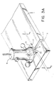
- the router 6 is placed on the surface 10 of the base member 9 as shown in the embodiment of FIGS. 3a and 3b, wherein the base member 9 faces with its stepped surface 11 downwardly.
- the workpiece 1 is placed onto the surface portion 13 in abutment therewith, the base member 9 is fixed to the flange of the router 6 by screws and moved along the workpiece 1 (FIG. 3a).
- an alternating contour surface 3 is produced on the workpiece 1.
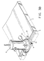
- the router bit 7 is rotated and the router is moved along the workpiece 2, so that a alternating contour surface 4 is produced in the latter (FIG. 3b).
- the routing of the workpieces 1 and 2 can be performed simultaneously or successively.
- the thusly produced alternating contour surface 3 and 4 exactly mate with one another. During their production no resetting of the router bit 7 is required.
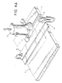
- FIGS. 4a and 4b show the method of the invention in accordance with another embodiment.
- the base member 9 is turned with its surface 11 upwardly.
- the router 6 is placed on the upper surface of the workpiece 1 so that its flange laterally abuts against a side surface 15 of the lower step of the base member.
- the router bit 7 is rotated and the router is moved longitudinally along the workpiece 1 so as to cut it off from a remaining portion and to produce the alternating contour surface 3 on the workpiece 1.
- the base member 9 is placed with its surface 10 on the workpiece 2 as shown in FIG. 4b.
- the router 6 is placed on surface portion 12 of the surface 11 so that it laterally abuts against a side surface 16 between the surface portions 12 and 13.
- the router bit 7 is rotated and the router is moved along the workpiece 2 so as to produce the alternating contour surface 4 on the latter.
- the height h1 of the lower portion of the base member 9, which is limited between the surface 10 and the surface portion 12 of the surface 11, is equal to half-pitch or to integer multiple of half-pitch of the alternating contour surface 8 of the router bit 7.
- the method in accordance with the embodiment of FIGS. 4a and 4b can be performed.
- the difference between the height h2 of a higher portion of the base member 9 which is limited between the surface 10 and the surface portion 13 of the surface 11, and the height h1 is also equal to half-pitch or integer multiple of half-pitch of the alternating contour surface 8 of the router bit 7.
- the method in accordance with the embodiment of FIGS. 3a and 3b can be performed.
- the surface of the router bit can be formed somewhat differently for example as shown in FIG. 5 with a surface 8' including alternating conical and circular cylindrical portions differently.
- the cross-section of the surface 8' of the router bit is formed by a plurality of straight portions which are alternatingly inclined to the central axis of the router bit in opposite directions.
Landscapes
- Engineering & Computer Science (AREA)
- Life Sciences & Earth Sciences (AREA)
- Mechanical Engineering (AREA)
- Wood Science & Technology (AREA)
- Forests & Forestry (AREA)
- Milling, Drilling, And Turning Of Wood (AREA)
- Milling Processes (AREA)
Abstract
Description
- The present invention relates to a device for and a method of producing workpieces with alternating contour mating surfaces.
- Devices and methods of the above mentioned general type are known in the art. Alternating contour mating surfaces are produced on workpieces for connecting them with one another along the alternating contour surfaces so as to form a strong formlocking joint. For producing such alternating contour mating surfaces, routers with router bits are used. For producing two workpieces with respective two alternating contour mating surfaces, first one workpiece is worked with a router bit to form its alternating contour surface. Then, the power tool has to be reset and the alternating contour surface on the second workpiece is formed. It is to be understood that the resetting of the router bit is an undesirable time and labor consuming operation, and it would be of advantage to produce the above mentioned workpieces without resetting of the router bit.
- Moreover, if the amount a bit protrudes during the operation is not exact, or in other words, the bit is not at a vertically tangent point to one of the curved surfaces with alternating contour, the routed surface could have a brittle feathered edge mating surfaces.
- Accordingly, it is an object of the present invention to provide a device for and a method of producing two workpieces with alternating contour mating surfaces, which eliminate the disadvantages of the prior art.
- More particularly it is an object of the present invention to provide a device for and a method of producing workpieces with alternating contour mating surface, which do not require resetting of a router bit in a router.
- In keeping with these objects and with others which will become apparent hereinafter, one feature of the present invention resides in a device for and a method of producing workpieces with alternating contour mating surfaces in accordance with which a router with a rotatable router bit having an alternating contour working surface which corresponds to alternating contour surfaces of workpieces is used, and a base member is utilized which has one substantially flat surface and another opposite surface with first and second surface portions which are offset relative to one another. When the router with the router bit is placed onto the one flat surface, the alternating contour mating surfaces on two workpieces can be produced by placing the workpieces successively on one surface portion and on the other surface portion of the other surface of the base member. On the other hand, the router bit can be placed on one surface portion and then on the other surface portion of the other surface of the base member, while both workpieces can be placed on the one flat surface of the base member. In this device and with this method, two workpieces are produced with mating alternating contour surfaces without the resetting of the router bit in a router. Moreover, the chance of misalignment of the router bit is significantly reduced.
- For providing the exact mating of the alternating contour surfaces, the first and second portions of the other surface of the base member can be offset relative to one another by a half pitch of the alternating contour of the mating surfaces or a multiple of the half-pitch thereof.
- The base member can be provided with a central opening in the region when the first and second surfaces merge into one another, so that the router bit extends through the central opening. On the other hand, the base member can be solid so that the router can be placed on the respective surface near its lateral edge so that the router bit extends laterally outwardly beyond the base member.
-
- FIG. 1 ist a view showing two workpieces with alternating contour surfaces, to be produced in accordance with the present invention and connected with one another to form a joint;
- FIG. 2 ist a view showing a base member for a device and a method in accordance with the present invention;
- FIG. 2A is a view schematically showing a router bit for a router for producing workpieces in accordance with the present invention;
- FIGS.3a and 3b are views illustrating a method for producing alternating contour surfaces on two workpieces in accordance with one embodiment of the invention;
- FIGS. 4a and 4b are views substantially corresponding to the view of FIG. 3, but showing the method of producing alternating contour surfaces on workpieces in accordance with another embodiment of the present invention; and
- FIG. 5 is a view showing alternative configuration of workpieces and router bits for their manufacture.
- A device and a method in accordance with the present investion is used for producing workpieces with alternating contour mating surfaces. The workpieces are identified with
reference numerals 1 and 2 in FIG. 1 and have alternatingcontour surfaces workpieces 1 and 2 are connected with one another for example by introducing a binder between thealternating contour surfaces workpieces 1 and 2 toward one another so as to obtain a final product which is identified as a whole withreference numeral 5. - The
alternating contour surfaces workpieces 1 and 2 are produced by arouter 6 provided with arotatable router bit 7. The router bit has a alternating contour working surface which corresponds to the alternating contour surfaces of the workpieces. It is rotated by a not shown rotary drive provided in therouter 6. - In accordance with the present invention, a
base member 9 is provided, so as to be associated with therouter 6 for producing the alternating contour surfaces of the workpieces. Thebase member 9 has oneflat surface 10, and another opposite surface 11 which is provided with twosurface portions surface portions surface - The
base member 9 can be provided with acentral opening 14 for therouter bit 7. However, it is also possible that themember 9 does not have a central opening as will be explained hereinbelow. - For producing
alternating contour surfaces workpieces 1 and 2 to be joined together, therouter 6 is placed on thesurface 10 of thebase member 9 as shown in the embodiment of FIGS. 3a and 3b, wherein thebase member 9 faces with its stepped surface 11 downwardly. The workpiece 1 is placed onto thesurface portion 13 in abutment therewith, thebase member 9 is fixed to the flange of therouter 6 by screws and moved along the workpiece 1 (FIG. 3a). As a result of this, analternating contour surface 3 is produced on the workpiece 1. Then theworkpiece 2 is placed on thesurface portion 12 of the surface 11 of thebase member 9 in abutment therewith, therouter bit 7 is rotated and the router is moved along theworkpiece 2, so that aalternating contour surface 4 is produced in the latter (FIG. 3b). The routing of theworkpieces 1 and 2 can be performed simultaneously or successively. The thusly producedalternating contour surface router bit 7 is required. - FIGS. 4a and 4b show the method of the invention in accordance with another embodiment. In this embodiment the
base member 9 is turned with its surface 11 upwardly. First, as shown in FIG. 4a, therouter 6 is placed on the upper surface of the workpiece 1 so that its flange laterally abuts against aside surface 15 of the lower step of the base member. Then therouter bit 7 is rotated and the router is moved longitudinally along the workpiece 1 so as to cut it off from a remaining portion and to produce thealternating contour surface 3 on the workpiece 1. After this, thebase member 9 is placed with itssurface 10 on theworkpiece 2 as shown in FIG. 4b. Therouter 6 is placed onsurface portion 12 of the surface 11 so that it laterally abuts against aside surface 16 between thesurface portions router bit 7 is rotated and the router is moved along theworkpiece 2 so as to produce thealternating contour surface 4 on the latter. - In accordance with an advantageous feature of the present invention the height h1 of the lower portion of the
base member 9, which is limited between thesurface 10 and thesurface portion 12 of the surface 11, is equal to half-pitch or to integer multiple of half-pitch of thealternating contour surface 8 of therouter bit 7. With such dimensioning of thebase member 9, the method in accordance with the embodiment of FIGS. 4a and 4b can be performed. The difference between the height h2 of a higher portion of thebase member 9 which is limited between thesurface 10 and thesurface portion 13 of the surface 11, and the height h1 is also equal to half-pitch or integer multiple of half-pitch of thealternating contour surface 8 of therouter bit 7. With the latter mentioned dimensioning, the method in accordance with the embodiment of FIGS. 3a and 3b can be performed. - The surface of the router bit can be formed somewhat differently for example as shown in FIG. 5 with a surface 8' including alternating conical and circular cylindrical portions differently. In the embodiment of FIG. 5 the cross-section of the surface 8' of the router bit is formed by a plurality of straight portions which are alternatingly inclined to the central axis of the router bit in opposite directions.
Claims (8)
- A device for producing mating alternating contour surface on workpieces, comprising a rotatable and displaceable working tool (7) with an alternating contour surface (8) which has a predetermined pitch, characterized in having a base member (9) arranged to be placed on a workpiece (1) and to guide said tool (7) during said displacement, said base member (9) having a first substantially flat surface (10), and a second opposite surface (11) transversely spaced from said first surface and provided with two surface portions (12, 13) which are spaced from one another by a distance which is substantially equal to half-pitch or to integer multiple of half-pitch of said alternating contour surface (8) of said tool (7).
- A device as defined in claim 1, wherein said surface portions (12, 13) of said second surface (11) having one surface portion (12) which is located closer to said first surface (10) said one surface portion (12) being spaced from said first surface by a distance which is substantially equal to half-pitch of said tool (7).
- A device as defined in claim 1, wherein said surface portions (12, 13) of said second surface (11) having one surface portion which is located closer to said first surface (10), said one surface portion (12) being spaced from said first surface by a distance which is sub-stantially equal to integer multiple of half-pitch of said tool (7).
- A device as defined in claim 1, wherein said tool (7) is connected with said base member (9) and is displaceable together with the latter; and further comprising means for connecting said tool with said base member.
- A device as defined in claim 1, wherein said tool (7) is displaceable relative to said base member (9), said base member having a side surface formed so as to guide said tool (7) during its displacement relative to said base member (9).
- A method of producing mating alternating contour surface on workpieces, comprises the steps of providing a rotatable and displaceable tool (7) having a alternating contour working surface (8); arranging on a workpiece (1) a base member (9) which has a first substantially flat surface (10) and a second opposite surface (11) which is spaced transversely from the first surface (10) and has two surface portions (12, 13) which are offset from one another in a transverse direction; and displacing the tool (7) so that it is guided by the base member (9) so as to produce mating alternating contour surfaces (3, 4) in two workpieces (1, 2).
- A method as defined in claim 6, wherein said displacing includes placing one of the surface portions (12, 13) on one of the workpieces (1, 2), placing the other of the surface portions (13, 12) on the other of the two workpieces (2, 1), and jointly displacing the tool (7) together with the base member (9) relative to the one workpiece (1) and the other workpiece (2).
- A method as defined in claim 6, wherein said displacing includes placing the base member (9) with its first surface (10) on one of the workpieces (1, 2) and on the other of two workpieces (2, 1), displacing the tool (7) relative to one of the workpieces (1) and relative to the base member (9) with lateral guidance of the tool (7) against a side surface of the base member, and displacing the tool (7) relative to the other workpiece (2) and relative to the base member (9) with guidance of the tool (7) over one of the surface portions (12, 13) of the second surface (11) of the base member (9).
Applications Claiming Priority (2)
| Application Number | Priority Date | Filing Date | Title |
|---|---|---|---|
| US07/249,852 US4860809A (en) | 1988-09-27 | 1988-09-27 | Device for and method of producing workpieces with alternating contour mating surfaces |
| US249852 | 1988-09-27 |
Publications (2)
| Publication Number | Publication Date |
|---|---|
| EP0436638A1 EP0436638A1 (en) | 1991-07-17 |
| EP0436638B1 true EP0436638B1 (en) | 1993-07-14 |
Family
ID=22945281
Family Applications (1)
| Application Number | Title | Priority Date | Filing Date |
|---|---|---|---|
| EP89911373A Expired - Lifetime EP0436638B1 (en) | 1988-09-27 | 1989-09-23 | Device for and method of producing workpieces with alternating contour mating surfaces |
Country Status (4)
| Country | Link |
|---|---|
| US (1) | US4860809A (en) |
| EP (1) | EP0436638B1 (en) |
| DE (1) | DE68907606T2 (en) |
| WO (1) | WO1990003248A1 (en) |
Families Citing this family (28)
| Publication number | Priority date | Publication date | Assignee | Title |
|---|---|---|---|---|
| US4860809A (en) * | 1988-09-27 | 1989-08-29 | Robert Bosch Power Tool Corporation | Device for and method of producing workpieces with alternating contour mating surfaces |
| US4993465A (en) * | 1989-12-04 | 1991-02-19 | Robert Bosch Gmbh | Router tool for and method of producing workpieces with alternating contour mating surfaces |
| US5215134A (en) * | 1992-09-09 | 1993-06-01 | Gudeman Bill J | Matched edge jointer |
| IE922750A1 (en) * | 1992-10-20 | 1994-04-20 | Gordon Russell Ltd | Furniture manufacturing method and apparatus |
| US5445198A (en) * | 1994-08-31 | 1995-08-29 | Ryobi Motor Products Corporation | Router sub-base |
| US5740847A (en) * | 1996-09-23 | 1998-04-21 | Eric E. Lakso | Portable power tool cutting guide |
| US5996659A (en) * | 1998-01-09 | 1999-12-07 | Burgess; Michael | Matched pair of plywood edge-banding router bits |
| US7467651B2 (en) | 2001-11-09 | 2008-12-23 | Nomis Llc | Tool attachment system and router attachment and method incorporating same |
| DE602004022777D1 (en) | 2003-02-12 | 2009-10-08 | Nomis Llc | TOOL TUBING SYSTEM AND MILLING UNIT AND METHOD THEREFOR |
| US7434604B2 (en) | 2004-07-30 | 2008-10-14 | Black & Decker Inc. | Jig apparatus |
| US7857020B2 (en) | 2004-07-30 | 2010-12-28 | Black & Decker Inc. | Jig apparatus |
| US7455089B2 (en) | 2004-07-30 | 2008-11-25 | Black & Decker Inc. | Jig apparatus |
| US7195043B1 (en) | 2005-11-01 | 2007-03-27 | Neff Leslie A | Router guide |
| USD575312S1 (en) | 2006-08-22 | 2008-08-19 | Black & Decker Inc. | Outrigger for a jig apparatus |
| USD559287S1 (en) | 2006-08-22 | 2008-01-08 | Black & Decker Corporation | Variable-spaced finger assembly |
| USD574864S1 (en) | 2006-08-22 | 2008-08-12 | Black & Decker Inc | Mortise and tenon assembly |
| USD573615S1 (en) | 2006-08-22 | 2008-07-22 | Black & Decker Inc. | Dust collector |
| USD559875S1 (en) | 2006-08-22 | 2008-01-15 | Black & Decker Corporation | Half-blind router bit depth guide |
| USD571836S1 (en) | 2006-08-22 | 2008-06-24 | Black & Decker Inc. | Box joint template |
| USD577752S1 (en) | 2006-08-22 | 2008-09-30 | Black & Decker Inc. | Jig apparatus |
| USD560235S1 (en) | 2006-08-22 | 2008-01-22 | Black & Decker Corporation | Sliding tapered dovetail and fixed half-blind dovetail template |
| USD569882S1 (en) | 2006-08-22 | 2008-05-27 | Black & Decker Inc. | Miniature variable-spaced finger assembly |
| US9726469B2 (en) | 2012-08-31 | 2017-08-08 | Nomis Llc | Turnlock small circle compass attachment |
| USD738178S1 (en) | 2014-05-16 | 2015-09-08 | Nomis Llc | Tool adaptor plate |
| USD844469S1 (en) | 2017-03-16 | 2019-04-02 | Nomis Llc | Circle compass |
| US11173624B2 (en) | 2017-05-09 | 2021-11-16 | Nomis Llc | Router base having adjustable mounting slots |
| CN112847686B (en) * | 2020-12-31 | 2022-03-22 | 浙江大学台州研究院 | A fully automatic multi-station bamboo and wood processing equipment |
| US12583145B2 (en) | 2023-07-28 | 2026-03-24 | Bam Ip Holding Llc | Router attachment adaptor and cover for same |
Family Cites Families (12)
| Publication number | Priority date | Publication date | Assignee | Title |
|---|---|---|---|---|
| US1871637A (en) * | 1931-10-23 | 1932-08-16 | Charles F Vance | Woodworking machine |
| CH169420A (en) * | 1933-08-17 | 1934-05-31 | Tuetsch & Zimmermann | Butt joint connection on wooden frames, process for their production and device for carrying out the process. |
| US2673582A (en) * | 1950-10-20 | 1954-03-30 | Thomes Charles Edward | Work gauge for use in forming joints in pattern or like sections |
| US3119207A (en) * | 1962-01-02 | 1964-01-28 | Warren L Nall | Door edge finishing tool |
| DE2421954C2 (en) * | 1974-05-07 | 1983-09-08 | Eugen Lutz GmbH u. Co Maschinenfabrik, 7130 Mühlacker | Angle guide for stationary or mobile hand routers |
| US3943985A (en) * | 1974-07-29 | 1976-03-16 | Wowczyk Hans J | Apparatus for cutting aligned notches in parallel wooden frame members |
| US3951189A (en) * | 1974-10-15 | 1976-04-20 | Industrial Woodworking Machine Co., Inc. | Apparatus for indexing a cutting head |
| AU502606B2 (en) * | 1975-10-24 | 1979-08-02 | Netcom (Australasia) Pty. Ltd | Guiding device for power tool |
| US4044805A (en) * | 1976-02-04 | 1977-08-30 | Gronholz Donald D | Router guide unit |
| US4051880A (en) * | 1976-10-29 | 1977-10-04 | The Singer Company | Dustless routers |
| US4768570A (en) * | 1987-06-22 | 1988-09-06 | Honeyman George R | Cutting support and guide |
| US4860809A (en) * | 1988-09-27 | 1989-08-29 | Robert Bosch Power Tool Corporation | Device for and method of producing workpieces with alternating contour mating surfaces |
-
1988
- 1988-09-27 US US07/249,852 patent/US4860809A/en not_active Expired - Fee Related
-
1989
- 1989-09-23 WO PCT/EP1989/001108 patent/WO1990003248A1/en not_active Ceased
- 1989-09-23 DE DE89911373T patent/DE68907606T2/en not_active Expired - Fee Related
- 1989-09-23 EP EP89911373A patent/EP0436638B1/en not_active Expired - Lifetime
Also Published As
| Publication number | Publication date |
|---|---|
| EP0436638A1 (en) | 1991-07-17 |
| WO1990003248A1 (en) | 1990-04-05 |
| US4860809A (en) | 1989-08-29 |
| DE68907606T2 (en) | 1993-10-28 |
| DE68907606D1 (en) | 1993-08-19 |
Similar Documents
| Publication | Publication Date | Title |
|---|---|---|
| US4860809A (en) | Device for and method of producing workpieces with alternating contour mating surfaces | |
| US4849602A (en) | Method for fabricating cutting pieces | |
| US6491482B1 (en) | Milling method | |
| EP0117242B1 (en) | Cutting insert for thread cutting | |
| US5871314A (en) | Device for balancing rotors by material removal | |
| EP0119175A1 (en) | Thread cutting insert | |
| US5449255A (en) | Cutting insert having multiple chip breaker surfaces | |
| KR20060087115A (en) | Electric Discharge Machining Method for Turbine Blades and Electric Discharge Machining Apparatus Applied to the Turbine Blade | |
| US11890687B2 (en) | Milling tool and workpiece machining method | |
| US4086016A (en) | Cutting tool | |
| US5988956A (en) | Hole cutter | |
| US6745446B1 (en) | Method for producing mechanical parts from an assembly of layers which are turned over during machining, and the elemental laminations and assembled parts produced | |
| US3951183A (en) | Forming tool for coil-end components of electric machines | |
| US6471452B2 (en) | Process and apparatus for balancing rotating bodies, in particular rotors of electric motors | |
| CA1211686A (en) | Saw and method for the manufacture thereof | |
| WO1997020259A1 (en) | Method and device for milling three-dimensional workpieces | |
| EP0514099B1 (en) | Die-shaping apparatus and process | |
| US6125520A (en) | Shake and break process for sheet metal | |
| US4993465A (en) | Router tool for and method of producing workpieces with alternating contour mating surfaces | |
| US4481700A (en) | Panel punch | |
| FI87428C (en) | Method and apparatus for manufacturing drills | |
| US20050196245A1 (en) | Method for producing a surface, and a surface | |
| US5368422A (en) | Method for manufacturing golf club heads or their prototypes | |
| US5043551A (en) | Wire cut-type electric discharging method | |
| JPH02116428A (en) | Boring method and device for oblique hole |
Legal Events
| Date | Code | Title | Description |
|---|---|---|---|
| PUAI | Public reference made under article 153(3) epc to a published international application that has entered the european phase |
Free format text: ORIGINAL CODE: 0009012 |
|
| 17P | Request for examination filed |
Effective date: 19901205 |
|
| AK | Designated contracting states |
Kind code of ref document: A1 Designated state(s): CH DE FR GB IT LI |
|
| RAP3 | Party data changed (applicant data changed or rights of an application transferred) |
Owner name: ROBERT BOSCH GMBH |
|
| 17Q | First examination report despatched |
Effective date: 19920925 |
|
| GRAA | (expected) grant |
Free format text: ORIGINAL CODE: 0009210 |
|
| AK | Designated contracting states |
Kind code of ref document: B1 Designated state(s): CH DE FR GB IT LI |
|
| REF | Corresponds to: |
Ref document number: 68907606 Country of ref document: DE Date of ref document: 19930819 |
|
| ET | Fr: translation filed | ||
| ITF | It: translation for a ep patent filed | ||
| PGFP | Annual fee paid to national office [announced via postgrant information from national office to epo] |
Ref country code: CH Payment date: 19931208 Year of fee payment: 5 |
|
| PLBE | No opposition filed within time limit |
Free format text: ORIGINAL CODE: 0009261 |
|
| STAA | Information on the status of an ep patent application or granted ep patent |
Free format text: STATUS: NO OPPOSITION FILED WITHIN TIME LIMIT |
|
| 26N | No opposition filed | ||
| PG25 | Lapsed in a contracting state [announced via postgrant information from national office to epo] |
Ref country code: LI Effective date: 19940930 Ref country code: CH Effective date: 19940930 |
|
| REG | Reference to a national code |
Ref country code: CH Ref legal event code: PL |
|
| REG | Reference to a national code |
Ref country code: GB Ref legal event code: IF02 |
|
| PGFP | Annual fee paid to national office [announced via postgrant information from national office to epo] |
Ref country code: FR Payment date: 20040917 Year of fee payment: 16 |
|
| PG25 | Lapsed in a contracting state [announced via postgrant information from national office to epo] |
Ref country code: IT Free format text: LAPSE BECAUSE OF NON-PAYMENT OF DUE FEES;WARNING: LAPSES OF ITALIAN PATENTS WITH EFFECTIVE DATE BEFORE 2007 MAY HAVE OCCURRED AT ANY TIME BEFORE 2007. THE CORRECT EFFECTIVE DATE MAY BE DIFFERENT FROM THE ONE RECORDED. Effective date: 20050923 |
|
| PG25 | Lapsed in a contracting state [announced via postgrant information from national office to epo] |
Ref country code: FR Free format text: LAPSE BECAUSE OF NON-PAYMENT OF DUE FEES Effective date: 20060531 |
|
| REG | Reference to a national code |
Ref country code: FR Ref legal event code: ST Effective date: 20060531 |
|
| PGFP | Annual fee paid to national office [announced via postgrant information from national office to epo] |
Ref country code: DE Payment date: 20061110 Year of fee payment: 18 |
|
| PGFP | Annual fee paid to national office [announced via postgrant information from national office to epo] |
Ref country code: GB Payment date: 20070921 Year of fee payment: 19 |
|
| PG25 | Lapsed in a contracting state [announced via postgrant information from national office to epo] |
Ref country code: DE Free format text: LAPSE BECAUSE OF NON-PAYMENT OF DUE FEES Effective date: 20080401 |
|
| GBPC | Gb: european patent ceased through non-payment of renewal fee |
Effective date: 20080923 |
|
| PG25 | Lapsed in a contracting state [announced via postgrant information from national office to epo] |
Ref country code: GB Free format text: LAPSE BECAUSE OF NON-PAYMENT OF DUE FEES Effective date: 20080923 |