EP0436522B1 - Source of coherent short wavelength radiation - Google Patents
Source of coherent short wavelength radiation Download PDFInfo
- Publication number
- EP0436522B1 EP0436522B1 EP91850002A EP91850002A EP0436522B1 EP 0436522 B1 EP0436522 B1 EP 0436522B1 EP 91850002 A EP91850002 A EP 91850002A EP 91850002 A EP91850002 A EP 91850002A EP 0436522 B1 EP0436522 B1 EP 0436522B1
- Authority
- EP
- European Patent Office
- Prior art keywords
- charged particles
- source
- coherent
- path
- wavelength radiation
- Prior art date
- Legal status (The legal status is an assumption and is not a legal conclusion. Google has not performed a legal analysis and makes no representation as to the accuracy of the status listed.)
- Expired - Lifetime
Links
- 230000001427 coherent effect Effects 0.000 title claims description 36
- 230000005855 radiation Effects 0.000 title claims description 24
- 239000002245 particle Substances 0.000 claims description 32
- 230000005540 biological transmission Effects 0.000 claims description 15
- 230000005684 electric field Effects 0.000 claims description 14
- 238000004519 manufacturing process Methods 0.000 claims description 6
- CURLTUGMZLYLDI-UHFFFAOYSA-N Carbon dioxide Chemical compound O=C=O CURLTUGMZLYLDI-UHFFFAOYSA-N 0.000 description 10
- 238000003860 storage Methods 0.000 description 9
- 239000007789 gas Substances 0.000 description 7
- 229910002092 carbon dioxide Inorganic materials 0.000 description 5
- 238000009826 distribution Methods 0.000 description 4
- 230000000694 effects Effects 0.000 description 4
- 238000003384 imaging method Methods 0.000 description 4
- 238000000034 method Methods 0.000 description 4
- 238000002347 injection Methods 0.000 description 3
- 239000007924 injection Substances 0.000 description 3
- 239000010453 quartz Substances 0.000 description 3
- VYPSYNLAJGMNEJ-UHFFFAOYSA-N silicon dioxide Inorganic materials O=[Si]=O VYPSYNLAJGMNEJ-UHFFFAOYSA-N 0.000 description 3
- 239000007787 solid Substances 0.000 description 3
- 230000008859 change Effects 0.000 description 2
- 238000010894 electron beam technology Methods 0.000 description 2
- 230000004907 flux Effects 0.000 description 2
- 238000001727 in vivo Methods 0.000 description 2
- 239000012212 insulator Substances 0.000 description 2
- 230000003993 interaction Effects 0.000 description 2
- 239000000463 material Substances 0.000 description 2
- 238000000386 microscopy Methods 0.000 description 2
- 230000001960 triggered effect Effects 0.000 description 2
- 229910001218 Gallium arsenide Inorganic materials 0.000 description 1
- 229910052772 Samarium Inorganic materials 0.000 description 1
- 238000004458 analytical method Methods 0.000 description 1
- 238000012984 biological imaging Methods 0.000 description 1
- 239000012620 biological material Substances 0.000 description 1
- 239000001569 carbon dioxide Substances 0.000 description 1
- 239000012141 concentrate Substances 0.000 description 1
- 238000010276 construction Methods 0.000 description 1
- 238000010586 diagram Methods 0.000 description 1
- 239000003989 dielectric material Substances 0.000 description 1
- 238000006073 displacement reaction Methods 0.000 description 1
- 238000004134 energy conservation Methods 0.000 description 1
- 238000005516 engineering process Methods 0.000 description 1
- 229910052751 metal Inorganic materials 0.000 description 1
- 239000002184 metal Substances 0.000 description 1
- 238000012986 modification Methods 0.000 description 1
- 230000004048 modification Effects 0.000 description 1
- 238000004321 preservation Methods 0.000 description 1
- 230000008569 process Effects 0.000 description 1
- KZUNJOHGWZRPMI-UHFFFAOYSA-N samarium atom Chemical compound [Sm] KZUNJOHGWZRPMI-UHFFFAOYSA-N 0.000 description 1
- 229910052594 sapphire Inorganic materials 0.000 description 1
- 239000010980 sapphire Substances 0.000 description 1
- 229910052710 silicon Inorganic materials 0.000 description 1
- 239000010703 silicon Substances 0.000 description 1
- 239000000243 solution Substances 0.000 description 1
- 238000010186 staining Methods 0.000 description 1
- 230000001360 synchronised effect Effects 0.000 description 1
- 230000005469 synchrotron radiation Effects 0.000 description 1
- XLYOFNOQVPJJNP-UHFFFAOYSA-N water Substances O XLYOFNOQVPJJNP-UHFFFAOYSA-N 0.000 description 1
- 238000003963 x-ray microscopy Methods 0.000 description 1
- 229910052727 yttrium Inorganic materials 0.000 description 1
- VWQVUPCCIRVNHF-UHFFFAOYSA-N yttrium atom Chemical compound [Y] VWQVUPCCIRVNHF-UHFFFAOYSA-N 0.000 description 1
Images



Classifications
-
- H—ELECTRICITY
- H05—ELECTRIC TECHNIQUES NOT OTHERWISE PROVIDED FOR
- H05H—PLASMA TECHNIQUE; PRODUCTION OF ACCELERATED ELECTRICALLY-CHARGED PARTICLES OR OF NEUTRONS; PRODUCTION OR ACCELERATION OF NEUTRAL MOLECULAR OR ATOMIC BEAMS
- H05H5/00—Direct voltage accelerators; Accelerators using single pulses
- H05H5/02—Details
-
- H—ELECTRICITY
- H01—ELECTRIC ELEMENTS
- H01S—DEVICES USING THE PROCESS OF LIGHT AMPLIFICATION BY STIMULATED EMISSION OF RADIATION [LASER] TO AMPLIFY OR GENERATE LIGHT; DEVICES USING STIMULATED EMISSION OF ELECTROMAGNETIC RADIATION IN WAVE RANGES OTHER THAN OPTICAL
- H01S4/00—Devices using stimulated emission of electromagnetic radiation in wave ranges other than those covered by groups H01S1/00, H01S3/00 or H01S5/00, e.g. phonon masers, X-ray lasers or gamma-ray lasers
-
- H—ELECTRICITY
- H05—ELECTRIC TECHNIQUES NOT OTHERWISE PROVIDED FOR
- H05H—PLASMA TECHNIQUE; PRODUCTION OF ACCELERATED ELECTRICALLY-CHARGED PARTICLES OR OF NEUTRONS; PRODUCTION OR ACCELERATION OF NEUTRAL MOLECULAR OR ATOMIC BEAMS
- H05H7/00—Details of devices of the types covered by groups H05H9/00, H05H11/00, H05H13/00
-
- H—ELECTRICITY
- H05—ELECTRIC TECHNIQUES NOT OTHERWISE PROVIDED FOR
- H05H—PLASMA TECHNIQUE; PRODUCTION OF ACCELERATED ELECTRICALLY-CHARGED PARTICLES OR OF NEUTRONS; PRODUCTION OR ACCELERATION OF NEUTRAL MOLECULAR OR ATOMIC BEAMS
- H05H9/00—Linear accelerators
- H05H9/02—Travelling-wave linear accelerators
Definitions
- the present invention relates to the production of coherent short wavelength radiation and, more particularly, to the production of coherent short wavelength radiation (e.g., X-rays and/or ultraviolet) utilizing the Compton scattering effect.
- coherent short wavelength radiation e.g., X-rays and/or ultraviolet
- a coherent source of X-rays in the energy region of 500 to 1000 eV can be used as a first component of an X-ray microscope capable of very high resolution, to study biological materials in vivo, i.e., in their hydrated form.
- This source is the equivalent of the light source in a conventional microscope.
- Quasi-coherent X-ray beams in the water window energy range are produced by storage rings; the synchrotron radiation from these machines is filtered by selecting small angular apertures of the radiation passed through a very small hole, and through a monochromator. As a consequence, the photon flux is reduced enormously (by some seven orders of magnitude or more).
- these sources have been used to make proof-of-principle holographic images of simple objects; scanning images and quasi-optical images have been shown as well.
- the intensity available from storage rings does not allow short exposure times; exposures vary from several minutes to several hours (see Table 1 below adopted from M.R. Howells, "Soft X-Ray Imaging for the Life Sciences", Advanced Light Source Report , (LSGN-008) LBL-27420)).
- Luccio et al. "Coherent Backscattering in the Soft X-Ray Region", BNL 38050 (June 1986) propose a method to generate monochromatic X-rays: by scattering a photon beam on a bunch of electrons, whose density in the direction of motion is appropriately modulated (to be in resonance with the Doppler-shifted wavelength of the incoming laser), a significant increase in the scattered radiation intensity can be obtained. Also, a degree of coherence is present in the scattered beam.
- the modulation of the bunch is obtained via the interaction of a magnetic field and the laser light itself, giving an energy modulation first. This energy modulation is transformed in spatial modulation, as required, by transporting the modulated bunch for some distance.
- EP-A-0 105 032 discloses a source of coherent short wavelength radiation using the Compton backward scattering effect.
- This known apparatus for producing X-rays comprises means for emitting charged particles (electrons) that travel along a path, an accelerator for accelerating said charged particles travelling along said path to produce dense bunches of said charged particles, and a source of coherent light for producing a photon beam in a direction substantially opposite to the direction of the accelerated particles and into a colliding relationship with said focussed accelerated charged particles, such that, as a result of Compton backward scattering, coherent short length wavelength radiation is produced in substantially the same direction as the direction of the photon beam.
- Any electron accelerator is disclosed to be useful.
- an assembly including a so-called racetrack closed-loop storage ring in which electrons circulate repeatedly at a predetermined energy level.
- Various types of electron injectors are described to be useful.
- a microtron in which electrons are accelerated along a spiral path to the desired injection velocity and injected tangentially into the racetrack, one path segment of which is disposed co-linear with the path of the photon beam to provide for the Compton collision.
- the microtron/racetrack combination is useful for the indicated purpose but requires, i.a., expensive equipment for keeping the electrons within the closed-loop.
- Another object is to provide a relatively compact source of coherent short wavelength radiation which can be used in a laboratory type setting.
- a photon beam from a laser is scattered on a high energy electron bunch from a compact pulse power linac to produce coherent short wavelength radiation ranging from X-rays to the far ultraviolet (i.e., from 1 Kev to 10 eV).
- the source of coherent short wavelength radiation comprises a high gradient linear accelerator for accelerating said charged particles along a linear path, said linear accelerator comprising a plurality of electrode gaps disposed in series, each of said electrode gaps being defined by a pair of spaced electrodes disposed transverse to said path, each of said electrodes having an aperture through which said linear path extends, said electrodes each being coupled to a source of energy pulses by a respective transmission line, the transmission lines for each pair of spaced electrodes being open circuited at their ends with respect to one another, said charged particles being subjected to an accelerating force generated by an electric field which is derived from each of said energy pulses as said charged particles pass through said electrode gaps.
- the present invention there is no need to modulate the longitudinal density of the electron bunch to be in resonance with the Doppler shifted wavelength of the incoming laser.
- Another advantageous aspect of the present invention is that the intensity of the backscattered beam of radiation increases by a factor of the order of the number of electrons acting coherently. Accordingly, the present invention provides, for the first time, a relatively compact source of coherent short wavelength radiation with sufficient intensity for microscopy.
- the high energy electrons utilized for backward Compton scattering in the present invention are accelerated by a novel pulse power linac structure similar in principle to that described and claimed in EP-A-0 359 732.
- the linac basically consists of an array of radial directed waveguides that act as line transformers where high voltage pulses travel inward from the periphery and are ultimately applied to an electron beam extracted from a high field cathode.
- Such a structure produces very short intense pulses of high energy electrons in a very short fly path.
- a short pulse of high energy electrons from the linac are directed essentially head-on at a beam of coherent, low energy photons, such as from a CO2 laser, resulting in backscattering of the photons and the production of coherent short wavelength radiation in the required energy range for biological imaging.
- the present invention has four primary components: a particle generator or electron source 5, a linac 10, a magnet array 20 (optional) and a laser 30.
- electron source 5 generates electrons, which are accelerated by linac 10, concentrated by magnet array 20, and directed substantially head-on at coherent light from laser 30, resulting in backscattering of the laser light and the production of coherent X-rays.
- Electron source 5 is a high field diode, preferably having a structure similar to one of the transformers that make up the accelerator described below.
- the cathode of the diode (made of a metal with a high quantum efficiency in the ultraviolet, such as yttrium or samarium) is bombarded by UV laser light from a KrF laser or Nd:YAG quadrupled laser.
- linac 10 of the present invention comprises a plurality of accelerating gaps arranged in series. These gaps are energized in sequence by releasing or switching a single pulse of energy which propagates simultaneously along a plurality of transmission lines, each of which feeds an individual one of the gaps.
- the transmission lines are graduated in length so that the power pulse is present in each gap as the accelerator electron bunch passes therethrough.
- the difference between the structure of the accelerator used in the present invention and that of the prior application is that, for a low-energy beam, the number of accelerating stages is small (less than 50) and therefore, one can avoid the twist of the lines, simply because the number of switches needed is manageable.
- the lines were twisted to minimize or reduce the number of switches.
- the previous design could be used equally as well in the present invention.
- FIG. 2 A schematic of the accelerating structure of multi-element linac 10 of the present invention is shown in Fig. 2.
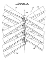
- FIG. 6 A top view of the structure is illustrated in Fig. 6, showing that the elements 25 of linac 10 are layered upon each other with 90° offset between adjacent elements. Although a 90° offset is preferred, any other even number of subdivisions, such as 180°(4), 45°(8), or 60°(6) would work.
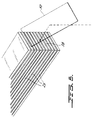
- each element 25 of linac 10 includes a pair of spaced parallel tapered plates 31, 32.
- the tapered end of each of the plates 31, 32 includes an aperture 33 through which the generally straight line particle path 39 extends.
- the means for injecting power into linac 10 is preferably provided by a charge storage plate 34 and a normally open switch 35.
- Storage plate 34 is disposed between transmission line plates 31, 32 at power input region 36.
- a mirror 50 is used to send light sequentially to each switch 35 with appropriate timing so as to effectively provide an energy gradient that appears to travel along accelerating path 39 in on upward direction with respect to Fig. 2.
- Dielectric material 38 fills the space between plates 31, 32 except at the central portions of having apertures 33 through which accelerating path 39 extends.
- the transit time for energy pulses is controlled by the dielectric constant of the material for insulator 38. Tapering of the space between plates 31 and 32, with spacing g1 at injection region 36 being greater than spacing g2 at accelerating region 37, controls the electric field at accelerating region 37.
- each of the plates 31, 32 has a width W1 at its pulse injection larger than its width W2 at the accelerating region 37.
- Fig. 5 illustrates a switch 35 for producing the single pulse of energy into linac 10.
- Switch 35 is preferably a gas avalanche, laser triggered switch used for reliable ultrafast switching of relatively high currents at moderately high voltages.
- Such a switch is described in R.E. Cassel, F. Villa, "High Speed Switching in Gases," SLAC-PUB-4858 (February 1989).
- other low energy switches such as solid state (GaAs or silicon) or photoelectric switches may be used.
- An example of a suitable solid state switch is described in E.T. Lincke, Proceedings of the Switched Power Workshop , Brookhaven National Report, Oct. 16-21, 1988; J. Fisher et al., ibid , describes a suitable photoelectric switch.
- the gas avalanche switch has an energy efficiency sufficiently high for use in a high energy collider, or in general, for machines whose final energy is of the order of 100 MV or higher.
- the solid state and photoelectric switches are both viable solutions.
- the preferred gas avalanche switch 35 shown in Fig. 5 is the switching element in a Blumlein-type pulse forming network which includes shaped quartz element 41 that is transparent to UV light and is provided with cavity 43 that is filled with a gas 42 pressurized to about 30 atmospheres. Cavity 43 extends for approximately the width of storage electrode 34, whose shaped edge portion 34a is disposed within cavity 43. Shaped edge portion 32a of transmission line plate 32 is disposed within cavity 43 while plate 31 does not extend into cavity 43. Edge portion 31a of plate 31 is disposed within slot 41a of quartz element 41. Portions of quartz element 41 are interposed between electrode 34 and plates 31, 32 and directly between plates 31, 32 in the region of electrode 34.
- Initial ionization of gas 42 results from UV laser light (from the same laser driving electron source 5 to maintain proper synchronization) that is directed into cavity 43 and concentrated relatively close to anode electrode 34a of anode 34. This causes electrons to avalanche towards anode electrode 34a. The ionized region will spread away from the initial distribution because electrons produced by the avalanche will ionize the surrounding gas 42, and because the electrons are moving under the influence of the electric field. The displacement current of the electron avalanche will induce a pulse across plates or electrodes 31, 32.
- Each section of the machine will be a parallel plate transmission line, having dimensions of g1 and w1 at the beginning, and g2 and w2 at the accelerating end.
- the factor of 2 is due to the fact that the lines are open, and therefore the reflected amplitude doubles at the expense of the magnetic field part of the electromagnetic wave.
- the voltage required on each accelerating gap will be g2E.
- the electron bunch length is 30 microns, and the accelerating gap can be as small as 500 microns.
- the size of the gap is related to the diameter of the bunch, that fixes the minimum size of the iris through which the beam is accelerated. For 100 microns diameter bunch, an iris of 200 microns is sufficient, and the ratio of the gap to iris diameter is 2.5, which reduces the actual electric field by about 30%. Therefore, the voltage on the final accelerating stage should be 2 MV.
- w1 30 mm
- g1 3 mm
- Z i 2.55 ohms
- w2 1.2 mm
- g2 0.5 mm
- Z f 110 ohms
- the voltage gain is 13.2
- the injected voltage is 152 kV. It is assumed that the pulse duration is 10 ps FWHM, for total energy of 0.1 J/pulse, a modest 10 W at a repetition rate of 100 pps.
- the energy gain/stage, neglecting beam loading will be the product of the effective gradient (3 GV/m) times the gap length, or 1.5 MeV. To obtain the energy of 50 MeV, 33 stages are required. To be conservative, the preferred embodiment includes 40 stages.
- the total accelerating length will be 20 mm; if the thickness of the electrode is 250 microns, the total length of the machine will be 40 mm.
- the lines do not have a twist in the electric field plane. This allows a very simple construction, since all the elements are identical.
- the problem of producing a trigger laser beam with 40 different focus lines is well within standard optics practice.
- the lines are grouped in four orthogonal sets (to reduce crosstalk among adjacent lines); the laser trigger is first split into four beams, and subsequently, each beam is focused onto four switches (see Fig. 2).
- the triggering laser beams may be staggered in time if the line's length is identical for all lines.
- Another option is to change the electrical length of the transmission lines, so that the electric field accelerating the electron bunch is appropriately synchronized.
- Magnet array 20 is an array of permanent magnets which act to reduce the cross section of (and thereby concentrate) the electrons emitted from linac 10. Backscattering occurs at the focal point of the magnetic array, i.e. at the position where the electron beam is most concentrated. This array may or may not be necessary.
- the photons which are backscattered are produced by a conventional laser 30, oriented so as to direct a collimated laser beam at the focal point of magnet array 20.
- the incoming photons are preferably supplied in short pulses.
- a short pulse (few picoseconds) CO2 laser generating a few J/pulse is the preferred photon source, although other lasers, such as Nd:YAG or far infrared lasers could be used equally as well.
- the intensity of backscattered radiation increases with ⁇ i (initial wavelength) for constant laser energy.
- a photon beam generated by a laser has a high degree of coherence: the act of lasing implies that the phase of each photon is constant. Therefore, a laser beam is coherent (and necessarily, also monochromatic).
- the scattering of a photon from an electron does not modify the phase of the photon, i.e., the scattered photon has the same phase of the incident photon.
- a coherent laser beam scattered by an electron bunch will maintain the same degree of coherence, if all electrons have the same energy and are moving in the same direction.
- the term coherent is used also with a different meaning, explained as follows.
- Eq (1) above implies that each electron is seen by the incoming laser beam as an isolated charge.
- the energy of the scattered photon is increased to (for head-on scattering): E f ⁇ E i ⁇ 4 ⁇ 2, where the initial photon energy is E i and the final photon energy is E f .
- ⁇ is the usual ratio between the energy of the electron and its rest mass m.
- a 50 MeV electron has a ⁇ of 97.85
- the energy of the laser photon is increased by 38300 times for 180° scattering; by 19150 times for 90° scattering.
- a CO2 (10 microns wavelength) photon has about 0.1 eV energy. So a 50 MeV electron will convert a photon to 3.8 Kev; therefore, 50 MeV is probably the highest energy one needs.
- a dense electron bunch will scatter a photon beam coherently (if sufficiently dense), increasing the intensity of the scattered beam by several orders of magnitude.
- the scattered beam will be coherent also, and the degrees of coherence will be dictated mainly by the electron bunch quality if the original laser beam is appropriately made as coherent as possible.
- the key element in the X-ray source is the high-density electron bunch.
- the energy required to upshift carbon dioxide laser light in the X-ray region (from Eq. (2a)) is of the order of 25 MeV, quite easily achieved by conventional accelerators.
Landscapes
- Physics & Mathematics (AREA)
- Engineering & Computer Science (AREA)
- Plasma & Fusion (AREA)
- Spectroscopy & Molecular Physics (AREA)
- Electromagnetism (AREA)
- High Energy & Nuclear Physics (AREA)
- Optics & Photonics (AREA)
- Particle Accelerators (AREA)
- Lasers (AREA)
- X-Ray Techniques (AREA)
Description
- The present invention relates to the production of coherent short wavelength radiation and, more particularly, to the production of coherent short wavelength radiation (e.g., X-rays and/or ultraviolet) utilizing the Compton scattering effect.
- A coherent source of X-rays in the energy region of 500 to 1000 eV can be used as a first component of an X-ray microscope capable of very high resolution, to study biological materials in vivo, i.e., in their hydrated form.
- This source is the equivalent of the light source in a conventional microscope. Many other applications of an X-ray generator, not necessarily in the field of life sciences, have been reported in the literature.
- Quasi-coherent X-ray beams in the water window energy range are produced by storage rings; the synchrotron radiation from these machines is filtered by selecting small angular apertures of the radiation passed through a very small hole, and through a monochromator. As a consequence, the photon flux is reduced enormously (by some seven orders of magnitude or more). In practice, these sources have been used to make proof-of-principle holographic images of simple objects; scanning images and quasi-optical images have been shown as well. The intensity available from storage rings does not allow short exposure times; exposures vary from several minutes to several hours (see Table 1 below adopted from M.R. Howells, "Soft X-Ray Imaging for the Life Sciences", Advanced Light Source Report, (LSGN-008) LBL-27420)).
- Future high brightness storage rings, due to turn on in the next few years, may increase the available fluxes to values whose X-ray microscopy will fulfill the promise of high resolution. But as long as the source of X-ray is a storage ring, the technology of high-resolution imaging will not leave the national laboratory environment.
- The importance of observing biological structures in a state as close as possible to the natural state cannot be emphasized enough. Presently, high-resolution images of biological active, functioning structures are not available; in fact, most of the images are obtained by staining, modifying and denaturing the original materials, so that, in many cases, little resemblance remains to the original object.
- Luccio et al., "Coherent Backscattering in the Soft X-Ray Region", BNL 38050 (June 1986) propose a method to generate monochromatic X-rays: by scattering a photon beam on a bunch of electrons, whose density in the direction of motion is appropriately modulated (to be in resonance with the Doppler-shifted wavelength of the incoming laser), a significant increase in the scattered radiation intensity can be obtained. Also, a degree of coherence is present in the scattered beam. The modulation of the bunch is obtained via the interaction of a magnetic field and the laser light itself, giving an energy modulation first. This energy modulation is transformed in spatial modulation, as required, by transporting the modulated bunch for some distance.
- While the above described backscattering technique produces X-rays having a narrow bandwidth, the X-rays do not have sufficient spatial coherence, nor do they have sufficient intensity, to make "in vivo" imaging possible at the necessary resolution. Other methods known in the art for producing coherent X-rays, such as using storage rings to produce quasi-coherent X-rays (discussed previously), result in extreme attenuation and thus require excessive exposure times for microscopy.
- EP-A-0 105 032 discloses a source of coherent short wavelength radiation using the Compton backward scattering effect. This known apparatus for producing X-rays comprises means for emitting charged particles (electrons) that travel along a path, an accelerator for accelerating said charged particles travelling along said path to produce dense bunches of said charged particles, and a source of coherent light for producing a photon beam in a direction substantially opposite to the direction of the accelerated particles and into a colliding relationship with said focussed accelerated charged particles, such that, as a result of Compton backward scattering, coherent short length wavelength radiation is produced in substantially the same direction as the direction of the photon beam. Any electron accelerator is disclosed to be useful. Specifically proposed is an assembly including a so-called racetrack closed-loop storage ring in which electrons circulate repeatedly at a predetermined energy level. Various types of electron injectors are described to be useful. Specifically proposed is a microtron in which electrons are accelerated along a spiral path to the desired injection velocity and injected tangentially into the racetrack, one path segment of which is disposed co-linear with the path of the photon beam to provide for the Compton collision. The microtron/racetrack combination is useful for the indicated purpose but requires, i.a., expensive equipment for keeping the electrons within the closed-loop.
- Accordingly, it is an object of the present invention to provide a source of coherent and short wavelength radiation with sufficient intensity and spatial coherence for imaging at high resolution.
- Another object is to provide a relatively compact source of coherent short wavelength radiation which can be used in a laboratory type setting.
- These and other objects are achieved by the present invention in which a photon beam from a laser is scattered on a high energy electron bunch from a compact pulse power linac to produce coherent short wavelength radiation ranging from X-rays to the far ultraviolet (i.e., from 1 Kev to 10 eV).
- Relevant features of the apparatus disclosed in EP-0 105 032 from which the invention departs have been incorporated into the preamble of claim 1.
- The source of coherent short wavelength radiation according to the invention comprises a high gradient linear accelerator for accelerating said charged particles along a linear path, said linear accelerator comprising a plurality of electrode gaps disposed in series, each of said electrode gaps being defined by a pair of spaced electrodes disposed transverse to said path, each of said electrodes having an aperture through which said linear path extends, said electrodes each being coupled to a source of energy pulses by a respective transmission line, the transmission lines for each pair of spaced electrodes being open circuited at their ends with respect to one another, said charged particles being subjected to an accelerating force generated by an electric field which is derived from each of said energy pulses as said charged particles pass through said electrode gaps.
- According to the present invention there is also disclosed a method for producing coherent short wavelength radiation, comprising the steps of:
- (a) producing charged particles travelling in one direction along a linear path;
- (b) accelerating said charged particles travelling in said one direction along a linear path by sending said charged particles through a high gradient linear accelerator in a single pass to produce dense bunches of said charged particles, said linear accelerator comprising a plurality of electrode gaps disposed in series, each of said electrode gaps being defined by a pair of spaced electrodes disposed transverse to said path, each of said electrodes having an aperture through which said linear path extends, said electrodes being coupled to a source of energy pulses by a respective transmission line, the transmission lines for each pair of spaced electrodes being open circuited at their ends with respect to one another, said charged particles being subjected to an accelerating force generated by an electric field which is derived from each of said energy pulses as said charged particles pass through said electrode gaps;
- (c) providing a photon beam of coherent light along a direction substantially opposite to said one direction and into colliding relationship with said charged particles, such that, as a result of Compton backward scattering, coherent short wavelength radiation is produced in a direction substantially the same as said one direction.
- Advantageously, in the present invention, there is no need to modulate the longitudinal density of the electron bunch to be in resonance with the Doppler shifted wavelength of the incoming laser. Another advantageous aspect of the present invention is that the intensity of the backscattered beam of radiation increases by a factor of the order of the number of electrons acting coherently. Accordingly, the present invention provides, for the first time, a relatively compact source of coherent short wavelength radiation with sufficient intensity for microscopy.
- The high energy electrons utilized for backward Compton scattering in the present invention are accelerated by a novel pulse power linac structure similar in principle to that described and claimed in EP-A-0 359 732. The linac basically consists of an array of radial directed waveguides that act as line transformers where high voltage pulses travel inward from the periphery and are ultimately applied to an electron beam extracted from a high field cathode. Such a structure produces very short intense pulses of high energy electrons in a very short fly path.
- A short pulse of high energy electrons from the linac are directed essentially head-on at a beam of coherent, low energy photons, such as from a CO₂ laser, resulting in backscattering of the photons and the production of coherent short wavelength radiation in the required energy range for biological imaging.
- These and other features and advantages of the present invention will become apparent when the following text is read in conjunction with the accompanying drawings, in which:
- Fig. 1 is a block diagram schematic of the present invention;
- Fig. 2 is a schematic of the accelerating structure of the linac;
- Fig. 3 is an enlarged view of one element of the accelerating structure of the linac;
- Fig. 4 is an enlarged tip end view of one element of the accelerating structure;
- Fig. 5 is a schematic of a high speed switching device that is used for injecting pulse power into the linac;
- Fig. 6 is an enlarged side view showing a mirror used to send light to each switch of each element of the linac; and
- Fig. 7 is a top view of the accelerating structure.
- Referring first to Fig. 1, the present invention has four primary components: a particle generator or
electron source 5, alinac 10, a magnet array 20 (optional) and alaser 30. Briefly, in the operation of the invention,electron source 5 generates electrons, which are accelerated bylinac 10, concentrated bymagnet array 20, and directed substantially head-on at coherent light fromlaser 30, resulting in backscattering of the laser light and the production of coherent X-rays. - The individual components of the invention will now be described in greater detail.
- Electron
source 5 is a high field diode, preferably having a structure similar to one of the transformers that make up the accelerator described below. To produce electrons, the cathode of the diode (made of a metal with a high quantum efficiency in the ultraviolet, such as yttrium or samarium) is bombarded by UV laser light from a KrF laser or Nd:YAG quadrupled laser. - The design of the accelerator is similar in principle to the configuration disclosed in EP-A-0 359 732 As in that prior application,
linac 10 of the present invention comprises a plurality of accelerating gaps arranged in series. These gaps are energized in sequence by releasing or switching a single pulse of energy which propagates simultaneously along a plurality of transmission lines, each of which feeds an individual one of the gaps. The transmission lines are graduated in length so that the power pulse is present in each gap as the accelerator electron bunch passes therethrough. - The difference between the structure of the accelerator used in the present invention and that of the prior application is that, for a low-energy beam, the number of accelerating stages is small (less than 50) and therefore, one can avoid the twist of the lines, simply because the number of switches needed is manageable. In the previous embodiment, suitable for GeV energies, the lines were twisted to minimize or reduce the number of switches. Of course, the previous design could be used equally as well in the present invention.
- A schematic of the accelerating structure of
multi-element linac 10 of the present invention is shown in Fig. 2. A top view of the structure is illustrated in Fig. 6, showing that theelements 25 oflinac 10 are layered upon each other with 90° offset between adjacent elements. Although a 90° offset is preferred, any other even number of subdivisions, such as 180°(4), 45°(8), or 60°(6) would work. - Referring now to the perspective view of Fig. 3 and the enlarged tip end view of Fig. 4, each
element 25 oflinac 10 includes a pair of spaced paralleltapered plates plates aperture 33 through which the generally straightline particle path 39 extends. The means for injecting power intolinac 10 is preferably provided by acharge storage plate 34 and a normallyopen switch 35.Storage plate 34 is disposed betweentransmission line plates power input region 36. - Referring now to Fig. 6, a
mirror 50 is used to send light sequentially to eachswitch 35 with appropriate timing so as to effectively provide an energy gradient that appears to travel along acceleratingpath 39 in on upward direction with respect to Fig. 2. -
Dielectric material 38 fills the space betweenplates apertures 33 through which acceleratingpath 39 extends. The transit time for energy pulses is controlled by the dielectric constant of the material forinsulator 38. Tapering of the space betweenplates injection region 36 being greater than spacing g₂ at acceleratingregion 37, controls the electric field at acceleratingregion 37. To further increase the electric field, each of theplates region 37. - Fig. 5 illustrates a
switch 35 for producing the single pulse of energy intolinac 10.Switch 35 is preferably a gas avalanche, laser triggered switch used for reliable ultrafast switching of relatively high currents at moderately high voltages. Such a switch is described in R.E. Cassel, F. Villa, "High Speed Switching in Gases," SLAC-PUB-4858 (February 1989). Alternatively, other low energy switches, such as solid state (GaAs or silicon) or photoelectric switches may be used. An example of a suitable solid state switch is described in E.T. Lincke, Proceedings of the Switched Power Workshop, Brookhaven National Report, Oct. 16-21, 1988; J. Fisher et al., ibid, describes a suitable photoelectric switch. The gas avalanche switch has an energy efficiency sufficiently high for use in a high energy collider, or in general, for machines whose final energy is of the order of 100 MV or higher. For low energy machines, like that of the present invention, the solid state and photoelectric switches are both viable solutions. - The preferred
gas avalanche switch 35 shown in Fig. 5 is the switching element in a Blumlein-type pulse forming network which includes shapedquartz element 41 that is transparent to UV light and is provided withcavity 43 that is filled with agas 42 pressurized to about 30 atmospheres.Cavity 43 extends for approximately the width ofstorage electrode 34, whose shapededge portion 34a is disposed withincavity 43. Shapededge portion 32a oftransmission line plate 32 is disposed withincavity 43 whileplate 31 does not extend intocavity 43.Edge portion 31a ofplate 31 is disposed within slot 41a ofquartz element 41. Portions ofquartz element 41 are interposed betweenelectrode 34 andplates plates electrode 34. - Initial ionization of
gas 42 results from UV laser light (from the same laser drivingelectron source 5 to maintain proper synchronization) that is directed intocavity 43 and concentrated relatively close toanode electrode 34a ofanode 34. This causes electrons to avalanche towardsanode electrode 34a. The ionized region will spread away from the initial distribution because electrons produced by the avalanche will ionize the surroundinggas 42, and because the electrons are moving under the influence of the electric field. The displacement current of the electron avalanche will induce a pulse across plates orelectrodes - The present machine will be fabricated on an appropriate high-frequency insulator having a high value of the dielectric constant: one good candidate is sapphire, and it will be assumed that the dielectric constant of the dielectric is εr = 20.
- The analysis of this machine proceeds in a way similar to that of the previous one. Each section of the machine will be a parallel plate transmission line, having dimensions of g₁ and w₁ at the beginning, and g₂ and w₂ at the accelerating end. The impedance at the beginning of each line is:

and at the end
The voltage gain GV is given by
- The factor of 2 is due to the fact that the lines are open, and therefore the reflected amplitude doubles at the expense of the magnetic field part of the electromagnetic wave.
- For a gradient of E = 3 GV/m, the voltage required on each accelerating gap will be g₂E. The electron bunch length is 30 microns, and the accelerating gap can be as small as 500 microns. The size of the gap is related to the diameter of the bunch, that fixes the minimum size of the iris through which the beam is accelerated. For 100 microns diameter bunch, an iris of 200 microns is sufficient, and the ratio of the gap to iris diameter is 2.5, which reduces the actual electric field by about 30%. Therefore, the voltage on the final accelerating stage should be 2 MV. With the following dimensions,
w₁ = 30 mm, g₁ = 3 mm, Zi = 2.55 ohms,
w₂ = 1.2 mm, g₂ = 0.5 mm, Zf = 110 ohms,
the voltage gain is 13.2, and the injected voltage is 152 kV. It is assumed that the pulse duration is 10 ps FWHM, for total energy of 0.1 J/pulse, a modest 10 W at a repetition rate of 100 pps. - The energy gain/stage, neglecting beam loading will be the product of the effective gradient (3 GV/m) times the gap length, or 1.5 MeV. To obtain the energy of 50 MeV, 33 stages are required. To be conservative, the preferred embodiment includes 40 stages.
- The total accelerating length will be 20 mm; if the thickness of the electrode is 250 microns, the total length of the machine will be 40 mm. Some of the relevant parameters are:

- As mentioned before, the lines do not have a twist in the electric field plane. This allows a very simple construction, since all the elements are identical. The problem of producing a trigger laser beam with 40 different focus lines (each switch to be triggered independently) is well within standard optics practice. The lines are grouped in four orthogonal sets (to reduce crosstalk among adjacent lines); the laser trigger is first split into four beams, and subsequently, each beam is focused onto four switches (see Fig. 2). The triggering laser beams may be staggered in time if the line's length is identical for all lines. Another option is to change the electrical length of the transmission lines, so that the electric field accelerating the electron bunch is appropriately synchronized.
-
Magnet array 20 is an array of permanent magnets which act to reduce the cross section of (and thereby concentrate) the electrons emitted fromlinac 10. Backscattering occurs at the focal point of the magnetic array, i.e. at the position where the electron beam is most concentrated. This array may or may not be necessary. - The photons which are backscattered are produced by a
conventional laser 30, oriented so as to direct a collimated laser beam at the focal point ofmagnet array 20. The incoming photons are preferably supplied in short pulses. A short pulse (few picoseconds) CO₂ laser generating a few J/pulse is the preferred photon source, although other lasers, such as Nd:YAG or far infrared lasers could be used equally as well. The intensity of backscattered radiation increases with λi (initial wavelength) for constant laser energy. - The theory of operation of the invention will now be explained.
- Initially, it is necessary to clarify the meaning of the words coherence and coherent, because they are used to describe two different effects throughout the present disclosure. A photon beam generated by a laser has a high degree of coherence: the act of lasing implies that the phase of each photon is constant. Therefore, a laser beam is coherent (and necessarily, also monochromatic). The scattering of a photon from an electron does not modify the phase of the photon, i.e., the scattered photon has the same phase of the incident photon. As a consequence, a coherent laser beam scattered by an electron bunch will maintain the same degree of coherence, if all electrons have the same energy and are moving in the same direction. These considerations describe the preservation of coherence in the Compton scattering process.
- The term coherent is used also with a different meaning, explained as follows. The intensity of the radiation obtained by scattering a laser beam from an electron bunch is given by

where Nγ is the number of scattered photons, ne is the number of incident electrons, σ is the cross section (0.665X 10⁻²⁸ m²). A is the area common to both beams, and nγ is the number of initial photons. - Eq (1) above implies that each electron is seen by the incoming laser beam as an isolated charge. The energy of the scattered photon is increased to (for head-on scattering):

where the initial photon energy is Ei and the final photon energy is Ef. γ is the usual ratio between the energy of the electron and its rest mass m. - For 90° scattering:

- A 50 MeV electron has a ∂ of 97.85
- Thus, the energy of the laser photon is increased by 38300 times for 180° scattering; by 19150 times for 90° scattering. A CO₂ (10 microns wavelength) photon has about 0.1 eV energy. So a 50 MeV electron will convert a photon to 3.8 Kev; therefore, 50 MeV is probably the highest energy one needs. To upshift at 180° CO₂ light to 1 Kev, one needs only about 26 MeV.
- In conclusion, a dense electron bunch will scatter a photon beam coherently (if sufficiently dense), increasing the intensity of the scattered beam by several orders of magnitude. The scattered beam will be coherent also, and the degrees of coherence will be dictated mainly by the electron bunch quality if the original laser beam is appropriately made as coherent as possible.
- The key element in the X-ray source is the high-density electron bunch. As stated previously, the energy required to upshift carbon dioxide laser light in the X-ray region (from Eq. (2a)) is of the order of 25 MeV, quite easily achieved by conventional accelerators. But the requirement of high density can be achieved only if extremely high electric fields are used to extract the bunch from a diode's metallic cathode. It can be shown that the maximum charge extracted from a cathode surface is given by (this is a simple consequence of Gauss's law):

where: - ne
- = number of electrons;
- q
- = electron charge;
- E
- = electric field;
- a
- = area of the emitting surface;
- ₀
- = 8.85 x 10⁻¹² for MKS units.
- The above equation is valid when the bunch length is much smaller than the diode's anode-to-cathode gap. If the maximum charge is extracted, the energy distribution of the electrons becomes broad, since the electric field seen by the trailing electrons is very close to zero. The energy distribution can be calculated only by very complex computer codes, but it is a good (conservative) approximation to assume that if a fraction α of the maximum available charge is extracted, the width of the energy distribution will be α: a 1% of the total charge will have an energy spread of 1%.
- Energy conservation requires that the increase in energy of the photon occur at the expense of the electron kinetic energy. For a coherent scattered intensity, the electron bunch energy will change by an amount larger than the energy spread. This effect can be removed simply by returning the energy lost by the electrons with an appropriate quasi-static electric field. This field is applied to the interaction region, and the exact value can be tuned by maximizing the X-ray intensity.
- Although the present invention has been described in relation to particular embodiments thereof, many other variations and modifications and other uses will become apparent to those skilled in the art. It is preferred, therefore, that the present invention be limited not by the specific disclosure herein, but only by the appended claims.
Claims (4)
- A source of coherent short wavelength radiation, comprising:(a) means (5) for emitting charged particles that travel along a path (39),(b) an accelerator (10) for accelerating said charged particles travelling along said path to produce dense bunches of said charged particles,(c) a source (30) of coherent light for producing a photon beam in a direction substantially opposite to the direction of the accelerated charged particles and into a colliding relationship with said focussed accelerated charged particles, such that, as a result of Compton backward scattering, coherent short length wavelength radiation is produced in substantially the same direction as the direction of the photon beam, characterized in that said path (39) is a linear path and said accelerator (10) is a high gradient linear accelerator comprising a plurality of electrode gaps disposed in series, each of said electrode gaps being defined by a pair of spaced electrodes (31,32) disposed transverse to said path, each of said electrodes having an aperture (33) through which said linear path extends, said electrodes each being coupled to a source of energy pulses by a respective transmission line, the transmission lines for each pair of spaced electrodes being open circuited at their ends with respect to one another, said charged particles being subjected to an accelerating force generated by an electric field which is derived from each of said energy pulses as said charged particles pass through said electrode gaps.
- A source of coherent short wavelength radiation as recited in claim 1, characterized in that said transmission lines have a tapered, untwisted configuration.
- A source of coherent short wavelength radiation as cited in claim 1 characterized in that it further comprises means (20) for focussing said accelerated charged particles travelling in the direction of the photon beam from said linear accelerator to reduce the cross section thereof.
- A method for producing coherent short wavelength radiation, comprising the steps of:(a) producing charged particles travelling in one direction along a linear path;(b) accelerating said charged particles travelling in said one direction along said linear path by sending said charged particles through a high gradient linear accelerator in a single pass to produce dense bunches of said charged particles, said linear accelerator comprising a plurality of electrode gaps disposed in series, each of said electrode gaps being defined by a pair of spaced electrodes disposed transverse to said path, each of said electrodes having an aperture through which said linear path extends, said electrodes being coupled to a source of energy pulses by a respective transmission line, the transmission lines for each pair of spaced electrodes being open circuited at their ends with respect to one another, said charged particles being subjected to an accelerating force generated by an electric field which is derived from each of said energy pulses as said charged particles pass through said electrode gaps;(c) providing a photon beam of coherent light along a direction substantially opposite to said one direction and into colliding relationship with said charged particles, such that, as a result of Compton backward scattering, coherent short wavelength radiation is produced in a direction substantially the same as said one direction.
Applications Claiming Priority (2)
| Application Number | Priority Date | Filing Date | Title |
|---|---|---|---|
| US461059 | 1990-01-04 | ||
| US07/461,059 US4975917A (en) | 1988-09-14 | 1990-01-04 | Source of coherent short wavelength radiation |
Publications (3)
| Publication Number | Publication Date |
|---|---|
| EP0436522A2 EP0436522A2 (en) | 1991-07-10 |
| EP0436522A3 EP0436522A3 (en) | 1992-02-12 |
| EP0436522B1 true EP0436522B1 (en) | 1995-07-05 |
Family
ID=23831058
Family Applications (1)
| Application Number | Title | Priority Date | Filing Date |
|---|---|---|---|
| EP91850002A Expired - Lifetime EP0436522B1 (en) | 1990-01-04 | 1991-01-02 | Source of coherent short wavelength radiation |
Country Status (5)
| Country | Link |
|---|---|
| US (1) | US4975917A (en) |
| EP (1) | EP0436522B1 (en) |
| JP (1) | JP2979004B2 (en) |
| CA (1) | CA2033399C (en) |
| DE (1) | DE69110910T2 (en) |
Families Citing this family (35)
| Publication number | Priority date | Publication date | Assignee | Title |
|---|---|---|---|---|
| US4975917A (en) * | 1988-09-14 | 1990-12-04 | Harris Blake Corporation | Source of coherent short wavelength radiation |
| US5247562A (en) * | 1992-07-16 | 1993-09-21 | The Massachusetts Institute Of Technology | Tunable source of monochromatic, highly-directional x-rays and a method for producing such radiation |
| US5353291A (en) * | 1993-02-19 | 1994-10-04 | The United States Of America As Represented By The Secretary Of The Navy | Laser synchrotron source (LSS) |
| JPH09223850A (en) * | 1996-02-19 | 1997-08-26 | Kagaku Gijutsu Shinko Jigyodan | Method and apparatus for generating super hard laser |
| JP3234151B2 (en) * | 1996-04-18 | 2001-12-04 | 科学技術振興事業団 | Method and apparatus for generating high energy coherent electron beam and gamma ray laser |
| US6026099A (en) * | 1996-07-31 | 2000-02-15 | Tetra Corporation | Pulse forming x-ray laser |
| US5825847A (en) * | 1997-08-13 | 1998-10-20 | The Board Of Trustees Of The Leland Stanford Junior University | Compton backscattered collimated x-ray source |
| US6332017B1 (en) | 1999-01-25 | 2001-12-18 | Vanderbilt University | System and method for producing pulsed monochromatic X-rays |
| US6327335B1 (en) | 1999-04-13 | 2001-12-04 | Vanderbilt University | Apparatus and method for three-dimensional imaging using a stationary monochromatic x-ray beam |
| US6724782B2 (en) * | 2002-04-30 | 2004-04-20 | The Regents Of The University Of California | Femtosecond laser-electron x-ray source |
| US7963695B2 (en) | 2002-07-23 | 2011-06-21 | Rapiscan Systems, Inc. | Rotatable boom cargo scanning system |
| US7027553B2 (en) * | 2003-12-29 | 2006-04-11 | Ge Medical Systems Global Technology Company, Llc | Systems and methods for generating images by using monochromatic x-rays |
| US7486984B2 (en) * | 2004-05-19 | 2009-02-03 | Mxisystems, Inc. | System and method for monochromatic x-ray beam therapy |
| US8789772B2 (en) | 2004-08-20 | 2014-07-29 | Sdg, Llc | Virtual electrode mineral particle disintegrator |
| US7809104B2 (en) * | 2005-11-11 | 2010-10-05 | L-3 Communications Security and Detection Systems Inc. | Imaging system with long-standoff capability |
| US10060195B2 (en) | 2006-06-29 | 2018-08-28 | Sdg Llc | Repetitive pulsed electric discharge apparatuses and methods of use |
| EP2223446A4 (en) * | 2007-11-12 | 2012-04-04 | Kaonetics Technologies Inc | Method of producing a highly permeable stable rf wavefront suitable as a data carrier |
| US8200151B2 (en) * | 2007-11-12 | 2012-06-12 | Kaonetics Technologies, Inc. | Method and apparatus for enhancing signal carrier performance in wireless networks |
| US20090123163A1 (en) * | 2007-11-12 | 2009-05-14 | James Cornwell | Method of producing a highly permeable stable rf wavefront suitable as a data carrier |
| EP2223326A4 (en) | 2007-11-13 | 2012-03-14 | Kaonetics Technologies Inc | DIRECTED ENERGY SYSTEMS AND METHODS FOR DISRUPTING ELECTRONIC CIRCUITS |
| US7839145B2 (en) * | 2007-11-16 | 2010-11-23 | Prosis, Llc | Directed-energy imaging system |
| US8400281B2 (en) * | 2007-11-14 | 2013-03-19 | Kaonetics Technologies, Inc. | Wireless identification system using a directed-energy device as a tag reader |
| DE102008031757A1 (en) * | 2008-07-04 | 2010-01-14 | Siemens Aktiengesellschaft | Accelerator for accelerating charged particles |
| US9310323B2 (en) | 2009-05-16 | 2016-04-12 | Rapiscan Systems, Inc. | Systems and methods for high-Z threat alarm resolution |
| PL2507799T3 (en) | 2009-12-03 | 2020-06-29 | Rapiscan Systems, Inc. | Time of flight backscatter imaging system |
| CN102202457A (en) * | 2010-03-26 | 2011-09-28 | 四川省科学城久远磁性材料有限责任公司 | Dielectric wall accelerator |
| WO2012109273A2 (en) | 2011-02-08 | 2012-08-16 | Rapiscan Systems, Inc. | Covert surveillance using multi-modality sensing |
| US9123519B2 (en) | 2012-06-01 | 2015-09-01 | Rapiscan Systems, Inc. | Methods and systems for time-of-flight neutron interrogation for material discrimination |
| US10407995B2 (en) | 2012-07-05 | 2019-09-10 | Sdg Llc | Repetitive pulsed electric discharge drills including downhole formation evaluation |
| AU2014212158B2 (en) | 2013-01-31 | 2017-04-20 | Rapiscan Systems, Inc. | Portable security inspection system |
| US10113364B2 (en) | 2013-09-23 | 2018-10-30 | Sdg Llc | Method and apparatus for isolating and switching lower voltage pulses from high voltage pulses in electrocrushing and electrohydraulic drills |
| US9557427B2 (en) | 2014-01-08 | 2017-01-31 | Rapiscan Systems, Inc. | Thin gap chamber neutron detectors |
| US11483920B2 (en) * | 2019-12-13 | 2022-10-25 | Jefferson Science Associates, Llc | High efficiency normal conducting linac for environmental water remediation |
| WO2022183191A1 (en) | 2021-02-23 | 2022-09-01 | Rapiscan Systems, Inc. | Systems and methods for eliminating cross-talk in scanning systems having multiple x-ray sources |
| WO2024026152A1 (en) | 2022-07-26 | 2024-02-01 | Rapiscan Holdings, Inc. | Methods and systems for performing on-the-fly automatic calibration adjustments of x-ray inspection systems |
Family Cites Families (5)
| Publication number | Priority date | Publication date | Assignee | Title |
|---|---|---|---|---|
| US3886366A (en) * | 1973-04-13 | 1975-05-27 | Us Air Force | Compton back-scattered radiation source |
| GB1503517A (en) * | 1974-09-10 | 1978-03-15 | Science Res Council | Electrostatic accelerators |
| US4598415A (en) * | 1982-09-07 | 1986-07-01 | Imaging Sciences Associates Limited Partnership | Method and apparatus for producing X-rays |
| US4975917A (en) * | 1988-09-14 | 1990-12-04 | Harris Blake Corporation | Source of coherent short wavelength radiation |
| US4893089A (en) * | 1988-09-14 | 1990-01-09 | Harris Blake Corporation | Pulse power linac |
-
1990
- 1990-01-04 US US07/461,059 patent/US4975917A/en not_active Expired - Lifetime
- 1990-12-28 CA CA002033399A patent/CA2033399C/en not_active Expired - Fee Related
- 1990-12-29 JP JP2417080A patent/JP2979004B2/en not_active Expired - Fee Related
-
1991
- 1991-01-02 DE DE69110910T patent/DE69110910T2/en not_active Expired - Fee Related
- 1991-01-02 EP EP91850002A patent/EP0436522B1/en not_active Expired - Lifetime
Also Published As
| Publication number | Publication date |
|---|---|
| CA2033399C (en) | 2001-10-02 |
| EP0436522A3 (en) | 1992-02-12 |
| JP2979004B2 (en) | 1999-11-15 |
| CA2033399A1 (en) | 1991-07-05 |
| EP0436522A2 (en) | 1991-07-10 |
| US4975917A (en) | 1990-12-04 |
| DE69110910T2 (en) | 1995-11-16 |
| JPH04271187A (en) | 1992-09-28 |
| DE69110910D1 (en) | 1995-08-10 |
Similar Documents
| Publication | Publication Date | Title |
|---|---|---|
| US4975917A (en) | Source of coherent short wavelength radiation | |
| US5825847A (en) | Compton backscattered collimated x-ray source | |
| US6333966B1 (en) | Laser accelerator femtosecond X-ray source | |
| Werner et al. | Generation of high-intensity pulsed ion and plasma beams for material processing | |
| US5353291A (en) | Laser synchrotron source (LSS) | |
| CA2033349C (en) | Free electron laser | |
| Láska et al. | Highly charged Ta ions produced by the photodissociation iodine laser with subnanosecond pulses | |
| Nakajima | Challenge to a tabletop high‐energy laser wake‐field accelerator | |
| Bae et al. | Experimental verification of the theory on the inverse Smith–Purcell effect at a submillimeter wavelength | |
| US3886366A (en) | Compton back-scattered radiation source | |
| Amiranoff et al. | Laser particle acceleration: beat-wave and wakefield experiments | |
| Shintake | Review of the worldwide SASE FEL development | |
| Humphries et al. | Microsecond operation of a general purpose pulsed proton gun | |
| US4365160A (en) | Brightness enhancement of positron sources | |
| US4688227A (en) | Laser cooling of electron beam and free electron laser using laser cooling | |
| Sakaue et al. | Laser-Compton scattering X-ray source based on normal conducting Linac and optical enhancement cavity | |
| US3343101A (en) | Signal generator method and apparatus | |
| Valente | Status of positron beams for dark photons experiments | |
| Whitham et al. | Design of the e/sup+ e/sup-/Frascati linear accelerator for DA/spl Phi/NE | |
| Khan et al. | Undulator Radiation from a Single Electron: A Temporal Double-Slit Experiment | |
| Keefe | Review of induction linac studies | |
| Brown et al. | Electron Beam Production and Characterization for the PLEIADES Thomson X‐Ray Source | |
| Kim | Advanced capabilities for future light sources | |
| Siemann | Advanced accelerator concepts and electron-positron linear colliders | |
| Schwarzschild | ATA: 10‐kA pulses of 50‐MeV electrons |
Legal Events
| Date | Code | Title | Description |
|---|---|---|---|
| PUAI | Public reference made under article 153(3) epc to a published international application that has entered the european phase |
Free format text: ORIGINAL CODE: 0009012 |
|
| AK | Designated contracting states |
Kind code of ref document: A2 Designated state(s): CH DE ES FR GB IT LI NL SE |
|
| PUAL | Search report despatched |
Free format text: ORIGINAL CODE: 0009013 |
|
| AK | Designated contracting states |
Kind code of ref document: A3 Designated state(s): CH DE ES FR GB IT LI NL SE |
|
| 17P | Request for examination filed |
Effective date: 19920725 |
|
| 17Q | First examination report despatched |
Effective date: 19940322 |
|
| ITF | It: translation for a ep patent filed | ||
| GRAA | (expected) grant |
Free format text: ORIGINAL CODE: 0009210 |
|
| AK | Designated contracting states |
Kind code of ref document: B1 Designated state(s): CH DE ES FR GB IT LI NL SE |
|
| PG25 | Lapsed in a contracting state [announced via postgrant information from national office to epo] |
Ref country code: NL Free format text: LAPSE BECAUSE OF FAILURE TO SUBMIT A TRANSLATION OF THE DESCRIPTION OR TO PAY THE FEE WITHIN THE PRESCRIBED TIME-LIMIT Effective date: 19950705 Ref country code: LI Effective date: 19950705 Ref country code: ES Free format text: THE PATENT HAS BEEN ANNULLED BY A DECISION OF A NATIONAL AUTHORITY Effective date: 19950705 Ref country code: CH Effective date: 19950705 |
|
| REF | Corresponds to: |
Ref document number: 69110910 Country of ref document: DE Date of ref document: 19950810 |
|
| PG25 | Lapsed in a contracting state [announced via postgrant information from national office to epo] |
Ref country code: SE Effective date: 19951005 |
|
| ET | Fr: translation filed | ||
| REG | Reference to a national code |
Ref country code: CH Ref legal event code: PL |
|
| NLV1 | Nl: lapsed or annulled due to failure to fulfill the requirements of art. 29p and 29m of the patents act | ||
| PLBE | No opposition filed within time limit |
Free format text: ORIGINAL CODE: 0009261 |
|
| STAA | Information on the status of an ep patent application or granted ep patent |
Free format text: STATUS: NO OPPOSITION FILED WITHIN TIME LIMIT |
|
| 26N | No opposition filed | ||
| REG | Reference to a national code |
Ref country code: GB Ref legal event code: IF02 |
|
| PGFP | Annual fee paid to national office [announced via postgrant information from national office to epo] |
Ref country code: GB Payment date: 20041229 Year of fee payment: 15 |
|
| PGFP | Annual fee paid to national office [announced via postgrant information from national office to epo] |
Ref country code: FR Payment date: 20050121 Year of fee payment: 15 |
|
| PGFP | Annual fee paid to national office [announced via postgrant information from national office to epo] |
Ref country code: DE Payment date: 20050331 Year of fee payment: 15 |
|
| PG25 | Lapsed in a contracting state [announced via postgrant information from national office to epo] |
Ref country code: GB Free format text: LAPSE BECAUSE OF NON-PAYMENT OF DUE FEES Effective date: 20060102 |
|
| PG25 | Lapsed in a contracting state [announced via postgrant information from national office to epo] |
Ref country code: FR Free format text: LAPSE BECAUSE OF NON-PAYMENT OF DUE FEES Effective date: 20060131 |
|
| PGFP | Annual fee paid to national office [announced via postgrant information from national office to epo] |
Ref country code: IT Payment date: 20060131 Year of fee payment: 16 |
|
| PG25 | Lapsed in a contracting state [announced via postgrant information from national office to epo] |
Ref country code: DE Free format text: LAPSE BECAUSE OF NON-PAYMENT OF DUE FEES Effective date: 20060801 |
|
| GBPC | Gb: european patent ceased through non-payment of renewal fee |
Effective date: 20060102 |
|
| REG | Reference to a national code |
Ref country code: FR Ref legal event code: ST Effective date: 20060929 |
|
| PG25 | Lapsed in a contracting state [announced via postgrant information from national office to epo] |
Ref country code: IT Free format text: LAPSE BECAUSE OF NON-PAYMENT OF DUE FEES Effective date: 20070102 |