EP0436250B1 - Process and device for feeding a material in fibre form in a machine for preparing said material for the subsequent spinning, in particular an opener - Google Patents
Process and device for feeding a material in fibre form in a machine for preparing said material for the subsequent spinning, in particular an opener Download PDFInfo
- Publication number
- EP0436250B1 EP0436250B1 EP90203361A EP90203361A EP0436250B1 EP 0436250 B1 EP0436250 B1 EP 0436250B1 EP 90203361 A EP90203361 A EP 90203361A EP 90203361 A EP90203361 A EP 90203361A EP 0436250 B1 EP0436250 B1 EP 0436250B1
- Authority
- EP
- European Patent Office
- Prior art keywords
- feeding
- feeding table
- roll
- preparing
- data
- Prior art date
- Legal status (The legal status is an assumption and is not a legal conclusion. Google has not performed a legal analysis and makes no representation as to the accuracy of the status listed.)
- Expired - Lifetime
Links
- 239000000463 material Substances 0.000 title claims description 68
- 238000000034 method Methods 0.000 title claims description 20
- 230000008569 process Effects 0.000 title claims description 20
- 239000000835 fiber Substances 0.000 title claims description 11
- 238000009987 spinning Methods 0.000 title claims description 7
- 239000012535 impurity Substances 0.000 claims description 34
- 230000006870 function Effects 0.000 claims description 9
- 238000012545 processing Methods 0.000 claims description 8
- 238000001514 detection method Methods 0.000 claims description 6
- 230000003287 optical effect Effects 0.000 claims description 4
- 238000012544 monitoring process Methods 0.000 claims description 2
- 238000011144 upstream manufacturing Methods 0.000 claims description 2
- 229920000742 Cotton Polymers 0.000 description 5
- 230000009471 action Effects 0.000 description 5
- 230000000694 effects Effects 0.000 description 5
- 238000004140 cleaning Methods 0.000 description 4
- 230000005540 biological transmission Effects 0.000 description 2
- 244000144992 flock Species 0.000 description 2
- 230000004075 alteration Effects 0.000 description 1
- 230000008859 change Effects 0.000 description 1
- 230000003749 cleanliness Effects 0.000 description 1
- 230000003247 decreasing effect Effects 0.000 description 1
- 238000011161 development Methods 0.000 description 1
- 238000012986 modification Methods 0.000 description 1
- 230000004048 modification Effects 0.000 description 1
- 238000011369 optimal treatment Methods 0.000 description 1
- 230000002093 peripheral effect Effects 0.000 description 1
- 230000009467 reduction Effects 0.000 description 1
- 238000000926 separation method Methods 0.000 description 1
- 238000011282 treatment Methods 0.000 description 1
Images


Classifications
-
- D—TEXTILES; PAPER
- D01—NATURAL OR MAN-MADE THREADS OR FIBRES; SPINNING
- D01G—PRELIMINARY TREATMENT OF FIBRES, e.g. FOR SPINNING
- D01G23/00—Feeding fibres to machines; Conveying fibres between machines
- D01G23/06—Arrangements in which a machine or apparatus is regulated in response to changes in the volume or weight of fibres fed, e.g. piano motions
-
- D—TEXTILES; PAPER
- D01—NATURAL OR MAN-MADE THREADS OR FIBRES; SPINNING
- D01B—MECHANICAL TREATMENT OF NATURAL FIBROUS OR FILAMENTARY MATERIAL TO OBTAIN FIBRES OF FILAMENTS, e.g. FOR SPINNING
- D01B3/00—Mechanical removal of impurities from animal fibres
- D01B3/02—De-burring machines or apparatus
- D01B3/025—Removing pieces of metal
Definitions
- the present invention relates to a process and a device for feeding a material in fibre form in a machine, in particular an opener or a card, for preparing said material for subsequent spinning.
- devices For feeding a material in fibre form, such as flocks of cotton fibres, to a machine for preparing said material for the subsequent spinning, devices are known in the art, which are provided with a feeding bin through which the material is continuously fed to a substantially horizontal feeding table positioned at a small distance from a rotary preparing roll, in particular an opener roll, with a feeder roll being provided above the table, said feeder roll conveying the material towards the air gap between the end of the feeding table and the preparing roll.
- a feeding bin through which the material is continuously fed to a substantially horizontal feeding table positioned at a small distance from a rotary preparing roll, in particular an opener roll, with a feeder roll being provided above the table, said feeder roll conveying the material towards the air gap between the end of the feeding table and the preparing roll.
- the material which in case of an opener roll is opened and cleaned by the action performed by the cooperation of the roll with the end of the table and with blade grids installed downstream the feeding table, is then collected and conveyed to downstream machines, such as cards, and still others.
- position adjustment is carried out at the beginning of the processing by the operator who, by knowing the average characteristics of the material to be processed, fastens the feeding table in the proper position, increasing the length of the air gap in case of longer fibres, in order to prevent said fibres from being torn or damaged during the nipping action they undergo at said air gap, or decreasing the length of this air gap in case of shorter fibres in order to prevent that they may be discarded together with the impurities contained in the material.
- This adjustment of the position of the feeding table makes it generally possible to improve the quality of the prepared material which leaves the machine, but shows limits as regards the removal of the impurities, in particular if the impurity level of the fed material varies as said material is fed.
- the initial adjustment made on the basis of the average length of the fibres in order to open them without causing damages to them, and without suffering any fibre losses are inadequate for a substantial removal of the impurities, of different natures, and contained in different amounts.
- the result is that it may happen that the quality of the product which leaves the preparing machine is unsatisfactory as regards its impurity level.
- EP-A-0 285 602 discloses a process and a device for locating and removing impurities from raw cotton, the process and device having the features of the preamble of claims 1 and 7, respectively.
- the known process consists of subjecting the cotton material in a feeding bin to detection by X-rays to determine the density of the material and thereby ascertain the presence of impurities in form of foreign fibres when the detected density varies significantly.
- the portions of cotton material showing higher density values relative to the adjacent portions are discarded for instance pneumatically before reaching the bottom of the bin.
- the purpose of the present invention is that of providing a process and a device for feeding a material in fibre form in a machine, in particular an opener or a card, for preparing said material for subsequent spinning, which process and device overcome the drawbacks of the known processes and devices and make it possible to improve the level of cleanliness of the material leaving the machine, and consequently the quality of the material prepared for the subsequent processing steps.
- This purpose is achieved respectively by a process according to claim 1 and a device according to claim 7.
- the position of the feeding table is constantly controlled so that the distance between its end and the preparing roll is adjusted, during the processing, on the basis of the amount and of the quality of the impurities contained in the fed material, and not only as a function of the average length of the fibres.
- the quality of the material which leaves the machine can be considerably improved, in that the cleaning is carried out by continuously taking into consideration the actual level of impurity of the material which is fed to the table, and consequently adjusting, optionally automatically, the distance of the table from the opener roll in order to achieve the best conditions of opening of the material and of removal of the impurities, with also due allowance being made for the length of the fibres.
- Detecting the level of impurity for the material fed to an opener roll by continuously monitoring the presence of impurities in the material flowing through the feeding bin was also proposed in DE-A-3 734 145, but the detected data was used in order to vary the actuation of the opener roll and of the feeder rolls, not the length of the nipping air gap.
- acting on the speed of the opener roll involves the risk of damaging the fibres when, in order to improve the opening for the purposes of a more efficacious removal of the impurities the speed of the opener roll is increased, with the fibres being thus submitted to a more violent action.
- nipping air gap allows to obtain a better opening without the fibres undergoing higher stresses, in that said fibres are dragged to move always at the same speed by the opener roll through a purposely adjusted passage.
- a feeding device applied to an opener 1, comprises, in a per se known way, a feeding bin 2 from which a material 3 in form of fibre flocks or staple fibres is fed, at the basis of which two motor-driven feeding rolls 4 are provided in order to feed the material 3 from the bin 2 to a guide 5 situated above a feeding table 6.
- the table 6 is constituted, in a known way, by arms 7a of a plurality of swinging levers 7 positioned side-by-side to each other, and hinged about a same shaft 8 perpendicular to the development of the levers 7.
- the levers 7 are independent from one another and each of them has, besides the arm 7a directed towards the peripheral surface of a suitably lined preparing or opener roll 9, an opposite arm 7b, only partially visible in the drawings, capable of cooperating in a known way with a respective microswitch in case the angle of swinging of the lever 7 exceeds a preset value owing to the effect of coarse impurities in the material fed to the opener roll 9.
- a spring not shown in the figures, tends to keep the respective lever 7 in a position close to a feeder roll 10 installed above the arm 7a of the levers 7.
- the present invention for the purpose of optimizing the effect of opening and cleaning of the material and of supplying, at the outlet from the opener 1, a high-quality prepared material destined to be submitted to the subsequent processing steps, the present invention provides for varying the position of the feeding table 6 relatively to the opener roll 9 as a function of the length of the fed fibres and of the degree of impurity of the material.
- the level of impurity of the same material is detected, preferably in continuous or at short time intervals, and on the basis of the detected data the position of the feeding table 6 (formed by the arms 7a of the levers 7) is varied -- preferably in continuous or at short time intervals -- relatively to the opener roll 9, so as to achieve the optimal treatment conditions.
- the table 6 is supported with the possibility of shifting in a substantially radial direction relatively to the opener roll 9, and positioning means for controlling the position of the table 6 are provided, which are controlled as a function of the data detected by an impurity detector 13 installed upstream the table 6, in particular at the feeding bin 2.
- the shaft 8 on which the Levers 7 are hinged and the feeder roll 10 are rotatably supported by two side shoulders 14, so installed as to be capable of sliding in a substantial horizontal direction and radially relatively to the opener roll 9 between two fixed guides 15 and 16 the machine is equipped with.
- Each one of the guides 16 has, externally to the shoulders 14, a portion provided with a rack 17, with which a respective gearwheel 18 inmeshes.
- Each gearwheel 18 is rigidly affixed to the shaft 8 which supports the levers 7, so as to be able to rotate together with the shaft 8.
- a worm-helical gearwheel transmission 19 is provided, which is capable of transmitting to the shaft 8 a revolutionary movement generated by a servomotor 20 supported, together with the transmission 19, by a bracket 21.
- the servomotor 20 is operatively connected with an electronic data processing and control apparatus 22 operatively connected with detector means 13 which detect the impurities contained in the material 3, as well as further means disclosed in the following.
- the detector means 13 can be constituted by an optical detector, constituted by a light emitter 23 directed toward the bin 2 so as to take-in the whole width of the bin 2 and a portion of the height thereof, at which the opposite walls of the bin 2 are made transparent, and a light receiver screen 23a installed behind the bins 2.
- the screen 23a as a function of the amount of light which impinges on it -- and which is a function of the amount and of the quality of the impurities contained in the material 3 -- sends corresponding signals to an electronic unit 24 of the apparatus 22, which converts them into signals indicative of the level of impurity of the material 3 which at that time runs through the bin 2, in the region thereof monitored by the detector means 13.
- the signal generated by the electronic unit 24 is sent to a microprocessor unit 25 which, on the basis of the detected data and of the previously stored data, which supply the optimum distance between the table 6 and the roll 9 as a function of the level of impurity of the material 3 and of the length of the fibres, generates signals which control the servomotor 20 in order to cause this latter to adjust the position of the table 6 at the optimum distance from the opener roll 9.
- An operator station 26 makes it possible the data to be displayed, as well as the characteristic data of the material 3 to be stored in the memory of the microprocessor unit 25.
- the gap 11 is continuously controlled and, whenever necessary, changed, so as to change the intensity of nipping of the material, according to the quality and the amount of the impurities contained in the material, in order to accomplish optimal conditions of opening and cleaning of the material.
- the movement of the table 6, which movement occurs anyway over a limited stroke, does not have any effects on the contact between the arms 7b of the levers 7 and the respective microswitches, a contact which is anyway sliding in a direction perpendicular to the direction of actuation of the microswitches by the same levers.
- the characteristics of the material can be optimized in the step of preparation of said material for spinning, on considering both the length of the fibres, and the amount and the nature of the impurities. Inasmuch as neither the revolution speed of the opener roll 9, nor the revolution speed of the feeding rolls 4 or of the feeder roll 10 are changed, the material does not undergo any alterations in its dragging modality, but is only subject to a different nipping effect, more suitable for causing the fibres to be opened without being damaged, and with an improved cleaning effect.
- a manual control of positioning of the table 6 could be provided as well, by manually adjusting the position of said table 6, on the basis of a purposely provided scale, as a function of the data displayed by the electronic processing apparatus 22.
- the servomotor 20 could drive to rotate a gearwheel inmeshing with a rack fastened onto a mobile structure supporting the table 6.
- the table 6 could also be of a type different from the table 6 formed by levers 7, as herein illustrated and described, e.g., it could consist of one single element fastened to the shoulders 14.
- the detector means 13 could be constituted by a TV camera connected with the unit 24.
Landscapes
- Engineering & Computer Science (AREA)
- Textile Engineering (AREA)
- Mechanical Engineering (AREA)
- Preliminary Treatment Of Fibers (AREA)
- Spinning Or Twisting Of Yarns (AREA)
- Spinning Methods And Devices For Manufacturing Artificial Fibers (AREA)
Description
- The present invention relates to a process and a device for feeding a material in fibre form in a machine, in particular an opener or a card, for preparing said material for subsequent spinning.
- For feeding a material in fibre form, such as flocks of cotton fibres, to a machine for preparing said material for the subsequent spinning, devices are known in the art, which are provided with a feeding bin through which the material is continuously fed to a substantially horizontal feeding table positioned at a small distance from a rotary preparing roll, in particular an opener roll, with a feeder roll being provided above the table, said feeder roll conveying the material towards the air gap between the end of the feeding table and the preparing roll.
- The material, which in case of an opener roll is opened and cleaned by the action performed by the cooperation of the roll with the end of the table and with blade grids installed downstream the feeding table, is then collected and conveyed to downstream machines, such as cards, and still others.
- According to the characteristics of the material fed to the preparing machine, in particular according to the length of the fibre staples, in order to achieve an efficacious treatment of said fibres, it is known in the art to adjust the position of the table, so as to be able to vary the air gap between said table and the preparing roll. The operation of position adjustment is carried out at the beginning of the processing by the operator who, by knowing the average characteristics of the material to be processed, fastens the feeding table in the proper position, increasing the length of the air gap in case of longer fibres, in order to prevent said fibres from being torn or damaged during the nipping action they undergo at said air gap, or decreasing the length of this air gap in case of shorter fibres in order to prevent that they may be discarded together with the impurities contained in the material.
- This adjustment of the position of the feeding table makes it generally possible to improve the quality of the prepared material which leaves the machine, but shows limits as regards the removal of the impurities, in particular if the impurity level of the fed material varies as said material is fed. In fact, it may happen that the initial adjustment made on the basis of the average length of the fibres in order to open them without causing damages to them, and without suffering any fibre losses, are inadequate for a substantial removal of the impurities, of different natures, and contained in different amounts. The result is that it may happen that the quality of the product which leaves the preparing machine is unsatisfactory as regards its impurity level.
- EP-A-0 285 602 discloses a process and a device for locating and removing impurities from raw cotton, the process and device having the features of the preamble of
claims - The known process consists of subiecting the cotton material in a feeding bin to detection by X-rays to determine the density of the material and thereby ascertain the presence of impurities in form of foreign fibres when the detected density varies significantly. The portions of cotton material showing higher density values relative to the adjacent portions are discarded for instance pneumatically before reaching the bottom of the bin.
- Such a process and device however cause removal of significant portions of cotton material and not only of impurities present therein, so either giving rise to a significant loss of uncontaminated material or requiring a further separation process.
- The purpose of the present invention is that of providing a process and a device for feeding a material in fibre form in a machine, in particular an opener or a card, for preparing said material for subsequent spinning, which process and device overcome the drawbacks of the known processes and devices and make it possible to improve the level of cleanliness of the material leaving the machine, and consequently the quality of the material prepared for the subsequent processing steps. This purpose is achieved respectively by a process according to
claim 1 and a device according toclaim 7. - In the present invention, the position of the feeding table is constantly controlled so that the distance between its end and the preparing roll is adjusted, during the processing, on the basis of the amount and of the quality of the impurities contained in the fed material, and not only as a function of the average length of the fibres. In that way, the quality of the material which leaves the machine can be considerably improved, in that the cleaning is carried out by continuously taking into consideration the actual level of impurity of the material which is fed to the table, and consequently adjusting, optionally automatically, the distance of the table from the opener roll in order to achieve the best conditions of opening of the material and of removal of the impurities, with also due allowance being made for the length of the fibres.
- Detecting the level of impurity for the material fed to an opener roll by continuously monitoring the presence of impurities in the material flowing through the feeding bin was also proposed in DE-A-3 734 145, but the detected data was used in order to vary the actuation of the opener roll and of the feeder rolls, not the length of the nipping air gap. However, acting on the speed of the opener roll involves the risk of damaging the fibres when, in order to improve the opening for the purposes of a more efficacious removal of the impurities the speed of the opener roll is increased, with the fibres being thus submitted to a more violent action.
- On the contrary, acting on then nipping air gap according to the present invention allows to obtain a better opening without the fibres undergoing higher stresses, in that said fibres are dragged to move always at the same speed by the opener roll through a purposely adjusted passage.
- Further details and advantages of the invention will be better understood from the following disclosure thereof, made by referring to a preferred, non-exclusive, form of practical embodiment of the invention, illustrated for exemplifying purposes in the hereto attached drawings, in which:
- Figure 1 shows a schematic side elevation view of a feeding device according to the present invention, applied to an opener;
- Figure 2 shows a magnified view of a portion of the device of Figure 1;
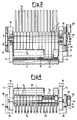
- Figure 3 shows a partially sectional top view of a portion of the device of the preceding figures;
- Figure 4 shows a partially sectional front elevation view of the device of Figure 3.
- Referring to the above cited figures, a feeding device according to the instant invention, applied to an
opener 1, comprises, in a per se known way, afeeding bin 2 from which amaterial 3 in form of fibre flocks or staple fibres is fed, at the basis of which two motor-driven feeding rolls 4 are provided in order to feed thematerial 3 from thebin 2 to aguide 5 situated above a feeding table 6. - The table 6 is constituted, in a known way, by
arms 7a of a plurality of swinginglevers 7 positioned side-by-side to each other, and hinged about asame shaft 8 perpendicular to the development of thelevers 7. Thelevers 7 are independent from one another and each of them has, besides thearm 7a directed towards the peripheral surface of a suitably lined preparing oropener roll 9, anopposite arm 7b, only partially visible in the drawings, capable of cooperating in a known way with a respective microswitch in case the angle of swinging of thelever 7 exceeds a preset value owing to the effect of coarse impurities in the material fed to theopener roll 9. A spring, not shown in the figures, tends to keep therespective lever 7 in a position close to afeeder roll 10 installed above thearm 7a of thelevers 7. - When the device operates, between the
feeder roll 10 and the levers 7 a gap remains, which allows the material in fibre form, fed by the revolutionary movement of thefeeder roll 10, to flow. The material then enters anair gap 11 defined between thefree ends 7c of thearms 7a of thelevers 7 and theopener roll 9, by undergoing a nipping action in a per se known way, which causes the opening of the fibres and the removal of the therein contained impurities. That action can be integrated byblades 12, also of known type, arranged in a known way. The directions of revolution of therolls - According to the present invention, for the purpose of optimizing the effect of opening and cleaning of the material and of supplying, at the outlet from the
opener 1, a high-quality prepared material destined to be submitted to the subsequent processing steps, the present invention provides for varying the position of the feeding table 6 relatively to theopener roll 9 as a function of the length of the fed fibres and of the degree of impurity of the material. - For that purpose, while the material in
fibre form 3 is being fed, the level of impurity of the same material is detected, preferably in continuous or at short time intervals, and on the basis of the detected data the position of the feeding table 6 (formed by thearms 7a of the levers 7) is varied -- preferably in continuous or at short time intervals -- relatively to theopener roll 9, so as to achieve the optimal treatment conditions. - In fact, the table 6 is supported with the possibility of shifting in a substantially radial direction relatively to the
opener roll 9, and positioning means for controlling the position of the table 6 are provided, which are controlled as a function of the data detected by animpurity detector 13 installed upstream the table 6, in particular at thefeeding bin 2. - More precisely, in the herein depicted example, the
shaft 8 on which theLevers 7 are hinged and thefeeder roll 10 are rotatably supported by twoside shoulders 14, so installed as to be capable of sliding in a substantial horizontal direction and radially relatively to theopener roll 9 between twofixed guides guides 16 has, externally to theshoulders 14, a portion provided with arack 17, with which arespective gearwheel 18 inmeshes. Eachgearwheel 18 is rigidly affixed to theshaft 8 which supports thelevers 7, so as to be able to rotate together with theshaft 8. At one end of the shaft 8 a worm-helical gearwheel transmission 19 is provided, which is capable of transmitting to the shaft 8 a revolutionary movement generated by aservomotor 20 supported, together with thetransmission 19, by abracket 21. - The
servomotor 20 is operatively connected with an electronic data processing andcontrol apparatus 22 operatively connected with detector means 13 which detect the impurities contained in thematerial 3, as well as further means disclosed in the following. The detector means 13 can be constituted by an optical detector, constituted by alight emitter 23 directed toward thebin 2 so as to take-in the whole width of thebin 2 and a portion of the height thereof, at which the opposite walls of thebin 2 are made transparent, and a light receiver screen 23a installed behind thebins 2. - The screen 23a, as a function of the amount of light which impinges on it -- and which is a function of the amount and of the quality of the impurities contained in the
material 3 -- sends corresponding signals to anelectronic unit 24 of theapparatus 22, which converts them into signals indicative of the level of impurity of thematerial 3 which at that time runs through thebin 2, in the region thereof monitored by the detector means 13. The signal generated by theelectronic unit 24 is sent to amicroprocessor unit 25 which, on the basis of the detected data and of the previously stored data, which supply the optimum distance between the table 6 and theroll 9 as a function of the level of impurity of thematerial 3 and of the length of the fibres, generates signals which control theservomotor 20 in order to cause this latter to adjust the position of the table 6 at the optimum distance from theopener roll 9. Anoperator station 26 makes it possible the data to be displayed, as well as the characteristic data of thematerial 3 to be stored in the memory of themicroprocessor unit 25. - One can realize that a certain delay will occur --depending on the distance of the impurity detection area from the area of nipping in the
air gap 11 and on the material feeding speed -- between the time at which the impurities are detected and the time at which the actuation of theservomotor 20 actually takes place. The revolutionary movement of this latter, by causing the associatedgearwheel 18 to rotate -- after a previous suitable speed reduction -- causes the whole table 6 with thefeeder roll 10 to shift along a rectilinear trajectory, with movements of approaching to, or of moving away from, theopener roll 9, according to the needs. In that way, the distance between theend 7c of the table 6 and theopener roll 9, i.e. thegap 11, is continuously controlled and, whenever necessary, changed, so as to change the intensity of nipping of the material, according to the quality and the amount of the impurities contained in the material, in order to accomplish optimal conditions of opening and cleaning of the material. The movement of the table 6, which movement occurs anyway over a limited stroke, does not have any effects on the contact between thearms 7b of thelevers 7 and the respective microswitches, a contact which is anyway sliding in a direction perpendicular to the direction of actuation of the microswitches by the same levers. - Furthermore, one might also think of controlling the position of the feeding table 6 in such a way that said position only undergoes an adjustment when from the comparison between the detected impurity data and the stored data a difference emerges, which is greater than a preset value.
- By means of a process and device according to the present invention, the characteristics of the material can be optimized in the step of preparation of said material for spinning, on considering both the length of the fibres, and the amount and the nature of the impurities. Inasmuch as neither the revolution speed of the
opener roll 9, nor the revolution speed of the feeding rolls 4 or of thefeeder roll 10 are changed, the material does not undergo any alterations in its dragging modality, but is only subject to a different nipping effect, more suitable for causing the fibres to be opened without being damaged, and with an improved cleaning effect. - Instead of the direct automatic control, a manual control of positioning of the table 6 could be provided as well, by manually adjusting the position of said table 6, on the basis of a purposely provided scale, as a function of the data displayed by the
electronic processing apparatus 22. - Of course, several other modifications are possible within the scope of the appended claims. So, e.g., the
servomotor 20 could drive to rotate a gearwheel inmeshing with a rack fastened onto a mobile structure supporting the table 6. The table 6 could also be of a type different from the table 6 formed bylevers 7, as herein illustrated and described, e.g., it could consist of one single element fastened to theshoulders 14. The detector means 13 could be constituted by a TV camera connected with theunit 24.
Claims (15)
- Process for feeding a material in fibre form, in particular in the form of staple fibres, in a machine, in particular an opener or a card, for preparing said material for subsequent spinning, in which process the material (3) is continuously fed to a feeding table (6) and is caused to flow between this latter and a preparing roll (9), and during the feeding of the material the level of impurity of the material (3) is detected, characterised in that on the basis of the detected data the position of the feeding table (6) relative to the preparing roll (9) is varied in a substantially radial direction in order to vary the air gap between said feeding table (6) and said preparing roll (9).
- Process according to claim 1, characterized in that the material (3) is submitted to an optical monitoring.
- Process according to claim 1 or 2, characterized in that the control for varying the position of the feeding table (6) is performed with a delay relatively to the detection of the impurity level, which delay depends on the distance between the area in which said detection is carried out and the area in which the material (3) is processed, and on the speed at which the material (3) is fed.
- Process according to one of the preceding claims, characterized in that the detection of the level of impurity and the adjustment of the position of the feeding table (6) are carried out continuously.
- Process according to one of claims from 1 to 3, characterized in that the detection of the impurity level and the adjustment of the position of the feeding table (6) are performed at short time intervals.
- Process according to one of the preceding claims, characterized in that the detected data is compared to the data scored in a memory and the control for adjusting the position of the feeding table (6) is only issued if from said comparison a difference greater than a preset value is evidenced.
- A device for feeding a material in fibre form, in particular in form of staple fibres, in a machine, in particular an opener or a card, for preparing said material for subsequent spinning, comprising a material feeding bin (2) through which the material (3) is continuously fed to a substantially horizontal feeding table (6) situated in the proximity of a rotary preparing roll (9) and defining an air gap (11) with said preparing roll (9), and further comprising at least one feeder roll (10) above the table (6) for conveying the material (3) towards the air gap (11) and a detector means (13) for detecting the impurity level of the material (3) upstream said feeding table (6), characterised in that the feeding table (6) is suported movable in a substantially radial direction relative to the preparing roll (9), in that means of positioning of the feeding table are provided and in that the gap (11) between the feeding table (6) and the preparing roll (9) is adjustable as a function of the data detected by said detector means (13) during feeding of the material (3).
- Device according to claim 7, characterized in that the feeding table (6) is supported by a mobile support structure operatively connected with a servomotor (20) controlled by an electronic data processing apparatus (22), which processes the data detected by said detector means (13).
- Device according to claim 7, in which the feeding table (6) is constituted by swinging levers (7) lying side-by-side to each other, independently hinged onto a same shaft (8), characterized in that the shaft (8) is supported by a structure movable in a substantially radial direction relatively to the preparing roll (9).
- Device according to claim 9, characterized in that said shaft (8) is rotatably supported by said structure and bears at least one rigidly affixed gearwheel (18) inmeshing with at least one rack (17) rigidly affixed to the fixed structure of the machine, said shaft (8) being driven to revolve as a function of the data detected by said detector means (13).
- Device according to one of claims 9 or 10, characterized in that it comprises two side shoulders (14) rotatably supporting said shaft (8) and a feeder roll (10), and that externally to said shoulders (14) two racks (17) are installed each of which is in engagement with a gearwheel (18) rigidly affixed to said shaft (8), with said shoulders (14) being slidable inside fixed guides (15, 16) provided on the machine.
- Device according to one of claims from 9 to 11, characterized in that said shaft (8) is operatively connected with a servomotor (20) actuated by an electronic data processing apparatus (22) which processes the data detected by said detector means (13).
- Device according to claim 7, characterized in that said detector means (13) comprise an optical detector arranged at said feeding bin (2).
- Device according to claim 13, characterized in that the optical detector is constituted by a light-emitter element (23) and a light-receiver element (23a) installed on opposite sides relatively to the feeding bin (2), adjacent to transparent walls of said bin (2).
- Device according to one of claims 8 or 12, characterized in that the electronic apparatus (22) comprises a microprocessor unit (25) storing data related to the parameters of impurity of the material (3) and to the parameters of position of the feeding table (6) and comparing the detected data with the stored data, as well as generating signals for controlling adjustment of the position of the feeding table (6), depending on the results of said comparison.
Applications Claiming Priority (2)
| Application Number | Priority Date | Filing Date | Title |
|---|---|---|---|
| IT02278089A IT1236911B (en) | 1989-12-21 | 1989-12-21 | PROCEDURE AND FEEDING DEVICE FOR FIBER MATERIAL IN A SPINNING PREPARATION MACHINE, IN PARTICULAR AN OPENER |
| IT2278089 | 1989-12-21 |
Publications (2)
| Publication Number | Publication Date |
|---|---|
| EP0436250A1 EP0436250A1 (en) | 1991-07-10 |
| EP0436250B1 true EP0436250B1 (en) | 1996-05-08 |
Family
ID=11200393
Family Applications (1)
| Application Number | Title | Priority Date | Filing Date |
|---|---|---|---|
| EP90203361A Expired - Lifetime EP0436250B1 (en) | 1989-12-21 | 1990-12-15 | Process and device for feeding a material in fibre form in a machine for preparing said material for the subsequent spinning, in particular an opener |
Country Status (5)
| Country | Link |
|---|---|
| US (1) | US5173995A (en) |
| EP (1) | EP0436250B1 (en) |
| JP (1) | JP2622194B2 (en) |
| DE (1) | DE69026919T2 (en) |
| IT (1) | IT1236911B (en) |
Families Citing this family (12)
| Publication number | Priority date | Publication date | Assignee | Title |
|---|---|---|---|---|
| DE4441254A1 (en) * | 1994-11-19 | 1996-05-23 | Truetzschler Gmbh & Co Kg | Device for opening and cleaning flake fiber material, for. B. cotton, synthetic fiber u. the like |
| GR960100084A (en) * | 1995-04-13 | 1996-12-31 | Trutzschler Gmbh & Co Kg | Apparatus on a carding machine |
| DE19516568A1 (en) * | 1995-05-05 | 1996-11-07 | Truetzschler Gmbh & Co Kg | Fibre flocking cleaning station |
| WO2009010995A1 (en) * | 2007-07-19 | 2009-01-22 | Marzoli S.P.A. | Device for the preparation of flock fibres to be supplied to a carder |
| CN106120033A (en) * | 2016-08-11 | 2016-11-16 | 成都市开悦化纤有限公司 | The classification of a kind of energy carries out opener and improves the opener method of product quality |
| CN106048785A (en) * | 2016-08-11 | 2016-10-26 | 成都市开悦化纤有限公司 | Cotton opener with hierarchical cotton opening function |
| CH713691A1 (en) * | 2017-04-13 | 2018-10-15 | Rieter Ag Maschf | Food trough and feeding device with a feed trough. |
| CH713690A1 (en) * | 2017-04-13 | 2018-10-15 | Rieter Ag Maschf | Food trough and feeding device. |
| CH713692A1 (en) * | 2017-04-13 | 2018-10-15 | Rieter Ag Maschf | Feeder. |
| CN108532038B (en) * | 2018-06-01 | 2023-05-12 | 嘉兴市华益股份有限公司 | Flax passes material and rolls up mechanism of unreeling |
| CH717715A1 (en) * | 2020-08-05 | 2022-02-15 | Rieter Ag Maschf | Fiber preparation machine with a camera. |
| CN118814321B (en) * | 2024-09-04 | 2026-05-01 | 河北嘉星绒业有限公司 | Cashmere carding machine |
Family Cites Families (16)
| Publication number | Priority date | Publication date | Assignee | Title |
|---|---|---|---|---|
| US2755512A (en) * | 1955-06-14 | 1956-07-24 | Ennis E Moss Jr | Bat type lint cleaner with resiliently mounted feed plate |
| US3562866A (en) * | 1968-10-23 | 1971-02-16 | Crompton & Knowles Corp | Density control for a textile lap former |
| GB1476319A (en) * | 1973-11-10 | 1977-06-10 | English Card Clothing | Fibre processing machines |
| US4100650A (en) * | 1974-04-17 | 1978-07-18 | Hergeth Kg Muschinenfabrik Und Apparatebann | Adjustable feed plate |
| DE2440224C3 (en) * | 1974-08-22 | 1978-11-09 | Fritz 7341 Bad Ueberkingen Stahlecker | Device for cleaning fiber material in an open-end spinning unit |
| DE2700972C3 (en) * | 1977-01-12 | 1980-06-12 | Truetzschler Gmbh & Co Kg, 4050 Moenchengladbach | Method and device for monitoring foreign bodies in a textile fiber fleece |
| CH623361A5 (en) * | 1977-07-18 | 1981-05-29 | Rieter Ag Maschf | |
| GB2067608A (en) * | 1980-01-18 | 1981-07-30 | Cosmopolitan Textile Co Ltd | Feeding fibres to carding machines |
| DE3205776C3 (en) * | 1982-02-18 | 1996-06-13 | Truetzschler Gmbh & Co Kg | Method and device for regulating the amount of fibers to be fed to a card |
| DE3534933A1 (en) * | 1985-10-01 | 1987-04-09 | Truetzschler & Co | DEVICE FOR MEASURING THE QUANTITY OF FIBERS TO BE SUPPLIED TO A TEXTILE MACHINE |
| DE3608514C2 (en) * | 1986-03-14 | 1997-12-18 | Truetzschler Gmbh & Co Kg | Device for homogenizing the sliver or nonwoven in a card, card or the like. |
| IT1228598B (en) * | 1986-09-25 | 1991-06-24 | Truetzschler & Co | DEVICE TO MAKE THE CARDA TAPE OR CARDA VEIL UNIFORM IN A CARDA |
| IN170276B (en) * | 1986-12-12 | 1992-03-07 | Rieter Ag Maschf | |
| IN170275B (en) * | 1986-12-12 | 1992-03-07 | Rieter Ag Maschf | |
| AT394453B (en) * | 1987-03-25 | 1992-04-10 | Oesterr Forsch Seibersdorf | METHOD AND DEVICE FOR DETECTING AND REMOVING FOREIGN MATERIALS FROM RAW COTTON |
| DE3734145A1 (en) * | 1987-10-09 | 1989-04-27 | Hollingsworth Gmbh | METHOD AND DEVICE FOR CLEANING AND OPENING FIBER FABRIC THAT IS IN FLAKE SHAPE, e.g. COTTON |
-
1989
- 1989-12-21 IT IT02278089A patent/IT1236911B/en active IP Right Grant
-
1990
- 1990-12-15 EP EP90203361A patent/EP0436250B1/en not_active Expired - Lifetime
- 1990-12-15 DE DE69026919T patent/DE69026919T2/en not_active Expired - Fee Related
- 1990-12-20 US US07/630,584 patent/US5173995A/en not_active Expired - Lifetime
- 1990-12-20 JP JP2411979A patent/JP2622194B2/en not_active Expired - Lifetime
Also Published As
| Publication number | Publication date |
|---|---|
| EP0436250A1 (en) | 1991-07-10 |
| DE69026919T2 (en) | 1996-09-19 |
| IT1236911B (en) | 1993-04-26 |
| IT8922780A0 (en) | 1989-12-21 |
| IT8922780A1 (en) | 1991-06-21 |
| DE69026919D1 (en) | 1996-06-13 |
| JP2622194B2 (en) | 1997-06-18 |
| US5173995A (en) | 1992-12-29 |
| JPH0450321A (en) | 1992-02-19 |
Similar Documents
| Publication | Publication Date | Title |
|---|---|---|
| US5173995A (en) | Process and device for feeding a material in fibre form in a machine for preparing said material for the subsequent spinning, in particular an opener | |
| US4457195A (en) | Automatic strip cutting machine | |
| EP0052412A1 (en) | Friction open-end spinning method and apparatus | |
| CN100453717C (en) | Apparatus having at least one separating knife in cotton carding machine, dust-colecting machnie or the like | |
| NO317278B1 (en) | Apparatus for cutting reinforcing fiber material | |
| US4188845A (en) | Strip cutter | |
| US4458381A (en) | Cotton ginning system embodying a lint cleaner | |
| US6865781B2 (en) | Method and apparatus at a spinning preparation machine for cleaning fiber material | |
| US3950920A (en) | Collecting system for batchwise collection of rod-shaped objects | |
| US4858278A (en) | Apparatus for cleaning and opening textile fiber material | |
| US4586218A (en) | Chute feed apparatus for a carding machine | |
| US4218414A (en) | Method for shredding and dry-defibrating compressed cellulose pulp and forming a batt of the resulting cellulosic fibrous material | |
| US3304584A (en) | Drafting mechanism | |
| GB2261646A (en) | Apparatus for feeding tobacco ribs to a cutting tool | |
| US4167378A (en) | Apparatus for shredding and dry-defibrating compressed cellulose pulp and forming a batt of the resulting cellulosic fibrous material | |
| US4224849A (en) | Device for detection of metal in a moved strand | |
| US3903570A (en) | Apparatus for forming a lap of textile fiber | |
| EP0072357A1 (en) | Rollermixer for rubber with completely automatically operating cycle | |
| JP2003193340A (en) | Device for setting initial draft adjustment value with sliver draft device such as drawing machine | |
| EP0212979B1 (en) | Method and apparatus for sequentially feeding sliver to drawing frame from fresh full can in continuous spinning system | |
| US4651758A (en) | Apparatus for detecting foreign objects in the distributor of a cigarette maker | |
| CN117958474B (en) | A tobacco destemming machine and its control method | |
| US5042343A (en) | Device and machine for cutting wire binding portions | |
| US4404711A (en) | Apparatus for withdrawing and gathering a fiber web | |
| GB2333768A (en) | Sheet handling apparatus with diverter |
Legal Events
| Date | Code | Title | Description |
|---|---|---|---|
| PUAI | Public reference made under article 153(3) epc to a published international application that has entered the european phase |
Free format text: ORIGINAL CODE: 0009012 |
|
| AK | Designated contracting states |
Kind code of ref document: A1 Designated state(s): CH DE FR GB IT LI |
|
| 17P | Request for examination filed |
Effective date: 19911206 |
|
| 17Q | First examination report despatched |
Effective date: 19931201 |
|
| GRAH | Despatch of communication of intention to grant a patent |
Free format text: ORIGINAL CODE: EPIDOS IGRA |
|
| GRAA | (expected) grant |
Free format text: ORIGINAL CODE: 0009210 |
|
| AK | Designated contracting states |
Kind code of ref document: B1 Designated state(s): CH DE FR GB IT LI |
|
| PG25 | Lapsed in a contracting state [announced via postgrant information from national office to epo] |
Ref country code: FR Effective date: 19960508 |
|
| ITF | It: translation for a ep patent filed | ||
| REF | Corresponds to: |
Ref document number: 69026919 Country of ref document: DE Date of ref document: 19960613 |
|
| EN | Fr: translation not filed | ||
| PLBE | No opposition filed within time limit |
Free format text: ORIGINAL CODE: 0009261 |
|
| STAA | Information on the status of an ep patent application or granted ep patent |
Free format text: STATUS: NO OPPOSITION FILED WITHIN TIME LIMIT |
|
| 26N | No opposition filed | ||
| REG | Reference to a national code |
Ref country code: GB Ref legal event code: IF02 |
|
| PGFP | Annual fee paid to national office [announced via postgrant information from national office to epo] |
Ref country code: GB Payment date: 20041215 Year of fee payment: 15 |
|
| PG25 | Lapsed in a contracting state [announced via postgrant information from national office to epo] |
Ref country code: GB Free format text: LAPSE BECAUSE OF NON-PAYMENT OF DUE FEES Effective date: 20051215 |
|
| GBPC | Gb: european patent ceased through non-payment of renewal fee |
Effective date: 20051215 |
|
| PGFP | Annual fee paid to national office [announced via postgrant information from national office to epo] |
Ref country code: DE Payment date: 20061207 Year of fee payment: 17 |
|
| PGFP | Annual fee paid to national office [announced via postgrant information from national office to epo] |
Ref country code: CH Payment date: 20061213 Year of fee payment: 17 |
|
| PGFP | Annual fee paid to national office [announced via postgrant information from national office to epo] |
Ref country code: IT Payment date: 20061231 Year of fee payment: 17 |
|
| REG | Reference to a national code |
Ref country code: CH Ref legal event code: PL |
|
| PG25 | Lapsed in a contracting state [announced via postgrant information from national office to epo] |
Ref country code: LI Free format text: LAPSE BECAUSE OF NON-PAYMENT OF DUE FEES Effective date: 20071231 Ref country code: DE Free format text: LAPSE BECAUSE OF NON-PAYMENT OF DUE FEES Effective date: 20080701 Ref country code: CH Free format text: LAPSE BECAUSE OF NON-PAYMENT OF DUE FEES Effective date: 20071231 |
|
| PG25 | Lapsed in a contracting state [announced via postgrant information from national office to epo] |
Ref country code: IT Free format text: LAPSE BECAUSE OF NON-PAYMENT OF DUE FEES Effective date: 20071215 |